
Chapter 10. Dynamics in Motion
3D animation can be fun and rewarding, especially when you get into the cooler effects that can really bring a scene to life. In the previous chapter, you were introduced to LightWave 10’s particles. This chapter will take you even further by showing how to create various dynamic effects for creative animations. These dynamic effects let you make animations in which objects collide realistically and influence each other’s motion in a way that obeys natural laws such as gravity, momentum, and shock absorption. Tools like these will help take your animations to the next level. You will work through various projects so that you can quickly and easily learn how to apply these powerful tools to just about any animation. In this chapter, you’ll learn about the following:
• Dynamics-related panels and tools
• Hard-body dynamics, governing solid, rigid objects
• Soft-body dynamics, governing objects that are yielding but resilient
• How to make objects collide and react
Dynamics in LightWave
The word dynamic is an adjective that relates to energy or to objects in motion. What puts these objects in motion in LightWave are clever commands that you control. To use any of the dynamics in LightWave, you just need to think about what you want an object to do.
Let’s say you have created a fun character with a big, uh, animator’s belly. As your character walks, you want his girth to shake a bit. Although you could use bones with a weight map and apply bone dynamics, a simpler and more effective method is to apply a “soft” dynamic to the jelly belly. Or perhaps you’re an avid bowler (or aspire to be). Instead of wearing those silly shoes to go bowling, just create some 3D bowling balls and pins and use hard dynamics and collisions to send the pins flying—without having to manually keyframe the ball’s contact with each pin in its path or each struck pin’s contact with other pins around it, and so on. LightWave motion dynamics features let you place objects in your scene, tell them how to move and interact with other objects, and then turn them loose to interact with each other—without manually keyframing all of their collisions and encounters. Once you’ve learned all the necessary buttons and processes, LightWave dynamics can make your scenes come to life. Now, take a quick tour of the dynamics-related panels to familiarize yourself with them.
Understanding Dynamic Controls
Dynamics in LightWave are easy to set up after you understand how the panels work and what the controls mean. Figure 10.1 shows the SoftFX dynamics panel. This panel is accessed through the Dynamics tab within the Object Properties panel, just as particle effect controls were in the previous chapter. You can see from the image that there are six tabbed areas within the dynamic controls.
Figure 10.1. When a dynamic is applied, the controls are found within the Object Properties panel.
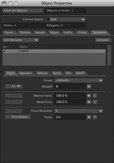
The number of tabbed areas varies depending on which dynamic you apply. As the tutorials progress in this chapter, you’ll see how the different areas are used.
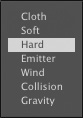
The types of dynamics you can apply to objects are as follows:
• Cloth
• Soft
• Hard
• Emitter (for particles)
• Wind
• Collision
• Gravity
Each of these dynamic types has a similar set of commands and controls. When you apply a dynamic to an object, you need to think about your process, just as you do when modeling or animating. Think about where you are going with the animation and what you want to do with it. Once you understand that, you can choose the appropriate dynamic for your object and know what tabbed area to access within the controls.
Hard-Body Dynamics
Hard-body dynamics have been around for a while, but few ordinary mortals have been able to take advantage of them. Complex scripting requirements and heavy calculations often made this top-notch feature available only to a few. Now, thanks to some clever programmers at NewTek, this feature is available interactively in LightWave 10.
Hard-body dynamics applies to objects that behave as rigid solids. When hard bodies collide, they retain their shapes without compressing or yielding. Think of marbles, billiard balls, or anvils. Hard-body dynamics control how these objects behave when they run into each other, based on properties such as gravity, weight, and density.
Exercise 10.1. Creating Hard-Body Dynamics
This tutorial will take a few basic objects and show you how to make them interact. From there, you’ll change variables to see the how the dynamic toolsets work.
- Open LightWave Layout.
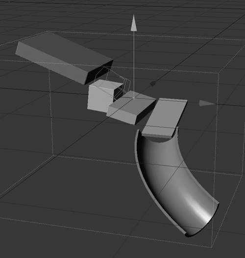
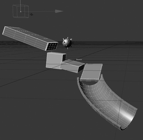
- Load the Solids model from the Chapter 10 folder of this book’s DVD (Figure 10.2 on the next page). This model has just one layer, containing a few geometric shapes set up as an “obstacle course.” Also, load the Ball model from the DVD’s Chapter 10 folder. You’ll use dynamics to animate the Ball object as it rolls around, and interacts with, the Solids model’s shapes.
Figure 10.2. The Solids model loaded, ready for some dynamic action. Exciting, isn’t it?
Note
If either the light or camera icon gets in the way of working, simply move it out of view. This project is a lesson in dynamics, and you won’t be lighting or rendering.
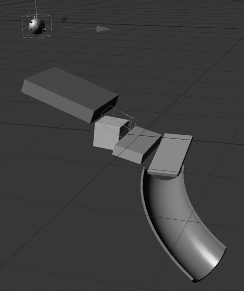
- Select the ball and move it up on the Y-axis so that it’s positioned above the top of the highest box. Create a keyframe at 0 to lock it in place, as in Figure 10.3.
Figure 10.3. Position the ball at the top of the slide.
- With the ball selected, press p to open the Object Properties panel. Although this tutorial is simple, you’ll see how cool the dynamic effects can be.
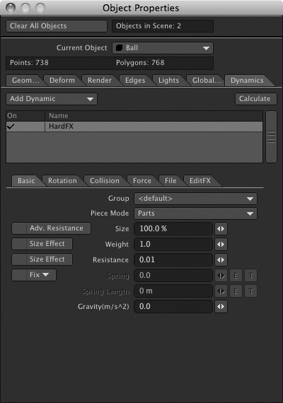
- Click the panel’s Dynamics tab, and select Hard from the Add Dynamic drop-down to apply a HardFX dynamic to the Ball object (Figure 10.4). Position your view so you can see the slide, ball, and Properties panel. Select the HardFX listing to see its controls.
Figure 10.4. Add a hard dynamic to the ball.
- Now that you’ve come this far, it’s a good idea to save the scene. Save this scene as SolidsSetup and then save it again as SolidsWorking, or something similar. The idea behind this is that at any point, you can call up the setup scene and start again.
Note
Don’t forget that you can also press Shift+S to save incremental versions of your scenes.
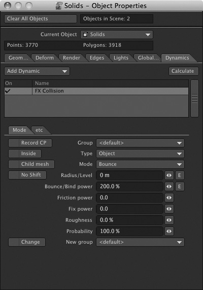
- In the Object Properties panel, choose the Solids object and add a collision dynamic to it from the drop-down list, as in Figure 10.5.
Figure 10.5. Use the Object Properties panel to add a collision dynamic to the slide object.
- If you click the Calculate button on the Dynamics tab, nothing happens. You’ve not yet given the dynamics any properties. So, go back to the Ball object and select the HardFX listing to access its controls. You need to click it only once for the controls to appear on the Dynamics tab.
- The first thing you want to do is give the ball some gravity. In the Basic tab of the HardFX controls, set Gravity to –9.8. It’s the last setting in the drop-down, and it corresponds to the acceleration due to gravity on Earth, 9.8 meters/second2. (The negative value reflects the fact that gravity pulls downward, along the negative Y-axis.)
- Set the last frame of the animation to 400.
- Click the Calculate button on the Object Properties panel’s Dynamics tab. Whoa! The ball falls and bounces down the solid object (Figure 10.6)!
Figure 10.6. With two dynamics applied, your animation starts to have interaction.
Believe it or not, that’s all there is to it! You’ve just created hard-body dynamics. However, there are many more controls to play with, so save the scene and move on to experiment a little.
You might have noticed that the ball doesn’t quite fall down through all of the obstacles. A few more adjustments are in order.
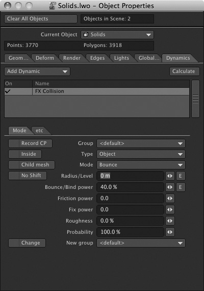
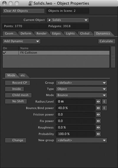
- Back in the Object Properties panel, select the FX Collision listing for the Solids object. Then, set the Bounce/Bind Power to 40% (Figure 10.7). The default 200% is way too “bouncy,” which is why this ball fell, and then bounced off into the air.
Figure 10.7. Reduce the Ball object’s Bounce/Bind Power setting to 40% from the default 200% to stop it from careening out of the scene.
- Click the Calculate button again, and the ball now slides down the objects better. But it’s still not quite right, is it?
- Select the Ball object in the Object Properties panel, and then select the HardFX listing.
- Increase the value of the Weight setting to 0.2. This will make the ball heavier. If you calculate again, the ball slides much better. But it slides. It should roll, shouldn’t it? You can change this too.
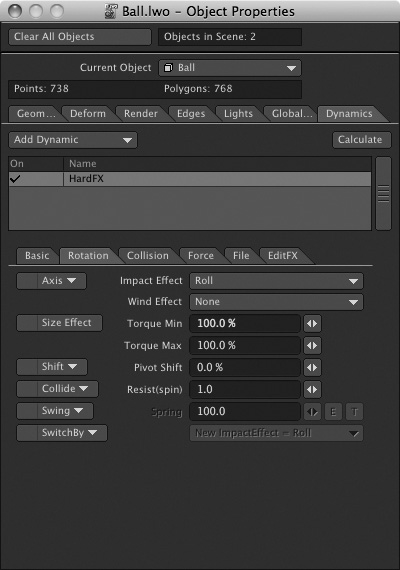
- On the Rotation tab, change the Impact Effect from Force to Roll (Figure 10.8).
Figure 10.8. Adding weight to the ball and changing the Impact Effect to Roll will change how the ball behaves.
- Click the Collision tab and change the Collision By option from Node to Sphere (Figure 10.9).
Figure 10.9. Adjusting the Collision By option lets your ball roll down the obstacles.
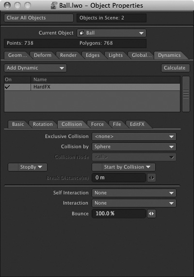
The Node setting tells LightWave to use every point within the object to calculate collision dynamics. That can be significant for complex models and interactions, but in a simple scene like this, containing simple geometric objects, the Node setting simply slows down your animation with excess calculation. Once you’ve set the Collision By option to Sphere, click the Calculate button.
- Once the calculation is finished, click the Play button at the bottom of the interface and you’ll see the ball roll smoothly down the solid objects.
- Click the Rotation tab, and to the left of the Impact Effect setting, you can tell the ball to roll on a specific axis only. Click the Axis drop-down list. It’s set to Free, but you can change this to the Y-axis (which might apply to a spinning top), the X-axis (for a wheel or yo-yo), and other variations. The Free setting is best for a rolling ball, so you don’t need to change anything here, but it’s a good idea to familiarize yourself with this important control.
- You can also change some of the other values, such as Wind Effect and Torque. If you increase the Torque Max value to 300%, for example, the ball will roll faster than it is currently moving. A good example of this is a children’s ball thrown into water, which has a lot of torque coming out of the child’s hand. It spins faster than it is moving (or sliding) on the water. Another example is a bowling ball thrown down an alley. Additionally, you can give the ball a Resist (Spin) setting to have it hold back on its spin amount.
Adjusting Other Collision Effects Controls
With just a few changes to these settings, you can make objects interact with each other. However, you might have noticed that there are more controls for collision effects than you’ve used here. Figure 10.10 shows these controls, which appear on the Dynamics tab of the Object Properties panel.
Figure 10.10. The collision controls are located mainly on the Mode tab, part of the Dynamics tab of the Object Properties panel.
The following list provides a rundown of its controls and settings:
• Setting a group through the Group drop-down is useful for times when you’re working with larger scenes and multiple objects. For instance, let’s say you have three slides going in this scene. You could create a group so that the collision and hard-dynamic objects are tied together and don’t react to other objects with dynamics applied. It’s a way of separating and isolating dynamics, while maintaining control.
• The Type drop-down specifies the surface shape that the selected object “shows” to objects that collide with it, and that is used to calculate the results of that collision, such as the angle at which a given object will ricochet away from its surface. The Object setting uses all the points on an object’s surface to calculate collision results; it provides the most realistic dynamics but requires a lot of processing power and rendering time. The Sphere, Box, and Plane settings calculate collisions as if the selected object, no matter how complex in shape, were one of those simpler objects. These options result in collisions that are not as precise, but they suffice in many instances, often appear no different, and can save a lot of rendering time. The Object-Subdiv setting lets you apply different collision properties to surface subpatches within a single object.
• The Mode drop-down determines how objects will react to the selected object when they collide with it. The default Bounce setting causes objects that strike the selected object to, well, bounce off it. Other options include Stick, Erase, Event, Scatter, and Attract. Stick and Attract have the effects you’d expect on colliding objects. Erase causes objects that strike the selected object to disappear from the scene. The Event setting causes the selected object to act as if it has been struck by another object when noncollision dynamic events occur, such as the activation of a wind effector. The Scatter option causes colliding objects to bounce off the selected object in a random fashion.
• The Radius/Level setting can change the collision position. For example, if you change this value from 0 m to 400 mm and then click the Calculate button again, the ball won’t fall and drop down the slide like it did before. Instead, it will “collide” with the slide before it actually touches it, because you’ve made the ball’s collision radius larger than its actual physical radius. Keep this setting at 0 for this project.
• The Bounce/Bind Power selector controls the strength of the collision behavior specified in the Mode drop-down: how bouncy a Bounce Mode setting is, how sticky a Stick setting is, and so on. Use the mini-slider or type in a percentage value to adjust these settings.
• The Friction Power control, also adjusted via the mini-slider or by typing a number into its requester, determines the amount of resistance the selected object’s surface exerts on other objects as they roll or drag across it. Increasing Friction Power for the slide to 20.0 rather than 0, for instance, causes the ball to move down the slide at a slower rate because of the extra friction. You can play with this value to see how the dynamics react, but for this project keep the setting at 0.
Note
When setting Radius/Level or Bounce/Bind Power, you can click the E buttons to the right of the values to change these settings over time. Make your ball bounce hard, and then suddenly stick.
• You can increase the Fix Power and Roughness to change how the collision reacts throughout the animation. Let’s say you increase Fix Power to 20. The ball will not bounce as much on the collision. It will not slow down, but rather stay attached to the collision object more throughout the calculation. Roughness, on the other hand, will make the ball bounce around, sort of like rough terrain. Set the value to, for example, 40%, and you’ll see the ball bounce down the slide. Change these values to add variations to see how the ball movement changes as it moves down the slide.
• Finally, you can set the Probability, telling LightWave the percentage of probability that the collision should happen. Right now, it’s set to 100%, meaning there’s a 100% probability of a collision. Lower this value, calculate again, and see the difference.
Within the HardFX controls, which are located on the Dynamics tab found in the Object Properties panel, click the Collision tab and then click the Start By Collision drop-down selector. Choose Collision in the Start By drop-down, and the ball’s dynamic effects will remain turned off until the ball collides with another object. Triggering the effect using this collision-detection method saves processing time. You can set a Stop By collision event in the same way. Simply click the Stop By drop-down selector and choose Stop By Event. The event would be the collision. In the previous exercise, turning on the Start By Collision option would yield a ball that just sits in the air, that doesn’t fall, and that doesn’t roll. If something were to hit it, like a 3D hand or baseball bat, this collision would start the effects.
As you can see, setting up hard-body dynamics is not too complicated if you slow down and think about the process. Think about what you’re going for, and it’ll come together. In the previous exercise, you had a ball, which you told LightWave was a “hard” object. If you calculated after applying this setting, you might have seen an error. That’s because LightWave doesn’t have anything to work with, and you need to set something for this object to interact with. So, you told the ball to collide with the Solids object. The Solids object had a “collision” applied.
So how about going a step further? The next exercise will show you how to shatter glass in 3D.
Exercise 10.2. Modeling for Dynamics
This exercise will show you how you can blow apart a window. The technique can be used for anything, from a creature crashing through a brick wall to a bowling ball knocking down a set of pins. The project you’ll do here will show you a quick technique for creating a window in Modeler, and then show you how to use dynamics in Layout to crash an object through it, essentially shattering the window—another hard-body dynamic effect.
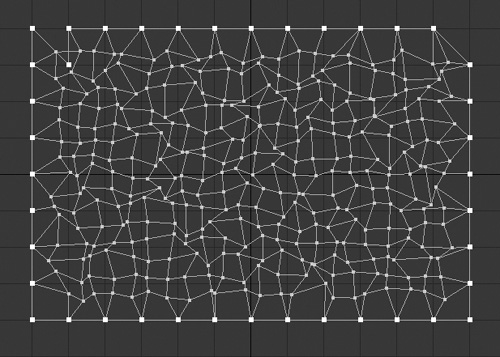
- Open Modeler and select the Box tool from the Create tab. Create a box in the bottom left (Back) view, about 10 m by 5 m, with multiple segments. You can do this by pressing n to open the Numeric panel and then setting the number of segments. Create about 24 segments or so for the X and 10 for the Y. This doesn’t have to be exactly like it is here; just make sure your box has many segments so that it can be broken apart. Figure 10.11 (on the next page) shows the model.
Figure 10.11. Create a box in Modeler that has multiple segments along its X and Y axes.
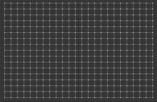
- If you’ve created your flat box and can’t see it in the Perspective view, press f to flip its polygons.
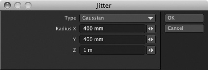
- Press Shift+J to activate the Jitter tool (also found on the Modify tab).
- In the Jitter panel that appears (Figure 10.12), enter 400 mm for both the X and Y values. Leave the Z-axis setting at 1 m.
Figure 10.12. Use the Jitter tool to shake up the shape of the polygons.
- Switch to Points selection mode at the bottom of the interface.
- Now, carefully select the very bottom-left point of the box, and holding the Shift key, select the point immediately above it, as shown in Figure 10.13.
Figure 10.13. Select, in order, the bottom-left corner point and the point just above it.
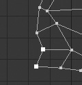
You’re selecting two points sequentially to tell Modeler which way you want your selection to go, for the next step.
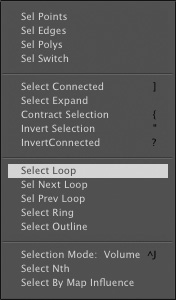
- So, from the Select drop-down at the top left of the interface, choose Select Loop, as shown in Figure 10.14.
Figure 10.14. Choose Select Loop to automatically continue the selection of points.
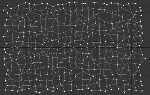
- Once you choose Select Loop, LightWave Modeler continues selecting points for you around the entire box, as shown in Figure 10.15.
Figure 10.15. Using Select Loop is an easy way to select the points around the entire box.
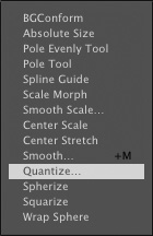
- With the entire outer edge of points selected, click the Modify tab, and at the bottom left under the Transform category, click the More drop-down button and then choose Quantize, as shown in Figure 10.16.
Figure 10.16. Select Quantize on the Modify tab.
- In the Quantize dialog box, leave all axis settings at 500 mm, as shown in Figure 10.17. You can simply enter .5 and press the Tab key to get a 500 mm setting.
Figure 10.17. Set the Quantize value to 500 mm.

- Click OK to apply the Quantize values, and as you can see from Figure 10.18, the selected points even out, except for a few.
Figure 10.18. Using the Quantize tool, you can even out the selected points.
- Press Control+T to activate the Drag tool, and then drag the few points that are sticking out of the perimeter back into line with the other points.
- Save your model as GlassWindow or something similar. You’re not quite finished.
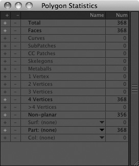
- Switch to Polygons selection mode, and then press w to open the Statistics panel (Figure 10.19). Look to the 4 Vertices listing. Click the plus (+) sign to its left, and all the polygons with more than four vertices will become highlighted.
Figure 10.19. Use the Statistics panel to select polygons with more than four vertices.
Note
There’s another way you could have created this model to this point. After you created the segmented box, you could have selected all of the polygons of the model except for those that make up the outer edge, and then applied the Jitter tool. Only those selected polygons would have Jitter applied, leaving the outer edge nice and even. The reason this exercise showed you another method was simply to have you work with a few more of Modeler’s tools. So, now you know. The choice is yours for future projects.
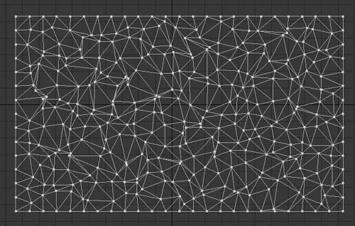
- Taking a look at your selection, it pretty much seems that all the polygons have more than four vertices. That’s fine, and while you’re not going to subpatch these polys, go ahead and press Shift+T to triple them—which is LightWave-speak for converting a selected group of polygons into triangles. These triangles will become “shards” of glass in the shattered-window animation.
- After you’ve tripled the polygons, click the Align button on the Detail tab. You might get a message saying that 20 polygons have been flipped. The Align tool looks at all the polygons, sees that the majority of them are facing in one direction, and flips the few other polygons that are facing the other direction (Figure 10.20).
Figure 10.20. Triple the polygons to break them up more, and use the Align tool to make them all face the same direction.
- We have one last thing to do, and this is probably the most important step. On the Detail tab, select Unweld. The reason this step is important is because in order to have another object break apart this glass window, the multiple polygons you just created can’t be attached to each other. Figure 10.21 shows the tool.
Figure 10.21. Use the Unweld command to disconnect all the polygons.

The adjacent polygons of your model share common points and side segments; in LightWave lingo, these polygons are welded together. The Unweld command converts each selected polygon into a discrete, self-contained object with sides and vertices all its own. Applying the Unweld command to the window surface will allow the dynamics engine to shatter the window by animating each triangular segment as an independent “shard.” If you did not unweld the points, the dynamics engine could only move or push the entire window object, even though it consisted of multiple segments.
Note
Even though unwelding separates each segment, the window is still one solid object. And, without using dynamics to break up the object, moving the object in Layout will still move the entire object, not the segments.
- After you’ve unwelded the points, save the object. That’s it! Your window is created.
If you want, select various polygons and apply different surface names to them. Select a few polygons, for example, press q, and then give those panes of glass a specific name and color. Deselect, then select some other panes, surface, color, and so on. The GlassWindow file in the Chapter 10 folder of this book’s DVD has this already done for you.
Exercise 10.3. Shattering Glass
This next exercise will shatter the glass window object built in the previous exercise. It’s similar to the earlier hard-body exercise, but with a few differences in settings.
- Load the GlassWindow_Setup scene from this book’s DVD. This is a glass window, much like the one created in Exercise 10.2, with its surface polygons unwelded. The main difference between this model and the window created in the previous exercise is that it contains a white-to-blue background, which won’t appear until you render your scene.
The dynamic collisions that will shatter the window object in this exercise require the window object’s polygons to be unwelded—converted to discrete, self-contained polygons that share no points or segments. Recall that we used the Unweld command in Exercise 10.2 to separate the window’s surface polygons into “shards” that can be animated independently.
- Set the scene’s final frame number to 200, using the number field at the bottom right of the timeline, and then select Collision from the Dynamic Obj drop-down on Layout’s Item tab (Figure 10.22 on the next page).
Figure 10.22. Add a dynamic object straight into Layout from the Items tab.
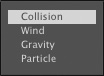
How is this different from the collision you added in Exercise 10.1? In that exercise, you added an object (named Solids) and told LightWave to make it a collision object. In this exercise, you’re creating a collision effector, which we’ll use to blow apart the GlassWindow object. Instead of building another object, you can just apply a dynamic effect directly. You can then even add a HyperVoxel explosion of particles to the effector to enhance the effect.
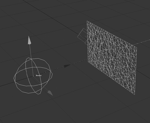
- When you add the collision effector, a panel will appear, inviting you to name the collision. This will be the only collision in the scene, so just click OK to keep the default name, Bounce. (This name is applied because the default collision mode option is Bounce.) The FX_Collision panel will appear, and you’ll see a wireframe sphere appear in the scene, representing the collision effector (Figure 10.23).
Figure 10.23. A dynamic collision effector in Layout, as represented by a wireframe ball.
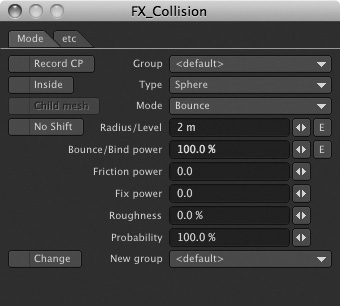
Take a look at the FX_Collision control panel, and you’ll notice the same controls that appeared on the Object Properties panel’s Dynamics tab throughout Exercise 10.1. LightWave often provides multiple locations for its controls.
- In the FX_Collision panel, increase the Radius/Level value to 2 m, as in Figure 10.24.
Figure 10.24. Increase the collision dynamic from the FX_Collision control panel.
- Click the Layout window and press t to activate the Move tool. Drag the collision object along the negative Z-axis until its entire volume is behind the GlassWindow object, and then create a keyframe at frame 0 to lock it in place.
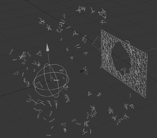
- Move the frame slider to frame 60, and then reposition the collision object along the positive Z-axis, until it is entirely in front of the GlassWindow object, and create a keyframe to lock it in place. Figure 10.25 shows frame 60 and the motion path the collision object follows between frames 0 and 60.
Figure 10.25. A small animation is created with the collision dynamic.
- Keep the collision object selected and press p to open the Object Properties panel. Click the Calculate button on its Dynamics tab.
Nothing will happen because you do not have anything to calculate. For the GlassWindow object to break apart, you must apply a hard dynamic to it.
- Click the GlassWindow object to select it (if it isn’t selected already), and then select Hard from the Add Dynamic drop-down on the Object Properties panel’s Dynamics tab (Figure 10.26).
Figure 10.26. Add a hard dynamic to the collision effector.
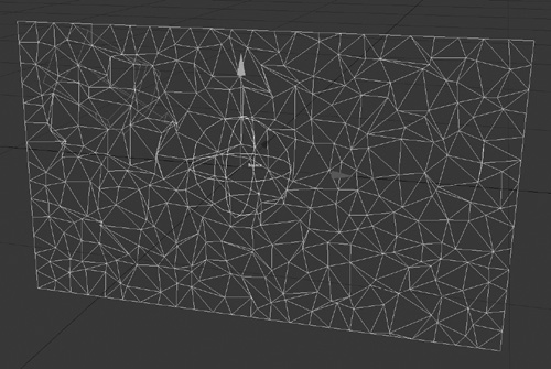
- Select the HardFX listing to access the controls, and you’ll see that Parts is selected in the Piece Mode drop-down. Change this to 1Piece and click the Calculate button. The collision dynamic in Layout hits the object and pushes the entire object away. This control is important to how your object breaks apart.
- Change the Piece Mode setting back to Parts and click Calculate. Ahh! There it is; the object breaks apart as the collision dynamic hits it (Figure 10.27).
Figure 10.27. Setting the Piece Mode to Parts allows the pane of glass to be shattered.
- You’re probably noticing that the pieces of GlassWindow break apart, but sort of drift off and do not really have any weight or motion of their own. In the HardFX controls for GlassWindow, choose –9.8 from the Gravity drop-down. Click Calculate, and you’ll see the object start to fall before and after the collision. That’s better, but you don’t want LightWave to apply the gravity until the collision happens.
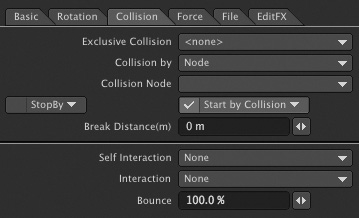
- Click the Collision tab of the HardFX controls and check Start By Collision, as shown in Figure 10.28. Then click Calculate again. GlassWindow sits still until the collision effector strikes it, and then its pieces expand and begin to drop.
Figure 10.28. Check the collision effector’s Start By Collision box to make the GlassWindow object sit still until it breaks apart.
From this point on, it’s a matter of tweaking the settings and observing the results until the animation looks the way you want it to look. None of the remaining steps in this exercise are essential or strictly “correct.” Try them all to acquaint yourself with the effects of the controls they describe, and decide for yourself if you want to keep the suggested settings, apply higher or lower values, or discard the adjustments altogether.
Note
If you want to make sure the exploding pieces do not collide with one another, you can choose Box from the Self Interaction drop-down on the Collision tab of the Object Properties panel’s Dynamics tab. Be careful, though, because this will greatly increase calculation times. You can always cancel a calculation by pressing the Control key.
- Click the Basic tab of the HardFX controls and increase the Weight setting to 35.0. This increases the weight of the pieces when they break up, resulting in heavier parts, which have more inertia and hit the ground faster. If you were animating something like paper, this weight value would be less, about 5 or 10.
- Click into Layout and select the dynamic collision object. Use the Dope Track to cut the keyframe at frame 60 and paste it at frame 20, and then click Calculate again. This increases the collision effector’s rate of acceleration as it collides with GlassWindow, and just like in the real world, that increases the force of the impact. By the same token, pasting the keyframe at, say, frame 120 will reduce the rate of acceleration and lower the force of impact.
- Set the Impact Effect to Roll in the HardFX panel’s Rotation tab (Figure 10.29). This will make the shards of glass spin as they spread away from the collision. Try playing with the Min and Max torque values to add more variety.
Figure 10.29. Set the Impact Effect to Roll to make the shards spin as they shatter and fall.

- Add one more thing to this animation and then get ready to learn about soft-body dynamics. Choose Collision from the Dynamic Obj drop-down on the Items tab to add another collision object to the scene, and type Ground when prompted to give it a name.
- When the FX_Collision panel opens for the Ground object, choose Plane from the Type drop-down. This makes a flat collision plane.
- Change the Radius/Level value for the Ground object to –7 m. This tells the collision to happen beneath the GlassWindow object, at –7 m on the Y-axis. Click the Calculate button and you’ll see the exploding parts now fall and hit a ground surface (granted, there is no visible surface).
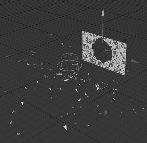
- The shards bounce a little too much when they hit the ground, don’t you think? So, reduce the Bounce/Bind Power value to 80% in the FX_Collision panel for the ground plane. Click Calculate again, and you’ll see the pieces fall and bounce randomly, as in Figure 10.30 (on the next page).
Figure 10.30. A Plane-type collision object makes the parts fall and bounce on the ground.
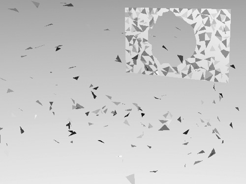
- Finally, you can use the Camera view to set up a cool moving camera as the glass breaks and flies toward you. Figure 10.31 shows a render with VPR. Save your scene!
Figure 10.31. Once the collisions and motions are set up, you can position your camera to have the shards of glass fly toward you.
You can use the techniques from the preceding examples to set up just about any collision in which rigid objects crash together and break apart or scatter. Here are a few more tips you can try when working with hard-body dynamics:
• On the Rotation tab in the HardFX panel, change Wind Effect to Roll. When your parts are exploded after the collision, they’ll roll, as if blown by the force of a shockwave in the air, radiating from the impact point. This adds a nice touch to exploding objects.
• On the Rotation tab of the HardFX panel, change the Torque Min and Torque Max values to balance the amount of initial and ending spin and motion on the exploding parts.
• Try changing the Pivot Shift value so that the exploding pieces rotate differently. At 0%, each part rotates around its own center point. Change this value to 100%, and the parts rotate as a group around a much larger radius, as if you’d moved all of their pivot points individually. You can also set this to just an X Shift, Y Shift, or Z Shift from the drop-down control to the left of the value requester.
• Increase the Resistance setting on the HardFX panel’s Basic tab, to slow down the exploding parts.
• If your exploding parts hop like little bugs after they land, try lowering the Ground object’s Bounce/Bind Power setting.
• Use the EditFX panel (as you did in Chapter 9, “Particle Animation”) to select and remove or reposition any individual shards as they scatter from the collision.
• Experiment with one setting at a time. Have fun!
What about soft things, like blankets or pillows? How do soft-body dynamics differ from cloth dynamics? When should you use one over the other? Read on to learn about more cool features of the dynamics in LightWave 10.
Soft-Body Dynamics
What is a soft-body dynamic? Is it just for making plump characters move naturally? That’s one thing it can do. But soft-body dynamics can do much more. A soft-body dynamic applies to any object that is... well, soft! More specifically, it’s anything that is soft and resilient; its surface yields when something hits it, but it reverts to its original shape after the collision. Think of a water balloon, a sofa cushion, or perhaps even the pants on a walking character.
Exercise 10.4. Working with Soft-Body Dynamics
- In LightWave Layout, save any work you’ve done and clear the scene.
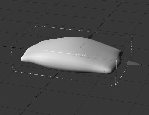
- Load the Pillow object from the Chapter 10 folder of this book’s DVD. Set up the view to a comfortable Perspective view and open the Object Properties panel for the object. Figure 10.32 shows the scene.
Figure 10.32. Load the Pillow object into Layout and view the scene from a Perspective view.
- On the Dynamics tab in the Object Properties panel, add a soft dynamic from the drop-down list for the Pillow object.
- Click the Layout window, and choose Collision from the Dynamic Obj drop-down on the Items tab. When prompted, type Ground to name the new object, which will provide a ground collision.
- For this collision dynamic, set Type to Plane and set Radius/Level to 0 m.
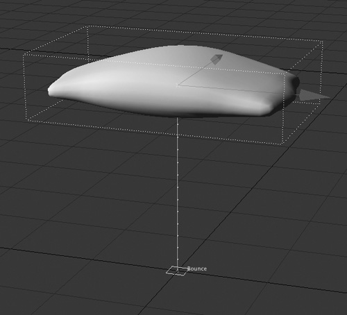
- Select the Pillow object and create a keyframe for its current position at frame 15.
- Use the Move tool (press t) to raise the Pillow object up about 20 m along the Y-axis (Figure 10.33). Create a keyframe at frame 0 to lock it in place.
Figure 10.33. Two keyframes are set for the Pillow object.
- Click the Calculate button in the Dynamics tab and watch the pillow fall. It bounces sort of like gelatin when it strikes the collision object.
Not very effective for a pillow...
- Click the Deform tab within the SoftFX controls. Make sure Collision Detect is set to All. Exclusive Collision should be set to None. Increase the Collision Size value to about 6 m, as in Figure 10.34.
Figure 10.34. Changing the values on the Deform tab tells the pillow how to react to the collision.
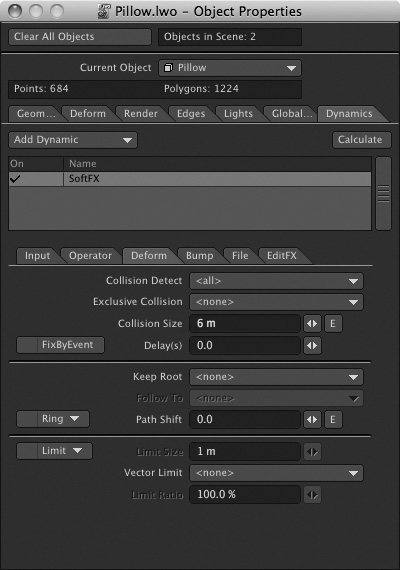
- Click the Calculate button. The pillow drops and looks better. It still bounces a bit too much, though.
- On the Operator tab for the pillow’s SoftFX, set the WaveCycle option for the Operator1 Map to 2.0. Then, set the WaveSize value to 0.2, as shown in Figure 10.35. Click Calculate again and your pillow looks more natural dropping into the scene.
Figure 10.35. Changing the pillow’s WaveSize and WaveCycle settings balances the amount the pillow bounces when it hits the ground.
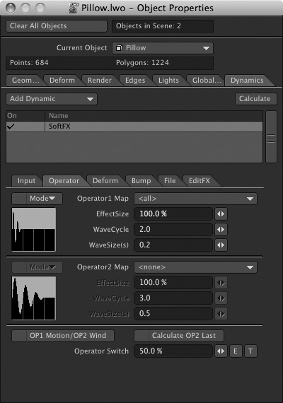
Changing the WaveSize value for the pillow tells LightWave how to calculate the motions after the dynamic is applied. You can even see a small thumbnail window of the wave’s motion, starting off more intense on the left and fading off over time to the right.
As you can see from this exercise, setting up objects with soft-body dynamics is easy. What other things can you think of to create with soft-body dynamics? Aside from things like tires hitting the ground or animating gelatin, soft-body dynamics can also be used for characters. You can define a point set in Modeler by selecting a group of points and then clicking New for Selection Set (the S button) at the bottom right of the Modeler interface. Then in Layout, use that selection set and the deformer for soft-body dynamics to make a character’s body parts jiggle. Fun stuff!
The Next Step
This chapter introduced you to hard- and soft-body dynamics. Even though the tutorials were simple, their methods and results are the same whether you’re building New York City in 3D or just a ball and box.
I can’t emphasize this enough: Practice! Experiment! Change a value; see the results. Work with one value at a time, and as always, consult your LightWave 3D manual for any specific technical questions. Now, turn the page and learn about LightWave 10’s bones tools for deforming objects.