
Chapter 8. Modeling Everyday Things
In its early years, few people would have described digital 3D as art (least of all most of its creators). Modelers and animators did some design work, of course, but they were mainly technicians. The time and money required to create 3D models, and the highly specialized (and limited) tools available to do the job, limited 3D’s uses to diagramming, engineering, and occasional Hollywood special effects. Today it’s different. Computing power, software advancements, and the ever-growing world of 3D content make truly artistic 3D model creation possible, and open the doors for you to go beyond your job as a 3D expert to create 3D scenes simply for the joy of creating. This chapter explores some of LightWave’s potential as an artistic tool.
Modeling Fruit
When you take a drawing or painting class, one of your first subjects is typically a still life—a grouping of objects that usually includes fruit or flowers, plus other items that contrast with them in texture, such as bowls or glassware. This chapter will take you on a journey in creating a still-life scene, but you’ll model and surface the objects, instead of painting or drawing them. Along the way, you’ll become even more familiar with the tools in LightWave 10.
Here are some of the key areas discussed in this chapter:
• Using LightWave Modeler tools
• Building everyday objects
• Positioning objects in Modeler
• Working with points, edges, and polygons
• Using more advanced modeling tools
• Building a still-life set
Clearly, the number one thing you need to complete any 3D project is patience. You might see some people’s work online and wonder just how they create those 3D images. Here’s how they do it: They work at it! There is no magic “make art” button in 3D (not even in LightWave). But by knowing the tools, and understanding your goal, you too can create anything you want. This chapter will help you do just that by breaking down the elements and stepping you through them, one piece at a time. If you’re ready, get a snack and a drink and start creating.
Begin with Bananas
Talk to anyone who has taken an art class and they will most likely tell you that there’s always fruit. Not to eat, but to re-create, through drawing or painting. That’s what this chapter is going to have you do, but digitally and in 3D. You’ll start with the leader of the fruit pack, the banana.
Exercise 8.1. One Banana, Two Banana, Three Banana, Four
If a catchy little tune popped into your head when you read this project’s title, you’re definitely showing your age. Yes, we’re talking about Fleegle, Bingo, Drooper, and Snorky—the Banana Splits gang from the ’70s television show. What does this have to do with modeling a 3D banana? Nothing! But it was a great way to get the exercise going. Now, on to the project:
- Open LightWave Modeler. This project begins by modeling the fruit that will be placed in your soon-to-be-modeled fruit bowl. You’ll start with a banana. Click the Create tab and select the Box tool.
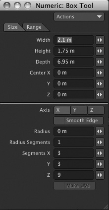
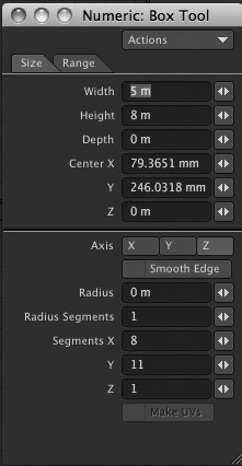
- Press n to open the Numeric panel, select the Size tab if it’s not already selected, and create a box by entering the values shown in Figure 8.1.
Figure 8.1. Create a box with multiple segments to begin creating a banana.
- Once you’ve entered the settings, close the Numeric panel or move it aside, and then press the spacebar to quickly turn off the Box tool. Remember, you can turn off tools by pressing the spacebar. Choosing another tool automatically turns off the current tool.
- Save your work.
- Press the spacebar again, until the Edges selection-mode button is highlighted at the bottom of the interface.
- In the Back view, at the bottom left, using your right mouse button (the Control key and mouse on the Mac), lasso-select the upper-right corner of the box. This will select the edge running along the top corner, down the Z-axis, as shown in Figure 8.2.
Figure 8.2. Lasso-select the top right edge of the box.
- Now select the three other edges. To do this, hold the Shift key to add the selection, and then right-click around each corner from the Back view. Figure 8.3 shows the four selected edges.
Figure 8.3. Select the remaining three edges. Now, all four edges of the box should be selected.
- Now you’ll bevel the selected edges. You can’t use the usual bevel command when it comes to edges. For this, you’ll use the EdgeBevel tool. On the Multiply tab, select EdgeBevel under the Extend category. You can also just press Control+B. As soon as you do, you’ll see the edges expand, as in Figure 8.4.
Figure 8.4. As soon as you activate EdgeBevel, your model begins to change.
- Notice that with EdgeBevel active, yellow highlights appear around the edges. This is normal; it also means that the tool is active. Click and drag in one of the views and you’ll see the amount of the bevel change. You can select the Numeric button at the bottom of the interface to see the specific values. Set the EdgeBevel to 300 mm, as in Figure 8.5.
Figure 8.5. Set the EdgeBevel to 300 mm.
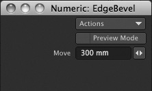
Note
The requester for EdgeBevel shows an option to enable Preview Mode. Doing so allows you to preview the EdgeBevel, which is shown with blue outlines in the viewports. The bevel is not actually applied but only previewed.
- Close the Numeric panel and turn off EdgeBevel. You’ll notice that the edges are still selected. That’s good, because you can tell Modeler to convert this selection from edges to polygons. From the Select drop-down menu at the top left of the interface, choose Sel Switch, which switches your selection from edges to polygons, as shown in Figure 8.6.
Figure 8.6. You can use Sel Switch to convert from one selection to another.
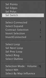
Note
How does Modeler know to switch the current selection to polygons? Good question! If you had Edges selected, the next option is Polygons. If you had Polygons selected, the next option is Points. If you had Points selected, the next option is Edges. Just as you press the spacebar multiple times to toggle between the three selection models, the Sel Switch tool works in a similar fashion.
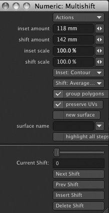
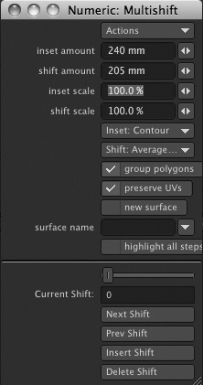
- With the newly created polygons now selected, click the Multishift tool on the Multiply tab under the Extend category. Then, open the Numeric panel from the bottom of the interface. Basically, you want to bevel these polygons running down the corners of the soon-to-be banana. But LightWave’s Bevel tool will separate the multiple polygons. Instead, Multishift can be used to bevel groups of polygons.
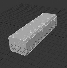
- In the requester for Multishift, make sure Group Polygons is checked on. Then, click and drag in a viewport to bevel the selected polygons. Moving the mouse left and right will change the Inset amount, while moving the mouse up and down changes the Shift amount. Set the values to 118 mm for the Inset, and 142 mm for the Shift. Figure 8.7 shows the values.
Figure 8.7. Using Multishift, you can bevel large groups of selected polygons.
- Turn off the Multishift tool and close the Numeric panel.
- Save your work. Feel free to save incrementally by pressing Shift+S.
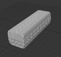
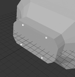
- In the Back view, select the center row of polygons for each side of the elongated box. You might find that some of the end polygons become selected as well, and that’s normal. After you select the desired polygons, hold the Control key and click the polygons you want to deselect. Figure 8.8 shows the selection.
Figure 8.8. Select the center row of polygons for each side of the box.
- At the bottom of the Modeler interface is the Modes menu. Click this and choose Action Center: Selection. This tells Modeler to apply tools based on the selection, not on the mouse position, as it was by default.
- Then, press Shift+H to activate the Size tool. Click and drag in the Back view to expand the size of the selection about 15 percent. As you click and drag, pay attention to the lower-left corner of the interface. The Numeric panel will show your Size value as you use the tool. The default is 100%, so you’ll want to click and drag to size the selection to 115%. Figure 8.9 shows the result.
Figure 8.9. Increase the size of the selection by 15 percent.
- Turn off the Size tool by clicking it or pressing the spacebar. If you look at Figure 8.9, you might notice that the ends of the object are a bit gnarly. Let’s fix that. First, deselect the currently selected polygons by pressing the / key on your keyboard. You can also click into a blank portion of the menu in Modeler.
- Change to Points selection mode at the bottom of the interface to tell Modeler you want to work with points (also known in the 3D industry as vertices).
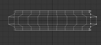
- In the Right view, using your right mouse button (Control-click on the Mac), lasso-select the endpoints of the box on the negative Z-axis. You should have 28 points selected, as shown in Figure 8.10.
Figure 8.10. Lasso-select the endpoints on the negative Z-axis.
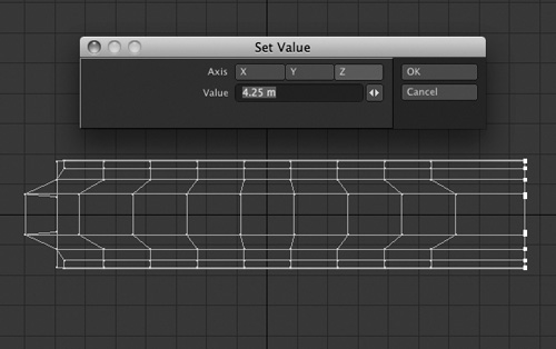
- Now, position your mouse just to the front of the selection, and take a look at the info area at the lower-left corner of the interface. As you move the mouse, you’ll see the numeric position. Note the Z-axis position at about 4.25 m. Then, press v to access the Set Value dialog box.
- Choose Z for the axis, and enter the value you noted from your mouse position, 4.25 m. Click OK and the selected points will jump to that value on that axis, as shown in Figure 8.11.
Figure 8.11. Using the Set Value dialog box, you can quickly adjust all points to one position.
- With the newly positioned points still selected, activate the Move tool (press t) and then move them back toward the model a bit, about 500 mm.
- Now you’ll bevel the polygons on this end. You adjusted the points using Set Value to flatten out the polygons. This will make your life easier when trying to bevel. But you want to bevel polygons, not points, so rather than deselecting points and reselecting polygons, use the Sel Switch command as you did earlier. From the Select drop-down menu at the top left of the interface, choose Sel Switch. The selected points now change to selected edges. Run the command again, and the selected edges become selected polygons.
- Press Shift+A to fit the selection to view.
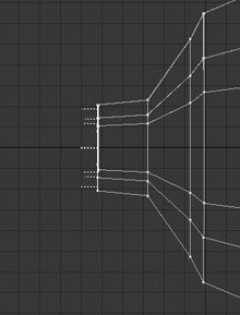
- When you bevel polygons, there are times when the geometry crosses over itself, creating unwanted results. So before you bevel, adjust a few points. Press Control+T to activate the Drag tool. Then, click and drag the points that make up the ends of the EdgeBevels you created earlier. Do this in the Back view.
It’s important to understand that first rule of modeling here—if nothing is selected, whatever you do applies to everything. So if you were to drag points in the Back view, the points would change all the way down the elongated box. But since just the polygons are selected from step 24, the point adjustment from the Drag tool in the Back view affects only the selection. The result is that you’re editing only the end of the object.
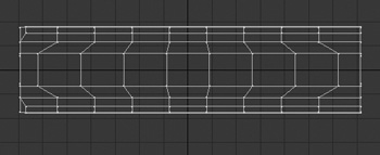
- Drag the points in to flatten out the EdgeBevels, as shown in Figure 8.12.
Figure 8.12. Using the Drag tool on selected polygons, you can click and drag the points of the EdgeBevels to flatten them out.
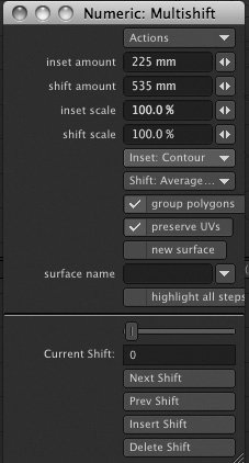
- Once you’ve adjusted the EdgeBevels, select the Multishift tool on the Multiply tab. Click and drag the selected polygons to 225 mm for the Inset and 535 mm for the Shift. You can use the Numeric panel as you did earlier for specific value entry. Figure 8.13 shows the change.
Figure 8.13. Using Multishift, bevel the end polygons to create one end of the banana.
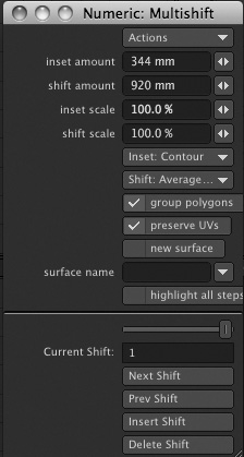
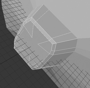
- Right-click one time to reset the Multishift tool, effectively adding to the existing geometry with a new bevel. Multishift the selection without allowing the corners to cross, about 344 mm for the Inset and 920 mm for the Shift. Figure 8.14 shows the operation.
Figure 8.14. Perform one more Multishift to multiply the selection, but be careful not to cross the corners.
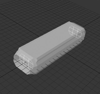
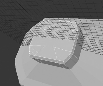
- Press Shift+H to select the Size tool. This will automatically turn off the Multishift tool. Reduce the selection size down to about 80%, as in Figure 8.15.
Figure 8.15. Now that you have additional geometry for the end of the object, you can scale it down. This will help avoid edges and points from crossing over each other as they would with the Multishift tool.
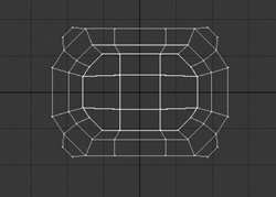
- Deselect the ends of the edge polygons, leaving just the nine polygons that make up the center, as shown in Figure 8.16. If it’s easier, deselect all polygons and then select just the center nine polygons.
Figure 8.16. Deselect the small edge polygons in the corners, leaving just nine polygons selected.
- You need to use Multishift again, but if you kept the edge polygons selected, you would start to see some serious errors. So with just the nine polygons selected at the end of the object, turn on Multishift and set the Inset to 240 mm with a 305 mm Shift. Figure 8.17 (on the next page) shows the result.
Figure 8.17. Using Multishift, extend the end polygons just a bit farther.
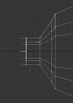
- Turn Multishift off, then turn it on again to extend the selection just one more time. But this time, apply a Shift value of only 240 mm (Figure 8.18).
Figure 8.18. Multishift the selection again, but only for a Shift value, not for an Inset value.

- Close the Numeric panel and turn off the Multishift tool. Then, deselect the polygons.
- Save your work!
- Select the four points that make up the very center of the newly created polygons, and size them down, as in Figure 8.19. This helps even out the mesh at the end, and will allow you to add additional Multishift operations if you want.
Figure 8.19. Scale down the center points on the end of the geometry.
You’re probably wondering at this point how it’s all coming together, so before you move on to add more details, how about taking a look at the overall progress?
- Make sure any points or polygons are deselected. Then, press a to fit all objects to view.
- Press the Tab key. What? You got an error? That’s OK—don’t worry. Click OK to close the error warning and press Tab again to turn off the attempted subpatch. Close the second error box.
You see, the beveling of edges earlier in the chapter changed the subpatch mesh so that some of its polygons have more than four sides. Earlier versions of LightWave balked at that, but LightWave 10 can handle larger polygons using Catmull-Clark subdivisions.
- From the bottom of the interface, you’ll see the SubD-Type drop-down menu. Change this to Catmull-Clark.
Catmull-Clark subdivisions are sometimes referred to as n-gons. Essentially, by using this method of subdivision, your objects do not need to conform to just three or four vertices like the old Subpatch method. The original Subpatch method still works well, and modeling with quads (polygons with four vertices) in mind is always the best way to approach a model. However, at times you need to go beyond convention, and this is where Catmull-Clark subdivisions come in handy.
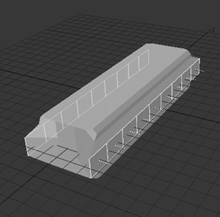
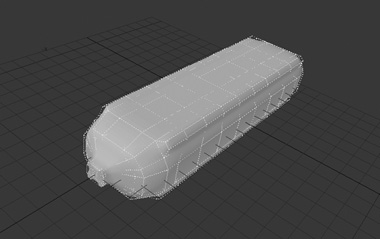
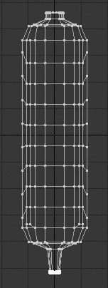
- With the SubD-Type set to Catmull-Clark, press the Tab key. Ah, no error message! Figure 8.20 shows the banana starting to take shape.
Figure 8.20. Using Catmull-Clark subdivisions, the original box is starting to look like a banana. Sort of.
- Make a few more detail changes and you’re almost there. First, press the Tab key to turn off the SubD mode. It’s sometimes better to work with subdivision mode disabled for speed and visual ease. It can be confusing to see the subdivision cage when trying to adjust edges.
- Make an incremental save by pressing Shift+S.
- Now, how about tightening up the shape of the end polygon? Make sure Polygons selection mode is set at the bottom of the interface, and Control-click the nine polygons that make up the end of the banana.
- Press Shift+] (the right bracket key) to expand the selection, as in Figure 8.21.
Figure 8.21. Select the end polygons of the banana.
- Press h to select the Stretch tool from the Modify tab.
- Stretch the selection to about 65% along the X-axis and 93% along the Y-axis, as in Figure 8.22.
Figure 8.22. Scale the end of the banana so that it’s more a square than a rectangle.
- Turn off the Stretch tool (or press the spacebar), and then deselect the polygons (press /).
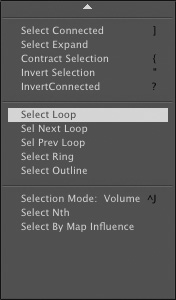
- In the Top view window, click any edge of the banana tip’s base. Then, from the Select drop-down menu at the top left of the interface, choose Select Loop. The entire edge loop will be selected (Figure 8.23).
Figure 8.23. The Select Loop option lets you quickly select an entire edge.
- With the edge selected, press Control+B to activate the EdgeBevel tool. Click and drag to bevel the selected edge about 20 mm or so (Figure 8.24).
Figure 8.24. Bevel the edge to add detail at the neck of the banana.
- Select the outer edge of the banana tip, and bevel it as well (Figure 8.25).
Figure 8.25. Bevel the outer edge of the banana tip.
- Using the right mouse button, lasso-select the points of the end of the banana and extend them about 180 mm on the negative Z-axis, as shown in Figure 8.26.
Figure 8.26. Select the points around the end of the banana and move them out on the negative Z-axis.
- With the points still selected, change the Action Center setting to Mouse (mentioned earlier in step 16), using the Modes drop-down list at the bottom of the interface. Then, press y to select the Rotate tool. Click and drag slightly in the Top view, directly on the edge of the selected points, to rotate the selection in a clockwise direction, about 15 degrees. By setting Action Center to Mouse, you’re telling Modeler to make adjustments based on your mouse position. Therefore, a Rotate command will pivot around where you click and drag. Figure 8.27 shows the rotation.
Figure 8.27. Rotate the endpoints about 15 degrees.
- At this point, you can use all of the tools and procedures we’ve already covered in this project to adjust the model as you like. Feel free to use the Drag tool to adjust the ends, bevel additional edges, and sort of “mess up” the model a bit so it’s not so perfect. On your own, repeat the Multishift, Drag, and Size operations on the other end of the banana. The only difference is that there wouldn’t be as much of a stem as there is on the end you’ve already been working on. Figure 8.28 shows one way in which bevels and other adjustments can be applied to the opposite end of the banana.
Figure 8.28. Use the Drag, Multishift, and Size tools to create the base of the banana on the opposite end of the model.

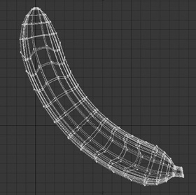
- OK, now all you need to do is bend it. On the Modify tab, select Bend. Then in the Back view, click in the center of the object and drag to the right. Bend the object as you like.
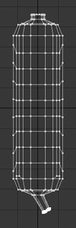
- One last thing to get you in a banana state of mind: Press q and apply a surface name of Banana to your model. Also, give it a bit of a yellow color. You can always change this later. Save your banana. Figure 8.29 shows the result.
Figure 8.29. Bend the banana as you like and add a surface to it.
At this point, you can adjust the model as you like. Perhaps the banana made here is too fat. No problem. Undo the bend, then using the Size tool in the Back view, adjust the banana. Then, bend again. You can also use the right mouse button to lasso-select any ring of points around the banana, and then size them to add imperfections in the shape, and so on.
This project showed you how a simple box can be made into an organic shape. LightWave’s edge tools, multiply tools, and basic modification tools allow you to easily create any shape you like. Add to that Catmull-Clark subdivisions and you can work without having to keep your model to three or four vertices.
This is just the first part of the still-life project, but also the longest. The next projects will have you model some additional fruit such as an orange and grapes. From there, you’ll build a bowl and a set for the objects.
Orange You Glad You Got This Book?
Wow, these project titles are lame, but it’s just so easy to make stupid jokes. Why should modeling fruit be so serious? This next project will show you how to model an orange. Sure, it’s just a ball, but there are a few small details you’ll add to help “sell” it.
Exercise 8.2. Model an Orange with the Multishift and Magnet Tools
- In Modeler, be sure your banana from the previous project is saved. Then, from the File drop-down menu at the top of the interface, select New Object.
- Creating an orange is easy, and most of its detail will come from surfacing. But there are a few things you’ll do now. First, on the Create tab, select the Ball command.
- Holding the Control key to constrain all axes, click and drag in the Top view to draw out a ball on the Y-axis. This should be about 3 m in size.
- Still holding the Control key, click and drag in either the Back or Right view. Alternatively, you can draw out at once in the Perspective view.
- Press the spacebar to commit to the new object. Figure 8.30 (on the next page) shows the model.
Figure 8.30. Create a ball with a radius of 3 m on every axis.
- Press F2 to center the object at the origin. Press a to bring the model to view.
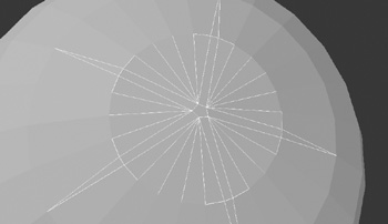
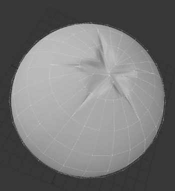
- Taking a look at the top of the ball, you can see how the geometry all comes together. It’s not that smooth and useful in many situations, but for an orange, these “poles” at the top of the ball can help create the detail. You want to select five areas of edges at the top of the ball. Starting from the center point, and making sure you’re in Edge selection mode, click to select the edges, as shown in Figure 8.31.
Figure 8.31. Select two edges from the center point at the top of the ball. Do this five times.

Note
When selecting the edges at the top of the ball, be careful not to select the edges at the bottom of the ball. This will happen if you use a Wireframe view to select. Instead, select the edges in a wireframe shaded view, such as the Perspective view. Pressing Shift+A to fit the selection to view will also help you see if you have more selected than you should.
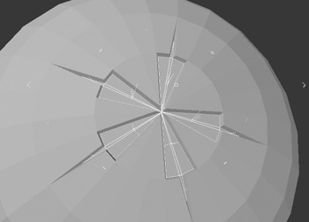
- The selected edges do not need to be even and, in fact, shouldn’t be. These edges will become the area where the stem will be. With the edges selected, press Control+B for EdgeBevel and bevel them about 20 mm, as shown in Figure 8.32.
Figure 8.32. Bevel the selected edges.
- Turn off EdgeBevel, and then choose Sel Switch from the Select drop-down menu. This changes the selected edges to selected polygons. Be sure to deselect any unwanted selections. You might have a few extra outside of the initial edge areas.
- Using the Multishift tool from the Multiply tab, click and drag to bevel the selected polygons just a bit. Bevel them about 5.8 mm for the Inset, and 4 mm for the Shift. Figure 8.33 shows the operation.
Figure 8.33. Bevel the selected polygons with the Multishift tool.

- Turn off the Multishift tool. The polygons will still be selected, and you’ll adjust them next.
- Save your orange!
- Click the Modify tab and select the Magnet tool. This will give you the effect of the Drag tool, but with a falloff.
- Right-click (Control-click on the Mac) in the Top view and drag. You’ll see a blue outline appear (Figure 8.34 on the next page). This determines the amount of influence the Magnet tool will have.
Figure 8.34. Using the right mouse button with the Magnet tool, you tell Modeler how much influence the tool has.
- Click and drag down on the selected polygons in the Back view. Remember, this is a drag tool with a falloff, so what you’ll see is the polygons being moved, but only within the circumference area you specified with the right mouse button. Figure 8.35 shows the operation.
Figure 8.35. Use the Magnet tool to bring just the center of the selected polygons down into the orange.
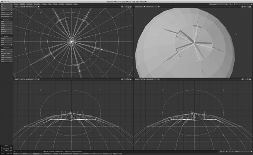
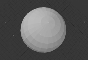
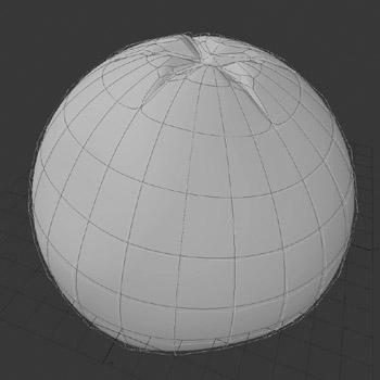
- Turn off the Magnet tool (press /) and then deselect the polygons. Save the object. Then, press the Tab key to turn on subdivision surface mode. You should still be using Catmull-Clark subdivisions (Figure 8.36).
Figure 8.36. With Catmull-Clark subdivisions applied, the bevels at the top of the orange start to shape up.
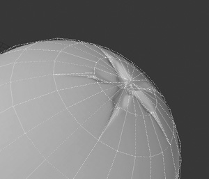
- Press Control+T to turn on the Drag tool. Now, take some time and click and drag the points around the top of the orange to smooth out the beveled areas. Just shape it, and clean it up so that the bevels are more separations in the skin rather than sharp cuts (Figure 8.37).
Figure 8.37. Use the Drag tool to adjust the shape of the orange.
- Save your model when you’re done tweaking. Then, note that the rest of the orange is simply too round. You need to shape it slightly. Use the Magnet tool again, but this time, set the range of influence (with the right mouse button) to encompass most of the orange. Then, with the left mouse, click to effectively push parts of the orange to shape it. Figure 8.38 shows the effect.
Figure 8.38. Use the Magnet tool to shape the orange, or basically deform it a bit, so it’s not so perfectly round.
- Press q to call up the Change Surface dialog box. Create a surface name of Orange for the object and give it a little color. Save your work.
Much of the orange’s surface will really come from texturing, which you’ll do later, so be sure to refer to Chapter 3, “Texture Creation.” But the initial shape is also important, as you’ve seen in this project. Now, let’s move on to using a few more modeling tools to create grapes.
Create a Cluster of Grapes
This next project will show you how to create a cluster of grapes in LightWave 10 Modeler. Later, you’ll call up this object and place it in a large bowl that you’ll model, along with the banana and orange.
Exercise 8.3. Bunches of Fun with the Clone and Magic Bevel Tools
- Save anything you’ve been working on, and from the File drop-down menu, select New Object.
You might have noticed that you’re not building with layers in these projects. You could if you wanted to—create the banana in one layer, the orange in another, and the grapes in a third layer. But instead, you’re building entirely new objects. This is good because these objects can be used to build your 3D library, as they are saved as individual objects. It also helps eliminate any confusion as to what you’re working on, and for this project, you’ll use multiple layers to help the modeling process. Having multiple objects in different layers might make your life difficult with the upcoming steps.
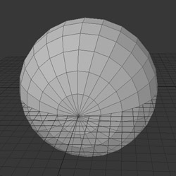
- On the Create tab, select the Ball tool. Create a ball the same size as you did in the previous project (when you created the orange). Press F2 to center the ball. Figure 8.39 shows the ball.
Figure 8.39. Begin creating grapes by making a simple ball.
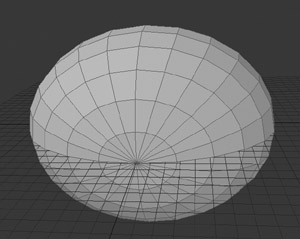
- Press h to activate the Stretch tool, and then click in the Back view and drag up slightly to elongate the ball. Figure 8.40 shows the result.
Figure 8.40. Use the Stretch tool to elongate the ball.
- Click a new layer at the top right of the interface. Place the ball as a background layer by clicking beneath the slash mark in the first layer.
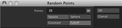
- On the Create tab, click the Random Points tool in the Points category. In the panel that appears, enter 35 in the Points field and then check on Sphere and Falloff, as shown in Figure 8.41.
Figure 8.41. Use the Random Points tool to create a clump of points.
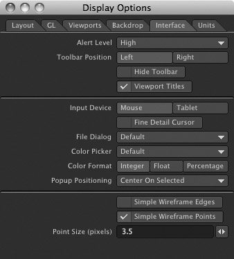
- You’ll see a group of points created in the views. The points might be hard to see, but there’s a way you can adjust that in Modeler. Press d to call up the Display Options panel. Click the Interface tab, and check Simple Wireframe Points. Set the Point Size to 3.5, as shown in Figure 8.42.
Figure 8.42. Increase the visual appearance of points in the Display Options panel.
- Click OK to close the Display Options panel. With these points now created, press ’ (the apostrophe key) to reverse layers. This puts Layer 1 in the foreground and Layer 2 in the background.
- On the Multiply tab, click the More drop-down menu in the Duplicate category. Select Point Clone Plus. A large panel appears (Figure 8.43).
Figure 8.43. Once the Point Clone Plus tool is set up, you’ll be able to duplicate your foreground object based on the point positions in the background layer.

- Enter a few settings:
For Random Rotation:
• Min H: 20
• Min B: 30
For Random Size:
• Min: 0.75
• Max: 1.0
- Leave all other settings at their defaults. Basically, the Point Clone Plus tool will generate duplicates of the foreground layer (the ball) based on the position of the points in the background layer. The values you’ve just set are simply adding some randomness to the duplicated objects. Click OK to close the Point Clone Plus tool and see what happens (Figure 8.44).
Figure 8.44. The Point Clone Plus tool creates 35 duplicates of the ball (grape), each with randomness throughout.
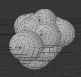
- Wow! Those are some fat grapes! Why did this happen? The size of the initial ball was too large based on the position of the points. Click Control+Z (Command+Z on the Mac) to undo the Point Clone Plus operation.
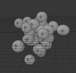
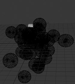
- Press Shift+H for the Size tool, and size down your grape about 30 percent. Then, rerun the Point Clone Plus tool. The settings you’ve entered will still be there. Click OK, and you’ll see a clump of grapes, as in Figure 8.45.
Figure 8.45. Using Point Clone Plus along with a ball has created a clump of grapes.
- A few grapes might be overlapping other grapes, and some might be floating too far out from the rest. You can easily move these with a few steps. Making sure you’re in Polygons selection mode, click once on a grape. Then press the right bracket key, the shortcut for the Select Connected command. Every polygon connected to that selection (the rest of the individual grape) is now selected. Press t and move the grape.
- Feel free to resize, rotate, and adjust the grapes as needed. You don’t need to be too precise because these grapes will end up in a bowl, but if you plan to use them later for something more close-up, try to align them more accurately so that none are overlapping. If you feel you need an additional grape or two, select one, press Control+C to copy, move the selected grape, and then press Control+V to paste.
- To deselect, press the / (forward slash) key.
- Continue adjusting the grape positions as you like, and remember to save your work.
- Press q to open the Change Surface dialog box. Create a surface named Grapes, and give it a bit of color. Perhaps you prefer red grapes over green seedless? Click OK to close the panel and save your object.
- To create a stem for added impact, go to a new layer, leaving the grapes in a background layer. This process can get tedious to make a branch extend from each grape. However, it’s easy to create the initial look, starting with a box.
- Create a small box just above the clump of grapes in the new layer, as shown in Figure 8.46.
Figure 8.46. To begin creating the stem for the grapes, build a small box above the grapes in a new layer.
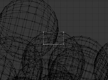
- Select just the bottom polygon of the box, as shown in Figure 8.47.
Figure 8.47. Select just the bottom single polygon of the box.
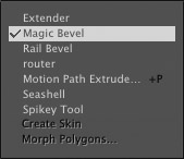
- Click the Multiply tab, then click the More drop-down menu in the Extend category and select Magic Bevel, as shown in Figure 8.48.
Figure 8.48. Choose the Magic Bevel tool from the Multiply tab’s Extend category.
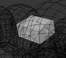
- When you turn on the Magic Bevel tool, you’ll see small circles appear around the box (Figure 8.49).
Figure 8.49. Magic Bevel begins with small circles on each polygon.
- Click and drag the circle at the bottom of the box, and drag downward into the grapes. You can do this in the Back or Right view. Feel free to move the mouse slightly to create a curvature. Figure 8.50 shows the result.
Figure 8.50. Click and drag the bottom circle to instantly create a multiple-beveled object.

- Press the spacebar to turn off the Magic Bevel tool. Then, click its button to turn it on again. You’ll now see circles for the Magic Bevel on each of the newly created polygons (Figure 8.51 on the next page).
Figure 8.51. Turning Magic Bevel off and then on again resets the tool so you can apply it to newly created geometry.
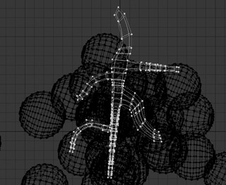
- In the Back view, click and drag downward from the middle of the stem, creating another branch, like the one shown in Figure 8.52.
Figure 8.52. Create another branch from the middle of the original stem.
- In the Right view, create another stem.
- From here, you can apply new Magic Bevels to the stems you’ve created. If you open the Numeric panel, you can adjust their scale. Changing the value to 100% prevents the bevel from tapering as it extends when you click and drag. You can also choose to spin the bevels as they are created.
- After you’ve created a few branches, press the spacebar to turn off the Magic Bevel tool. Then, press / to deselect.
- Make sure Subpatch is selected in the SubD-Type drop-down list at the bottom of the Modeler interface, and then press the Tab key. You’ll see the beveled box become smooth (Figure 8.53). Subpatch is the LightWave native subdivision surface setting and it likes polygons made up of three or four points. However, there are times when polygons within models are made for more than three or four points, and for those, you would choose the Catmull-Clark subdivision option.
Figure 8.53. Apply subdivision surfaces to the stem by pressing the Tab key.
- You can adjust points as you like, and even bevel a single polygon on the stem before you apply a Magic Bevel, to help determine the shape. When you’ve finished shaping the stem, assign it a surface using the Change Surface dialog box (press q).
Note
You can also apply subdivision surfaces to the grapes to smooth them out.
- Press Control+X (Command+X on the Mac) to cut the stem from the current layer. Switch to the grape layer, then press Control+V (Command+V on the Mac) to paste it. Save your object.
The stem is not attached to the grapes, but you can connect it up if you like. Use the Magic Bevel tool to drag a stem bevel right to each grape, or move the grapes around to touch the stem, but keep in mind that the stem is not going to be seen too closely in the final shot, since the grapes will be sitting in a bowl. And hey, speaking of bowls, let’s make one!
Building a Fruit Bowl
Building a fruit bowl doesn’t sound very exciting, does it? This next project, while not glamorous or too complex, is nevertheless important for your still-life scene. Furthermore, you can use the lathing technique it demonstrates to build plates, glasses, and other similar vessels.
Exercise 8.4. Sculpting with Splines and the Lathe Tool
- From the File menu in Modeler, select New Object.
- Press the comma key three times to zoom the Modeler view. This changes the overall grid to 2 m. You can see the grid size in the lower-left corner of the interface.
- On the Create tab, select the Spline Draw tool in the Curves tools category.
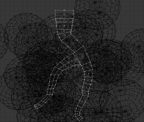
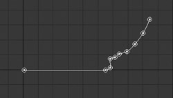
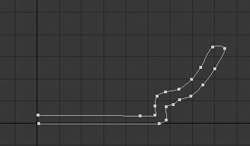
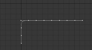
- In the Back viewport, click on the origin to create a point, and then click a few grids to the right along the X-axis, then again slightly above that, and so on, until you have an arc of nine or ten points that provides a cross-section of the bowl’s outer profile, from its center on the Y-axis to its outer rim on the right (Figure 8.54).
Figure 8.54. Using the Spline Draw tool, you can begin creating a curve to model a bowl.
- Click a little to the left of your last point to create a lip for your bowl, then click a new series of points, more or less parallel to the first set, to shape the bowl’s inner-surface profile, ending back at the Y-axis (Figure 8.55).
Figure 8.55. Continue creating points to finish building the cross-section of the bowl.
- Before you commit to this curve, you can click and drag any point you’ve created to adjust it. Be careful to precisely click on any point you want to adjust. Clicking near a point will add a new one and continue your curve.
Note
If you find that it’s difficult to create a point close to another point, just click a bit farther away, and then drag the point in closer to the desired position.
- When you’ve got the points along the curve positioned as you like, press the spacebar to turn off the Spline Draw tool.
- Switch to Points selection mode, and select the two endpoints on the Y-axis.
- Press v to open the Set Value dialog box. Choose X for the Axis, and set the value to 0 m. Click OK, and the selected points will be positioned exactly at the origin. This is important for the upcoming steps.
- Deselect the two points.
- From the Multiply tab, select the Lathe tool from the Extend category.
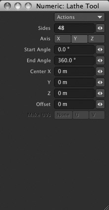
- Press n to open the Numeric panel, and you’ll quickly see the tool activate. The default axis for the lathe is the Y-axis, so that’s good! You’ll also see that End Angle is set to 360 degrees; that’s also good, because we want to apply the lathed shape through a full circular sweep. (If you’d wanted to make a “half-bowl” [or Hollywood Bowl] shape instead of a fruit bowl, you could have set End Angle to 180 degrees.) The only default setting you need to change is Sides, from 24 to about 48. This will help smooth out the object, as shown in Figure 8.56.
Figure 8.56. Changing the Sides value to 48 adds more detail to the lathed curve.
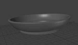
- Press the spacebar to turn off the Lathe tool. Use the Change Surfaces panel (press q) to give it the surface name Bowl (how original!), and then save the object. Figure 8.57 shows the final bowl.
Figure 8.57. The final fruit bowl, before it’s filled up with tasty treats.
- Save your bowl (press s).
Now that you’ve seen how the Lathe tool works, can you see why it was important to use the Set Value dialog box to set those two endpoints? We lathed around the Y-axis, and setting the X-values of the endpoints to 0 ensured that they’d lie on that axis, at the bowl’s exact center. Positive X-values for the endpoints would have created a hole in the bowl, and negative X-values would have caused the center of the bowl to overlap itself, complicating the model needlessly. Neither error would really be noticeable once fruit is placed in the bowl, but you should learn to build items like this the right way.
Perhaps you want to make a bottle or a glass? Use this exact process for a clean, smooth model. You can also use a Spline Curve with the Lathe tool to create very tight but smooth corners—sort of the same effect as beveling an edge, but with less work.
Now, let’s fill up the bowl.
Exercise 8.5. Filling a Fruit Bowl
You could use Modeler to arrange your still life by loading each piece of fruit and the bowl and pasting them each into separate object layers, but you’ll have more flexibility if you simply load each object into a scene in Layout and position them there.
- Open LightWave Layout and click the Items tab. From the Load category, select Object. When the Load Object dialog box appears, you can select all of the objects you created in this chapter: the banana, the orange, the grapes, and the bowl. Click OK to load them. Figure 8.58 shows the objects loaded from the Perspective view.
Figure 8.58. The four objects you created in this chapter are loaded into LightWave Layout.
- The objects aren’t quite in the bowl, are they? That’s OK—you can easily position them now. First, select the Orange object. Press Shift+H to size the object. Scale it up to about 1.8. You can click and drag to size it, and watch the values in the lower-left corner of the interface.
- Note that your Auto Key should be on and the timeline slider at frame 0. Once the orange is up to size, press t to select the Move tool. Move the orange up on the Y-axis until it rests on the bottom of the bowl. You can then move it off to one side of the bowl.
- With the orange still selected, press Control+C to activate the Clone tool. When the Clone dialog box appears, enter 5 to make five copies of the orange.
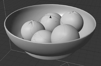
- You can use the up arrow on your keyboard to select each orange copy. Then, move each one to fill the bowl, as in Figure 8.59. Don’t be afraid to rotate them for a more random look, and place one on top of another.
Figure 8.59. Clone the orange and position the copies in the bowl using the Move and Rotate tools.
- Save your scene by pressing Shift+S. Name the scene FruitBowlSetup or something similar.
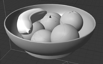
- Now take your banana and position it on top of the orange. Remember that when you select the Move and Rotate tools, you can use the handles to specifically control position on a desired axis. Figure 8.60 shows the banana in place.
Figure 8.60. The banana you modeled is positioned on top of the oranges.
Note
When using the Move tool, dragging with the right mouse button constrains movements to the Y-axis. With the Rotate tool, dragging with the right mouse button constrains to the Bank channel.
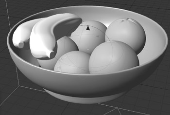
- Clone the banana by pressing Control+C one time and position the copy on top of the existing one, with a slight offset as in Figure 8.61.
Figure 8.61. A second banana suddenly becomes top banana.
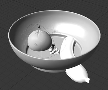
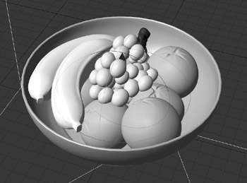
- Finally, select the grapes and position them with the other fruit, resting on the oranges and the side of the bowl. Feel free to resize, rotate, and reposition the grapes until you like the way they look. Figure 8.62 shows the bowl of fruit.
Figure 8.62. The bowl is now full of fruit in LightWave Layout.
- Save your scene and hop back into LightWave Modeler. You can press F12 to get there.
You can see that working in Layout to position, size, and clone the objects is a bit easier than doing so in Modeler. You can quickly clone, position, and rotate in real time. Perhaps more to the point, Layout is where you’ll render the final scene. Now there’s one more thing to do: Create a set for the fruit bowl.
Building a Set for the Still Life
When creating a still-life scene, you need more than just a bowl of fruit. You can’t just have a bowl of fruit floating in 3D space. Instead, you can use a cloth. Yes, LightWave can create cloth, and in this exercise, you’ll model it. In this project, you’re not animating the cloth, but it’ll be fun to model it.
Exercise 8.6. Modeling a Tablecloth
- In LightWave Modeler, create a new object.
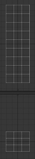
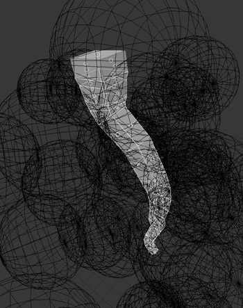
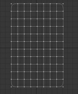
- Create a box in the Back viewport, specifying 5 m for the width and 8 m for the height. For the segments, enter 8 for the X, 11 for the Y, and 1 for the Z, as shown in Figure 8.63.
Figure 8.63. Create a tall, flat box with multiple segments to begin making your cloth.
- Turn off the Box tool. If you can’t see your object in the Perspective view, make sure the polygons are facing toward the negative Z-axis. You can press f to flip them.
- Press the Tab key to activate subdivision surfaces for the object.
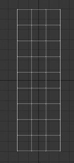
- Make sure you’re in Polygons selection mode, and using the right mouse button, lasso-select around the top two-thirds of the polygons, as shown in Figure 8.64.
Figure 8.64. Lasso-select the top two-thirds of the box.
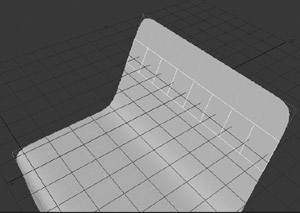
- On the Modify tab, select the Rotate tool. Make sure your Action Center is set to Mouse from the Modes drop-down menu at the bottom of the interface. Then, in the Right view, click and drag at the very bottom of the selection, and bend the selected polygons back on the Z-axis. Figure 8.65 shows the example.
Figure 8.65. Using the Rotate tool, the tall box is bent backward to create a smooth fold.
- The reason you’re rotating the selection rather than bending is that you want to create a tabletop look. The Rotate tool, in combination with the subdivisional surface, makes a tight, smooth edge. Now, turn off the Rotate tool, and then deselect the middle third set of polygons, so that only the top third remains selected.
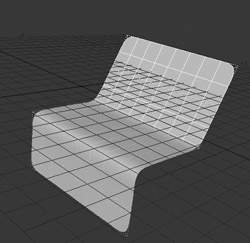
- Activate the Rotate tool again (press y) and then click on the base of the selection to rotate the selection upward. Don’t rotate a full 90 degrees; give it just a bit of a pitch (Figure 8.66).
Figure 8.66. Rotate the top third of the object upward to create the back of the tabletop set.
- Deselect the polygons, apply a surface name to the object using the Change Surfaces dialog box (press q), and then save it as ClothSet or something similar.
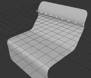
- Select the second row of polygons from the top, as shown in Figure 8.67.
Figure 8.67. Select the second row of polygons from the top of the set.
- On the Multiply tab, select QuickCut 1 from the More drop-down list under the Subdivide category. The selected polygon will be split in two, and the new points will automatically be selected.
- With the points selected, press t to activate the Move tool, and then move the selected points forward along the Z-axis just a bit, to create a bump in the cloth.
- Press y and, in the Back view window, rotate the selection slightly (Figure 8.68).
Figure 8.68. Move and rotate the split row of points to create a bump in the cloth.
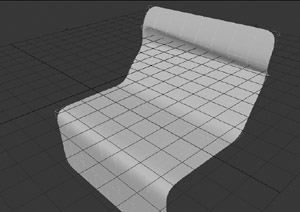
- Click the Polygons selection-mode button and Control-click each polygon in the row beneath the row of points you just adjusted to select the entire row.
- Run the QuickCut 1 command again, and move the newly created points back toward the first bump, creating another ripple (Figure 8.69).
Figure 8.69. After another QuickCut operation, move the second row of points to help fold the cloth a bit more.
- Save your model.
From here, you can continue bending, quick cutting, and adjusting points to create folds in the cloth. You can use the Drag tool (Control+T) to click and drag any points for added adjustments. What makes this work is that you’re adjusting the points of the model in a subdivision surface mode. That helps smooth out all the geometry, thus making a smooth cloth. When you’ve finished, save the object and send it to Layout. You can send it to Layout by using the command in the upper-right corner of the Modeler interface (click that small triangle to access the Send to Layout command). You can also just load it in Layout as you did with the fruit.
- In Layout, position the set underneath the bowl of fruit. If you need to size the set, make sure Auto Key is enabled so that your changes are captured.
- Be sure to check your cloth set position not only from the Perspective view, but from a Right or Left view as well. Figure 8.70 shows the setup from the Perspective view.
Figure 8.70. The modeled cloth is positioned and sized to fit under the bowl of fruit, in Layout.

- Save your scene.
There you have it! Still life! Well, it’s not complete yet. LightWave offers you control to model just about anything you want. There are many ways to build objects, and this chapter gave you a very good overview of the toolset and how it can be used to create smooth organic shapes. You can take the exercises here even further by modeling more fruit, such as a pear or an apple. How about taking the lesson of the bowl and creating a wine bottle to add to the scene?
The Next Step
What’s really going to make this shot stand out is the texturing, lighting, and rendering. You’ll be doing all of this soon, but before you move on to these key Layout features, stay in modeling mode and learn how to create more detailed objects in the next chapter.