
Chapter Three. Visualization and Sketching
Objectives
After studying the material in this chapter, you should be able to:
1. Define the terms vertex, edge, plane, surface, and solid.
2. Identify four types of surfaces.
3. Identify five regular solids.
4. Draw points, lines, angled lines, arcs, circles, and ellipses.
5. Apply techniques that aid in creating legible well-proportioned freehand sketches.
6. Apply techniques to draw irregular curves.
7. Create a single-view sketch.
8. Create an oblique sketch.
9. Create perspective sketches.
10. Create an isometric sketch of an object.
Refer to the following standard:
• ANSI/ASME Y14.3 Orthographic and Pictorial Views

Complex Surface Models Created Using 3D CAD (Courtesy of Professor Richard Palais, University of California, Irvine, and Luc Benard.)
Understanding Solid Objects
Sketches and drawings are used to communicate or record ideas about the shape of 3D objects. Before starting to sketch, it helps to develop a vocabulary for understanding and discussing 3D shapes.
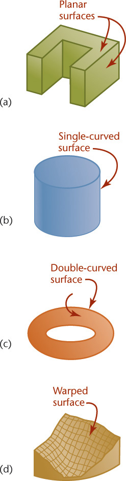
Three-dimensional figures are referred to as solids. Solids are bounded by the surfaces that contain them. These surfaces can be one of the following four types:
• Planar
• Warped
Regardless of how complex a solid may be, it is composed of combinations of these basic types of surfaces. Figure 3.1 shows examples of the four basic types of surfaces.
Types of Solids
Polyhedra
Solids that are bounded by plane surfaces are called polyhedra (Figures 3.2–3.4). These planar surfaces are also referred to as faces of the object. A polygon is a planar area that is enclosed by straight lines.
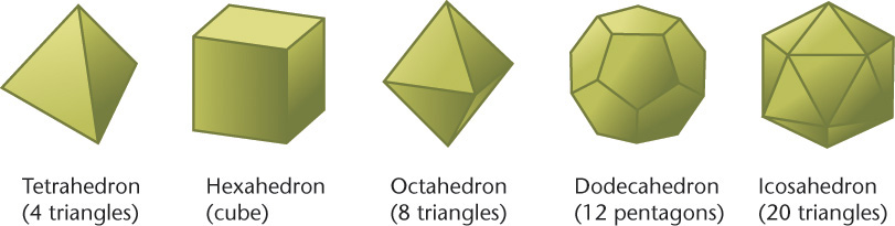
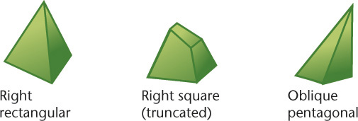
Regular Polyhedra
If the faces of a solid are equal regular polygons, it is called a regular polyhedron. There are five regular polyhedra: the tetrahedron, hexahedron, octahedron, dodecahedron, and icosahedron (Figure 3.2).
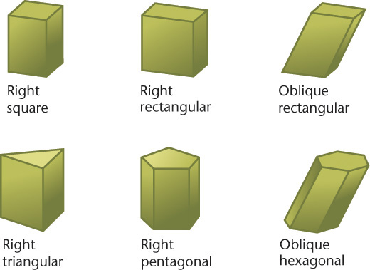
Prisms
A prism has two bases, which are parallel equal polygons, and three or more additional faces, which are parallelograms (Figure 3.3). A triangular prism has triangular bases, a rectangular prism has rectangular bases, and so on. (If a prism’s bases happen to be parallelograms, the prism is a called a parallelepiped, a word rarely heard in everyday conversation.)
A right prism has faces and lateral (side) edges that are perpendicular to the bases; an oblique prism has faces and lateral edges that are angled to the bases. If one end is cut off to form an end that is not parallel to the bases, the prism is said to be truncated (a word that simply means “shortened by having a part cut off”).
Pyramids
A pyramid has a polygon for a base and triangular lateral faces that intersect at a common point called the vertex (Figure 3.4). The line from the center of the base to the vertex is called the axis. If the axis is perpendicular to the base, the pyramid is called a right pyramid; otherwise, it is an oblique pyramid. A triangular pyramid has a triangular base, a square pyramid has a square base, and so on. If a portion near the vertex has been cut off, the pyramid is truncated, or it is referred to as a frustum.
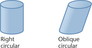
Cylinders
A cylinder has a single-curved exterior surface (Figure 3.5). You can think of a cylinder as being formed by taking a straight line and moving it in a circular path to enclose a volume. Each position of this imaginary straight line in its path around the axis is called an element of the cylinder.
Cones
A cone has a single-curved exterior surface (Figure 3.6). You can think of it as being formed by moving one end of a straight line around a circle while keeping the other end fixed at a point, the vertex of the cone. An element of the cone is any position of this imaginary straight line.

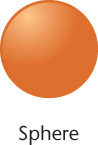
Spheres
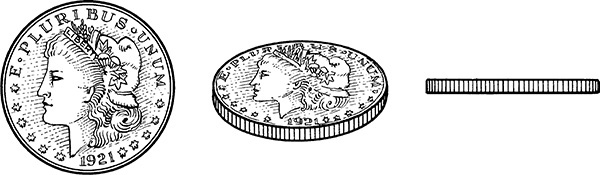
A sphere has a double-curved exterior surface (Figure 3.7). You can think of it as being formed by revolving a circle about one of its diameters, somewhat like spinning a coin. The poles of the sphere are the points at the top and bottom of the sphere that would not move while it was spinning. The axis of the sphere is the term for the line between its poles.
Tori
A torus is shaped like a doughnut (Figure 3.8). Its boundary surface is double curved. You can think of it as being formed by revolving a circle (or other curve) around an axis that is positioned away from (outside) the curve.

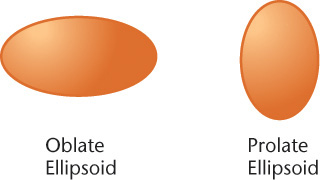
Ellipsoids
An oblate or prolate ellipsoid is shaped like an egg (Figure 3.9). You can think of it as being formed by revolving an ellipse about its minor or major axis, respectively.
Understanding Sketching Techniques
Analyzing Complex Objects
The ability to break down complex shapes into simpler geometric primitives is an essential skill for sketching and modeling objects.
Before you begin to draw the outline of an object, consider its overall shape and the relationships between its parts. Construction lines can help you preserve the overall dimensions of the object as you sketch.
Bear in mind that you should be thinking in terms of basic shapes whether you are sketching by hand or using a CAD program. Because basic curves and straight lines are the basis of many of the objects that people create, practice in creating the basic elements of a drawing will help you sketch with ease.
Essential Shapes
Look for the essential shapes of objects. If you were to make a clay model of an object, what basic shape would you start with? A ball? A box?
Try squinting your eyes and looking at familiar objects. Do you see their shape as a rectangle? A circle? What other basic shapes do you notice when you look at objects this way?
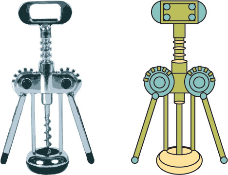
Think about breaking down more complex objects into their simpler geometric shapes as shown in Figure 3.10. You can block in these shapes using construction lines to show their relationships to one another. Then, add details, continuing to pay attention to the spatial relationships between them.

Construction Lines
Artists often begin a sketch by blocking in light guidelines to help them preserve basic shapes and proportions. In technical drawing these are called construction lines (Figure 3.12).
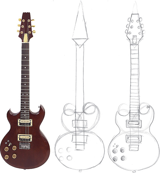
It is often helpful to begin a sketch by describing the object’s main shapes with construction lines, taking some care to accurately represent the relative size and placement of features.
Use the basic shapes as a guide to place key features, then use those main features as a “reference map” to place smaller details. For example, the sixth fret line is about halfway up the rectangular guitar neck.
Throughout this chapter you will use light construction lines to draw circles, arcs, and ellipses. Section 3.4 discusses the process of estimating and maintaining the proportions of an object in further detail.
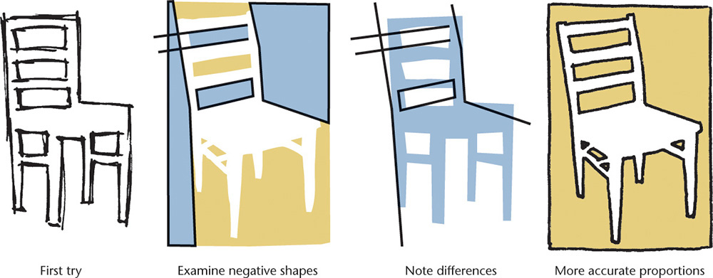
Contours and Negative Space
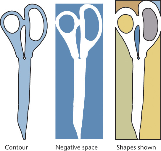
The contours of an object are the main outlines that separate it from the surrounding space. One way to think about the contours of objects is to look at the contrast between the positive and negative space. Positive space is the space occupied by the object. Negative space is the unoccupied space around it.
In Figure 3.13 the space occupied by the contour of a pair of scissors is shown. Note how you can identify specific shapes by looking at the negative space. The individual shapes that make up the negative space are shown in different colors to make them easier for you to see. Some people sketch more accurately when they try to draw the negative space that surrounds the object.
Tip: Practice Drawing Contours
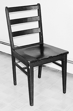
Try sketching the negative spaces that define the shape of a chair. Look at each space as an individual shape. What is the shape of the space between the legs? What is the shape of the space between the rungs and the seat?
Make a sketch of a chair, paying careful attention to sketching the negative spaces of the chair as they really appear. The positive and negative spaces should add up to define the chair.
If you have difficulty, make corrections to your sketch by defining the positive shapes and then check to see if the negative shapes match.
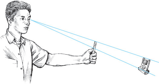
An 8.5″ × 11″ sheet of Plexiglas® (available at most glass stores) is an excellent tool for developing sketching ability. Using a dry-erase marker, hold the Plexiglas up in front of an object and trace the object’s contours on the Plexiglas. If you don’t move, the outline should match the object’s outline exactly. Lower the Plexiglas and look at the orientation of the lines. Are they what you expected?
Try looking at the object and drawing the sketch with the Plexiglas lying on your desktop or knees. Then, raise it and see if your drawing matches the object.
To develop sketching ability, try drawing everyday objects like your toaster, printer, or lamp, as well as exterior and interior views of buildings and equipment.
Viewpoint
As you sketch objects, keep in mind that you want to maintain a consistent viewpoint, as a camera does. This is easier when you are sketching a picture from a book, because you can’t move around the object. When you move, you see a different view of the object depending on where you stand.
Sometimes people have difficulty sketching because they want to show parts of the object that cannot really be seen from a single viewpoint. For example, knowing that the handle of the rubber stamp in Figure 3.14 appears circular from the top, you may be tempted to show it as round, even though it may appear elliptical from your viewpoint.
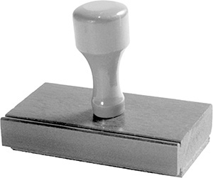
When you are sketching an object pictorially, temporarily set aside your knowledge of the shapes the object is actually made of and carefully examine the shapes you see from a single, static viewpoint. In this type of sketching, instead of trying to envision the object as it is, try only to see it as it looks.
Shading
Adding shading to your sketch can give it a more realistic appearance because it represents the way the actual object would reflect light. Shading doesn’t mean “coloring in.” You may want to shade only the most prominently shadowed areas. First, identify the darkest and lightest areas on an object. If you want, you can shade various middle tones, placed exactly as they look on the object.
In some ways, shading is like doing a drawing within a drawing, because it is a matter of identifying shapes. When you are shading, instead of identifying the shapes of the object’s contours, you are identifying the shape and relative darkness of the shadows.
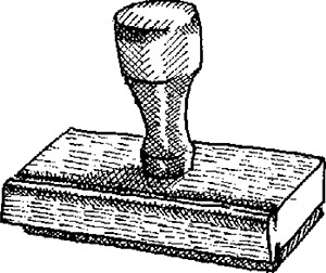
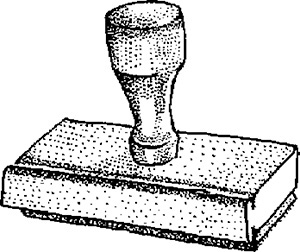
Hatching lines, shown in Figure 3.15, and stippling, shown in Figure 3.16, are commonly used methods to add shading because they are easier to reproduce with a photocopier than continuous-tone pencil shading. In the illustration you can see that shadowed areas are darkened simply by adding more hatching lines or stippling dots.
It is not uncommon for people to draw outlines by hand and add digital shaded fills to a scan of the outline. Another way to make a subject the clear focal point of a drawing is to stylize the shadows. Industrial designers often use markers to add a stylized shadow to their sketches. You can use a straight edge to protect the original sketch from the marker and quickly sketch the shadow (Figure 3.17).
Regardless of how you apply shading, darken the outline to define the shape clearly and boldly. Remember that when you are communicating by using a sketch, its subject should be clear. To make the subject—in this case, a rubber stamp—clear, make it stand out with thick bold contour lines.
Edges and Vertices
Edges
An edge of a solid is formed where two surfaces intersect. Edges are represented in drawings by visible or hidden lines (Figure 3.18).

Vertices
A vertex (plural, vertices) of a solid is formed where three or more surfaces intersect. The end of an edge is a vertex. These vertices or “points” are very useful in defining the locations of the solid object feature that you will sketch (Figure 3.18).
Points and Lines
A point is used to represent a location in space but has no width, height, or depth (Figure 3.19). A point in a drawing is represented by the intersection of two lines (Figure 3.19a), by a short crossbar on a line (Figure 3.19b), or by a small cross (Figure 3.19c). Do not represent points by simple dots on the paper. This makes the drawing look “blobby” and is not as accurate.

A line is used in drawings to represent the edge of a solid object. A straight line is the shortest distance between two points and is commonly referred to simply as a “line.” If the line is indefinite in extent, in a drawing the length is a matter of convenience, and the endpoints are not marked (Figure 3.20a). If the endpoints of the line are significant, they are marked by small drawn crossbars (Figure 3.20b). Other common terms are illustrated in Figures 3.20c to i. Either straight lines or curved lines are parallel if the shortest distance between them remains constant. The common symbol for parallel lines is | |, and for perpendicular lines it is ⊥. Two perpendicular lines may be marked with a “box” as shown in Figure 3.20g. Such symbols may be used on sketches, but not on production drawings.

Angles
An angle is formed by two intersecting lines. A common symbol for angle is ∠.
There are 360 degrees (360°) in a full circle, as shown in Figure 3.21a. A degree is divided into 60 minutes (60′), and a minute is divided into 60 seconds (60″). The angle value 37°26′10″ is read 37 degrees, 26 minutes, and 10 seconds. When minutes alone are indicated, the number of minutes should be preceded by 0°, as in 0°20′. If the minutes value were listed alone without showing the zero value, it might be mistaken for a distance measurement. For example, 20 minutes, 10 seconds written as 20′10″ might be mistaken for 20 feet 10 inches.
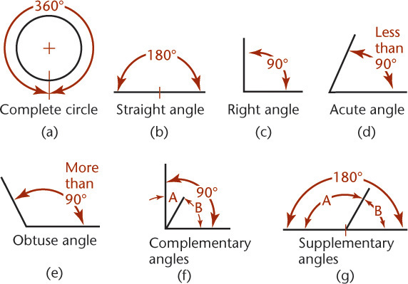
The different kinds of angles are illustrated in Figure 3.21. Two angles are complementary if they total 90° (Figure 3.21f) and are supplementary if they total 180° (Figure 3.21g).
In sketching, most angles can be estimated. Use a protractor if necessary when drawing odd angles.
Drawings and Sketches
The following are important skills to keep in mind for sketches and drawings:
1. Accuracy. No drawing is useful unless it shows the information correctly.
2. Speed. Time is money in industry. Work smarter and learn to use techniques to speed up your sketching and CAD drawings while still producing neat accurate results.
3. Legibility. A drawing is a means of communicating with others, so it must be clear and legible. Give attention to details. Things that may seem picky and small as you are drawing may be significant and save money or even lives when the product is built.
4. Neatness. If a drawing is to be accurate and legible, it must also be clean.
Accuracy Counts: Dizzy Probe Crash

Accuracy and legibility in drawings is serious business, as is demonstrated in this article from New Scientist magazine about the September 2004 Genesis dizzy probe crash. (Photo courtesy of NASA.)
You would think that by now, NASA should be able to tell up from down. Not so in the case of their Genesis space capsule, which crashed into the desert in Utah instead of parachuting gently down so that helicopter stunt pilots could pluck it to safety.
Since its launch in August 2001, the capsule had been collecting precious particles from the solar wind that would have told us something about the composition of the solar system.
But after reentering Earth’s atmosphere on September 8, 2004, Genesis plunged into the ground, and much of its payload was lost.
On October 15, investigators released their preliminary conclusions, blaming the crash on “a design error that involves the orientation of gravity-switch devices.” Huh?
The four small cylindrical switches were designed to sense the reentry and trigger the parachute. But they were drawn upside down in Lockheed Martin’s technical drawings, so they were installed upside down—although NASA’s Michael Ryschkewitsch, who led the investigation, is reluctant to use those exact words. The switches never detected the reentry. Similar devices are installed on another sample-collecting mission called Stardust. Ryschkewitsch believes these were installed the right way up.
(Courtesy of New Scientist magazine.)
Freehand Sketching
Freehand sketches are a helpful way to organize your thoughts and record ideas. They provide a quick, low-cost way to explore various solutions to design problems so that the best choices can be made. Investing too much time in creating a detailed layout before exploring your options through sketches can be costly.
The degree of precision needed in a given sketch depends on its use. Quick sketches to supplement verbal descriptions may be rough and incomplete. Sketches can be used to convey important and precise information when they are clearly drawn and annotated.
Freehand sketching requires only pencil, paper, and eraser. Mastering the techniques in this chapter for showing quick single-view, oblique, perspective, and isometric drawings using good freehand line technique will give you a valuable tool for communicating your ideas.
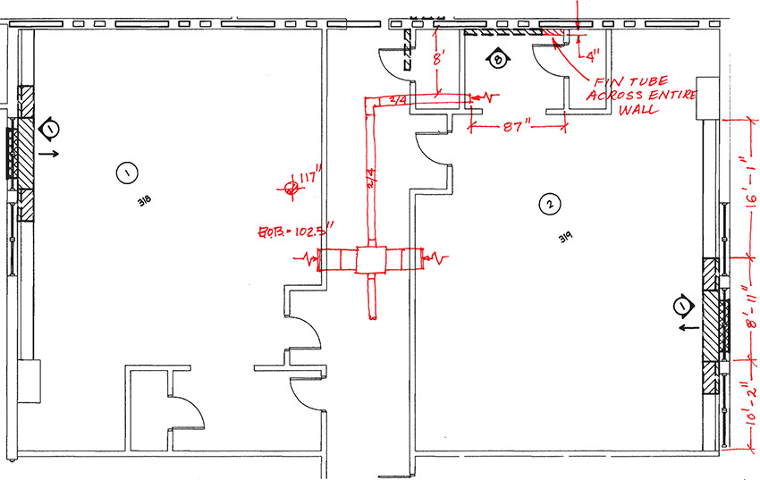
The term freehand sketch does not mean a sloppy drawing. As shown in Figure 3.22, a freehand sketch shows attention to proportion, clarity, and correct line widths. Figure 3.23 shows an as-built drawing with corrected items sketched on the printed CAD drawing.
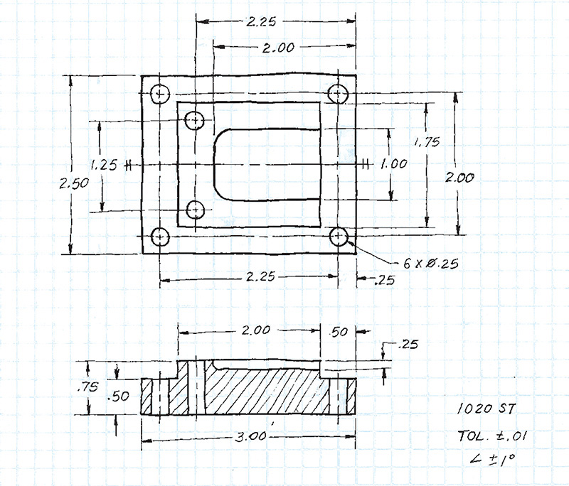
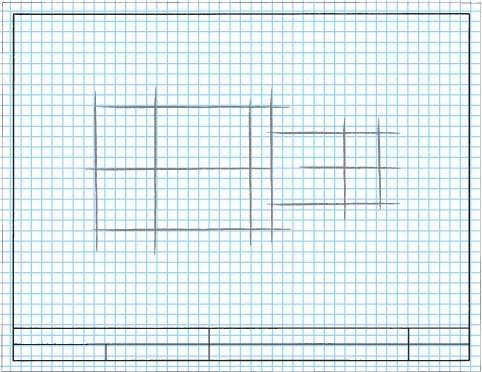
3.22 Sketch on Graph Paper. Sketches are also used to clarify information about changes in design or to provide information on repairing existing equipment.
3.1 Technique of Lines
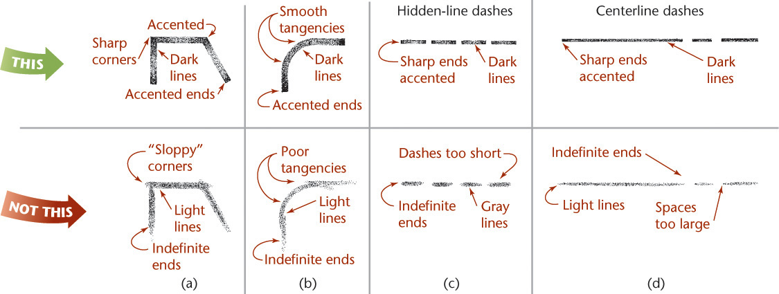
The chief difference between a drawing and a freehand sketch lies in the character or technique of the lines. A good freehand line is not expected to be as rigidly straight or exactly uniform. A good freehand line shows freedom and variety, whereas a line drawn using CAD or instruments should be exact. Still, it is important to distinguish between line patterns to make your drawing legible.
The line patterns in Figure 3.24 are examples of good freehand quality. Figure 3.25 shows examples of good and poor technique.
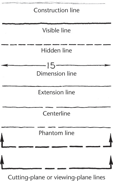
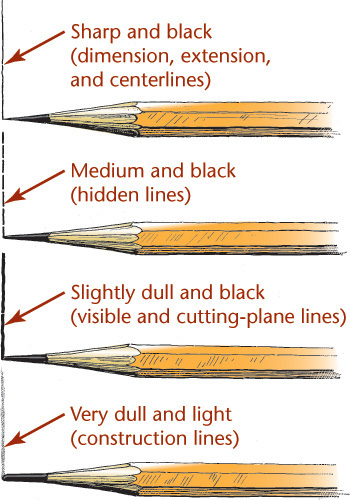
Lineweights
• Make dimension, extension, and centerlines thin, sharp, and black.
• Make hidden lines medium and black.
• Make visible and cutting-plane lines thick and black.
• Make construction lines thick and light.
Tip
Even in freehand drawings, thick lines should be twice the width of thin lines.
Thicknesses do not have to be exact, but there should be an obvious difference between thick and thin lines.
Because visible lines and cutting-plane lines are the two thick line patterns, other lines should be distinctly thinner in comparison.
To draw thick and thin lines freehand, you might like to keep two pencils handy, one that is razor sharp for thin lines and another that is dulled, to create thicker lines.
As the sharp point becomes dulled, switch it with the dull pencil, and sharpen the other, so that there is always one sharp and one dulled point ready to use.
3.2 Sketching Straight Lines
Most of the lines in an average sketch are straight lines. With practice, your straight lines will naturally improve, but these basics may help you improve quickly.
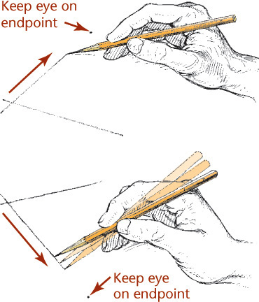
• Hold your pencil naturally, about 1″ back from the point, and approximately at a right angle to the line to be drawn.
• Draw horizontal lines from left to right with a free and easy wrist and arm movement.
• Draw vertical lines downward with a wrist and arm movement.
• Draw curved lines using finger and wrist movements.
Blocking in a Freehand Drawing
Over the years, freehand sketchers have developed all sorts of tricks to improve speed and accuracy. Methods for finding midpoints or quickly blocking in straight vertical and horizontal lines are just a few secrets of the technical sketching craft that can come in handy, even today. When a great idea hits, or you need to sketch quickly at a meeting or on a job site, you might not have access to a CAD system, or even a ruler.
Tips: Drawing Long Freehand Lines
For long freehand lines, make light end marks and lightly sweep your pencil between them, keeping your eye on the mark toward which you are moving. When you are satisfied with the accuracy of your strokes, apply more pressure to make a dark line.
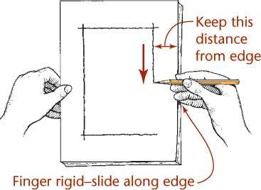
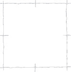
Blocking in a Border Freehand
Hold your hand and pencil rigidly and glide your fingertips along the edge of the paper to maintain a uniform border.
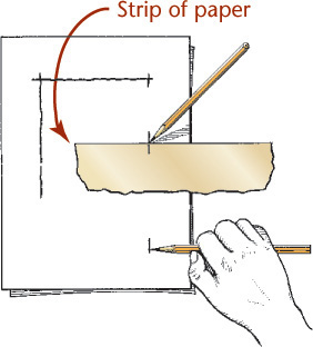
Blocking in a Border Using a Strip of Paper
Mark the distance on the edge of a card or a strip of paper and use it like a ruler to mark at intervals, then draw a final line through the points.
If your line looks like this, you may be gripping your pencil too tightly or trying too hard to imitate mechanical lines.
Slight wiggles are OK as long as the line continues on a straight path.
Occasional very slight gaps are fine and make it easier to draw straight.
Finding a Midpoint Freehand
Use your thumb on your pencil to guess half the distance. Try this distance on the other half. Continue adjusting until you locate the center, then mark it.

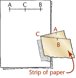
Folding a Paper to Find a Midpoint
Mark the total distance on the edge of a strip of paper, then fold the paper to locate its center at the crease. You can fold one half to find quarter points, and so on.
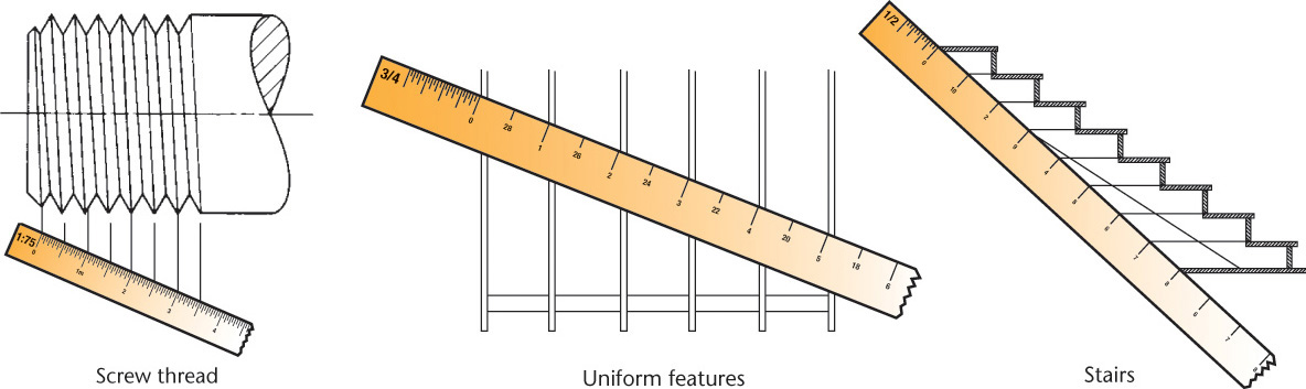
Step by Step: Dividing Lines into Equal or Proportional Parts
Proportional Parts
To divide the given line shown into proportions of (for example) 2, 3, and 4 units:

![]() Draw a vertical construction line at one end of the line you are dividing.
Draw a vertical construction line at one end of the line you are dividing.

![]() Set the zero point of your scale at the other end of the line.
Set the zero point of your scale at the other end of the line.
![]() Swing the scale so the desired unit falls on the vertical line. In this case it will be the 9th unit, because 2 + 3 + 4 = 9.
Swing the scale so the desired unit falls on the vertical line. In this case it will be the 9th unit, because 2 + 3 + 4 = 9.

![]() Draw vertical lines upward from the corresponding scale divisions and mark tiny crossbars on the line as shown.
Draw vertical lines upward from the corresponding scale divisions and mark tiny crossbars on the line as shown.
Equal Parts
If you use uniform divisions for the steps above (every third division, for instance) you will get equal parts. Examples of practical applications for dividing lines equally are shown below.
Calculated Proportions
To divide a line into proportions equal to the square of 1, 2, 3, and 4 (1, 4, 9, and 16), find 16 divisions on your scale.
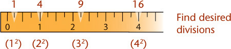
![]() Set the zero point of your scale at the end of the line and draw a light construction line at any convenient angle from one end of the line you are dividing to the appropriate division on the scale. In this case the 4 mark is 16 equal divisions from the 0.
Set the zero point of your scale at the end of the line and draw a light construction line at any convenient angle from one end of the line you are dividing to the appropriate division on the scale. In this case the 4 mark is 16 equal divisions from the 0.
![]() Draw construction lines parallel to the end line through each proportionate scale division.
Draw construction lines parallel to the end line through each proportionate scale division.

Tip: Exaggerating Closely Spaced Parallel Lines
Sometimes it is helpful to exaggerate the distance between closely spaced parallel lines so there is no fill-in when the drawing is reproduced.
Usually this is done to a maximum of 3 mm or .120″. When using CAD it is better to draw the features the actual size and include a detail showing the actual spacing.
3.3 Sketching Circles, Arcs, and Ellipses
Circles
Small circles can be sketched using one or two strokes, without blocking in any construction lines. Circle templates also make it easy to sketch circles of various sizes.
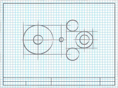
For better looking freehand sketched circles of larger sizes, try the construction methods shown here. Figure 3.26 shows an object with rounded features to sketch using circles, arcs, and ellipses.

3.26 Many objects have rounded features that circles, arcs, and ellipses are used to represent. (Tim Ridley © Dorling Kindersley.)
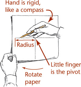
Tip: The Freehand Compass
Using your hand like a compass, you can create circles and arcs with surprising accuracy after a few minutes of practice.
1. Place the tip of your little finger or the knuckle joint of your little finger at the center.
2. “Feed” the pencil out to the radius you want as you would do with a compass.
3. Hold this position rigidly and rotate the paper with your free hand.
Step by Step: Methods for Sketching Circles
Enclosing Square Method
![]() Lightly sketch an enclosing square and mark the midpoint of each side.
Lightly sketch an enclosing square and mark the midpoint of each side.
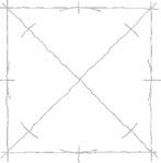
![]() Lightly draw in arcs to connect the midpoints.
Lightly draw in arcs to connect the midpoints.
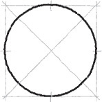
![]() Darken the final circle.
Darken the final circle.
Centerline Method
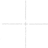
![]() Sketch the two centerlines of the circle.
Sketch the two centerlines of the circle.
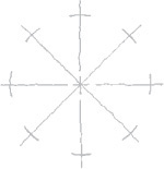
![]() Add light 45° radial lines and sketch light arcs across them at an estimated radius distance from the center.
Add light 45° radial lines and sketch light arcs across them at an estimated radius distance from the center.
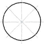
![]() Darken the final circle.
Darken the final circle.
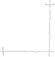
Paper Method

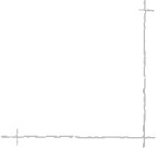
![]() Mark the estimated radius on the edge of a card or scrap of paper and set off from the center as many points as desired.
Mark the estimated radius on the edge of a card or scrap of paper and set off from the center as many points as desired.
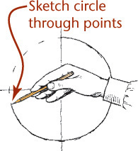
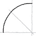
![]() Sketch the final circle through these points.
Sketch the final circle through these points.
Step by Step: Methods for Sketching Arcs
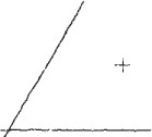
Radius Method
![]() Locate the center of the arc and lightly block in perpendicular lines. Mark off the radius distance along the lines.
Locate the center of the arc and lightly block in perpendicular lines. Mark off the radius distance along the lines.
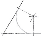
![]() Draw a 45° line through the center point and mark off the radius distance along it.
Draw a 45° line through the center point and mark off the radius distance along it.

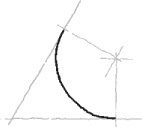
![]() Lightly sketch in the arc as shown. Darken the final arc.
Lightly sketch in the arc as shown. Darken the final arc.
Trammel Method
![]() Locate the center of the arc and lightly block in perpendicular lines. Mark off the radius distance along the lines.
Locate the center of the arc and lightly block in perpendicular lines. Mark off the radius distance along the lines.
![]() Mark the radius distance on a strip of paper and use it as a trammel.
Mark the radius distance on a strip of paper and use it as a trammel.

![]() Lightly sketch in the arc, then darken the final arc.
Lightly sketch in the arc, then darken the final arc.
Tangent Method
Use these steps to draw arcs sketched to points of tangency.
![]() Locate the center of the arc and sketch in the lines to which the arc is tangent.
Locate the center of the arc and sketch in the lines to which the arc is tangent.
![]() Draw perpendiculars from the center to the tangent lines.
Draw perpendiculars from the center to the tangent lines.

![]() Draw in the arc tangent to the lines ending at the perpendicular lines.
Draw in the arc tangent to the lines ending at the perpendicular lines.
![]() Darken in the arc and then darken the lines from the points of tangency.
Darken in the arc and then darken the lines from the points of tangency.
Methods for Sketching Ellipses
Freehand Method
![]() Rest your weight on your upper forearm and move the pencil rapidly above the paper in an elliptical path.
Rest your weight on your upper forearm and move the pencil rapidly above the paper in an elliptical path.
![]() Lower the pencil to draw very light ellipses.
Lower the pencil to draw very light ellipses.
![]() Darken the final ellipse.
Darken the final ellipse.
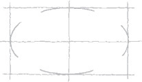
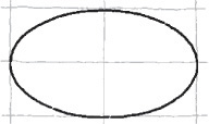
Rectangle Method
![]() Lightly sketch an enclosing rectangle.
Lightly sketch an enclosing rectangle.
![]() Mark the midpoint of each side and sketch light tangent arcs.
Mark the midpoint of each side and sketch light tangent arcs.
![]() Darken in the final ellipse.
Darken in the final ellipse.
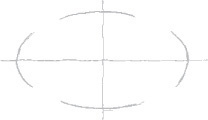
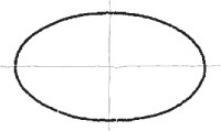
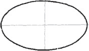
Axes Method
![]() Lightly sketch in the major and minor axes of the ellipse.
Lightly sketch in the major and minor axes of the ellipse.
![]() Mark the distance along the axes and lightly block in the ellipse.
Mark the distance along the axes and lightly block in the ellipse.
![]() Darken the final ellipse.
Darken the final ellipse.
Trammel Method
![]() To sketch accurate ellipses, you can make a trammel.
To sketch accurate ellipses, you can make a trammel.

![]() Mark half the desired length of the minor axis on the edge of a strip of paper (A-B). Using the same starting point, mark half the length of the major axis (A-C). (The measurements will overlap.)
Mark half the desired length of the minor axis on the edge of a strip of paper (A-B). Using the same starting point, mark half the length of the major axis (A-C). (The measurements will overlap.)
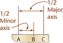
![]() Line up the last two trammel points (B and C) on the axes and mark a small dot at the location of the first point (A).
Line up the last two trammel points (B and C) on the axes and mark a small dot at the location of the first point (A).

![]() Move the trammel to different positions, keeping B and C on the axes, and mark more points at A. Sketch the final ellipse through the points.
Move the trammel to different positions, keeping B and C on the axes, and mark more points at A. Sketch the final ellipse through the points.
Sketching Arcs
Sketching arcs is similar to sketching circles. In general, it is easier to hold your pencil on the inside of the curve. Look closely at the actual geometric constructions and carefully approximate points of tangency so that the arc touches a line or other entity at the right point.
Sketching Ellipses
If a circle is tipped away from your view, it appears as an ellipse. Figure 3.27 shows a coin viewed so that it appears as an ellipse. You can learn to sketch small ellipses with a free arm movement similar to the way you sketch circles, or you can use ellipse templates to help you easily sketch ellipses. These templates are usually grouped according to the amount a circular shape would be rotated to form the ellipse. They provide a number of sizes of ellipses on each template but usually include only one or two typical rotations.
3.4 Maintaining Proportions
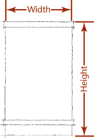
Sketches are not usually made to a specific scale, although it can be handy to do so at times. The size of the sketch depends on its complexity and the size of the paper available. The most important rule in freehand sketching is to keep the sketch in proportion, which means to accurately represent the size and position of each part in relation to the whole. No matter how brilliant the technique or how well drawn the details, if the proportions are off, the sketch will not look right.
To maintain proportions, first determine the relative proportions of height to width and lightly block them in. You can mark a unit on the edge of a strip of paper or use your pencil (as in Figure 3.28) to gauge how many units wide and high the object is. Grid paper can help you maintain proportions by providing a ready-made scale (by counting squares). As you block in the medium-size areas, and later as you add small details, compare each new distance with those already established.
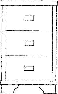
Step by Step: Maintaining Proportions in a Sketch
![]() If you are working from a given picture, such as this utility cabinet, first establish the relative width compared to the height. One way is to use the pencil as a measuring stick. In this case, the height is about 1-3/4 times the width.
If you are working from a given picture, such as this utility cabinet, first establish the relative width compared to the height. One way is to use the pencil as a measuring stick. In this case, the height is about 1-3/4 times the width.

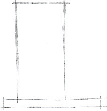
![]() Sketch the enclosing rectangle in the correct proportion. This sketch is to be slightly larger than the given picture.
Sketch the enclosing rectangle in the correct proportion. This sketch is to be slightly larger than the given picture.
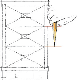
![]() Divide the available drawer space into three parts with the pencil by trial. Hold your pencil about where you think one third will be and then try that measurement. If it is too short or long, adjust the measurement and try again. Sketch light diagonals to locate centers of the drawers and block in drawer handles. Sketch all remaining details.
Divide the available drawer space into three parts with the pencil by trial. Hold your pencil about where you think one third will be and then try that measurement. If it is too short or long, adjust the measurement and try again. Sketch light diagonals to locate centers of the drawers and block in drawer handles. Sketch all remaining details.
![]() Darken all final lines, making them clean, thick, and black.
Darken all final lines, making them clean, thick, and black.
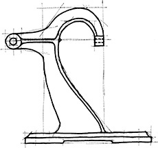
Step by Step: How to Block in an Irregular Object
![]() Capture the main proportions with simple lines.
Capture the main proportions with simple lines.
![]() Block in the general sizes and direction of flow of curved shapes.
Block in the general sizes and direction of flow of curved shapes.

![]() Lightly block in additional details.
Lightly block in additional details.

![]() Darken the lines of the completed sketch.
Darken the lines of the completed sketch.
Step by Step: Geometric Methods for Sketching Plane Figures
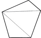
Sketching a Polygon by the Triangle Method
![]() Divide the polygon into triangles as shown. Use the triangles as a visual aid to sketch the shape.
Divide the polygon into triangles as shown. Use the triangles as a visual aid to sketch the shape.
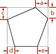
Sketching a Polygon by the Rectangle Method
![]() Imagine a rectangle drawn around the polygon as shown.
Imagine a rectangle drawn around the polygon as shown.
![]() Sketch the rectangle and then locate the vertices of the polygon (points a, b, c, and so on) along the sides of the rectangle.
Sketch the rectangle and then locate the vertices of the polygon (points a, b, c, and so on) along the sides of the rectangle.
![]() Join the points to complete the shape.
Join the points to complete the shape.
Visual Aids for Sketching Irregular Figures
![]() Visualize shapes made up of rectangular and circular forms by enclosing those features in rectangles.
Visualize shapes made up of rectangular and circular forms by enclosing those features in rectangles.
![]() Determine where the centers of arcs and circles are located relative to the rectangles as shown.
Determine where the centers of arcs and circles are located relative to the rectangles as shown.
![]() Sketch the features inside the rectangular shapes you have lightly blocked in and darken the final lines.
Sketch the features inside the rectangular shapes you have lightly blocked in and darken the final lines.

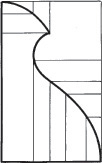
Creating Irregular Shapes by Offset Measurements
![]() Enclose the shape in a rectangle.
Enclose the shape in a rectangle.
![]() Use the sides of the rectangle as a reference to make measurements that locate points along the curve.
Use the sides of the rectangle as a reference to make measurements that locate points along the curve.
Enlarging Shapes Using a Grid of Squares
![]() Complex curved shapes can be copied, enlarged, or reduced by hand, if necessary.
Complex curved shapes can be copied, enlarged, or reduced by hand, if necessary.
![]() Draw or overlay a grid of squares on the original drawing.
Draw or overlay a grid of squares on the original drawing.
![]() To enlarge, draw the containing rectangle and grid of squares at the desired percentage and transfer the lines of the shape through the corresponding points in the new set of squares.
To enlarge, draw the containing rectangle and grid of squares at the desired percentage and transfer the lines of the shape through the corresponding points in the new set of squares.

3.5 One-View Drawings
Frequently, a single view supplemented by notes and dimensions is enough information to describe the shape of a relatively simple object.
In Figure 3.29, one view of the shim plus a note indicating the thickness as 0.25 mm is sufficient.
Nearly all shafts, bolts, screws, and similar parts should be represented by single views in this way.
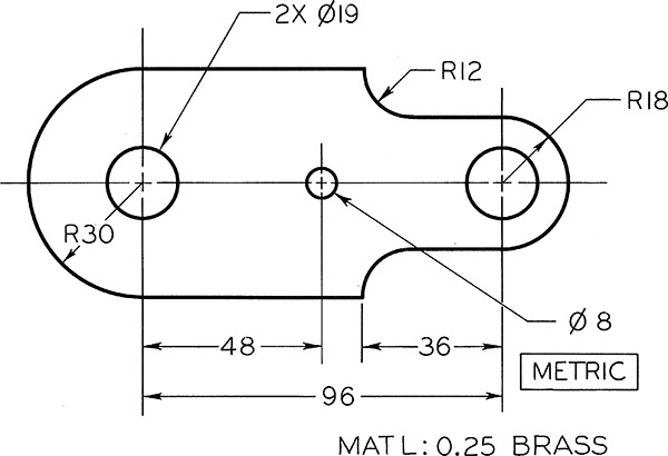
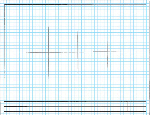
Step by Step: Sketching a Single-View Drawing
Follow the steps to sketch the single-view drawing of the shim shown in Figure 3.29.
![]() Lightly sketch the centerlines for the overall width and height of the part. Estimate overall proportions by eye, or if you know the dimensions, use a measuring scale to sketch accurately sized views. Space the enclosing rectangle equally from the margins of the sheet.
Lightly sketch the centerlines for the overall width and height of the part. Estimate overall proportions by eye, or if you know the dimensions, use a measuring scale to sketch accurately sized views. Space the enclosing rectangle equally from the margins of the sheet.
![]() Block in all details lightly, keeping the drawing proportions in mind. Use techniques introduced in this chapter to help you.
Block in all details lightly, keeping the drawing proportions in mind. Use techniques introduced in this chapter to help you.
![]() Locate the centers of circles and arcs. Block in where they will fit using rectangles. Then, sketch all arcs and circles lightly.
Locate the centers of circles and arcs. Block in where they will fit using rectangles. Then, sketch all arcs and circles lightly.
![]() Darken your final lines.
Darken your final lines.

![]() Add annotations to the drawing using neat lettering. Fill in the title block or title strip. Note the scale for the sketch if applicable. If not, letter NONE in the Scale area of the title block.
Add annotations to the drawing using neat lettering. Fill in the title block or title strip. Note the scale for the sketch if applicable. If not, letter NONE in the Scale area of the title block.
3.6 Pictorial Sketching
A pictorial sketch represents a 3D object on a 2D sheet of paper by orienting the object so you can see its width, height, and depth in a single view.
Pictorial sketches are used frequently during the ideation phase of engineering design to record ideas quickly and communicate them to others. Their similarity to how the object is viewed in the real world makes them useful for communicating engineering designs to nonengineers. Later in the design process, pictorial drawings are often used to show how parts fit together in an assembly and, in part catalogs and manuals, to make it easy to identify the objects.
This chapter examines three common methods used to sketch pictorials: isometric sketching, which is a subtype of the general category of axonometric projection, oblique sketching, and perspective sketching. Figure 3.30 shows perspective, isometric, and oblique sketches of a stapler. Figure 3.31 shows pictorial sketches for backpack concepts.

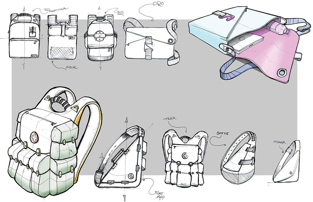
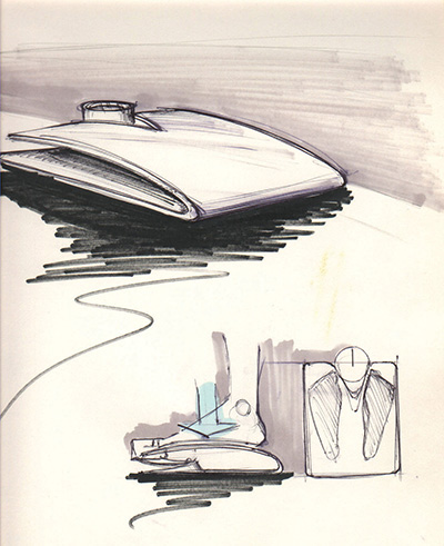
3.31 Pictorial sketching is used frequently to convey preliminary design ideas, as in these backpack concept sketches. (Courtesy of André Cotan.)
Each of the pictorial methods differs in the way points on the object are located on the 2D viewing plane (the piece of paper).
A perspective sketch presents the most realistic looking view. It shows the object much as it would appear in a photograph—portions of the object that are farther from the viewer appear smaller, and lines recede into the distance.
An axonometric sketch is drawn so that lines do not recede into the distance but remain parallel. This makes isometric views easy to sketch but takes away somewhat from the realistic appearance.
An oblique sketch shows the front surface of the object looking straight on and is easy to create, but it presents the least realistic representation because the depth of the object appears to be out of proportion.
Various types of pictorial drawings are used extensively in catalogs, sales literature, and technical work. They are often used in patent drawings; in piping diagrams; in machine, structural, architectural design, and in furniture design; and for ideation sketching. The sketches for a wooden shelf in Figure 3.32 are examples of axonometric, orthographic, and perspective sketches.
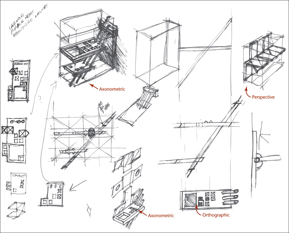
3.32 Sketches for a Wooden Shelf Using Axonometric, Orthographic, and Perspective Drawing Techniques. The axonometric projections in this sketch are drawn in isometric. (Courtesy of Douglas Wintin.)
In axonometric and oblique drawings, distant features are not shown proportionately smaller, the way they appear in a photograph or to our vision. Edges that are parallel on the object always appear parallel in an axonometric view. The most common axonometric projection is isometric, which means “equal measure.” When a cube is drawn in isometric, the axes are equally spaced (120° apart). Though not as realistic as perspective drawings, isometric drawings are much easier to draw. CAD software often displays the results of 3D models on the screen as isometric projections. Some CAD software allows you to choose between isometric, axonometric views (see Figure 3.35 for examples), or perspective representation of your 3D models on the 2D computer screen. In sketching, dimetric and trimetric sometimes produce a better view than isometric but take longer to draw and are therefore used less frequently.
3.7 Projection Methods
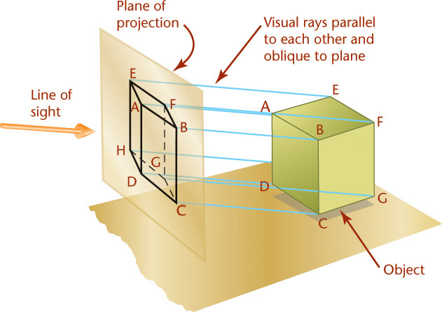
The four principal types of projection are shown in Figure 3.33. All except the regular multiview projection (Figure 3.33a) are pictorial types, because they show several sides of the object in a single view. In both multiview projection and axonometric projection, the visual rays are parallel to each other and perpendicular to the plane of projection. Both are types of orthographic projection (Figures 3.33a and 3.33b).
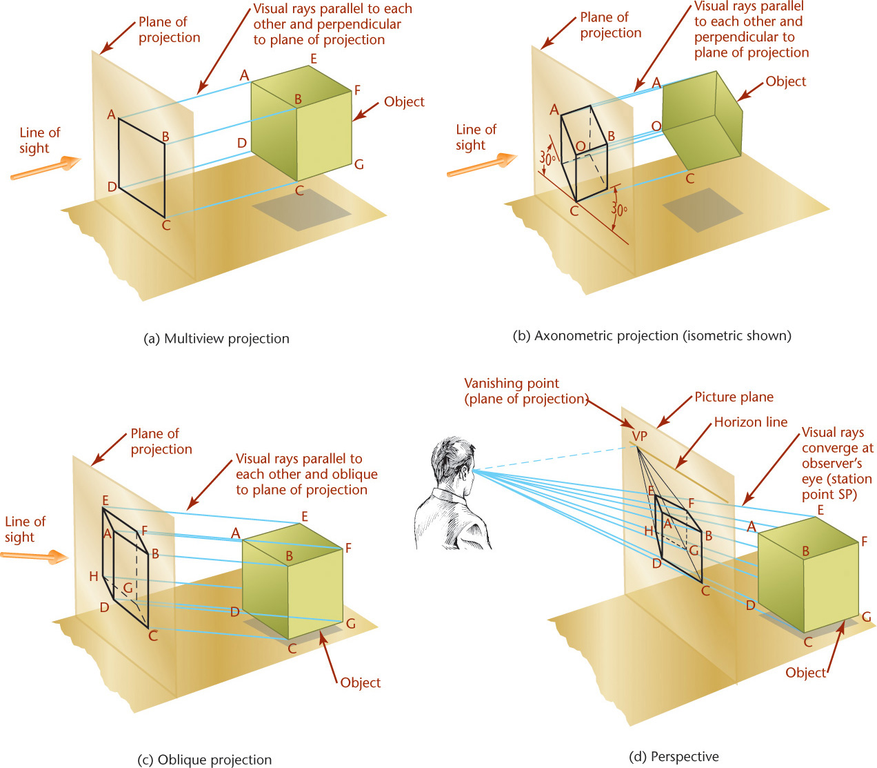
In oblique projection (Figure 3.33c), the visual rays are parallel to each other but at an angle other than 90° to the plane of projection.
In perspective (Figure 3.33d), the visual rays extend from the observer’s eye, or station point (SP), to all points of the object to form a “cone of rays,” so that the portions of the object that are farther away from the observer appear smaller than the closer portions of the object.
3.8 Axonometric Projection
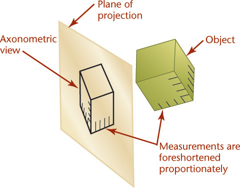
The feature that distinguishes axonometric projection from multiview projection is the inclined position of the object with respect to the planes of projection. When a surface or edge of the object is not parallel to the plane of projection, it appears foreshortened. When an angle is not parallel to the plane of projection, it appears either smaller or larger than the true angle.
To create an axonometric view, the object is tipped to the planes of projection so that principal faces, such as the top, side, and front, show in a single view. This produces a pictorial drawing that is easy to visualize, but because the principal edges and surfaces of the object are inclined to the plane of projection, the lengths of the lines are foreshortened. The angles between surfaces and edges appear either larger or smaller than the true angle. There are an infinite variety of ways that the object may be oriented with respect to the plane of projection.
The degree of foreshortening of any line depends on its angle to the plane of projection. The greater the angle, the greater the foreshortening. Once the degree of foreshortening is determined for each of the three edges of the cube that meet at one corner, scales can be easily constructed for measuring along these edges or any other edges parallel to them (Figure 3.34).
Use the three edges of the cube that meet at the corner nearest your view as the axonometric axes. Figure 3.35 shows three axonometric projections.
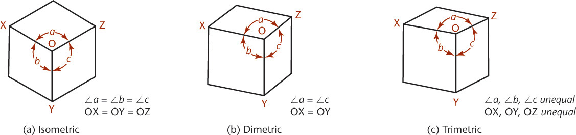
Isometric projection (Figure 3.35a) has equal foreshortening along each of the three axis directions.
Dimetric projection (Figure 3.35b) has equal foreshortening along two axis directions and a different amount of foreshortening along the third axis. This is because it is not tipped an equal amount to all the principal planes of projection.
Trimetric projection (Figure 3.35c) has different foreshortening along all three axis directions. This view is produced by an object that is unequally tipped to all the planes of projection.
Axonometric Projections and 3D Models
When you create a 3D CAD model, the object is stored so that vertices, surfaces, and solids are all defined relative to a 3D coordinate system. You can rotate your view of the object to produce a view from any direction. However, your computer screen is a flat surface, like a sheet of paper. The CAD software uses similar projection to produce the view transformations, creating the 2D view of the object on your computer screen. Most 3D CAD software provides a variety of preset isometric viewing directions to make it easy for you to manipulate the view. Some CAD software also allows for easy perspective viewing on screen.
After rotating the object you may want to return to a preset typical axonometric view like one of the examples shown in Figure 3.36.
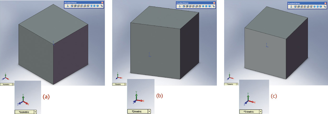
3.36 (a) Isometric View of a 1″ Cube Shown in SolidWorks; (b) Dimetric View; (c) Trimetric View (Images courtesy of ©2016 Dassault Systèmes SolidWorks Corporation.)
3.9 Isometric Projection
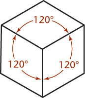
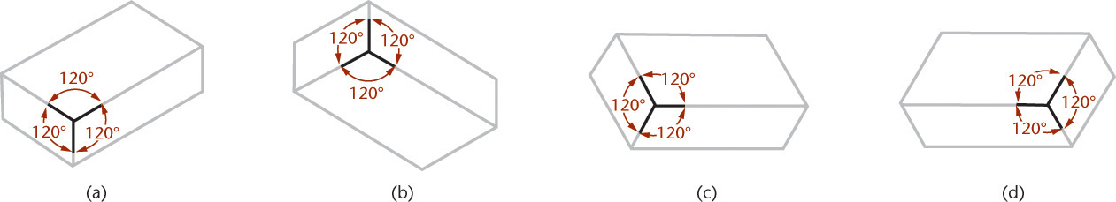
In an isometric projection, all angles between the axonometric axes are equal. To produce an isometric projection, you orient the object so that its principal edges (or axes) make equal angles with the plane of projection and are therefore foreshortened equally. Oriented this way, the edges of a cube are projected so that they all measure the same and make equal angles (of 120°) with each other, as shown in Figure 3.37.
Isometric Axes
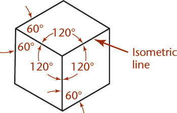
The projections of the edges of a cube make angles of 120° with each other. You can use these as the isometric axes from which to make measurements. Any line parallel to one of these is called an isometric line. The angles in the isometric projection of the cube are either 120° or 60°, and all are projections of 90° angles. In an isometric projection of a cube, the faces of the cube, and any planes parallel to them, are called isometric planes. See Figure 3.38.
Nonisometric Lines
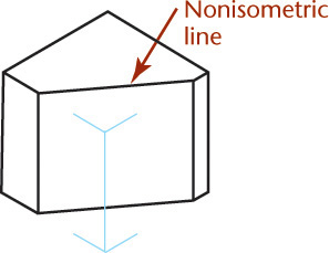
Lines of an isometric drawing that are not parallel to the isometric axes are called nonisometric lines (Figure 3.39). Only lines of an object that are drawn parallel to the isometric axes are equally foreshortened. Nonisometric lines are drawn at other angles and are not equally foreshortened. Therefore the lengths of features along nonisometric lines cannot be measured directly with a scale.
Isometric Scales
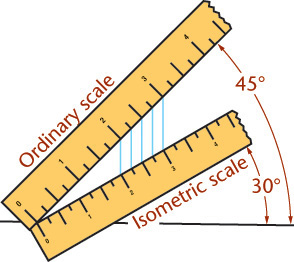
An isometric scale can be used to draw correct isometric projections. All distances in this scale are 2/3 × true size, or approximately 80% of true size. Figure 3.40a shows an isometric scale. More commonly, an isometric sketch or drawing is created using a standard scale, as in Figure 3.40b, disregarding the foreshortening that the tipped surfaces would produce in a true projection. Figure 3.40c shows an isometric view of a 10″ cube modeled in 3D. When measured parallel to the view, the length appears to be 8.1650 due to the foreshortening (near 80% of the actual size).

Tip: Making an Isometric Scale
You can make an isometric scale from a strip of paper or cardboard by placing an ordinary scale at 45° to a horizontal line and the paper (isometric) scale at 30° to the horizontal line. To mark the increments on the isometric scale, draw straight lines (perpendicular to the horizontal line) from the division lines on the ordinary scale.
Alternatively, you can approximate an isometric scale. Scaled measurements of 9″ = 1′–0, or three-quarter-size scale (or metric equivalent) can be used as an approximation.
3.10 Isometric Drawings
When you make a drawing using foreshortened measurements, or when the object is actually projected on a plane of projection, it is called an isometric projection (Figure 3.40a). When you make a drawing using the full-length measurements of the actual object, it is an isometric sketch or isometric drawing (Figure 3.40b) to indicate that it lacks foreshortening.
The isometric drawing is about 25% larger than the isometric projection, but the pictorial value is obviously the same in both. Because isometric sketches are quicker (because you can use the actual measurements), they are much more commonly drawn.
Tip
Some CAD software will notify you about the lack of foreshortening in isometric drawings (or allow you to select for it) when you print or save them.
Positions of the Isometric Axes
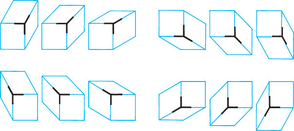
The first step in making an isometric drawing is to decide along which axis direction to show the height, width, and depth, respectively. Figure 3.41 shows four different orientations that you might start with to create an isometric drawing of the block shown. Each is an isometric drawing of the same block, but with a different corner facing your view. These are only a few of many possible orientations.
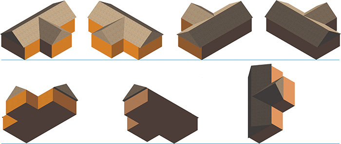
3.42 Isometric Options. These views of a simple model of a house are all isometric, but some show the features best.
You may orient the axes in any desired position, but the angle between them must remain 120°. In selecting an orientation for the axes, choose the position from which the object is usually viewed, or determine the position that best describes the shape of the object, or better yet, both.
If the object is a long part, it will look best with the long axis oriented horizontally.
3.11 Making an Isometric Drawing
Rectangular objects are easy to draw using box construction, which consists of imagining the object enclosed in a rectangular box whose sides coincide with the main faces of the object. For example, imagine the object shown in the two views in the Step by Step feature at right enclosed in a construction box, then locate the features along the edges of the box as shown.
The Step by Step feature on the next page shows how to construct an isometric drawing of an object composed of all “normal” surfaces. Normal is used technically to mean “at right angles.” A normal surface is any surface that is parallel to the sides of the box. Notice that all measurements are made parallel to the main edges of the enclosing box—that is, parallel to the isometric axes. No measurement along a nonisometric line can be measured directly with the scale, as these lines are not foreshortened equally to the normal lines. Start at any one of the corners of the bounding box and draw along the isometric axis directions.
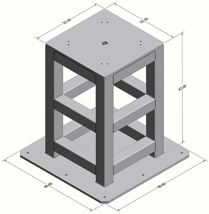
3.43 Isometric drawings are not typically dimensioned. When they are, the dimensions should appear in the same plane as the isometric axes and read from the bottom of the sheet or aligned in the isometric planes. (Courtesy of Brandon Wold.)
Step by Step: Box Construction
Follow these steps to create an isometric sketch of a rectangular object.
![]() Lightly draw the overall dimensions of the box.
Lightly draw the overall dimensions of the box.
![]() Draw the irregular features relative to the sides of the box.
Draw the irregular features relative to the sides of the box.
![]() Darken the final lines.
Darken the final lines.
Step by Step: Drawing Normal Surfaces in Isometric
Follow these steps to create an isometric drawing of the object shown below, which has normal surfaces only.
![]() Select axes along which to block in height, width, and depth dimentions.
Select axes along which to block in height, width, and depth dimentions.

![]() Locate main areas to be removed from the overall block. Lightly sketch along isometric axes to define portion to be removed.
Locate main areas to be removed from the overall block. Lightly sketch along isometric axes to define portion to be removed.
![]() Lightly block in any remaining portions to be removed through the whole block.
Lightly block in any remaining portions to be removed through the whole block.
![]() Lightly block in features to be removed fom the remaining shape along isometric axes.
Lightly block in features to be removed fom the remaining shape along isometric axes.

![]() Darken final lines.
Darken final lines.
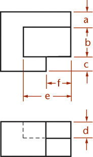
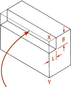
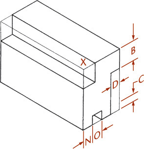
3.12 Offset Location Measurements
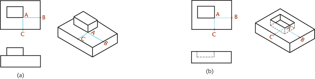
Use the method shown in Figures 3.44a and b to locate points with respect to each other. First, draw the main enclosing block, then draw the offset lines (CA and BA) full size in the isometric drawing to locate corner A of the small block or rectangular recess. These measurements are called offset measurements. Because they are parallel to edges of the main block in the multiview drawings, they will be parallel to the same edges in the isometric drawings (using the rule of parallelism).
Step by Step: Drawing Nonisometric Lines
How to Draw Nonisometric Lines
The inclined lines BA and CA are shown true length in the top view (54 mm), but they are not true length in the isometric view. To draw these lines in the isometric drawing, use a construction box and offset measurements.

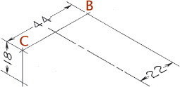
![]() Directly measure dimensions that are along isometric lines (in this case, 44 mm, 18 mm, and 22 mm).
Directly measure dimensions that are along isometric lines (in this case, 44 mm, 18 mm, and 22 mm).
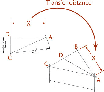
![]() Because the 54 mm dimension is not along an isometric axis, it cannot be used to locate point A.
Because the 54 mm dimension is not along an isometric axis, it cannot be used to locate point A.
Use trigonometry or draw a line parallel to the isometric axis to determine the distance to point A.
Because this dimension is parallel to an isometric axis, it can be transferred to the isometric.
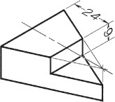
![]() The dimensions 24 mm and 9 mm are parallel to isometric lines and can be measured directly.
The dimensions 24 mm and 9 mm are parallel to isometric lines and can be measured directly.
Tip
To convince yourself that nonisometric lines will not be true length in the isometric drawing, use a scrap of paper and mark the distance BA (Step 2) and then compare it with BA on the given top view. Do the same for line CA. You will see that BA is shorter and CA is longer in the isometric than the corresponding lines in the given views.
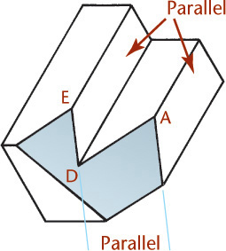
Step by Step: Drawing Oblique Surfaces in Isometric
![]() Find the intersections of the oblique surfaces with the isometric planes. Note that for this example, the oblique plane contains points A, B, and C.
Find the intersections of the oblique surfaces with the isometric planes. Note that for this example, the oblique plane contains points A, B, and C.
![]() To draw the plane, extend line AB to X and Y, in the same isometric plane as C. Use lines XC and YC to locate points E and F.
To draw the plane, extend line AB to X and Y, in the same isometric plane as C. Use lines XC and YC to locate points E and F.

![]() Draw AD and ED using the rule, “Parallel edges on a part will appear parallel in any axonometric view.” Because the inclined surface is planar and the surfaces it intersects are parallel to each other, the edges that lie in those planes will also be parallel.
Draw AD and ED using the rule, “Parallel edges on a part will appear parallel in any axonometric view.” Because the inclined surface is planar and the surfaces it intersects are parallel to each other, the edges that lie in those planes will also be parallel.
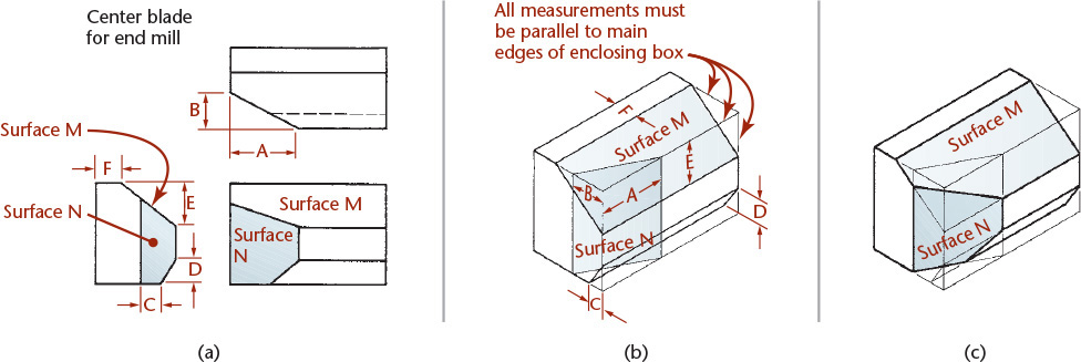
Isometric Drawings of Inclined Surfaces
Figure 3.45 shows how to construct an isometric drawing of an object that has some inclined surfaces and oblique edges. Notice that inclined surfaces are located by offset or coordinate measurements along the isometric lines. For example, dimensions E and F are measured to locate the inclined surface M, and dimensions A and B are used to locate surface N.
3.13 Hidden Lines and Centerlines
Hidden lines in a drawing represent the edges where surfaces meet but are not directly visible. Hidden lines are omitted from pictorial drawings unless they are needed to make the drawing clear. Figure 3.46 shows a case in which hidden lines are needed because a projecting part cannot be clearly shown without them. Sometimes it is better to include an isometric view from another direction than to try to show hidden features with hidden lines. You will learn more about hidden lines in Chapter 6.
Draw centerlines locating the center of a hole only if they are needed to indicate symmetry or for dimensioning. In general, use centerlines sparingly in isometric drawings. If in doubt, leave them out, as too many centerlines will look confusing.
3.14 Angles in Isometric
Angles project true size only when the plane containing the angle is parallel to the plane of projection. An angle may project to appear larger or smaller than the true angle depending on its position.
Because the various surfaces of the object are usually inclined to the front plane of projection, they generally will not be projected true size in an isometric drawing.
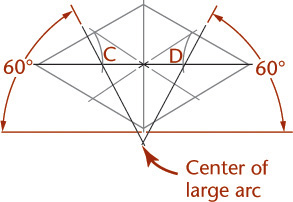
Step by Step: How to Draw Angles in Isometric
The multiview drawing at left shows three 60° angles. None of the three angles will be 60° in the isometric drawing.
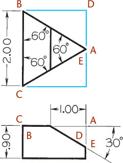
![]() Lightly draw an enclosing box using the given dimensions, except for dimension X, which is not given.
Lightly draw an enclosing box using the given dimensions, except for dimension X, which is not given.
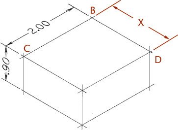
![]() To find dimension X, draw triangle BDA from the top view full size, as shown.
To find dimension X, draw triangle BDA from the top view full size, as shown.
![]() Transfer dimension X to the isometric to complete the enclosing box. Find dimension Y by a similar method and then transfer it to the isometric.
Transfer dimension X to the isometric to complete the enclosing box. Find dimension Y by a similar method and then transfer it to the isometric.

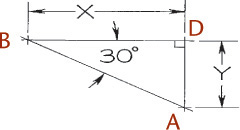
![]() Complete the isometric by locating point E by using dimension K, as shown. A regular protractor cannot be used to measure angles in isometric drawings. Convert angular measurements to linear measurements along isometric axis lines.
Complete the isometric by locating point E by using dimension K, as shown. A regular protractor cannot be used to measure angles in isometric drawings. Convert angular measurements to linear measurements along isometric axis lines.
Tip: Checking Isometric Angles
To convince yourself that none of the angles will be 60°, measure each angle in the isometric in the figure above with a protractor or scrap of paper and note the angle compared with the true 60°. None of the angles shown are the same in the isometric drawing. Two are smaller and one is larger than 60°.
Estimating 30° Angles
If you are sketching on graph paper and estimating angles, an angle of 30° is roughly a rise of 1 to a run of 2.
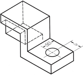
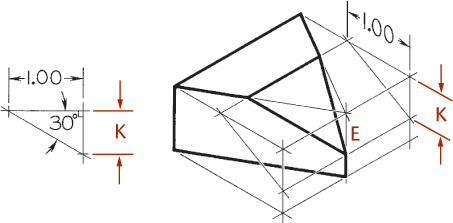
3.15 Irregular Objects
You can use the construction box method to draw objects that are not rectangular (Figure 3.47). Locate the points of the triangular base by offsetting a and b along the edges of the bottom of the construction box. Locate the vertex by offsetting lines OA and OB using the top of the construction box.
Tip
It is not always necessary to draw the complete construction box as shown in Figure 3.47b. If only the bottom of the box is drawn, the triangular base can be constructed as before. The orthographic projection of the vertex O’ on the base can be drawn using offsets O’A and O’B, as shown, and then the vertical line O’O can be drawn, using measurement C.
Tennis Ball (Factory Reject) (Excerpted from Droodles – The Classic Collection by Roger Price ©2000 by Tallfellow Press. Used by permission. All rights reserved.)
3.16 Curves in Isometric
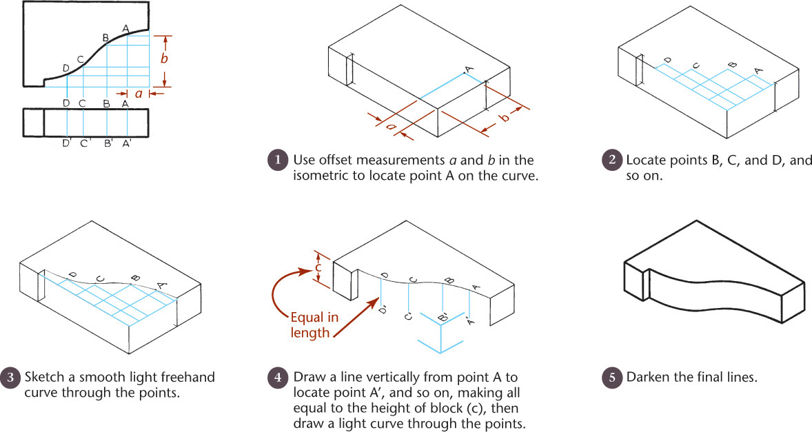
You can draw curves in isometric using a series of offset measurements similar to those discussed in Section 3.12. Select any desired number of points at random along the curve in the given top view, such as points A, B, and C in Figure 3.48. Choose enough points to accurately locate the path of the curve (the more points, the greater the accuracy). Draw offset grid lines from each point parallel to the isometric axes and use them to locate each point in the isometric drawing as in the example shown in Figure 3.48.
3.17 True Ellipses in Isometric
If a circle lies in a plane that is not parallel to the plane of projection, the circle projects as an ellipse. The ellipse can be constructed using offset measurements.
Step by Step: Drawing An Isometric Ellipse by Offset Measurements
Random-Line Method
![]() Draw parallel lines spaced at random across the circle.
Draw parallel lines spaced at random across the circle.
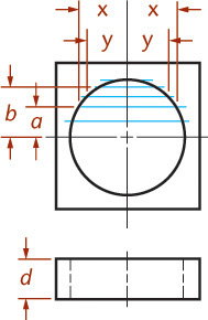
![]() Transfer these lines to the isometric drawing. Where the hole exits the bottom of the block, locate points by measuring down a distance equal to the height d of the block from each of the upper points. Draw the ellipse, part of which will be hidden, through these points. Darken the final drawing lines.
Transfer these lines to the isometric drawing. Where the hole exits the bottom of the block, locate points by measuring down a distance equal to the height d of the block from each of the upper points. Draw the ellipse, part of which will be hidden, through these points. Darken the final drawing lines.

Eight-Point Method
![]() Enclose the given circle in a square, and draw diagonals. Draw another square through the points of intersection of the diagonals and the circle as shown.
Enclose the given circle in a square, and draw diagonals. Draw another square through the points of intersection of the diagonals and the circle as shown.
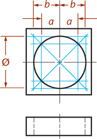
![]() Draw this same construction in the isometric, transferring distances a and b. (If more points are desired, add random parallel lines, as above.) The centerlines in the isometric are the conjugate diameters of the ellipse. The 45° diagonals coincide with the major and minor axes of the ellipse. The minor axis is equal in length to the sides of the inscribed square.
Draw this same construction in the isometric, transferring distances a and b. (If more points are desired, add random parallel lines, as above.) The centerlines in the isometric are the conjugate diameters of the ellipse. The 45° diagonals coincide with the major and minor axes of the ellipse. The minor axis is equal in length to the sides of the inscribed square.
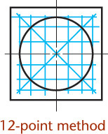
When more accuracy is required, divide the circle into 12 equal parts, as shown.
Nonisometric Lines
If a curve lies in a nonisometric plane, not all offset measurements can be applied directly. The elliptical face shown in the auxiliary view lies in an inclined nonisometric plane.
![]() Draw lines in the orthographic view to locate points.
Draw lines in the orthographic view to locate points.

![]() Enclose the cylinder in a construction box and draw the box in the isometric drawing. Draw the base using offset measurements, and construct the inclined ellipse by locating points and drawing the final curve through them.
Enclose the cylinder in a construction box and draw the box in the isometric drawing. Draw the base using offset measurements, and construct the inclined ellipse by locating points and drawing the final curve through them.
Measure distances parallel to an isometric axis (a, b, etc.) in the isometric drawing on each side of the centerline X–X. Project those not parallel to any isometric axis (e, f, etc.) to the front view and down to the base, then measure along the lower edge of the construction box, as shown.

![]() Darken final lines.
Darken final lines.

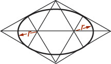
3.18 Orienting Ellipses in Isometric Drawings
Figure 3.49 shows four-center ellipses constructed on the three visible faces of a cube. Note that all the diagonals are horizontal or at 60° with horizontal. Realizing this makes it easier to draw the shapes.

Approximate ellipses such as these, constructed from four arcs, are accurate enough for most isometric drawings. The four-center method can be used only for ellipses in isometric planes. Earlier versions of CAD software, such as AutoCAD Release 10, used this method to create the approximate elliptical shapes available in the software. Current releases use an accurate ellipse.
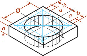
Step by Step: Drawing a Four-Center Ellipse
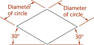
![]() Draw or imagine a square enclosing the circle in the multiview drawing. Draw the isometric view of the square (an equilateral parallelogram with sides equal to the diameter of the circle).
Draw or imagine a square enclosing the circle in the multiview drawing. Draw the isometric view of the square (an equilateral parallelogram with sides equal to the diameter of the circle).
![]() Mark the midpoint of each line and draw a perpendicular line from each.
Mark the midpoint of each line and draw a perpendicular line from each.

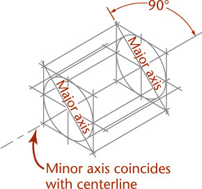
Tip
Here is a useful rule. The major axis of the ellipse is always at right angles to the centerline of the cylinder, and the minor axis is at right angles to the major axis and coincides with the centerline.
![]() Draw the two large arcs, with radius R, from the intersections of the perpendiculars in the two closest corners of the parallelogram.
Draw the two large arcs, with radius R, from the intersections of the perpendiculars in the two closest corners of the parallelogram.

![]() Draw the two small arcs, with radius r, from the intersections of the perpendiculars within the parallelogram, to complete the ellipse.
Draw the two small arcs, with radius r, from the intersections of the perpendiculars within the parallelogram, to complete the ellipse.
Tip
As a check on the accurate location of these centers, you can draw a long diagonal of the parallelogram as shown in Step 4. The midpoints of the sides of the parallelogram are points of tangency for the four arcs.
More Accurate Ellipses
The four-center ellipse deviates considerably from a true ellipse. As shown in Figure 3.50a, a four-center ellipse is somewhat shorter and “fatter” than a true ellipse. When the four-center ellipse is not accurate enough, you can use a closer approximation called the Orth four-center ellipse to produce a more accurate drawing.

Step by Step: Drawing an Orth Four-Center Ellipse
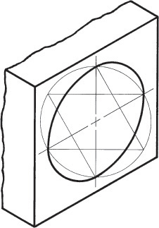
To create a more accurate approximate ellipse using the Orth method, follow the steps for these methods. The centerline method is convenient when starting from a hole or cylinder.
Centerline Method
![]() Draw the isometric centerlines. From the center, draw a construction circle equal to the actual diameter of the hole or cylinder. The circle will intersect the centerlines at four points, A, B, C, and D.
Draw the isometric centerlines. From the center, draw a construction circle equal to the actual diameter of the hole or cylinder. The circle will intersect the centerlines at four points, A, B, C, and D.

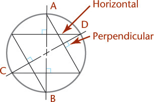
![]() From the two intersection points on one centerline, draw perpendiculars to the other centerline. Then draw perpendiculars from the two intersection points on the other centerline to the first centerline.
From the two intersection points on one centerline, draw perpendiculars to the other centerline. Then draw perpendiculars from the two intersection points on the other centerline to the first centerline.
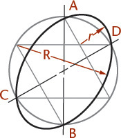
![]() With the intersections of the perpendiculars as centers, draw two small arcs and two large arcs.
With the intersections of the perpendiculars as centers, draw two small arcs and two large arcs.
Enclosing-Rectangle Method
![]() Locate center of circle and block in enclosing isometric rectangle.
Locate center of circle and block in enclosing isometric rectangle.

![]() Use the midpoint of the isometric rectangle (the distance from A to B) to locate the foci on the major axis.
Use the midpoint of the isometric rectangle (the distance from A to B) to locate the foci on the major axis.

![]() Draw lines at 60° from horizontal through the foci (points C and D) to locate the center of the large arc R.
Draw lines at 60° from horizontal through the foci (points C and D) to locate the center of the large arc R.
![]() Draw the two large arcs R tangent to the isometric rectangle. Draw two small arcs r, using foci points C and D as centers, to complete the approximate ellipse.
Draw the two large arcs R tangent to the isometric rectangle. Draw two small arcs r, using foci points C and D as centers, to complete the approximate ellipse.

Note that these steps are exactly the same as for the regular four-center ellipse, except for the use of the isometric centerlines instead of the enclosing parallelogram. (When sketching, it works fine to just draw the enclosing rectangle and sketch the arcs tangent to its sides.)
Special templates like this isometric template with angled lines and ellipses oriented in various isometric planes make it easy to draw isometric sketches. The ellipses are provided with markings to coincide with the isometric centerlines of the holes—a convenient feature in isometric drawing.
You can also draw ellipses using an ellipse template. Select the size and alignment of the major and minor axes of the ellipse to match the orientation of the shape in your drawing.
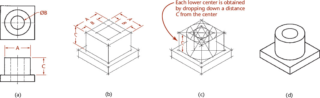
3.19 Drawing Isometric Cylinders
A typical drawing with cylindrical shapes is shown in Figure 3.51. Note that the centers of the larger ellipse cannot be used for the smaller ellipse, though the ellipses represent concentric circles. Each ellipse has its own parallelogram and its own centers. Notice that the centers of the lower large ellipse are drawn by projecting the centers of the upper large ellipse down a distance equal to the height of the cylinder.
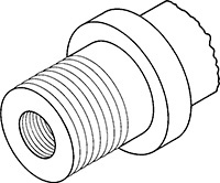
3.20 Screw Threads in Isometric
Parallel partial ellipses equally spaced at the symbolic thread pitch are used to represent only the crests of a screw thread in isometric (Figure 3.52). The ellipses may be sketched, drawn by the four-center method, or created using an ellipse template.
3.21 Arcs in Isometric
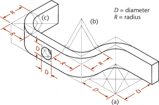
The four-center ellipse construction can be used to sketch or draw circular arcs in isometric. Figure 3.53a shows the complete construction. It is not necessary to draw the complete constructions for arcs, as shown in Figures 3.53b and c. Measure the radius R from the construction corner, then at each point, draw perpendiculars to the lines. Their intersection is the center of the arc. Note that the R distances are equal in Figures 3.53b and c, but that the actual radii used are quite different.
3.22 Spheres in Isometric
The isometric drawing of any curved surface can be constructed from all lines that can be drawn on that surface. For spheres, select the great circles (circles cut by any plane through the center) as the lines on the surface. Because all great circles, except those that are perpendicular or parallel to the plane of projection, are shown as ellipses having equal major axes, they enclose a circle whose diameter is the major axis of the ellipse.
Figure 3.54 shows two given views of a sphere enclosed in a construction cube. Next, an isometric of a great circle is drawn in a plane parallel to one face of the cube. There is no need to draw the ellipse, since only the points on the diagonal located by measurements a are needed to establish the ends of the major axis and thus to determine the radius of the sphere.
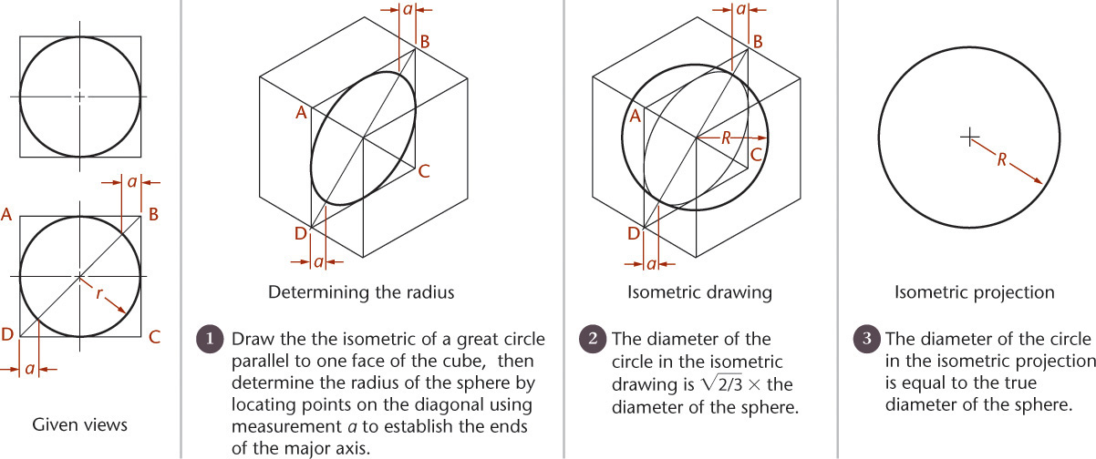
In the resulting isometric drawing, the diameter of the circle is ![]() times the actual diameter of the sphere. The isometric projection is simply a circle whose diameter is equal to the true diameter of the sphere.
times the actual diameter of the sphere. The isometric projection is simply a circle whose diameter is equal to the true diameter of the sphere.
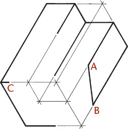
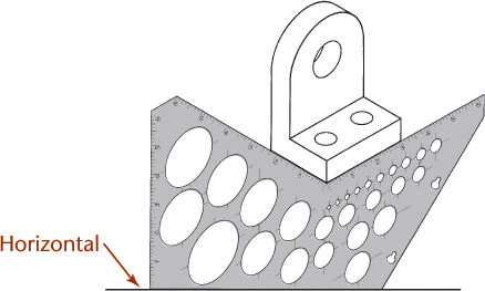
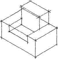
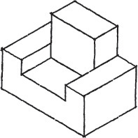
Step by Step: Isometric Sketching from an Object
Positioning the Object
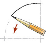
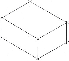
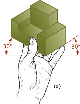
To make an isometric sketch from an actual object, first hold the object in your hand and tilt it toward you, as shown in the illustration. In this position the front corner will appear vertical. The two receding bottom edges and those edges parallel to them should appear to be at about 30° with horizontal. The steps for sketching the object follow.
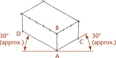
![]() Sketch the enclosing box lightly, making AB vertical and AC and AD approximately 30° with horizontal. These three lines are the isometric axes. Make AB, AC, and AD approximately proportional in length to the actual corresponding edges on the object. Sketch the remaining lines parallel to these three lines.
Sketch the enclosing box lightly, making AB vertical and AC and AD approximately 30° with horizontal. These three lines are the isometric axes. Make AB, AC, and AD approximately proportional in length to the actual corresponding edges on the object. Sketch the remaining lines parallel to these three lines.
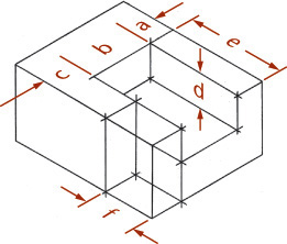
![]() Block in the recess and the projecting block.
Block in the recess and the projecting block.
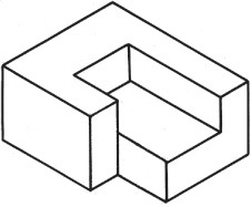
![]() Darken all final lines.
Darken all final lines.
CAD at Work: Isometric Sketches Using AutoCAD Software
Need a quick isometric sketch? AutoCAD software has special drafting settings for creating an isometric style grid.
Figure A shows the Drafting Settings dialog box in AutoCAD. When you check the button for Isometric snap, the software calculates the spacing needed for an isometric grid. You can use it to make quick pictorial sketches like the example shown in Figure B. Piping diagrams are often done this way, although they can also be created using 3D tools.
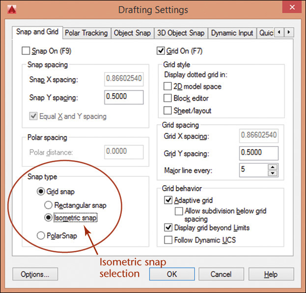
(A) Selecting Isometric Snap in the AutoCAD Drafting Settings Dialog Box (Autodesk screen shots reprinted courtesy of Autodesk, Inc.)

Even though the drawing in Figure B looks 3D, it is really drawn in a flat 2D plane. You can observe this if you change the viewpoint so you are no longer looking straight onto the view.
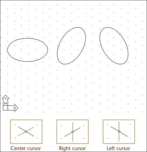
The Ellipse command in AutoCAD has a special Isocircle option that makes drawing isometric ellipses easy. The isocircles are oriented in different directions depending on the angle of the snap cursor. Figure C shows isocircles and snap cursors for the three different orientations. In the software, you press <Ctrl> and E simultaneously to toggle the cursor appearance.
3.23 Oblique Sketches
Oblique drawing is an easy method for creating quick pictorials (Figure 3.55). In most oblique sketches, circles and angles parallel to the projection plane are true size and shape and are therefore easy to construct. Although circular shapes are easy to sketch in the front oblique plane, they would appear elliptical in the top or sides. Oblique views are primarily a sketching technique used when the majority of circular shapes appear in the front view or when the object can be rotated to position circles in the front view.
CAD is not typically used to create oblique views because better-appearing isometric or perspective drawings can be created easily from 3D CAD models.
Appearance of Oblique Drawings
Three things affect the appearance of your oblique sketch:
1. The surface of the object you choose to show parallel to the projection plane
2. The angle and orientation you choose for the receding lines that depict the object’s depth
3. The scale you choose for the receding lines depicting the object’s depth (Figure 3.56)

Meat Cereals. Oblique sketching shows the front surface parallel to the view, making these meat cereal boxes easy to draw. (Courtesy of Randall Munroe.)
Choosing the Front Surface
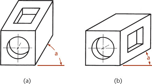
Think about which surface of the object would be the best one to think of as parallel to the plane of projection. For example, a cube has six different surfaces. As you are creating your sketch, any of those six surfaces could be oriented as the “front” of the part. Of course, with a cube it wouldn’t matter which one you chose. But a cube with a hole through it will make a much better oblique sketch when the round hole is oriented parallel to the projection plane.
Angle of Receding Lines
An angle of 45° is often chosen for the angle of the receding lines because it makes oblique sketches quick and easy. You can use graph paper and draw the angled lines through the diagonals of the grid boxes. An angle of 30° is also a popular choice. It can look more realistic at times. Any angle can be used, but 45° is typical. As shown in Figure 3.57, you can produce different oblique drawings by choosing different directions for the receding lines.
3.24 Length of Receding Lines
Theoretically, oblique projectors can be at any angle to the plane of projection other than perpendicular or parallel. The difference in the angle you choose causes receding lines of oblique drawings to vary in angle and in length from near zero to near infinity. However, many of those choices would not produce very useful drawings. Figure 3.58 shows a variety of oblique drawings with different lengths for the receding lines.

Because we see objects in perspective (where receding parallel lines appear to converge) oblique projections look unnatural to us. The longer the object in the receding direction, the more unnatural the object appears. For example, the object shown in Figure 3.58a is an isometric drawing of a cube in which the receding lines are shown full length. They appear to be too long and they appear to widen toward the rear of the block. Figure 3.59b shows how unnatural the familiar pictorial image of railroad tracks leading off into the distance would look if drawn in an oblique projection. To give a more natural appearance, show long objects with the long axis parallel to the view, as shown in Figure 3.60.


Cavalier Projection
When the receding lines are true length—(the projectors make an angle of 45° with the plane of projection)—the oblique drawing is called a cavalier projection (Figure 3.58a). Cavalier projections originated in the drawing of medieval fortifications and were made on horizontal planes of projection. On these fortifications the central portion was higher than the rest, so it was called cavalier because of its dominating and commanding position.
Cabinet Projection
When the receding lines are drawn to half size (Figure 3.58d), the drawing is known as a cabinet projection. This term is attributed to the early use of this type of oblique drawing in the furniture industries. Figure 3.61 shows a file drawer drawn in cavalier and cabinet projections.
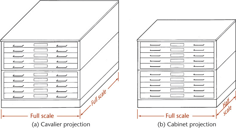
3.25 Choice of Position in Oblique Drawings
Orient the view so that important shapes are parallel to the viewing plane, as shown in Figure 3.62. In Figures 3.62a and c, the circles and circular arcs are shown in their true shapes and are easy to draw. In Figures 3.62b and d they are not shown in true shape and must be plotted as free curves or ellipses.
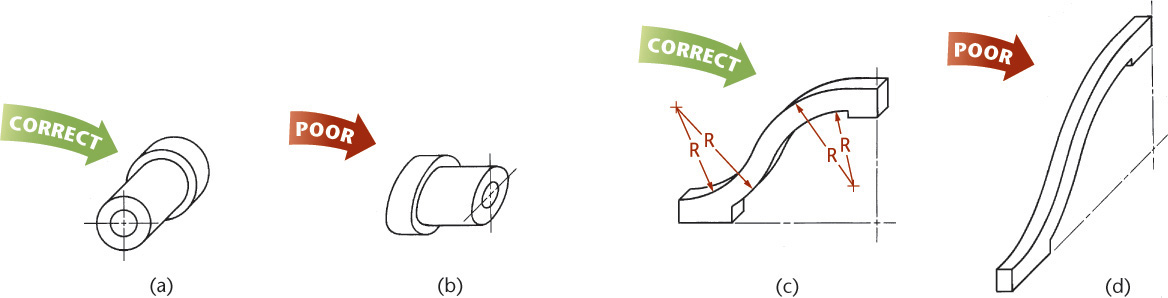
3.26 Ellipses for Oblique Drawings
Circular shapes that are parallel to the front plane of projection appear as circles in oblique view. In isometric views they appear elliptical. Figure 3.63 shows a comparison of a cylinder drawn in isometric and oblique views.
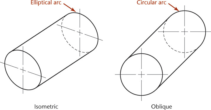
It is not always possible to orient the view of an object so that all its rounded shapes are parallel to the plane of projection. For example, the object shown in Figure 3.64a has two sets of circular contours in different planes. Both cannot be simultaneously placed parallel to the plane of projection, so in the oblique projection, one of them must be viewed as an ellipse.
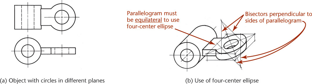
If you are sketching, you can just block in the enclosing rectangle and sketch the ellipse tangent to its sides. Using CAD, you can draw the ellipse by specifying its center and major and minor axes. In circumstances where a CAD system is not available, if you need an accurate ellipse, you can draw it by hand using a four-center arc approximation.
3.27 Angles in Oblique Projection
When an angle that is specified in degrees lies in a receding plane, convert the angle into linear measurements to draw the angle in an oblique drawing. Figure 3.65a shows a drawing with an angle of 30° specified.
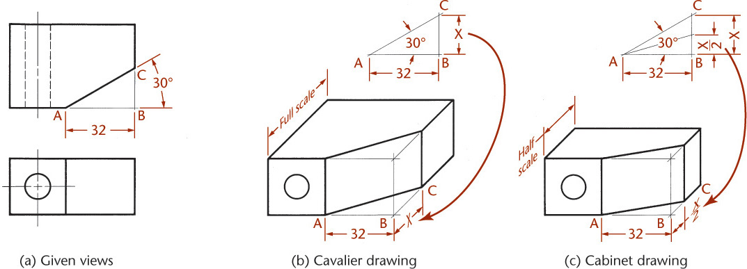
To draw the angle in the oblique drawing, you will need to know distance X. The distance from point A to point B is given as 32 mm. This can be measured directly in the cavalier drawing (Figure 3.65b). Find distance X by drawing the right triangle ABC (Figure 3.65c) using the dimensions given, which is quick and easy using CAD.
You can also use a mathematical solution to find the length of the side: The length of the opposite side equals the tangent of the angle times the length of the adjacent side. In this case, the length of the opposite side, X, is about 18.5 mm. Draw the angle in the cavalier drawing using the found distance.
Remember that all receding dimensions must be reduced to match the scale of the receding axis. In the cabinet drawing in Figure 3.65c, the distance BC must be half the side BC of the right triangle in Figure 3.65c.
Step by Step: Using Box Construction to Create an Oblique Drawing
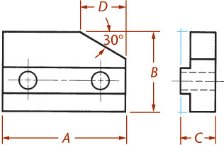
Follow these steps to draw a cavalier drawing of the rectangular object shown in the two orthographic views.
![]() Lightly block in the overall width (A) and height (B) to form the enclosing rectangle for the front surface. Select an angle for the receding axis (OZ) and draw the depth (C) along it.
Lightly block in the overall width (A) and height (B) to form the enclosing rectangle for the front surface. Select an angle for the receding axis (OZ) and draw the depth (C) along it.
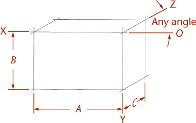
![]() Lightly block in the details of the front surface shape including the two holes, which will appear round. Add the details of the right-side surface shape. Extend lines along the receding axis connecting the edges to form the remaining surface edges.
Lightly block in the details of the front surface shape including the two holes, which will appear round. Add the details of the right-side surface shape. Extend lines along the receding axis connecting the edges to form the remaining surface edges.

![]() Darken the final lines.
Darken the final lines.
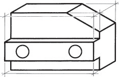
Step by Step: Using Skeleton Construction in Oblique Drawing
Oblique drawings are especially useful for showing objects that have cylindrical shapes built on axes or centerlines. Follow these steps to construct an oblique drawing of the part shown using projected centerlines.
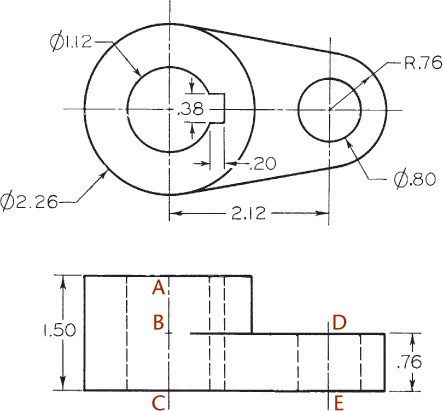
![]() Position the object in the drawing so that the circles shown in the given top view are parallel to the plane of projection. The circles will show true shape in the oblique view. Draw the circular shape in the front plane of the oblique view and extend the center axis along the receding axis of the oblique drawing.
Position the object in the drawing so that the circles shown in the given top view are parallel to the plane of projection. The circles will show true shape in the oblique view. Draw the circular shape in the front plane of the oblique view and extend the center axis along the receding axis of the oblique drawing.
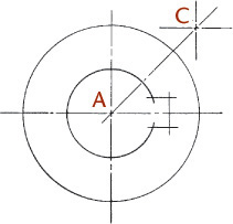
![]() Add the centerline skeleton as shown.
Add the centerline skeleton as shown.
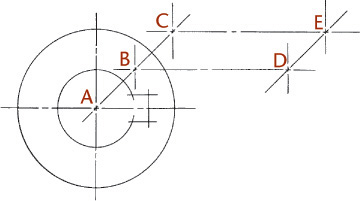
![]() Build the drawing from the location of these centerlines.
Build the drawing from the location of these centerlines.

![]() Construct all important points of tangency.
Construct all important points of tangency.

![]() Darken the final cavalier drawing.
Darken the final cavalier drawing.
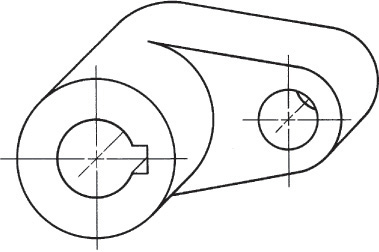
3.28 Sketching Assemblies
Assembly drawings are used to show how parts fit together. Because they do not need to provide all the information to make individual parts, isometric sketches or drawings are often used that show only the exterior view of the assembled parts. You can use assembly sketches as you design to identify areas that must fit together or have common dimensions, or to maintain critical distances to ensure that the device will function as expected. Figure 3.66 shows an isometric sketch of an assembly.
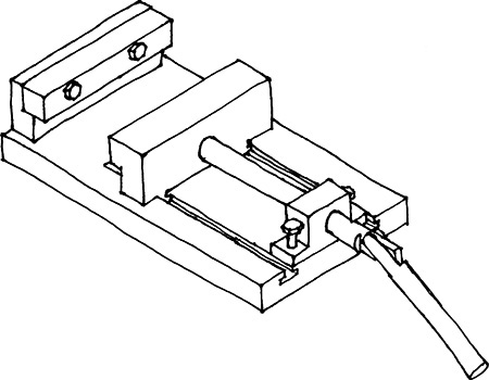
Sketched assembly drawings are useful in documenting your ideas in a rougher state. An exploded isometric assembly drawing shows the individual parts moved apart from one another along the isometric axis line directions. A centerline pattern is used to show how the parts relate and fit together.
When creating an exploded assembly sketch, keep the parts lined up with the other parts where they assemble. If possible, move any single parts along only one axis direction. In Figure 3.67, all exploded parts are moved along only one axis direction. Notice the centerline pattern showing how the parts align. If you must move a part in two different directions so that it can be seen clearly, add a centerline showing how the part must move to get to its proper location in the assembly. In Figure 3.68, parts have been moved in two axis directions. You can see the jog in the centerline indicating how the part has been moved.
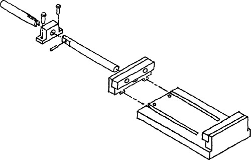
3.67 Exploded Isometric Assembly Sketch. Centerlines have been added to show where parts line up in the assembly.
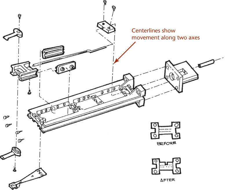
3.68 Isometric Assembly Sketch. Some parts have been exploded in two directions so they do not overlap other parts in the assembly. The centerlines indicate the path the part must follow to assemble correctly. (Courtesy of Albert W. Brown, Jr.)
Finished assembly drawings that will be given to manufacturing workers to show them how to produce a device also contain a parts list that identifies each part in the assembly, the quantity necessary, the material of each part, and a number identifying which item it is on the drawing. A parts list can also be included on a sketched assembly drawing. Sometimes it is helpful to give a quick assembly sketch to manufacturing along with part drawings, especially if they are parts you need to have manufactured quickly from a sketch. Seeing how the parts fit together in assembly will help the manufacturer understand the entire device and identify potential problems.
3.29 Sketching Perspectives
Perspective pictorials most closely approximate the view produced by the human eye. Perspective views are the type of drawing most like a photograph. Examples of a perspective drawing can be seen in Figures 3.69, 3.70a, and 3.72. Although complex perspective views are time consuming to sketch, they are easy to create from 3D CAD models.
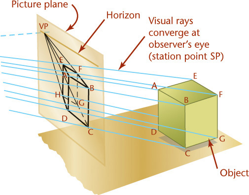

Unlike parallel types of projection, perspective projectors converge. The point at which the projectors converge is called the vanishing point. This is clearly seen in Figure 3.70a.
The first rule of perspective is that all parallel lines that are not parallel to the picture plane vanish at a single vanishing point, and if these lines are parallel to the ground, the vanishing point will be on the horizon. Parallel lines that are also parallel to the picture plane remain parallel and do not converge toward a vanishing point (Figures 3.71 and 3.72).
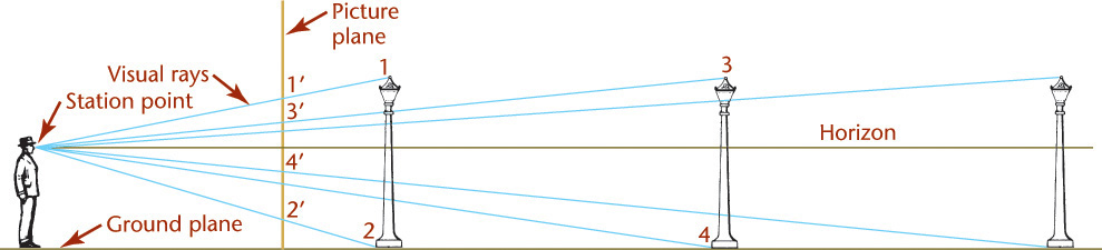
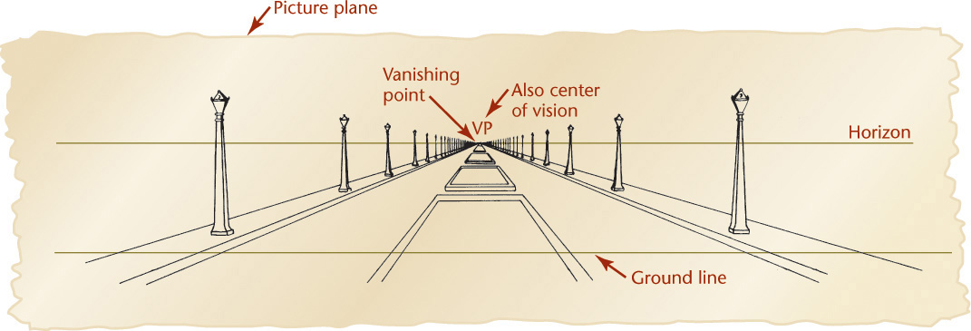
When the vanishing point is placed above the view of the object in the picture plane, the result is a bird’s-eye view, looking down onto the object. When the vanishing point is placed below the view of the object, the result is a worm’s-eye view looking up at the object from below (see Figure 3.74 on page 107).
There are three types of perspective: one-point, two-point, and three-point perspective, depending on the number of vanishing points used.
The Three Types of Perspective
Perspective drawings are classified according to the number of vanishing points required, which in turn depends on the position of the object with respect to the picture plane.
If the object sits with one face parallel to the plane of projection, only one vanishing point is required. The result is a one-point perspective, or parallel perspective.
If the object sits at an angle with the picture plane but with vertical edges parallel to the picture plane, two vanishing points are required, and the result is a two-point perspective, or an angular perspective. This is the most common type of perspective drawing.
If the object sits so that no system of parallel edges is parallel to the picture plane, three vanishing points are necessary, and the result is a three-point perspective.
One-Point Perspective
To sketch a one-point perspective view, orient the object so that a principal face is parallel to the picture plane. If desired, this face can be placed in the picture plane. The other principal face is perpendicular to the picture plane, and its lines will converge toward a single vanishing point.
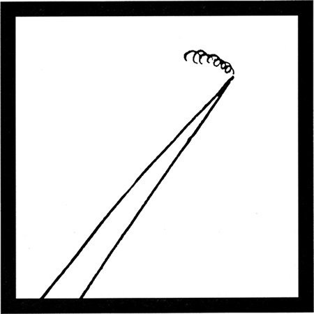
8:12 Train as Seen by 8:12 1/2 Commuter (Excerpted from Droodles – The Classic Collection by Roger Price ©2000 by Tallfellow Press. Used by permission. All rights reserved.)
Step by Step: One-Point Perspective
To sketch the bearing in one-point perspective—that is, with one vanishing point—follow the steps illustrated below.
![]() Sketch the true front face of the object, just as in oblique sketching. Select the vanishing point for the receding lines. In many cases it is desirable to place the vanishing point above and to the right of the picture, as shown, although it can be placed anywhere in the sketch. However, if the vanishing point is placed too close to the center, the lines will converge too sharply and the picture will be distorted.
Sketch the true front face of the object, just as in oblique sketching. Select the vanishing point for the receding lines. In many cases it is desirable to place the vanishing point above and to the right of the picture, as shown, although it can be placed anywhere in the sketch. However, if the vanishing point is placed too close to the center, the lines will converge too sharply and the picture will be distorted.
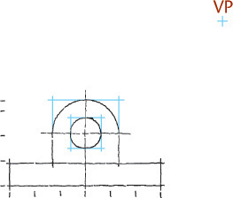
![]() Sketch the receding lines toward the vanishing point.
Sketch the receding lines toward the vanishing point.

![]() Estimate the depth to look good and sketch in the back portion of the object. Note that the back circle and arc will be slightly smaller than the front circle and arc.
Estimate the depth to look good and sketch in the back portion of the object. Note that the back circle and arc will be slightly smaller than the front circle and arc.
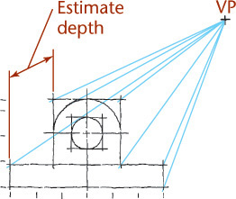
![]() Darken all final lines. Note the similarity between the perspective sketch and the oblique sketch earlier in the chapter.
Darken all final lines. Note the similarity between the perspective sketch and the oblique sketch earlier in the chapter.
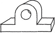
Two-Point Perspective
Two-point perspective is more true to life than one-point perspective. To sketch a two-point perspective, orient the object so that principal edges are vertical and therefore have no vanishing point; edges in the other two directions have vanishing points. Two-point perspective is especially good for representing buildings and large civil structures, such as dams or bridges.
Step by Step: Two-Point Perspective
To sketch a desk using two vanishing points, follow these steps.
![]() Sketch the front corner of the desk at true height. Locate two vanishing points (VPL and VPR) on a horizon line (at eye level). Distance CA may vary—the greater it is, the higher the eye level will be and the more we will be looking down on top of the object. A rule of thumb is to make C–VPL one third to one fourth of C–VPR.
Sketch the front corner of the desk at true height. Locate two vanishing points (VPL and VPR) on a horizon line (at eye level). Distance CA may vary—the greater it is, the higher the eye level will be and the more we will be looking down on top of the object. A rule of thumb is to make C–VPL one third to one fourth of C–VPR.
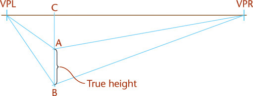
![]() Estimate depth and width, and sketch the enclosing box.
Estimate depth and width, and sketch the enclosing box.
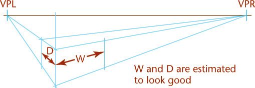
![]() Block in all details. Note that all parallel lines converge toward the same vanishing point.
Block in all details. Note that all parallel lines converge toward the same vanishing point.

![]() Darken all final lines. Make the outlines thicker and the inside lines thinner, especially where they are close together.
Darken all final lines. Make the outlines thicker and the inside lines thinner, especially where they are close together.
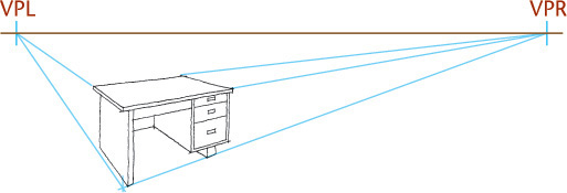
Three-Point Perspective
In three-point perspective, the object is placed so that none of its principal edges is parallel to the picture plane. Each of the three sets of parallel edges has a separate vanishing point. See Figure 3.73.
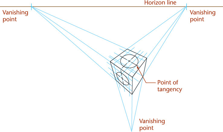
Bird’s-Eye View versus Worm’s-Eye View
The appearance of a perspective sketch depends on your view-point in relation to the object. Select some reachable object in the room and move so that you are looking at it from above and really notice its shape. Now gradually move so that you are looking at it from below. Notice how the change of viewpoint changes the appearance of its surfaces—which ones are visible and their relative size.
The horizon line in a perspective sketch is a horizontal line that represents the eye level of the observer. Locating the sketched object below the horizon line produces a view from above (or a bird’s-eye view). Locating the sketched object above the horizon line produces a view from below (or a worm’s-eye view). Figure 3.74 illustrates the horizon line in a drawing and the effect of placing the object above or below the horizon line.
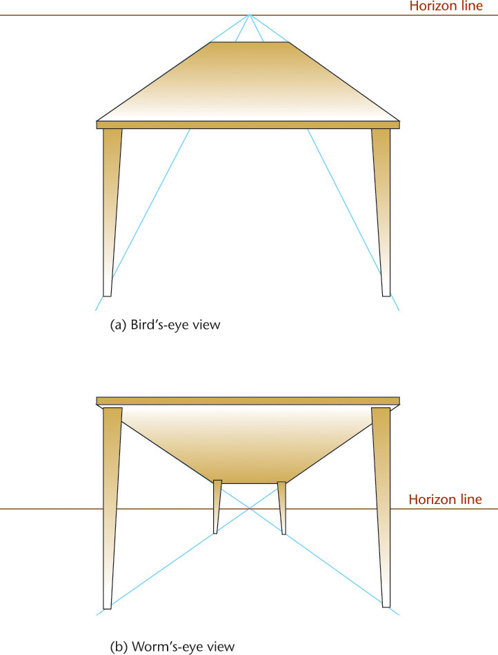
3.30 Curves and Circles in Perspective
If a circle is parallel to the picture plane, its perspective view is a circle. If the circle is inclined to the picture plane, its perspective drawing may be any one of the conic sections in which the base of the cone is the given circle, the vertex is the station point, and the cutting plane is the picture plane (see Figure 3.71). The centerline of the cone of rays is usually approximately perpendicular to the picture plane, so the perspective will usually be an ellipse.
An ellipse may be drawn using a method of blocking in its center and a box tangent to the ellipse as shown in Figure 3.75. Also shown is a convenient method for determining the perspective of any planar curve.

3.31 Shading
Shading can make it easier to visualize pictorial drawings, such as display drawings, patent drawings, and catalog drawings. Ordinary multiview and assembly drawings are not shaded. The shading should be simple, reproduce well, and produce a clear picture. Some of the common types of shading are shown in Figure 3.76. Two methods of shading fillets and rounds are shown in Figures 3.76c and d. Shading produced with dots is shown in Figure 3.76e, and pencil tone shading is shown in Figure 3.76f. Pencil tone shading used in pictorial drawings on tracing paper reproduces well only when making blueprints, not when using a copier.

3.32 Computer Graphics
Pictorial drawings of all types can be created using 3D CAD (Figures 3.77 and 3.78). To create pictorials using 2D CAD, use projection techniques similar to those presented in this chapter. The advantage of 3D CAD is that once you make a 3D model of a part or assembly, you can change the viewing direction at any time for orthographic, isometric, or perspective views. You can also apply different materials to the drawing objects and shade them to produce a high degree of realism in the pictorial view.

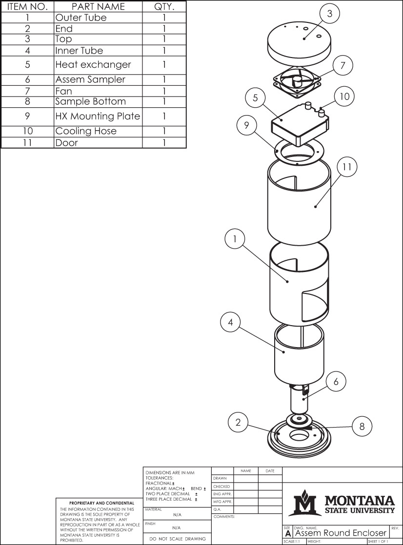
3.33 Drawing on Drawing
Because CAD helps people produce accurate drawings that are easy to alter, store, and repurpose, computer automation has made the painstaking aspects of hand-rendering technical drawings nearly obsolete. Still, the ability to sketch with clarity is an immediate and universal way to record and communicate ideas.
The ability to think of complex objects in terms of their basic solid components and to identify relationships between various surfaces, edges, and vertices is basic to creating both hand-drawn (Figure 3.79) and computer-generated technical drawings. By understanding how to represent objects accurately, you can communicate efficiently as part of a team and increase your constructive visualization ability, or your ability to “think around corners.”
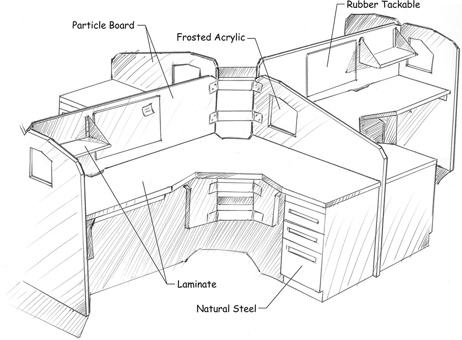
3.79 Hand Sketch Conveying Custom Workstation Furniture Concept (Courtesy of Jacob A. Baron-Taltre.)
CAD at Work: Sketching and Parametric Modeling
The Design Process
The parametric modeling process in many ways mirrors the design process. Parametric CAD software lets you specify geometry, dimensions, and other essential parameters that control the model. To get the rough ideas down, the designer starts by making hand sketches. Then as the ideas are refined, more accurate drawings are created either with instruments or using CAD. Necessary analysis is performed and, in response, the design may change. The drawings are revised as needed to meet the new requirements. Eventually the drawings are approved so that the parts may be manufactured.
Rough Sketches
Using parametric modeling software, the designer first roughly sketches the basic shapes on the computer screen as though sketching freehand. These sketches do not need to have perfectly straight lines or accurate corners. The software interprets the sketch much as you would interpret a rough sketch given to you by a colleague. If the lines are nearly horizontal or vertical, the software assumes that you meant them to be so. If the line appears to be perpendicular, the software assumes that it is.
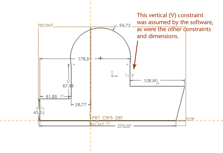
A Rough Sketch in Pro/ENGINEER Sketcher
Constraining the Sketch
Using a parametric CAD system, you next refine the two-dimensional sketch by adding geometric constraints, which tell how to interpret the sketch, and by adding parametric dimensions, which control the size of sketch geometry. Once the sketch is refined, you can create it as a 3D feature to which other features can be added. As the design changes, you can change the dimensions and constraints that control the sketch geometry, and the parametric model will be updated to reflect the new design.
When you are creating sketches by hand or for parametric modeling, think about the implications of the geometry you are drawing. Does the sketch imply that lines are perpendicular? Are the arcs that you have drawn intended to be tangent or intersecting? When you create a parametric model, the software applies rules to constrain the geometry, based on your sketch. You can remove, change, or add new constraints, but to use the software effectively you need to accurately depict the geometry you want formed.
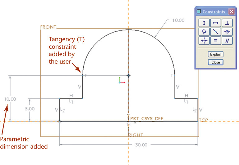
A Constrained Sketch
CAD at Work: Perspective Views in AutoCAD
AutoCAD software provides options for parallel and perspective viewing. You can use the menu for the ViewCube to quickly select Parallel or Perspective viewing options (Figure A). The defaults for perspective viewing determine the basic appearance when you select the perpective view types. Notice that the grid squares in the figure appear larger closer to the view and smaller when they are farther away. When parallel projection is selected, the grid lines remain parallel.
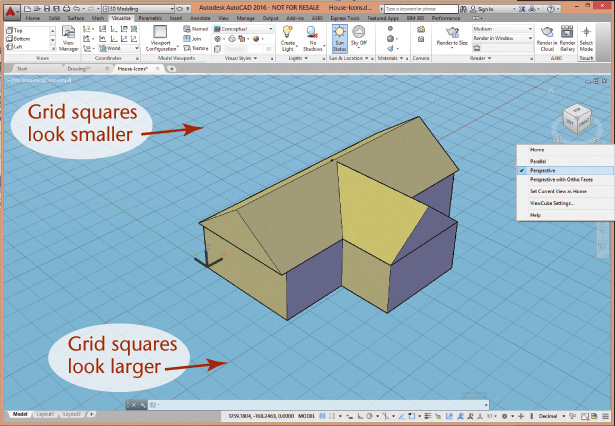
(A) A Perspective View Created Using the DView Command in AutoCAD (Autodesk screen shots reprinted courtesy of Autodesk, Inc.)
An interactive command, Dview (dynamic viewing), lets you show 3D models and drawings in perspective (or parallel view) and interactively change the viewing options. Dview uses a camera and target analogy to create perspective views. Using the Camera option, you select a camera position (similar to the station point) with respect to the target point at which the camera is aimed. The Dview Distance option lets you change the distance between the camera and the object and calculate a new view. The Off option of the command turns perspective viewing off to return to a parallel view.
Specifying a distance that is too close can fill up the entire view with the object, in the same way that a close-up shot with a camera does.
The Zoom option of the Dview command acts like a normal zoom command when perspective viewing is off. When perspective viewing is on, you can zoom dynamically by moving the slider bar shown in Figure B to adjust the camera lens to change the field of view. The default is to show the view similar to what you would see through a camera with a 50 mm lens. During the Zoom option, moving the slider is similar to choosing the focal length for a camera lens, which changes the relative perspective appearance (Figure B). Shorter focal lengths exaggerate the perspective effect of closer features.
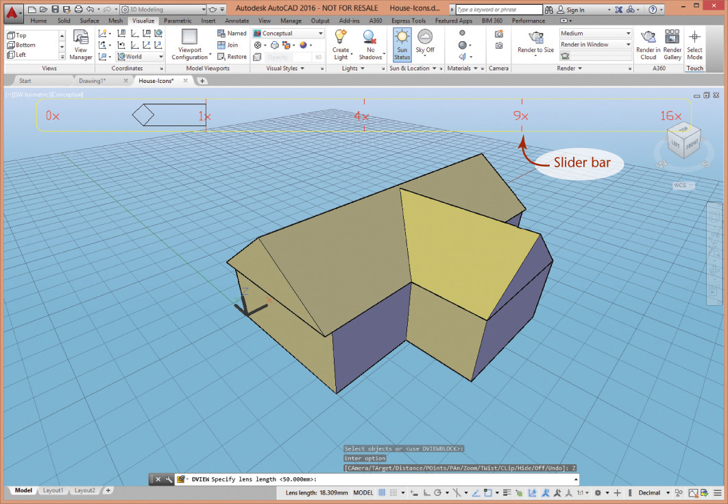
(B) Using the Zoom Slider to Adjust Field of View (Autodesk screen shots reprinted courtesy of Autodesk, Inc.)
Industry Case: Sketching for Ideation: A CrossAction Breakthrough
When Oral-B hired LUNAR to create an innovative approach to brushing (and a new flagship product), they had no preconceived notions of what that would mean. But they knew that they wanted a brush that was ergonomically superior to the traditional “flat stick” design, and they wanted the brush to improve brushing effectiveness. The development of the Oral-B CrossAction Toothbrush is an example of the power of ideation in product design.
Jeff Salazar, lead designer for the project, started first not with sketches but with extensive research into the kinesiology of brushing teeth. A research firm had been hired to do a study of how people hold their toothbrushes as they brush. They found that there are five basic grips. Each person might use more than one depending on the part of the mouth to be brushed. Two or three grips were the ones used by most people.
As the kinesiology study was underway the design team at LUNAR undertook their own study of brushing. Given that the design constraints were focused almost totally on ergonomics, they studied how people brush. They engaged team members and others and watched them brush. They used models of teeth to investigate brushing. They bought “flat stick” toothbrushes, heated them so they could be bent at different angles, and had a variety of people report back on their brushing experience with handles of different shapes. People of various sizes and backgrounds, male and female, were asked to brush with the angled handles. This helped them understand the extremes of the angles forward and back that the handle could form.

They also studied the competition. A competitor had come out with what it promised was a superior toothbrush—one that was “bent like a dental instrument.” After trying the toothbrush, however, the team concluded that the shape was only superior if someone else (e.g., the dental hygienist) was brushing your teeth. This key insight helped them focus the next stage of ideation on shapes with potential.
After discussing their results, the team selected five to six angle configurations for further study. The ergonomic results of the team’s efforts were an instinct that people wanted a toothbrush that would “fill the hand” more than the thin stick. But where should the brush be thicker? The team created a matrix that paired each of the angle configurations with the range of options for the handles’ thickness (Figure 3.80). Then, Jeff began sketching all the various combinations (see Figure 3.81).
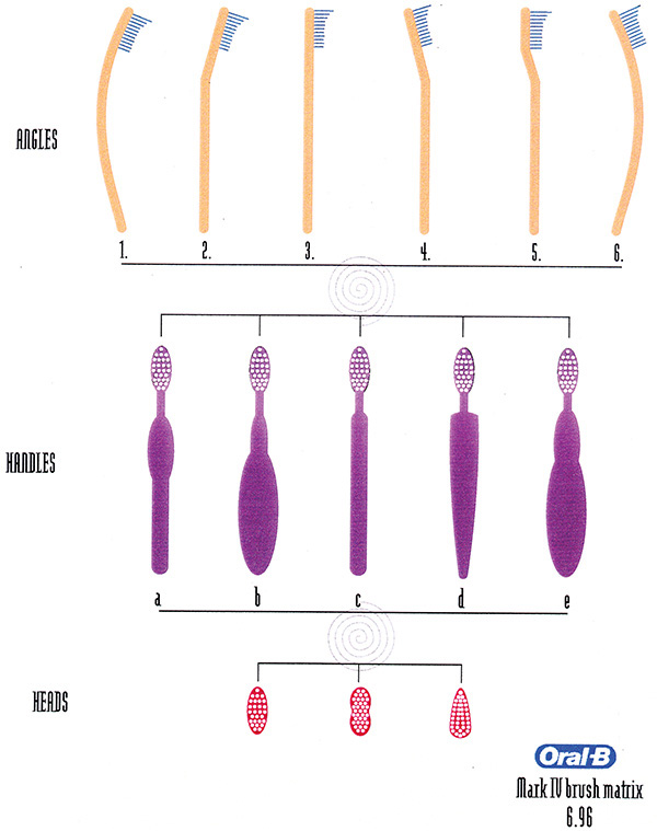

After about a week of generating pencil sketches, Jeff decided he needed to “sketch” in 3D. Starting with a full-size sketch (Figure 3.82), he used a band saw to cut the shape of the sketch in foam, then shaped the foam into a model that he and others could hold and evaluate for various grips (Figure 3.83). Those that didn’t work for one grip or another were eliminated. The LUNAR team and their counterparts at Oral-B reviewed the various options and selected four for further development.
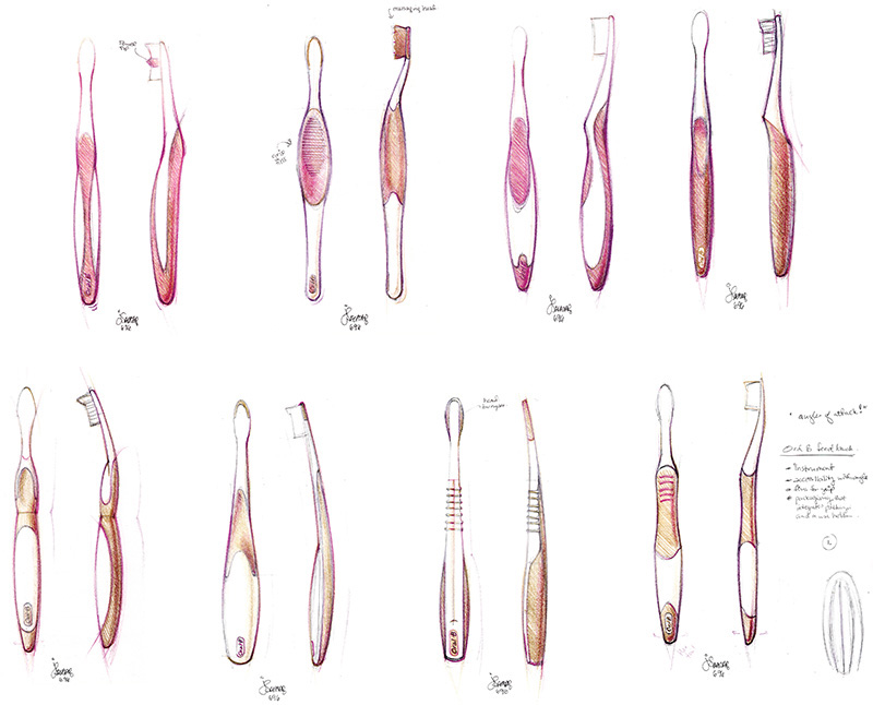
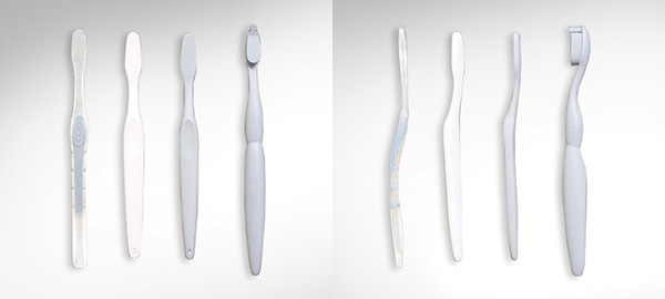
At this point, the team created 3D models of the four candidates. Oral-B had prototypes made from the CAD models for the handles (Figure 3.84), added bristles, and embarked on consumer research that would drive the next stage of refinement. Consumers were asked to brush for one month, then attend a focus group to report on their experience. LUNAR Design was present to hear consumer reactions.

What they found was that consumers loved the fatter handle. Its shape in the hand gave them more control when moving the brush to different parts of their mouth. The form provided optimal ergonomics for each of the five common grips. The faceted surface on the handle gave users a tactile clue as to where to place their fingers when gripping. The rubber like material used for the facets was located where users exerted the most finger pressure—and it made it easier to hold the brush when wet. The very positive response indicated that the ergonomic handle could make a significant difference in brushing that consumers would appreciate. People reported that they loved their toothbrush now!
At the same time, Jeff and the LUNAR and Oral-B teams had to listen and interpret what they heard. Focus groups are a wealth of different reactions, and it is up to the team to determine what is relevant and what is peripheral. For example, one reaction was that the fatter handle did not fit in the standard toothbrush holder. The team had to assess whether this was an issue that would hamper acceptance of the toothbrush or whether the improved brushing experience would outweigh its importance to the customer.
The refinement of the design proceeded through two more prototypes (and additional ideation around packaging; see Figure 3.85) before the final Oral-B CrossAction was launched. The intensity of the ideation stage—and the many techniques used to generate and evaluate design ideas—were critical to the team’s success in achieving this breakthrough in brushing.
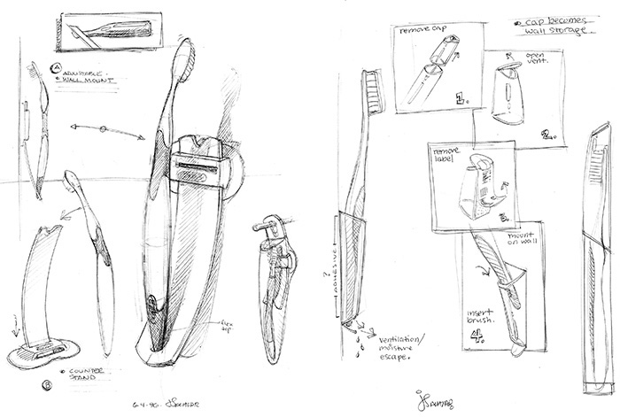
(All images courtesy of LUNAR.)
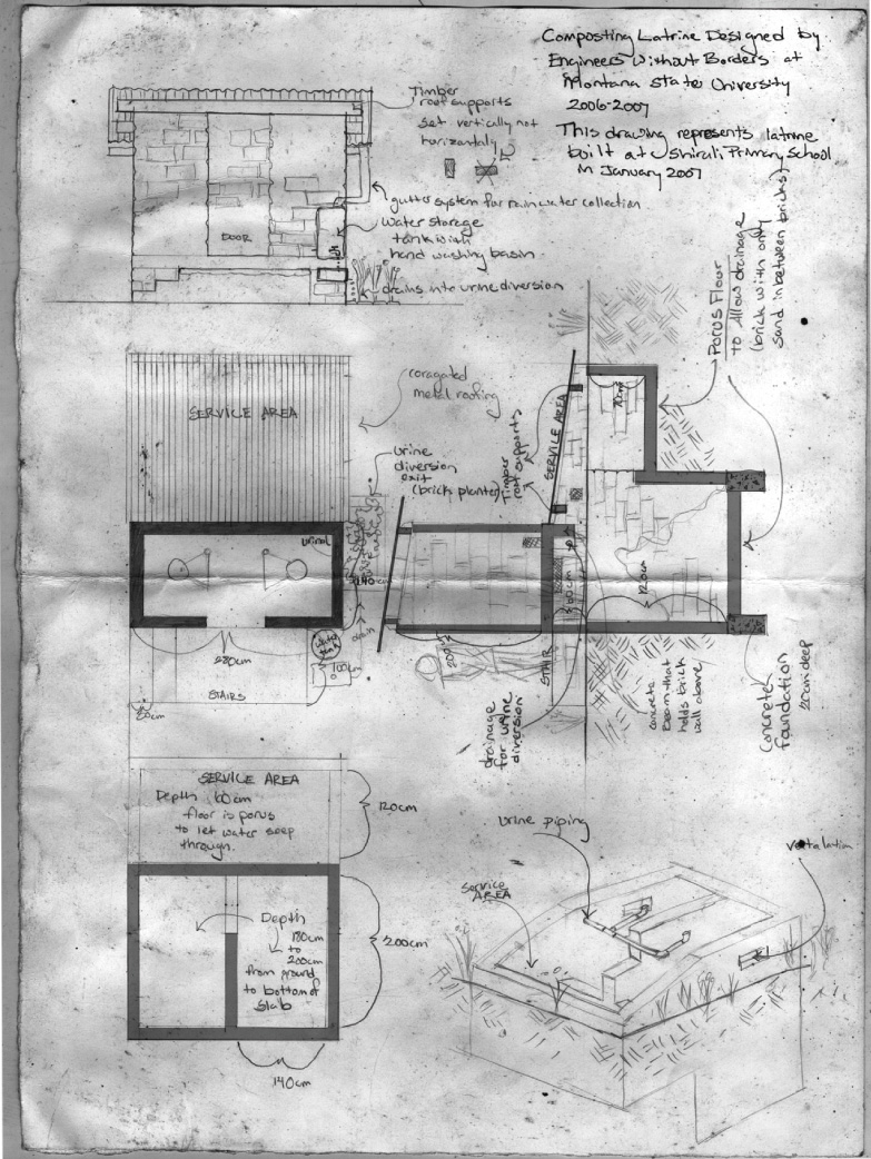
Sketch for a Composting Latrine. The student chapter of Engineers Without Borders at Montana State University is collaborating with 57 schools in the Khwisero Division of southwestern Kenya to provide sustainable sanitary improvements including wells and composting latrines. (Sketch courtesy of Andrea Orr, Engineers Without Borders, MSU.)
Andrea Orr was a student in environment design at Montana State University and a co-fundraiser and co-project designer in the MSU chapter of Engineers Without Borders.
She created the sketch above during the building of a composting latrine that she and Chris Allen designed for a school in the Khwisero Division of southwestern Kenya. The sketch showed instructors and local government officials how the latrine would work.
Though they had done multiple sketches ahead of time, she and Allen did this sketch to clarify their ideas into one concept.
Orr did the sketch outdoors, sitting next to the school building. There was no computer available, because at the remote location, electricity was rarely available. She also did a drawing explaining how to use and maintain the latrine, which was posted inside the finished structure.
Orr said that when she is not working in the field, she still sketches by hand before transferring to CAD.
“There’s little bit of vagueness in a hand-drawn sketch that keeps it open to creativity,” said Orr.
“If you show a sketch to someone they are more likely to offer input and ideas than if it looks like a finished CAD rendering. That’s one of the reasons I don’t work in CAD until quite a few revisions into the project.”
Chapter Summary
• Sketching is a quick way of visualizing and solving a drawing problem. It is an effective way of communicating with all members of the design team.
• Three-dimensional figures are bounded by surfaces that are either planar, single-curved, double-curved, or warped.
• Prisms, pyramids, cylinders, cones, tori, and ellipsoids are common shapes in engineering drawings. There are also five regular polyhedra: the tetrahedron, hexahedron, octahedron, dodecahedron, and icosahedron.
• There are special techniques for sketching lines, circles, and arcs. These techniques should be practiced so they become second nature.
• Using a grid makes sketching in proportion an easy task.
• Circles can be sketched by constructing a square and locating the four tangent points where the circle touches the square.
• A sketched line does not need to look like a CAD or mechanical line. The main distinction between CAD and instrumental drawing and freehand sketching is the character or technique of the line work.
• Freehand sketches are made to proportion, but not necessarily to a particular scale.
• Sketching is one of the most important skills for accurately recording ideas.
• Isometric, oblique, and perspective are three methods used to create pictorial sketches.
Review Questions
1. What are the advantages of using grid paper for sketching?
2. What is the correct technique for sketching a circle or arc?
3. Sketch the alphabet of lines. Which lines are thick? Which are thin? Which are very light and will not reproduce when copied?
4. What type of pictorial drawing can easily be drawn on square grid paper?
5. What is the advantage of sketching an object first before drawing it using CAD?
6. What is the difference between proportion and scale?
Sketching Exercises
Exercise 3.1 Sketch the objects shown using isometric, oblique, and one- or two-point perspective.
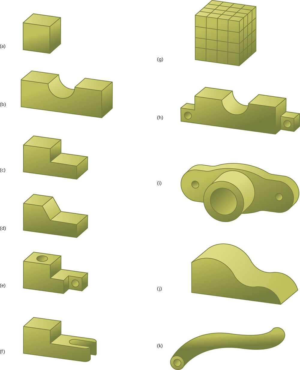
1. Practice the sketching skills and techniques you have learned for construction lines and ellipses. Set a timer for 10 minutes and make quick sketches of these nine different containers.
2. Select one container and create isometric, oblique, and perspective drawings.
3. Design a new piece of drinkware, using your sketching skills.
4. Select one container. Draw an enclosing box and shade in the negative space so that the contour of the container remains white.
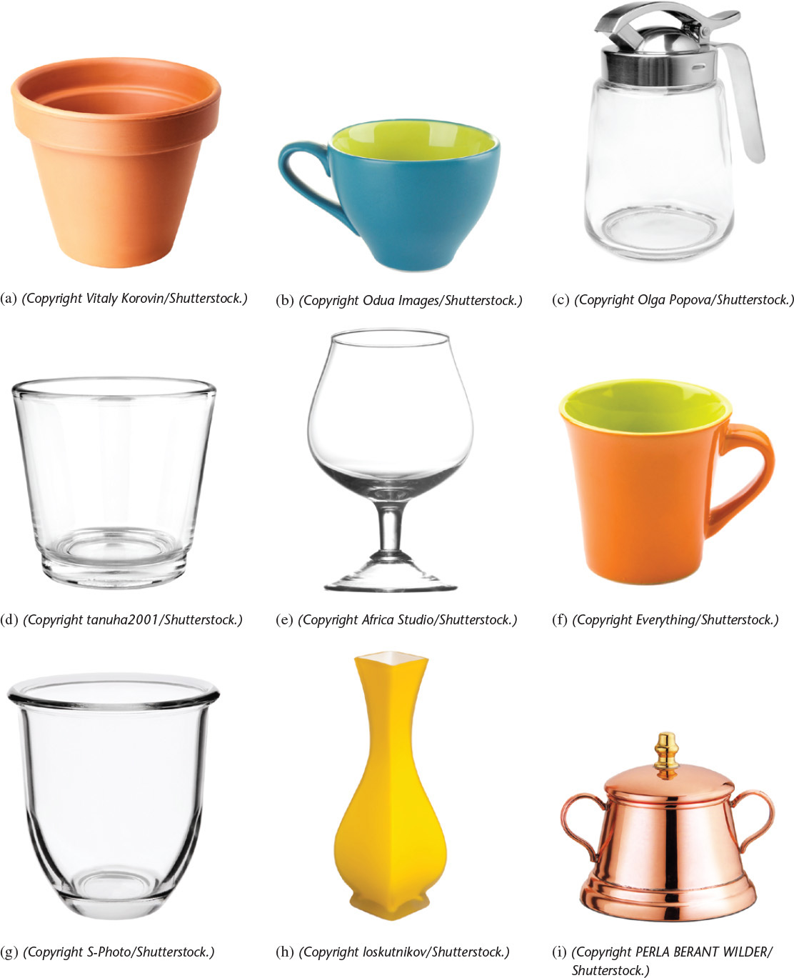
Exercise 3.3 Quick Sketch. Practice the sketching skills and techniques you have learned for construction lines and ellipses. Set a timer for 10 minutes and make quick sketches of these six different chairs.
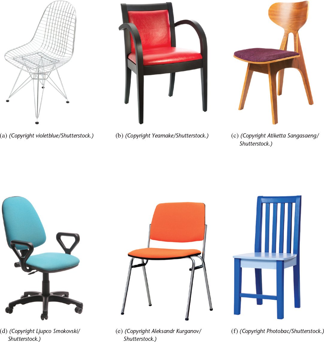
Exercise 3.4 Quick Sketch. Practice the sketching skills and techniques you have learned for construction lines and ellipses. Set a timer for 10 minutes and make quick sketches of these tools.
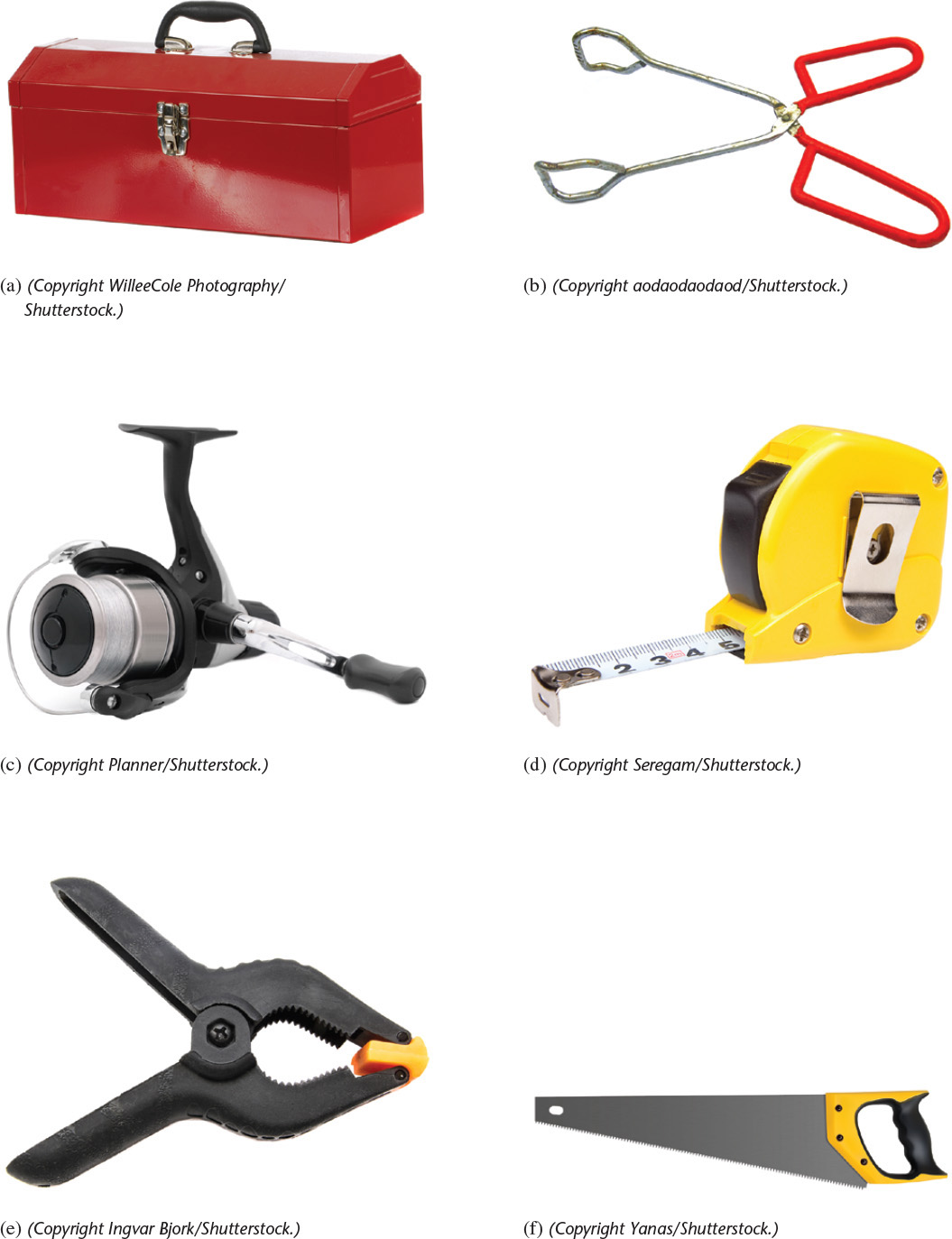
Exercise 3.5 Sketching. Practice the sketching skills and techniques you have learned for construction lines and ellipses. Set a timer for 10 minutes and make quick sketches of these items.
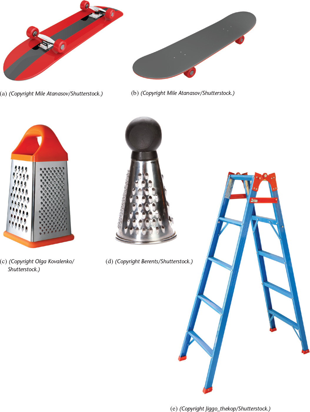

Exercise 3.6 Parking Meter. Create an oblique pictorial sketch of the parking meter shown here. Use construction lines to keep the features in proportion.
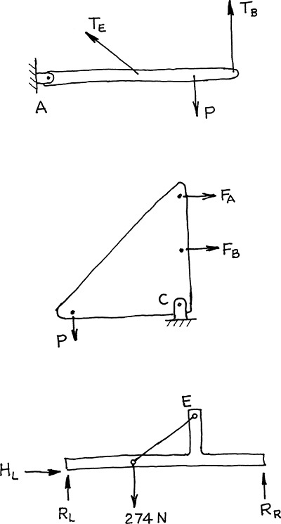
Exercise 3.7 Free-Body-Diagram Sketches. Sketch the free body diagrams as shown.

Exercise 3.8 Rocker Arm. Create a freehand sketch. Use the dimensions to help in estimating proportions. Leave the dimensions off your sketch unless directed otherwise by your instructor.
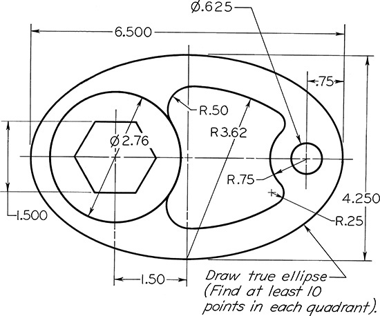
Exercise 3.9 Special Cam. Create a freehand sketch. Use the dimensions to help in estimating proportions. Leave the dimensions off your sketch unless directed otherwise by your instructor.

Exercise 3.10 Boiler Stay. Create a freehand sketch. Use the dimensions to help in estimating proportions. Leave the dimensions off your sketch unless directed otherwise by your instructor.

Exercise 3.11 Outside Caliper. Create a freehand sketch. Use the dimensions to help in estimating proportions. Leave the dimensions off your sketch unless directed otherwise by your instructor.
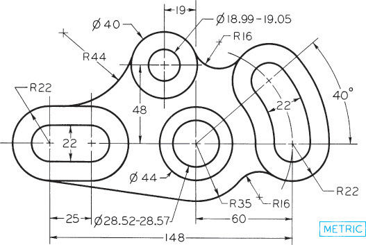
Exercise 3.12 Gear Arm. Create a freehand sketch. Use the dimensions to help in estimating proportions. Leave the dimensions off your sketch unless directed otherwise by your instructor.
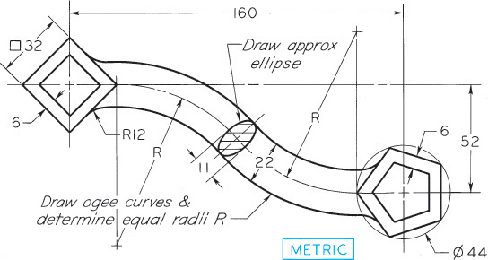
Exercise 3.13 Special S-Wrench. Create a freehand sketch. Use the dimensions to help in estimating proportions. Leave the dimensions off your sketch unless directed otherwise by your instructor.