
Chapter Nine. Auxiliary Views
Objectives
After studying the material in this chapter, you should be able to:
1. Create an auxiliary view from orthographic views.
2. Draw folding lines or reference-plane lines between any two adjacent views.
3. Construct depth, height, or width auxiliary views.
4. Plot curves in auxiliary views.
5. Construct partial auxiliary views.
6. Create auxiliary section views.
7. Produce views to show the true length of a line, point view of a line, edge view of a surface, and true-size view of a surface.
8. Show the true size of the angle between two planes (dihedral angle).
9. Construct the development of prisms, pyramids, cylinders, and cones.
10. Use triangulation to transfer surface shapes to a development.
11. Create the development of transition pieces.
12. Graphically solve for the intersection of solids.
13. Apply revolution to show true-length edges and true-size surfaces.
Refer to the following standard:
• ANSI/ASME Y14.3 Multiview and Sectional View Drawings

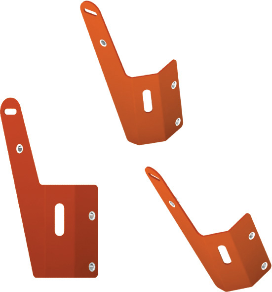
Auxiliary View Drawing. This switch mount uses an auxiliary view to show the true size of the inclined surface. (Courtesy of Big Sky Laser.)
Overview
Inclined planes and oblique lines do not appear true size or true length in any of the principal planes of projection. When it is necessary to show the true length of an oblique line or the true size of an inclined plane, an auxiliary view must be created. The principles for creating auxiliary views are the same whether you are using traditional drawing, sketching, or CAD: a line of sight and reference plane are defined. With traditional drawing, the view is manually created along line-of-sight projectors. With CAD drawing, the computer generates the view automatically if a 3D model of the object was originally created. Even if you are going to be using a CAD system to generate auxiliary views, it is important to understand the theory of developable surfaces. Some surfaces cannot be developed or “flattened out” to make an exact flat pattern for creating parts from sheet metal, cardboard packaging, or fabric. For example, a sphere can only be approximated. Understanding development methods can aid you in using your CAD software to the fullest extent.
Understanding Auxiliary Views
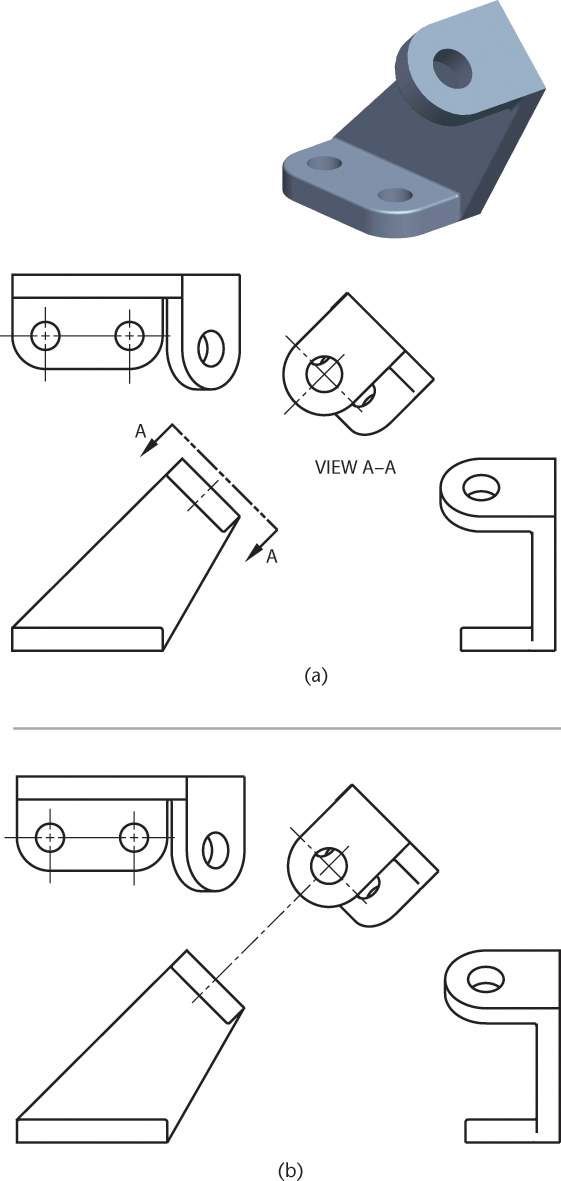
Auxiliary views are useful for both design and documentation. Many objects are shaped so that their principal faces are not parallel to the standard planes of projection. For example, in Figure 9.1a the base of the design for the bearing is shown in its true size and shape, but the rounded upper portion is at an angle, so it does not appear true size and shape in any of the three regular views. When creating a drawing for documentation, you will often need to show the true size and shape of surfaces and angles. Likewise, you may need to create true-size flat patterns for sheet metal, packaging, and other purposes.

To show the true circular shapes, use a direction of sight perpendicular to the plane of the curve, to produce a view as shown in Figure 9.1b. The result is an auxiliary view: an orthographic view that is not a standard projection. This view, together with the top view, completely describes the object. The front and right-side views are not necessary.
The Auxiliary Plane
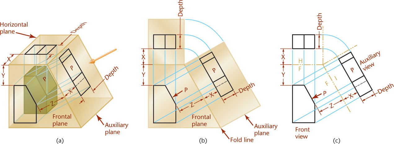
The object shown in Figure 9.2a has an inclined surface (P) that does not appear in its true size and shape in any regular view. To show the inclined surface true size, the direction of sight must be perpendicular to the inclined plane. Or using the glass box model, the auxiliary plane is aligned parallel to the inclined surface P to give a true-size view of it. The auxiliary plane in this case is perpendicular to the frontal plane of projection and hinged to it. It is angled to the horizontal (top) and profile (side) viewing planes.

The horizontal and auxiliary planes are unfolded into the plane of the front view, as shown in Figure 9.2b. Drawings do not show the planes of the glass box, but you can think of folding lines (H/F and F/A) representing the hinges that join the planes. The folding lines themselves are usually omitted in the actual drawing.
Inclined surface P is shown in its true size and shape in the auxiliary view. Note that both the top and auxiliary views show the depth of the object. One dimension of the surface is projected directly from the front view, and the depth is transferred from the top view.
The locations of the folding lines depend on the size of the glass box and the location of the object within it. If the object is farther down in the box, distance Y is increased. If the object is moved back in the box, distances X increase but are still equal. If the object is moved to the left inside the glass box, distance Z is increased.
Primary Auxiliary Views
Any view obtained by orthographic projection onto a plane other than the horizontal, frontal, and profile projection planes is an auxiliary view. A primary auxiliary view is projected onto a plane that is perpendicular to one of the principal planes of projection and is inclined to the other two. Figure 9.3 shows examples of primary auxiliary views.
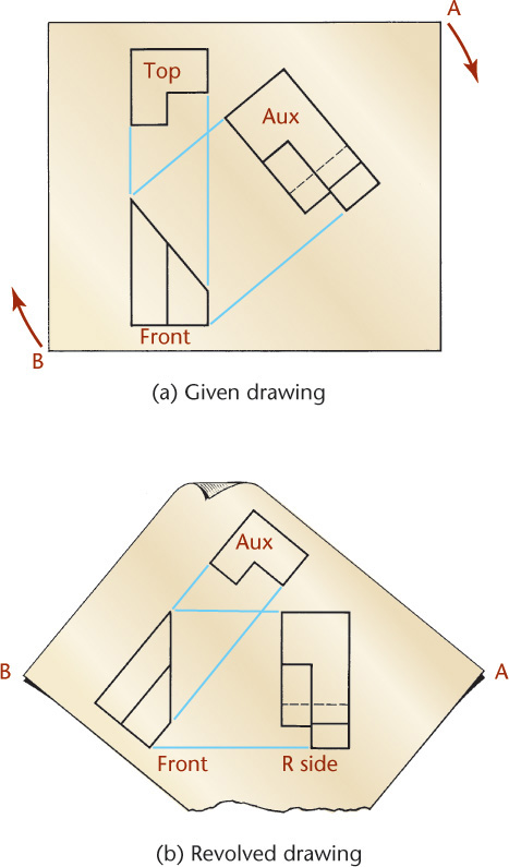
Visualizing an Auxiliary View as a Revolved Drawing
Figure 9.4a is a drawing showing top, front, and auxiliary views. Figure 9.4b shows the drawing revolved, as indicated by the arrows, until the auxiliary view and the front view line up horizontally. Although the views remain exactly the same, the names of the views are changed if drawn in this position. The auxiliary view now becomes a right-side view, and the top view becomes an auxiliary view. Sometimes it is easier to visualize and draw an auxiliary view when revolved to the position of a regular view in this manner. In any case, it should be understood that an auxiliary view is basically like any other view.
Classification of Auxiliary Views
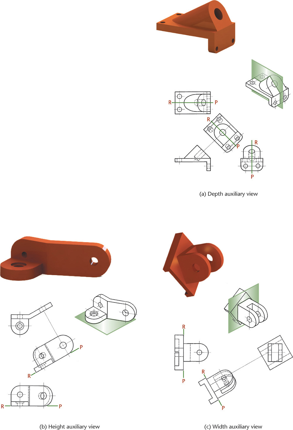
Auxiliary views are named for the principal dimension shown in the auxiliary view. For example, the auxiliary views in Figure 9.5 are depth auxiliary views because they show the object’s depth. Any auxiliary view projected from the front view, also known as a front adjacent view, is a depth auxiliary view.
Similarly, any auxiliary view projected from the top view, also known as a top adjacent view, is a height auxiliary view; and any auxiliary view projected from a side view, also known as a side adjacent view, is a width auxiliary view.
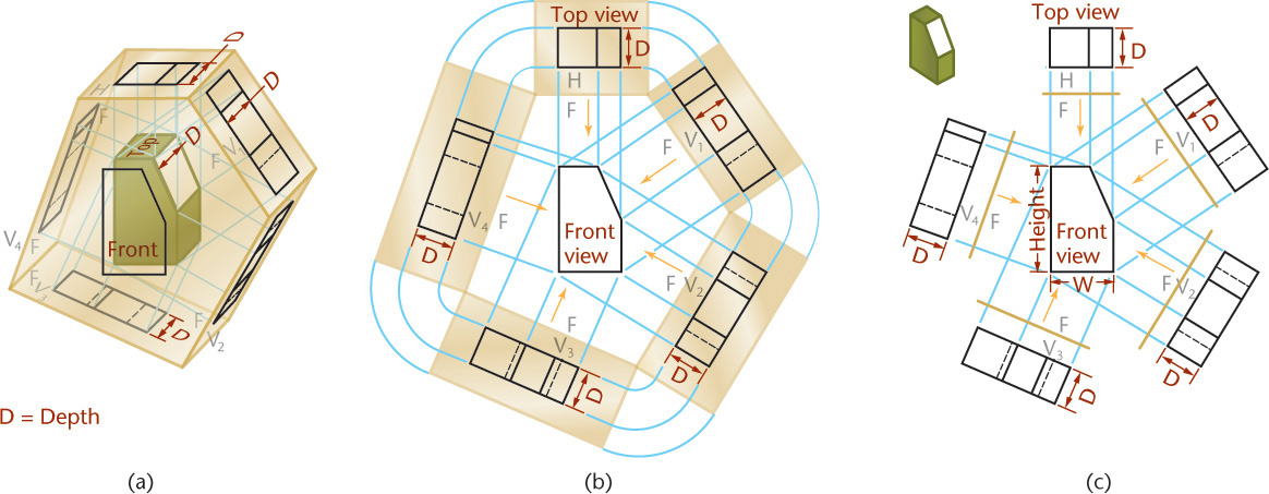
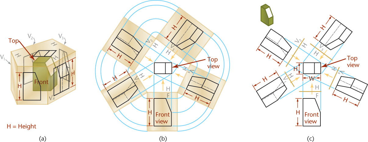
Depth Auxiliary Views
An infinite number of auxiliary planes can be hinged perpendicular to the frontal plane (F) of projection. Five such planes are shown in Figure 9.5a. The horizontal plane is included to show that it is similar to the others. All these views show the object’s depth and therefore are all depth auxiliary views.
The unfolded auxiliary planes, shown in Figure 9.5b, show how depth dimensions are projected from the top view to all auxiliary views. The arrows indicate the directions of sight.
The complete drawing, with the outlines of the planes of projection omitted, is shown in Figure 9.5c. Note that the front view shows the height and the width of the object, but not the depth. The principal dimension shown in an auxiliary view is the one not shown in the adjacent view from which the auxiliary view was projected.
Height Auxiliary Views
An infinite number of auxiliary planes can be hinged perpendicular to the horizontal plane (H) of projection. Several are shown in Figure 9.6a. The front view and all these auxiliary views show the height of the object. Therefore, all these auxiliary views are height auxiliary views.
The unfolded projection planes are shown in Figure 9.6b, and the complete drawing is shown in Figure 9.6c. Note that in the top view, the only dimension not shown is height.
Width Auxiliary Views
An infinite number of auxiliary planes can also be hinged perpendicular to the profile plane (P) of projection. Some are shown in Figure 9.7. The front view and all these auxiliary views are width auxiliary views.
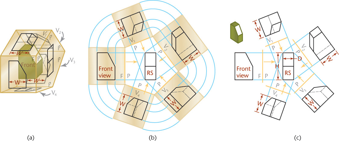
The unfolded planes are shown in Figure 9.7b, and the complete drawing is shown in Figure 9.7c. In the right-side view, from which the auxiliary views are projected, the only dimension not shown is width.
Successive Auxiliary Views
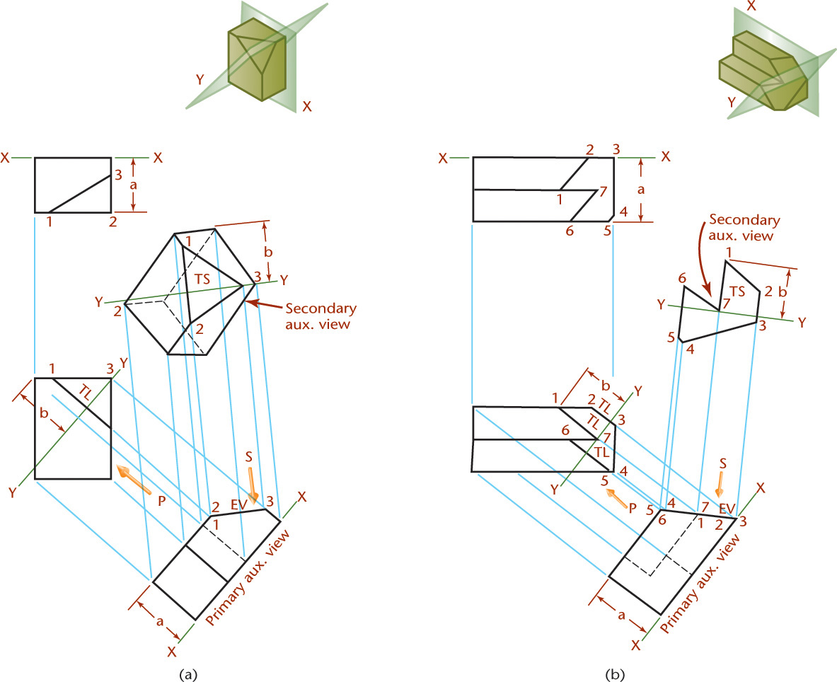
Primary auxiliary views are projected from one of the principal views. In Figure 9.8, auxiliary view 1 is a primary auxiliary view projected from the top view.

From primary auxiliary view 1 a secondary auxiliary view 2 can be drawn, then from it a third auxiliary view 3, and so on. An infinite number of such successive auxiliary views may be drawn. However, secondary auxiliary view 2 is not the only one that can be projected from primary auxiliary view 1. As shown by the arrows around view 1, an infinite number of secondary auxiliary views, with different lines of sight, may be projected. Any auxiliary view projected from a primary auxiliary view is a secondary auxiliary view. Furthermore, any succeeding auxiliary view may be used to project an infinite series of views from it.
In this example, folding lines are more convenient than reference-plane lines. In auxiliary view 1, all numbered points of the object are the same distance from folding line H/V1 as they are in the front view from folding line H/F. These distances, such as distance a, are transferred from the front view to the auxiliary view.
To draw the secondary auxiliary view 2, ignore the front view and focus on the sequence of three views: the top view, view 1, and view 2. Draw light projection lines parallel to the direction of sight desired for view 2. Draw folding line V1/V2 perpendicular to the projection lines and at any convenient distance from view 1. Transfer the distances measured from folding line H/V1 to locate all points in view 2. For example, transfer distance b to locate points 4 and 5 from folding line V1/V2. Connect points to draw the object and determine visibility. The closest corner (11) in view 2 will be visible, and the one farthest away (1) will be hidden, as shown.
To draw views 3, 4, and so on, use a similar process. Remember to use the correct sequence of three views.
Secondary Auxiliary Views
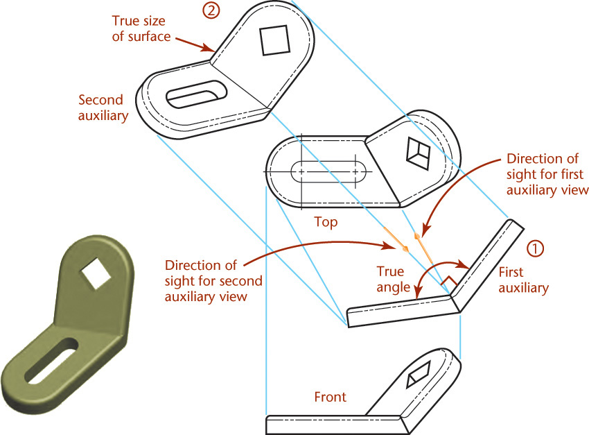
A secondary auxiliary view is projected from a primary auxiliary view onto a plane that is inclined to all three principal projection planes. As shown in Figure 9.9, a part that has an oblique surface often requires a second auxiliary view to show that surface’s true size and shape. In this case, the primary auxiliary view shows the oblique plane on edge.
Reference Planes
In the auxiliary view shown in Figure 9.10c, the folding line represents the edge view of the frontal plane of projection. In this case, the frontal plane is used for transferring distances—that is, depth measurements—from the top view to the auxiliary view.
Tip
If you are using 2D CAD, you can draw half of the view and then mirror the object.
Instead of using one of the planes of projection, you can use a reference plane parallel to the plane of projection that touches or cuts through the object. For example, in Figure 9.11a, a reference plane is aligned with the front surface of the object. This plane appears on edge, as a line, in the top and auxiliary views. Measurements are made from the reference lines. The depth dimensions in the top view and auxiliary views are equal. The advantage of the reference-plane method is that fewer measurements are required, because some points of the object lie in the reference plane. Make the reference plane using light lines similar to construction lines.

You can use a reference plane that coincides with the front surface of the object, as shown in Figure 9.11a. When an object is symmetrical, it is useful to select the reference plane to cut through the object, as shown in Figure 9.11b. This way you have to make only half as many measurements to transfer dimensions because they are the same on each side of the reference plane. You can also use the back surface of the object, as shown in Figure 9.11c, or any intermediate point that would be advantageous.
Position the reference plane so it is convenient for transferring distances. Remember the following:
1. Reference lines, like folding lines, are always at right angles to the projection lines between the views.
2. A reference plane appears as a line in two alternate views, never in adjacent views.
3. Measurements are always made at right angles to the reference lines or parallel to the projection lines.
4. In the auxiliary view, all points are at the same distances from the reference line as the corresponding points are from the reference line in the alternate view, or the second previous view.
Step by Step: Projecting an Auxiliary View

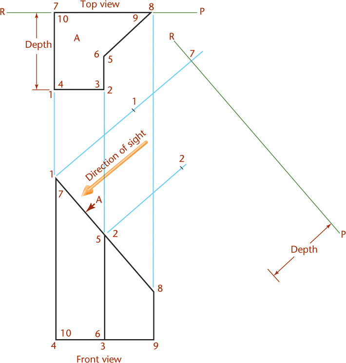
The object has been numbered in the pictorial view to aid in keeping track of the vertices. To create an auxiliary view of surface A, follow these steps.
![]() Draw two views of the object and determine the direction of sight needed to produce a view that will show the true size of surface A.
Draw two views of the object and determine the direction of sight needed to produce a view that will show the true size of surface A.
Next, sketch projection lines parallel to the direction of sight.
Establish a reference plane. In this case the back surface of the object will work well. The reference lines in the top and auxiliary views are at right angles to the projection lines. These are the edge views of the reference plane, RP.
![]() The auxiliary view of surface A will be true size and shape because the direction of sight is perpendicular to that surface. Transfer depth measurements from the top view to the auxiliary view. Each point in the auxiliary view will be on its projection line extended from the front view. The point will be the same distance from the reference line in the top view to the corresponding reference line in the auxiliary view. Finish projecting points 5 and 8.
The auxiliary view of surface A will be true size and shape because the direction of sight is perpendicular to that surface. Transfer depth measurements from the top view to the auxiliary view. Each point in the auxiliary view will be on its projection line extended from the front view. The point will be the same distance from the reference line in the top view to the corresponding reference line in the auxiliary view. Finish projecting points 5 and 8.
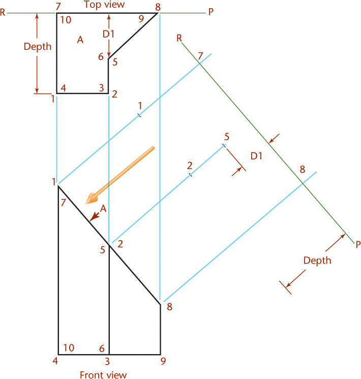
![]() Draw surface A true size in the auxiliary view by connecting the vertices in the same order as they are shown connecting in the top view (1-7-8-5-2-1).
Draw surface A true size in the auxiliary view by connecting the vertices in the same order as they are shown connecting in the top view (1-7-8-5-2-1).
Complete the auxiliary view by adding other visible edges and surfaces of the object. Each numbered point in the auxiliary view lies on its projection line from the front view and is the same distance from the reference line as it is in the top view. Note that two surfaces of the object appear as lines in the auxiliary view.

9.1 Using Triangles to Sketch Auxiliary Views
You can use two triangles to quickly draw parallel and perpendicular lines for “accurate” sketches.
• Place two triangles together so that the 90° corners are on the outside, as shown in Figure 9.12.
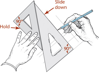
• Slide them on your drawing until the outer edge of one triangle is along the line to which you want to sketch parallel.
• Hold down the triangle and slide the other along it.
• Draw parallel lines along one edge of the triangle. Draw perpendicular lines along the other edge.
This technique works well as an addition to freehand sketching when you want to show an auxiliary view.
9.2 Using Grid Paper to Sketch Auxiliary Views
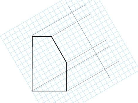
You can use grid paper to help sketch auxiliary views by orienting the lines of the grid paper underneath your vellum or other semitransparent drawing sheet so that the grid is parallel to the inclined edge in the drawing, as shown in Figure 9.13. Use the grid to help sketch lines parallel and perpendicular to the edge in question.
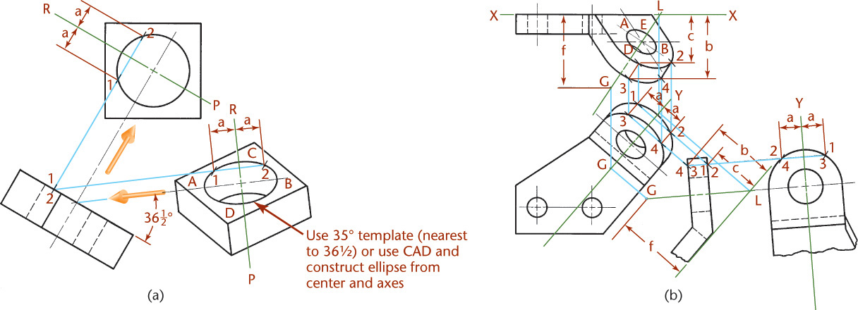
Step by Step: Showing an Inclined Elliptical Surface True Size
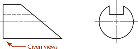
Given the front and side views shown, use these steps to project an auxiliary view showing the true size of the elliptical surface.
![]() Because this is a symmetrical object, use a reference plane through the center of the object, as shown.
Because this is a symmetrical object, use a reference plane through the center of the object, as shown.

![]() Select points on the circle in the side view.
Select points on the circle in the side view.

![]() Locate the same points on the inclined surface and the left-end surface.
Locate the same points on the inclined surface and the left-end surface.

Given Views
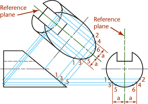
![]() Project each point to the auxiliary view along its projection line. In this case, the direction of sight is perpendicular to the edge view of the inclined surface. This will produce an auxiliary view showing the true shape of that surface.
Project each point to the auxiliary view along its projection line. In this case, the direction of sight is perpendicular to the edge view of the inclined surface. This will produce an auxiliary view showing the true shape of that surface.
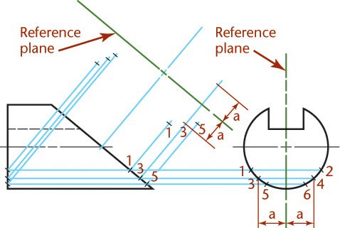
![]() Transfer distances from the side view to the auxiliary view. Because the object is symmetrical, two points can be located with each measurement, as shown for points 1–2, 3–4, and 5–6. Project enough points to sketch the curves accurately.
Transfer distances from the side view to the auxiliary view. Because the object is symmetrical, two points can be located with each measurement, as shown for points 1–2, 3–4, and 5–6. Project enough points to sketch the curves accurately.
Because the major and minor axes are known, you can quickly create similar ellipses using CAD by locating the major and minor axes or the center and axes. For hand sketching, you may want to use an ellipse template.
9.3 Using CAD to Create Auxiliary Views
Most CAD systems allow you to rotate the grid or to create a new coordinate system (often called a user coordinate system) so that it aligns with the inclined surface. If you are using 3D CAD, you can create true-size auxiliary views by viewing the object perpendicular to the surface you want to show true size (see Figure 9.14).
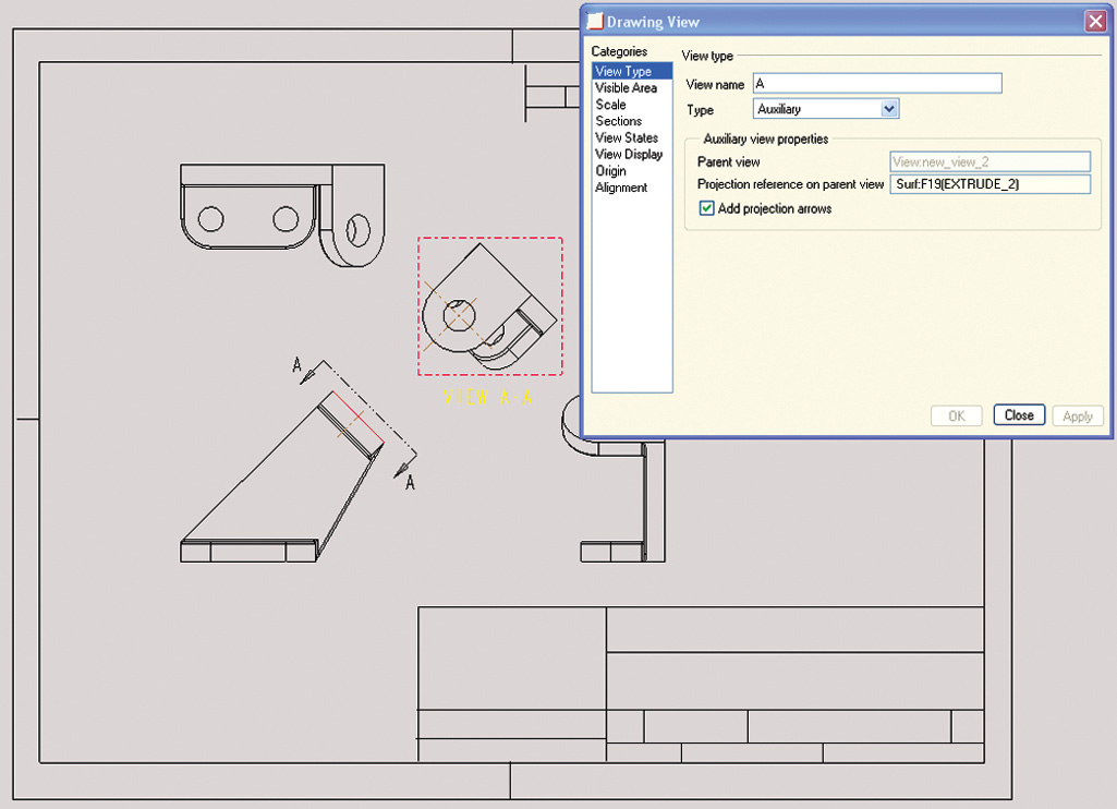
9.14 CAD software provides tools for generating auxiliary views. (Courtesy of SolidWorks Corporation.)
9.4 Circles and Ellipses in Auxiliary Views
Circular shapes appear elliptical when viewed at an angle other than 90° (straight on to the circular shape). This is frequently the case when constructing auxiliary views (Figure 9.15).
9.5 Hidden Lines in Auxiliary Views
Generally, hidden lines should be omitted in auxiliary views, unless they are needed to clearly communicate the drawing’s intent. Note the use of hidden lines in Figure 9.16.
Tip
Your instructor may ask you to show all hidden lines for visualization practice, especially if the auxiliary view of the entire object is shown. Later, when you are familiar with drawing auxiliary views, omit hidden lines when they do not add needed information to the drawing.
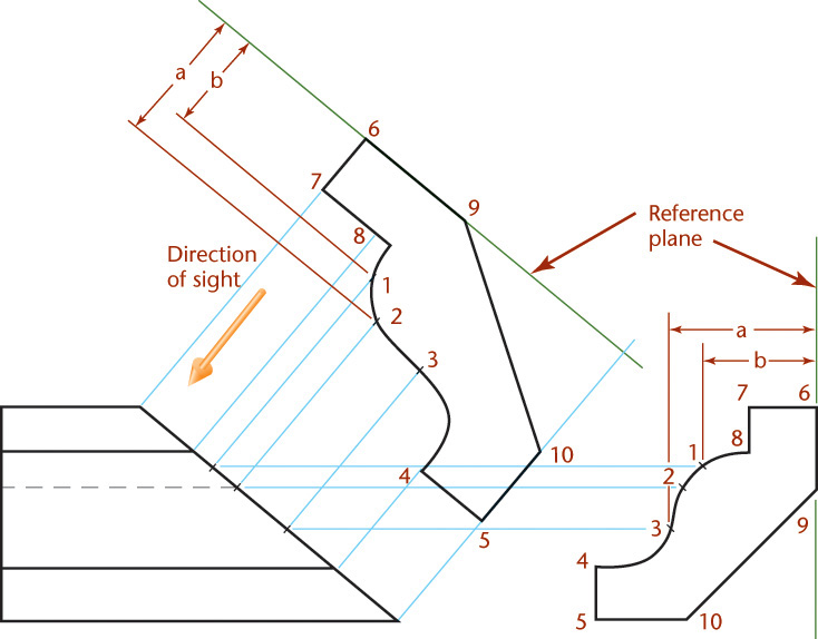
Step by Step: Plotting Curves Manually in an Auxiliary View
Use the following steps to manually create an auxiliary view that shows the true size and shape of an inclined cut through a piece of molding. The method of plotting points is similar to that explained for the ellipse.
![]() Identify some points along the curve shown in the side view. Locate those same points in the front view.
Identify some points along the curve shown in the side view. Locate those same points in the front view.

![]() Locate the reference plane. Draw projectors perpendicular to the inclined surface in the front view and project the points into the auxiliary view.
Locate the reference plane. Draw projectors perpendicular to the inclined surface in the front view and project the points into the auxiliary view.
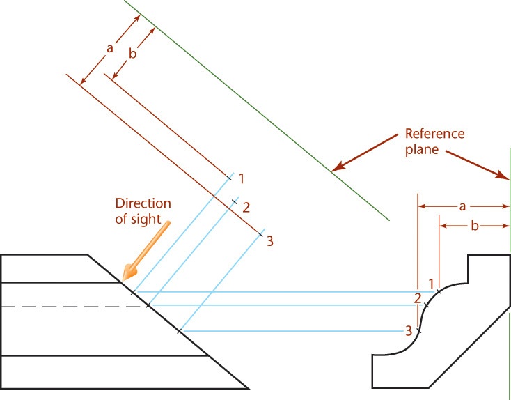
![]() Finish projecting all of the points on the inclined surface and draw its true shape in the auxiliary view.
Finish projecting all of the points on the inclined surface and draw its true shape in the auxiliary view.
9.6 Partial Auxiliary Views
Using an auxiliary view often makes it possible to omit one or more regular views, but auxiliary drawings are time consuming to create and may even be confusing because of the clutter of lines.
Partial views are often sufficient and easier to read. Figure 9.17 shows partial regular views and partial auxiliary views. Usually, a break line is used to indicate the imaginary break in the views. Do not draw a break line coinciding with a visible line or hidden line.
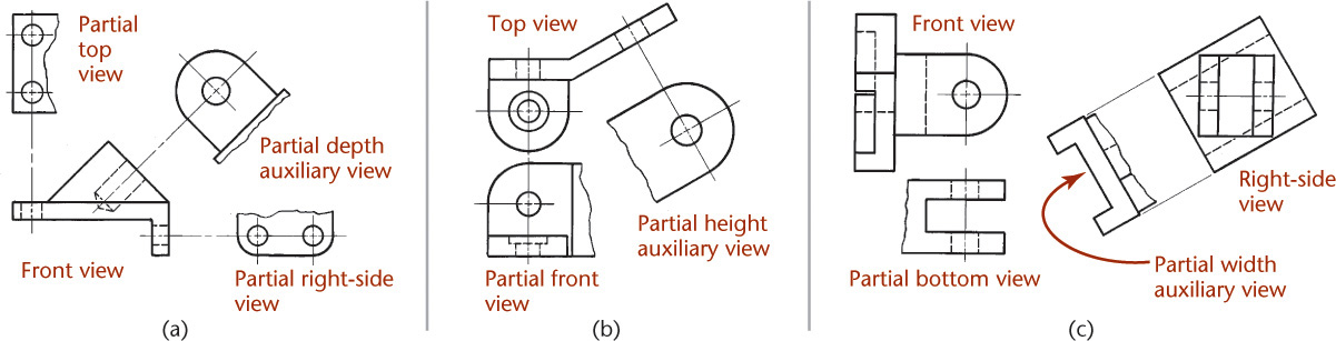
So that partial auxiliary views (which are often small) do not appear “lost” and unrelated to any view, connect them to the views from which they project, either with a centerline or with one or two thin projection lines as shown in Figure 9.17.
9.7 Half Auxiliary Views
If an auxiliary view is symmetrical, and if it is necessary to save space on the drawing or to save time, a half auxiliary view may be drawn, as shown in Figure 9.18. In this case, half of a regular view is also shown, since the bottom flange is also symmetrical. Note that in each case the near half is shown.

9.8 Reverse Construction
To complete the regular views, it is often necessary to first construct an auxiliary view where critical dimensions will be shown true size. For example, in Figure 9.19a, the upper part of the right-side view cannot be constructed until the auxiliary view is drawn. First, points are established on the curves and then projected back to the front view.
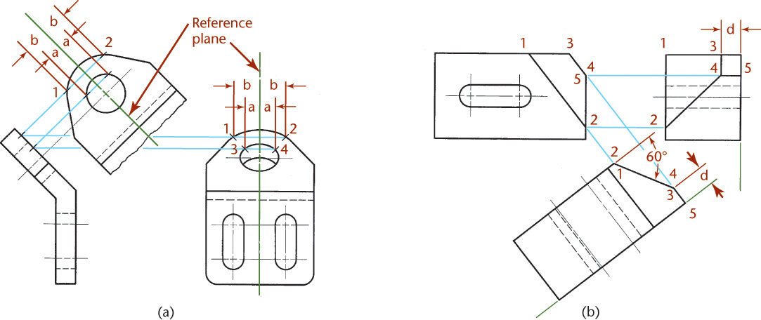
In Figure 9.19b, the 60° angle and the location of line 1–2 in the front view are given. To locate line 3–4 in the front view and lines 2–4, 3–4, and 4–5 in the side view, you must first construct the 60° angle in the auxiliary view and project it back to the front and side views, as shown.
9.9 Auxiliary Sections
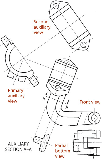
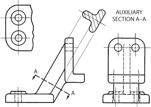
An auxiliary section is simply an auxiliary view in section (see Figure 9.20). A typical auxiliary section is shown in Figure 9.22. In this example, there is not sufficient space for a revolved section, although a removed section could have been used instead of an auxiliary section. Note the cutting-plane line and the terminating arrows that indicate the direction of sight for the auxiliary section. In an auxiliary section drawing, the entire portion of the object behind the cutting plane may be shown, or the cut surface alone may be shown.

The cutting-plane line indicates both the location of the cutting plane and the direction of sight for the auxiliary section. Figures 9.21 and 9.22 show examples of this. Notice that the auxiliary section is shown in alignment. Typically, a centerline is extended to locate the auxiliary sections or a few projection lines are shown in the drawing for this purpose.
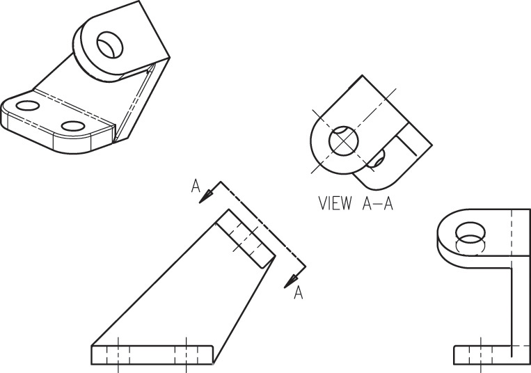
9.10 Viewing-Plane Lines and Arrows
When the drawing sheet is too crowded to show the auxiliary view in direct projection you can use a viewing-plane line or a viewing direction arrow to indicate the direction of sight for the auxiliary view.
A viewing-plane line and a cutting-plane line look essentially the same. The arrows on either end of the line point in the direction of sight for the removed view. The ends of the line are labeled with letters, starting with A, then B, and so on. The auxiliary view, when placed in a removed location, should still be shown in the same orientation it would have if it were aligned in projection. Figure 9.23a shows a removed auxiliary view and viewing-plane line.
9.23 Using a Viewing-Plane Line to Show the Direction of Sight for an Auxiliary View. Alternatively, a centerline can be extended to indicate the viewing direction.
A viewing direction arrow for a removed auxiliary view is essentially the same as for any other removed view. Show an arrow pointing in the direction of sight for the removed auxiliary view. Label the removed view and place it in the same orientation it would have when projected, or if it is rotated, show a rotation arrow and specify the amount of rotation.
A centerline can be extended from a hole or other symmetric feature to indicate the alignment of the auxiliary view, as shown in Figure 9.23b.
Viewing direction arrows are particularly useful when showing a second auxiliary view in a drawing that is created from a 3D CAD model. Often, the primary auxiliary view is not necessary and can be left out if a viewing direction arrow is shown indicating the direction of sight for the second auxiliary view. An example of this use of a viewing direction arrow in a CAD drawing is shown in Figure 9.24.

9.11 Uses of Auxiliary Views
Generally, auxiliary views are used to show the true shape or true angle of features that appear distorted in the regular views. Auxiliary views are often used to produce views that show the following:
1. True length of line
2. Point view of line
3. Edge view of plane
4. True size of plane
You can use the ability to generate views that show the specific items listed to solve a variety of engineering problems. Descriptive geometry is the term for using accurate drawings to solve engineering problems. An accurate CAD drawing database can be used to solve many engineering problems when you understand the four basic views from descriptive geometry. Using 3D CAD, you can often model objects accurately and query the database for lengths and angles. Even so, you will often need the techniques described next to produce views that will help you visualize, create, or display 3D drawing geometry.
9.12 True Length of a Line
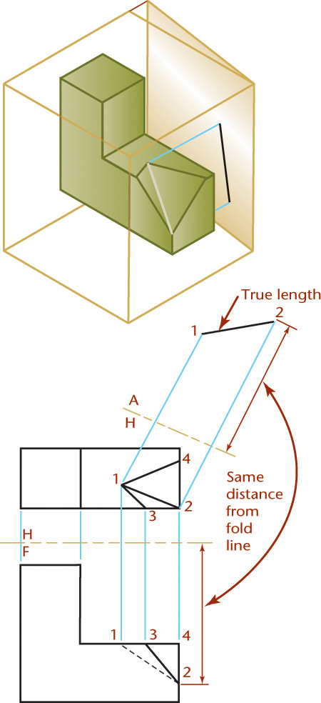
As shown in Figure 9.25, a line will show true length in a plane of projection that is parallel to the line. In other words, a line will show true length in an auxiliary view where the direction of sight is perpendicular to the line. To show a line true length, make the fold line parallel to the line you want to show true length in the auxiliary view. Whenever a line is parallel to the fold line between two views, it will be true length in the adjacent view.
Tip: The Need to Show the True Length of a Line in CAD

The slope of a guy wire can be determined when you see its true length. Foreshortened views do not show the actual angle.
Whether you are using 2D or 3D CAD or creating a sketch or drawing by hand, it is often necessary to create a view that shows a certain line true length. For example, a line must appear true length if you want to find its slope.
When you are working in a 3D CAD program, it is generally easy to list the true length of a line or an edge; but knowing the dimension is not the same as being able to show it on a drawing so that others can correctly interpret it.
To annotate the dimension on a drawing view where the line in question is shown true length you must understand how to create a view that is parallel to the line.
If you use 2D CAD, you will use the same methods explained in this chapter. If you use 3D CAD, reading about how to show a line at true length will help you understand how to create a plane parallel to that line in 3D CAD.
Understanding when a line is true length and when it is foreshortened in a view is also helpful in developing your ability to accurately visualize a 3D object from a 2D drawing.
Step by Step: Showing the True Length of a Hip Rafter
The top and front views of the hip rafter (line 1–2) are shown. Use an auxiliary view to show the line true length.
![]() Choose the direction of sight to be perpendicular to line 1–2 (front view).
Choose the direction of sight to be perpendicular to line 1–2 (front view).

![]() Draw the H/F folding line between the top and front views, as shown.
Draw the H/F folding line between the top and front views, as shown.
![]() Draw the F/V1 folding line parallel to line 1–2 and any convenient distance from line 1–2 (front view).
Draw the F/V1 folding line parallel to line 1–2 and any convenient distance from line 1–2 (front view).

![]() Draw projection lines from points 1, 2, and 3 to begin creating the auxiliary view.
Draw projection lines from points 1, 2, and 3 to begin creating the auxiliary view.

![]() Transfer points 1 and 2 to the auxiliary view at the same distance from the folding line as they are in the top view, and along their respective projection lines. The hip rafter (line 1–2) is shown true length in the auxiliary view.
Transfer points 1 and 2 to the auxiliary view at the same distance from the folding line as they are in the top view, and along their respective projection lines. The hip rafter (line 1–2) is shown true length in the auxiliary view.
Also, triangle 1–2–3 in the auxiliary view shows the true size and shape of that portion of the roof because the direction of sight for the auxiliary view is perpendicular to triangle 1–2–3.

9.13 Point View of a Line
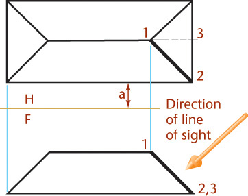
As shown in Figure 9.26, a line will show as a point view when projected to a plane perpendicular it. To show the point view of a line, choose the direction of sight parallel to the line where it is true length.
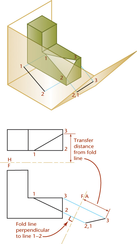
Showing the Point View of a Line
Refer to Figure 9.27 for the following steps:
1. Choose the direction of sight to be parallel to line 1–2.
2. Draw folding line H/F between the top and front views, as shown.
3. Draw folding line F/A perpendicular to line 1–2 where it is true length, and any convenient distance from line 1–2 (front view).
4. Draw projection lines from points 1 and 2 to begin creating the auxiliary view.
5. Transfer points 1 and 2 to the auxiliary view at the same distance from the folding line as they are in the top view and along their respective projection lines. They will line up exactly with each other to form a point view of the line.

Tip: Viewing a Line as a Point
Draw a line in a plane—for example, a straight line on a sheet of paper. Then, tilt the paper to view the line as a point. You will see that when the line appears as a point, the plane containing it appears as a line. (Because your paper will end up being viewed on edge, it may be a little hard to see the line when it is oriented correctly.)

9.14 Edge View of a Plane
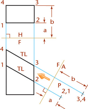
As shown in Figure 9.28, a plane will show on edge in a plane of projection that shows a point view of any line that lies entirely within the plane. To get the point view of a line, the direction of sight must be parallel to the line where it is true length. To show the edge view of a plane, choose the direction of sight parallel to a true-length line lying in the plane.

Finding the edge view of a plane is a useful tool for the following types of problems:
• Finding the shortest line from a point to a plane. The shortest line will be perpendicular from the point to the plane. This is easiest to show in a view showing the plane on edge.
• Finding the slope of a plane. When you are working in a 3D CAD program, it is easy to create a view from any direction. Understanding how to choose a direction that will produce the most useful view for your purposes is easier yet when you understand these basic principles. Even though you can use CAD inquiry tools to quickly determine the angle between planes, often you may need to document the angle of a plane in a view showing the plane on edge.
Showing the Edge View of a Plane
Refer to Figure 9.29 for the following steps:
1. Choose the direction of sight to be parallel to line 1–2 in the front view where it is already shown true length.
2. Draw folding line H/F between the top and front views, as shown.
3. Draw folding line F/A perpendicular to true-length line 1–2 and any convenient distance.
4. Draw projection lines from points 1, 2, and 3 to begin creating the auxiliary view.
5. Transfer points 1, 2, and 3 to the auxiliary view at the same distance from the folding line as they are in the top view and along their respective projection lines. Plane 1–2–3 will appear on edge in the finished drawing.
9.15 True Size of an Oblique Surface
As shown in Figure 9.30, a plane will show true size when the plane of projection is parallel to it.
To show the true size view of a plane, choose the direction of sight perpendicular to the edge view of the plane.
Showing the true size of a surface continues from the method presented for showing inclined surfaces true size, where the edge view is already given. But to show an oblique surface true size, you need first to show the oblique surface on edge and then construct a second auxiliary view to show it true size.
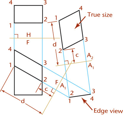
Showing the True Size and Shape of an Oblique Surface
To show the true size and shape of an oblique surface, such as surface 1–2–3 in Figure 9.31, create a second auxiliary view. In this example folding lines are used, but you can achieve the same results for all of the preceding examples using reference lines.

1. Draw the auxiliary view showing surface 1–2–3 on edge, as explained previously.
2. Create a second auxiliary view with the line of sight perpendicular to the edge view of plane 1–2–3 in the primary auxiliary view. Project lines parallel to the arrow. Draw folding line A1/A2 perpendicular to these projection lines at a convenient distance from the primary auxiliary view.
3. Draw the secondary auxiliary view. Transfer the distance to each point from folding line F/A1 to the second auxiliary view—for example, dimensions d1, d2, and d3. The true size TS of the surface 1–2–3 is shown in the secondary auxiliary view, because the direction of sight is perpendicular to it.
Figure 9.32 shows an example of the steps to find the true size of an oblique surface. The first step, illustrated in Figure 9.32a, shows the oblique surface on edge. Figure 9.32b establishes the direction of sight perpendicular to the edge view. The final true size view of the surface is projected in Figure 9.32c.
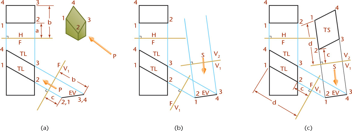
Figure 9.33 shows a similar example using the reference-plane method.
9.16 Dihedral Angles
The angle between two planes is called a dihedral angle. Auxiliary views often need to be drawn to show dihedral angles true size, mainly for dimensioning purposes. In Figure 9.34a, a block with a V-groove is shown where the dihedral angle between inclined surfaces A and B is shown true size in the front view.

In Figure 9.34b, the V-groove on the block is at an angle to the front surface so that the true dihedral angle is not shown. Assume that the actual angle is the same as in Figure 9.34a. Does the angle appear larger or smaller than in Figure 9.34a?
To show the true dihedral angle, the line of intersection (in this case 1–2) must appear as a point. Because the line of intersection for the dihedral angle is in both planes, showing it as a point will produce a view which shows both planes on edge. This will give you the true-size view of the dihedral angle.
In Figure 9.34a, line 1–2 is the line of intersection of planes A and B. Now, line 1–2 lies in both planes at the same time; therefore, a point view of this line will show both planes as lines, and the angle between them is the dihedral angle between the planes. To get the true angle between two planes, find the point view of the line of intersection of the planes.
In Figure 9.34c, the direction of sight is parallel to line 1–2 so that line 1–2 appears as a point, planes A and B appear as lines, and the true dihedral angle is shown in the auxiliary view.
Figure 9.35 shows a drawing using an auxiliary view to show the true angle between surfaces.

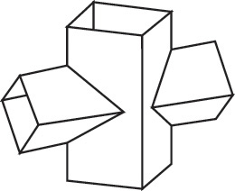
Understanding Developments and Intersections
A development is a flat representation or pattern that when folded together creates a 3D object (Figure 9.36). An intersection is the result of two objects that intersect each other (Figure 9.37). Sheet metal construction is the most common application for developments and intersections. A development of surfaces, such as those found in sheet metal fabrication, is a flat pattern that represents the unfolded or unrolled surface of the form. The resulting flat pattern gives the true size of each connected area of the form so that the part or structure can be fabricated. Auxiliary views are a primary tool for creating developments, but many specialized software packages are available to automate creating developments and intersections. You can also apply what you have learned about auxiliary views to create developments and intersections using your CAD system.

Surface Terminology
The following terminology describes objects and concepts used in developments and intersections:
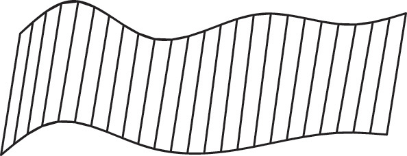
A ruled surface is one that may be generated by sweeping a straight line, called the generatrix, along a path, which may be straight or curved (Figure 9.38). Any position of the generatrix is an element of the surface. A ruled surface may be a plane, a single-curved surface, or a warped surface.
A plane is a ruled surface that is generated by a line, one point of which moves along a straight path while the generatrix remains parallel to its original position. Many geometric solids are bounded by plane surfaces (Figure 9.39).

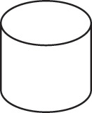
A single-curved surface is a developable ruled surface; that is, it can be unrolled to coincide with a plane. Any two adjacent positions of the generatrix lie in the same plane. Examples are the cylinder (Figure 9.40) and the cone.
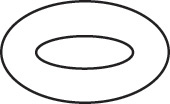
A double-curved surface is generated by a curved line and has no straight-line elements (Figure 9.41). A surface generated by revolving a curved line about a straight line in the plane of the curve is called a double-curved surface of revolution. Common examples are the sphere, torus, ellipsoid, and hyperboloid.
A warped surface is a ruled surface that is not developable. Some examples are shown in Figure 9.42. No two adjacent positions of the generatrix lie in a flat plane. Warped surfaces cannot be unrolled or unfolded to lie flat. Many exterior surfaces on an airplane or automobile are warped surfaces.
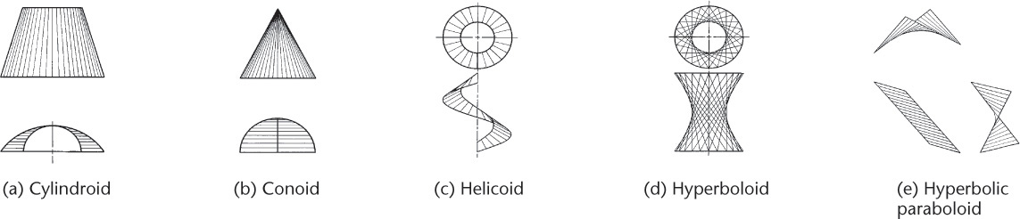
Developable Surfaces
A developable surface may be unfolded or unrolled to lie flat. Surfaces composed of single-curved surfaces, of planes, or of combinations of these types are developable.
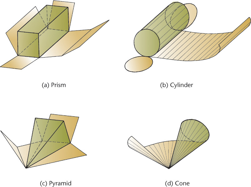
Warped surfaces and double-curved surfaces are not directly developable. They may be developed by approximating their shape using developable surfaces. If the material used in the actual manufacturing is sufficiently pliable, the flat sheets may be stretched, pressed, stamped, spun, or otherwise forced to assume the desired shape. Nondevelopable surfaces are often produced by a combination of developable surfaces that are then formed slightly to produce the required shape. Figure 9.43 shows examples of developable surfaces.
Principles of Intersections
Accurate drawings showing the intersections of planes and solids are needed for openings in roof surfaces for flues and stacks; openings in wall surfaces for pipes, chutes, and so on; and the building of sheet metal structures such as tanks and boilers. In such cases, you generally need to determine the true size and shape of the intersection of a plane and one of the more common geometric solids. Figure 9.44 shows an example in which you would need to determine the intersection of a solid and a plane to create the correctly shaped opening in the vertical prism—the main flue—where the horizontal prism joins it.
For solids bounded by plane surfaces, you need find only the points of intersection of the edges of the solid with the plane and to join these points, in consecutive order, with straight lines.
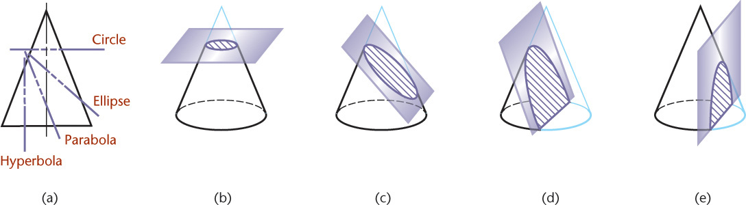
For solids bounded by curved surfaces, it is necessary to find the points of intersection of several elements of the solid with the plane and to trace a smooth curve through these points. The intersection of a plane and a circular cone is called a conic section. Some typical conic sections are shown in Figure 9.45.
9.17 Developments
The development of a surface is that surface laid out on a plane. Practical applications of developments occur in sheet metal work, stone cutting, pattern making, packaging, and package design. See Figure 9.46.
Single-curved surfaces and the surfaces of polyhedra can be developed. Developments for warped surfaces and double-curved surfaces can only be approximated.
In sheet metal layout, extra material must be provided for laps and seams. If the material is heavy, the thickness may be a factor, and the crowding of metal in bends must be considered. Stock sizes must also be taken into account and layouts made to economize on material and labor. In preparing developments, it is best to put the seam at the shortest edge and to attach the bases at edges where they match; this will minimize processing such as soldering, welding, and riveting.
It is common to draw development layouts with the inside surfaces up. This way, all fold lines and other markings are related directly to inside measurements, which are the important dimensions in all ducts, pipes, tanks, and vessels. In this position they are also convenient for use in the fabricating shop. See Sections 10.6 and 11.43 for more information about sheet metal bends.
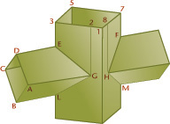
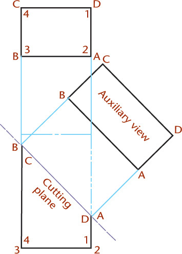
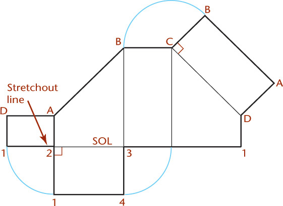
Finding the Intersection of a Plane and a Prism and Developing the Prism
To create flat patterns for sheet metal, packaging, and other purposes, you must first determine the true size of the surface. The true size and shape of the intersection of a plane and a prism is shown in the auxiliary view in Figure 9.47. The length AB is the same as AB in the front view, and the width AD is the same as AD in the top view.
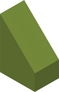
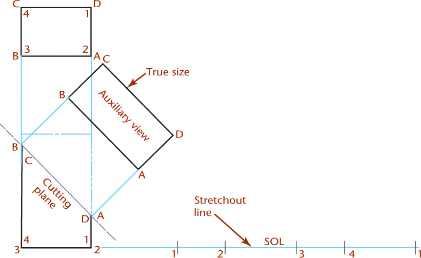
Step by Step: Developing a Prism
These are the steps for creating the development for the prism shown here.
![]() Draw the stretchout line, which represents the axis along which the part is unfolded or unrolled. On the stretchout line, transfer the true sizes of faces 1–2 and 2–3, which are shown true length in the top view. Remember that a line appears true length when the view is perpendicular to the line. In other words, when a line is parallel to the fold line between views, the line is true length in the adjacent view.
Draw the stretchout line, which represents the axis along which the part is unfolded or unrolled. On the stretchout line, transfer the true sizes of faces 1–2 and 2–3, which are shown true length in the top view. Remember that a line appears true length when the view is perpendicular to the line. In other words, when a line is parallel to the fold line between views, the line is true length in the adjacent view.
![]() Where two surfaces join, draw perpendiculars to the stretchout line and transfer the true height of each respective edge. The front view shows the true heights in this case. Project the heights from the front view, as shown. Complete the development of these surfaces using straight lines to join the points you have plotted. Identify other surfaces that are connected to these and attach their true sizes to the development of the lower base and the upper base. Use an auxiliary view to find the true size of the surface and then draw it in place.
Where two surfaces join, draw perpendiculars to the stretchout line and transfer the true height of each respective edge. The front view shows the true heights in this case. Project the heights from the front view, as shown. Complete the development of these surfaces using straight lines to join the points you have plotted. Identify other surfaces that are connected to these and attach their true sizes to the development of the lower base and the upper base. Use an auxiliary view to find the true size of the surface and then draw it in place.
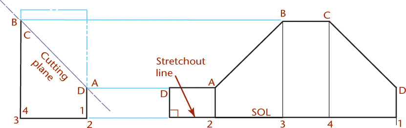
![]() When you finish, you will have drawn the development of the entire prism, as shown. If needed, add tabs so that there is material to connect the surfaces when folded up.
When you finish, you will have drawn the development of the entire prism, as shown. If needed, add tabs so that there is material to connect the surfaces when folded up.
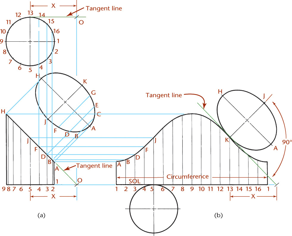
Finding the Intersection of a Plane and a Cylinder and Developing the Cylinder
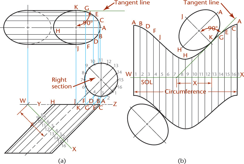
The intersection of a plane and a cylinder is an ellipse whose true size is shown in the auxiliary view of Figure 9.48. The steps for developing a cylinder are as follows:
• Draw elements of the cylinder. It is usually best to divide the base of the cylinder into equal parts, shown in the top view and then projected into the front view.
• In the auxiliary view, the widths BC, DE, and so on, are transferred from the top view at 2–16, 3–15, respectively, and the ellipse is drawn through these points. The major axis AH shows true length in the front view, and the minor axis JK shows true length in the top view. You can use this information to quickly draw the ellipse using CAD.
• Draw the stretchout line for the cylinder. It will be equal to the circumference of the base, whose length is determined by the formula πd.
• Divide the stretchout line into the same number of equal parts as the circumference of the base, and draw an element through each division perpendicular to the line.
• Transfer the true height by projecting it from the front view, as shown in Figure 9.48b.
• Draw a smooth curve through the points A, B, D, and so on.
• Draw the tangent lines and attach the bases as shown in Figure 9.48b.
9.18 Hems and Joints for Sheet Metal and Other Materials
Figure 9.49 shows a wide variety of hems and joints used in fabricating sheet metal parts and other items. Hems are used to eliminate the raw edge as well as to stiffen the material. Joints and seams may be made for sheet metal by bending, welding, riveting, and soldering and for package materials by gluing and stapling.
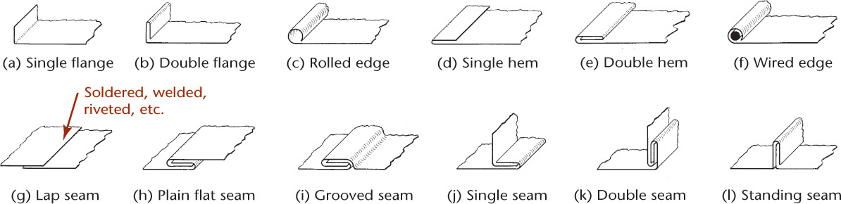
You must add material for hems and joints to the layout or development. The amount you add depends on the thickness of the material and the production equipment. A good place to find more information is from manufacturers. They can be extremely helpful in identifying specifications related to the exact process that will be used to make the part.
9.19 More Examples of Developments and Intersections
Developing a Plane and an Oblique Prism
The intersection of a plane and an oblique prism is shown in Figure 9.50a. Where the plane is normal to the prism formed by plane WX (called a right section) it appears as a regular hexagon, as shown in the auxiliary view labeled “Right section.” The oblique section cut by horizontal plane YZ is shown true size in the top view.
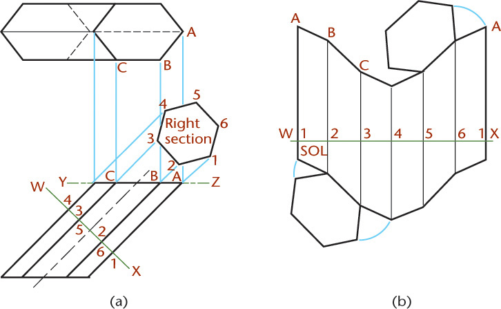
The development for this oblique prism is shown in Figure 9.50b. Use the right section to create stretchout line WX. On the stretchout line, set off the true widths of the faces 1–2, 2–3, and so on, which are shown true size in the auxiliary view. Draw perpendiculars through each division. Transfer the true heights of the respective edges, which are shown true size in the front view. Join the points A, B, C, and so on with straight lines. Finally, attach the bases, which are shown in their true sizes in the top view, along an edge.
Developing a Plane and an Oblique Cylinder
The development of the intersection of a plane and an oblique cylinder is similar to that for a plane and an oblique prism, as shown in Figure 9.51.
Developing a Plane and a Pyramid
The intersection of a plane and a pyramid is a trapezoid, as shown in Figure 9.52.

Developing a Plane and a Cone
The intersection of a plane and a cone is an ellipse, as shown in Figure 9.53. If a series of horizontal cutting planes are passed perpendicular to the axis, each plane will cut a circle from the cone that will show as true size and shape in the top view. Points in which these circles intersect the original cutting plane are points on the ellipse. Because the cutting plane is shown on edge in the front view (Figure 9.53a), all these piercing points can be projected from there to the others, as shown in Figure 9.53b.
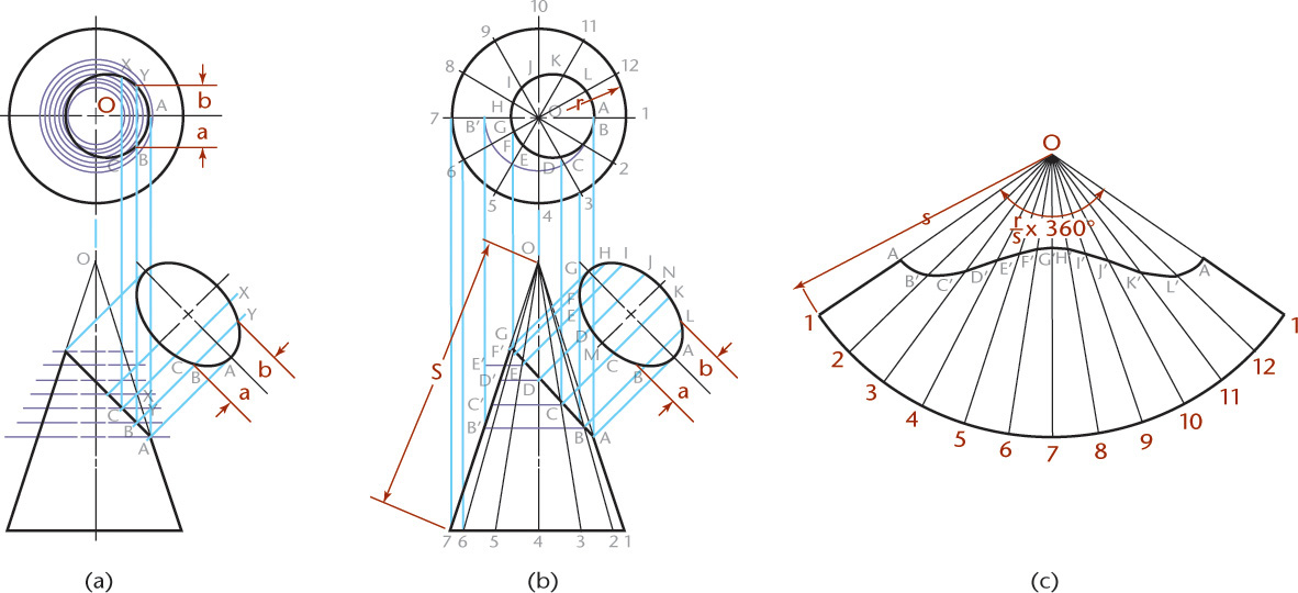
To develop the lateral surface of a cone, think of the cone as a pyramid having an infinite number of edges. The development is similar to that for a pyramid.
Developing a Hood and Flue
The development of a hood and flue is shown in Figure 9.54. Because the hood is a conical surface, it may be developed as shown in Figure 9.53. The two end sections of the elbow are cylindrical surfaces. The two middle sections of the elbow are cylindrical surfaces, but their bases are not perpendicular to the axes, so they will not develop into straight lines.
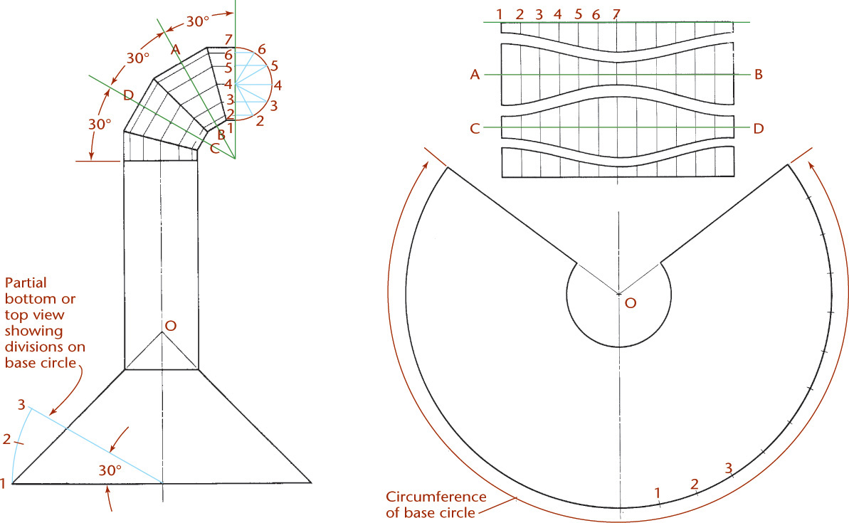
Develop them similar to an oblique cylinder. Make auxiliary planes AB and DC perpendicular to the axes so they cut right sections from the cylinders, which will develop into the straight lines AB and CD in the developments. Arranging the developments as shown allows the elbow to be constructed from a rectangular sheet of metal without wasting material. The patterns are shown in the right top portion of Figure 9.54 as they will be separated after cutting.
9.20 Transition Pieces
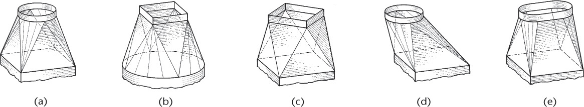
A transition piece is one that connects two different-shaped, different-sized, or skewed position openings. In most cases, transition pieces are composed of plane surfaces and conical surfaces, as shown in Figure 9.55. You will learn about developing conical surfaces by triangulation next. Triangulation can also be used to develop, approximately, certain warped surfaces. Transition pieces are used extensively in air conditioning, heating, ventilating, and similar construction.
Ductwork Parts

Heating, ventilating, and air conditioning (HVAC) systems often use ductwork to transfer air through the system. The standard parts shown above are made of 26 gauge galvanized steel and can be purchased “off the shelf.” When ducts must connect at odd angles to fit into existing spaces, custom designed developments and intersections are required.
9.21 Triangulation
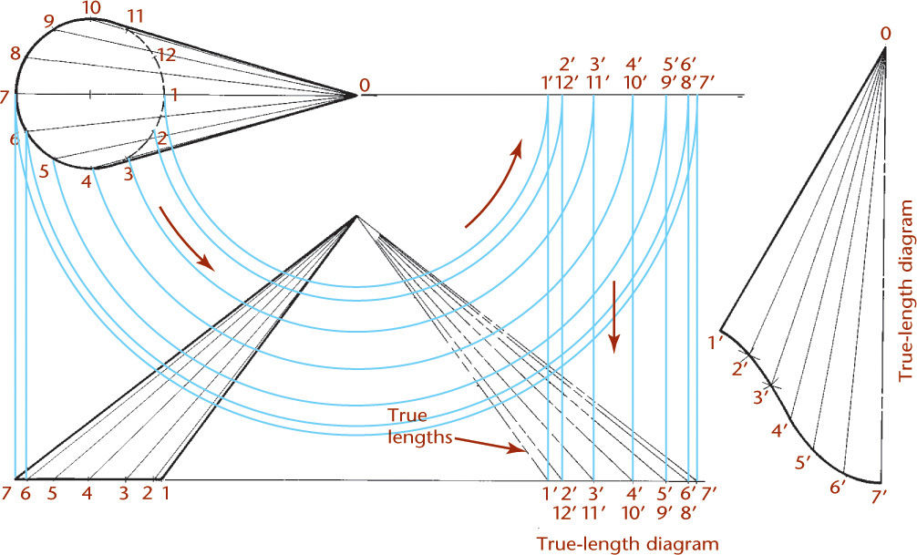
Triangulation is simply a method of dividing a surface into a number of triangles and transferring them to the development. To find the development of an oblique cone by triangulation, divide the base of the cone in the top view into any number of equal parts and draw an element at each division point, as shown in Figure 9.56. Find the true length of each element. If the divisions of the base are comparatively small, the lengths of the chords may be used in the development to represent the lengths of the respective arcs. Because the development is symmetrical, it is necessary to lay out only half the development, as shown at the right side of Figure 9.56.
9.22 Developing a Transition Piece Connecting Rectangular Pipes on the Same Axis
The transition piece can be a frustum of a pyramid that connects rectangular pipes on the same axis, as shown in Figure 9.57. As a check on the development, lines parallel on the surface must also be parallel on the development.

9.23 Developing a Plane and a Sphere
The intersection of a plane and a sphere is a circle. The diameter of the circle depends on where the plane is located. Any circle cut by a plane through the center of the sphere is called a great circle. If a plane passes through the center and is perpendicular to the axis, the resulting great circle is called the equator. If a plane contains the axis, it will cut a great circle called a meridian.
The surface of a sphere is double curved and is not developable, but it may be developed approximately by dividing it into a series of zones and substituting a portion of a right-circular cone for each zone. If the conical surfaces are inscribed within the sphere, the development will be smaller than the spherical surface, but if they are circumscribed about the sphere, the development will be larger. If the conical surfaces are partly inside and partly outside the sphere, the resulting development is closely approximate to the spherical surface. This method of developing a spherical surface, the polyconic method, is shown in Figure 9.58a. It is used on government maps of the United States.
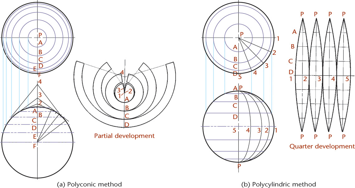
Another method of making an approximate development of the double-curved surface of a sphere is to divide the surface into equal sections with meridian planes and substitute cylindrical surfaces for the spherical sections. The cylindrical surfaces may be inscribed within the sphere, circumscribed about it, or located partly inside and partially outside. This method, the polycylindric method (sometimes called the gore method) is shown in Figure 9.58b.
9.24 Revolution
Revolution, like auxiliary view projection, is a method of determining the true length and true size of inclined and oblique lines and planes. To create the auxiliary view, imagine that the object remains stationary and a new viewing plane is added as shown by the arrow in Figure 9.59a. Surface A shows true size and shape in the auxiliary view.

The same view of the object can be obtained by moving the object with respect to the viewing planes, as shown in Figure 9.59b. Here the object is revolved until surface A appears in its true size and shape in the right-side view. Revolution determines true length and true size without creating another view. Instead, revolution positions an object in space to create standard views that show the true size and shape of the inclined or oblique surface.
Axis of Revolution
Imagine the axis of revolution to be perpendicular to the front plane of projection in Figure 9.59b. The axis of revolution appears as a point in this view. The object revolves but does not change shape in this view. In the adjacent views in which the axis of revolution, if it were drawn, would show as a line in true length, the dimensions of the object that are parallel to the axis of revolution do not change. Other dimensions may appear foreshortened.
Creating a Revolved Drawing
To make a drawing using revolution to show the true size of a surface, use the following procedure:
1. Select the view that has the feature of interest, such as the inclined surface showing as an edge, that you want to revolve to produce a true-size feature in the adjacent view.
2. Select any point at any convenient position on or outside that view about which to draw the view revolved either clockwise or counterclockwise. That point is the end view, or point view, of the axis of revolution.
3. Draw this first view on the plane of projection. This is the only view that remains unchanged in size and shape.
4. Project the other views from this view using standard orthographic projection techniques.
9.25 Primary and Successive Revolutions
The axis of revolution is usually perpendicular to one of the three principal planes of projection. A primary revolution is one in which the object is revolved about an axis perpendicular to the horizontal, frontal, or profile planes of projection. Successive revolutions are drawings that use multiple revolutions of the same object to produce a final revolved drawing with the desired result. Figure 9.60 shows an example. As you can imagine, this is accomplished in one step using CAD.

9.26 True Length of a Line: Revolution Method
A line (edge) appears true length when it is parallel to one of the planes of projection. In Figure 9.61a, line AB (an element of the cone) is oblique to the planes of projection. Line AB appears foreshortened, not true length. If AB is revolved about the axis of the cone until it coincides with either of the contour elements (for example, ABR), it will be shown in its true length in the front view because it will then be parallel to the front plane of projection.
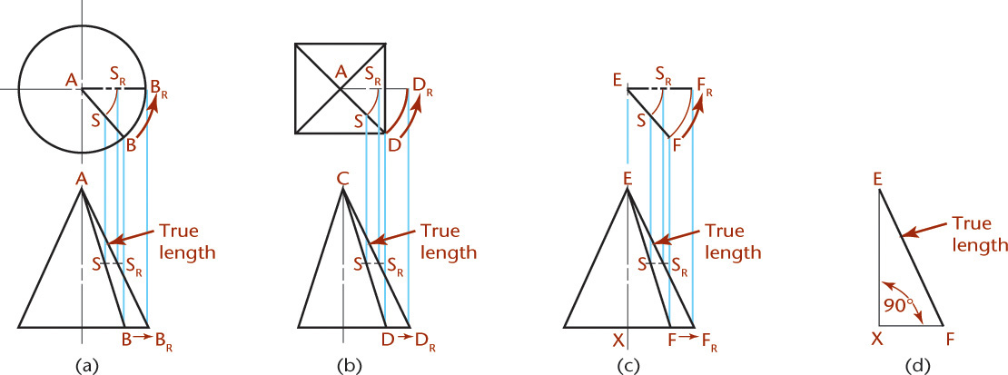
In Figure 9.61b, to show the edge of the pyramid CD true length, it is revolved about the axis of the pyramid until it is parallel to the frontal plane of projection and therefore shows true length in the front view. In Figure 9.61c, line EF is shown true length in the front view because it has been revolved about a vertical axis until it is parallel to the front plane of projection.
The true length of a line may also be found by constructing a right triangle or a true-length diagram (Figure 9.61d) with the base of the triangle equal to the top view of the line, for example, the distance from E to F in the top view in c, drawn as XF in d; and the height of the triangle equal to the projected height, XE, of the line taken from the front view. The hypotenuse of the triangle is equal to the true length of the line.
CAD at Work: Creating Auxiliary Views Using 3D CAD
3D CAD can be used to generate any view in one or two steps, eliminating the need to project auxiliary views and revolve views manually. It is still very important to have a clear understanding of which line of sight will produce a true-size view or a view that shows a true dihedral angle. When a view from a CAD screen is measured or dimensioned, if the surface or angle is not true size, the automatic dimension from the CAD system may be that of the apparent, or projected, distance. Incorrectly dimensioned dihedral angles can be an error in CAD drawings created by inexperienced operators. Drawings should show angles true size where they are dimensioned or note it clearly if this is not the case.
Solid modeling techniques can be used to create accurate intersections between various solids. Some CAD programs have commands for creating transition pieces that blend solids of two differing shapes, for example, a sweep/join operation. Not all CAD software is capable of producing developments (flat patterns) of surfaces. Some surfaces, such as spheres or tori, can only be approximated by a flattened shape.
Views of the Solid Model from Which the Detail Drawings Were Created (Courtesy of Dynojet Research, Inc.)

An auxiliary view is used on the drawing for this sheet metal part so that dimensions are shown where the feature is true size. (Courtesy of Dynojet Research, Inc.)
Double-Curved Surface of Revolution
Extruded Solid
Revolved Solid
Chapter Summary
• An auxiliary view can be used to create a projection that shows the true length of a line or true size of a plane.
• An auxiliary view can be directly produced using CAD if the original object was drawn as a 3D model.
• Folding lines or reference lines represent the edge views of projection planes.
• Points are projected between views parallel to the line of sight and perpendicular to the reference lines or folding lines.
• A common use of auxiliary views is to show dihedral angles true size.
• Curves are projected to auxiliary views by plotting them as points.
• A secondary auxiliary view can be constructed from a previously drawn (primary) auxiliary view.
• The technique for creating the development of a solid is determined by the basic geometric shape. Prisms, pyramids, cylinders, and cones have their own particular development techniques.
• The intersection of two solids is determined by plotting the intersection of each surface and transferring the intersection points to each development.
• Cones and pyramids use radial development. Prisms and cylinders use parallel development.
• Truncated solids, cones, and pyramids are created by developing the whole solid and then plotting the truncated endpoints on each radial element.
• Transition pieces are developed by creating triangular surfaces that approximate the transition from rectangular to circular. The smaller the triangular surfaces, the more accurate the development.
• Revolution moves an object in space, to reveal what would normally be an auxiliary view of the object in a primary view (top, front, right side).
• The main purpose of revolution is to reveal the true length and true size of inclined and oblique lines and planes in a primary view.
Review Questions
1. What is meant by true length? By true size?
2. Why is a true-length line always parallel to an adjacent reference line?
3. If an auxiliary view is drawn from the front view, what other views would show the same depth dimensions?
4. Describe one method for transferring depth between views.
5. What is the difference between a complete auxiliary view and a partial auxiliary view?
6. How many auxiliary views are necessary to draw the true size of an inclined plane? Of an oblique plane?
7. What is the angle between the reference plane line (or folding line) and the direction-of-sight lines?
8. How is the development of a pyramid similar to the development of a cone?
9. When a truncated cone or pyramid is developed, why is the complete solid developed first?
10. What descriptive geometry techniques are used to determine the intersection points between two solids?
11. What is a transition piece?
12. What is a stretchout line?
13. Which parts of a development are true size and true shape?
14. Which building trades use developments and intersections?
15. What is the purpose of revolution?
16. What is the axis of revolution? What determines where the axis is drawn?
17. What are successive revolutions?
Chapter Exercises
Design Project
Exercise 9.1 Breakfast cereal has traditionally been sold in a rectangular box. The packaging must keep the product fresh, be reasonably durable, look attractive on the shelf, and be useful for dispensing the product. Create an innovative new packaging for breakfast cereal that meets these requirements. Make your design a sensible candidate for mass production, striving for a low consumer price and conservation of raw materials. Consider whether to make your packaging reusable, disposable, or refillable. Use the graphic communication skills you have learned so far to represent your design clearly.
Auxiliary View Projects
Exercises 9.2–9.43 are to be drawn with CAD or freehand. If partial auxiliary views are not assigned, the auxiliary views are to be complete views of the entire object, including all necessary hidden lines. Make sure to provide enough space for the auxiliary view.
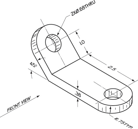
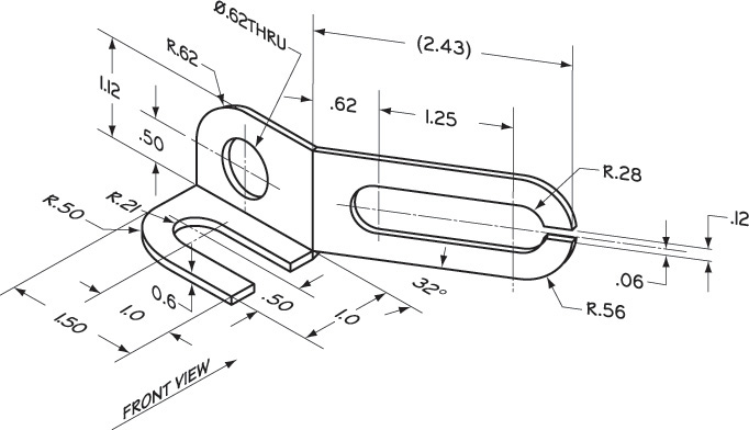
Exercise 9.2 RH Finger. Given: Front and auxiliary views. Required: Complete front, auxiliary, left-side, and top views.
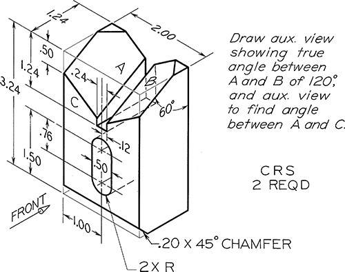
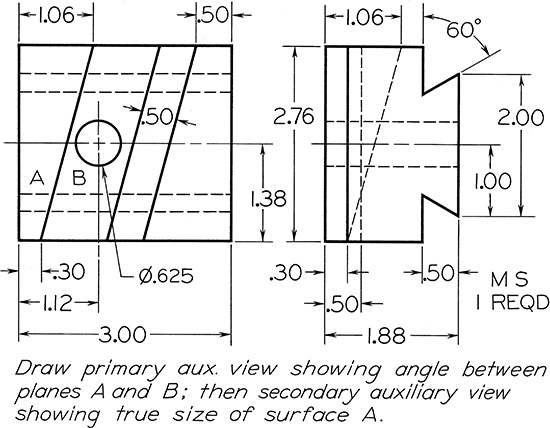
Exercise 9.3 V-Block, Given: Front and auxiliary views. Required: Complete front, top, and auxiliary views.

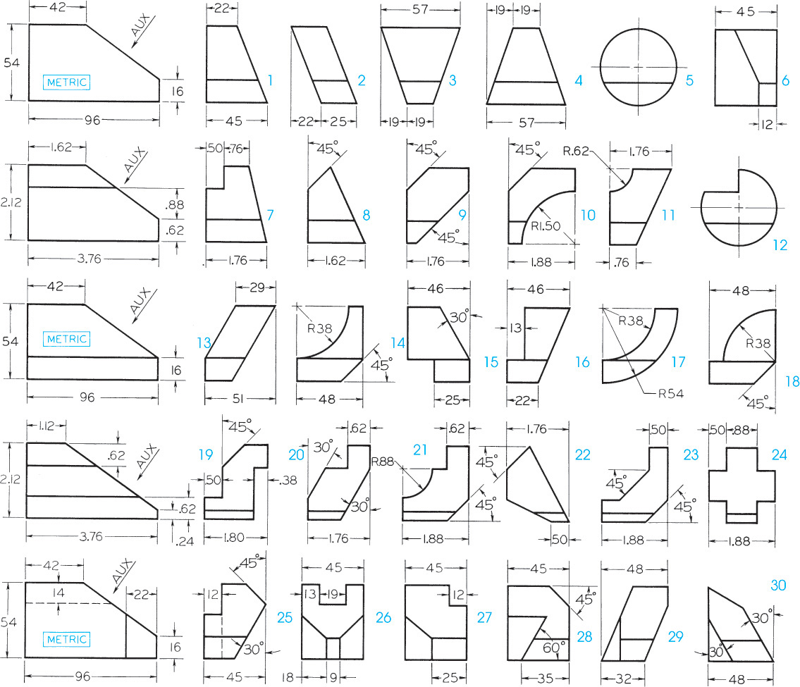
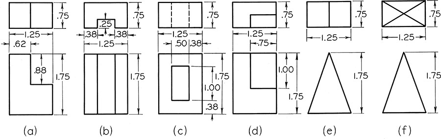
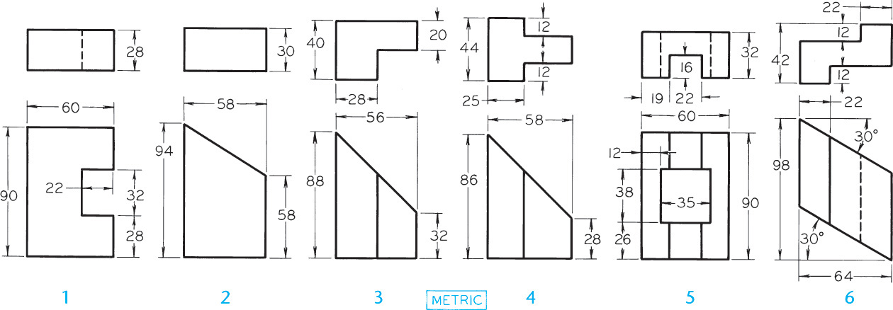
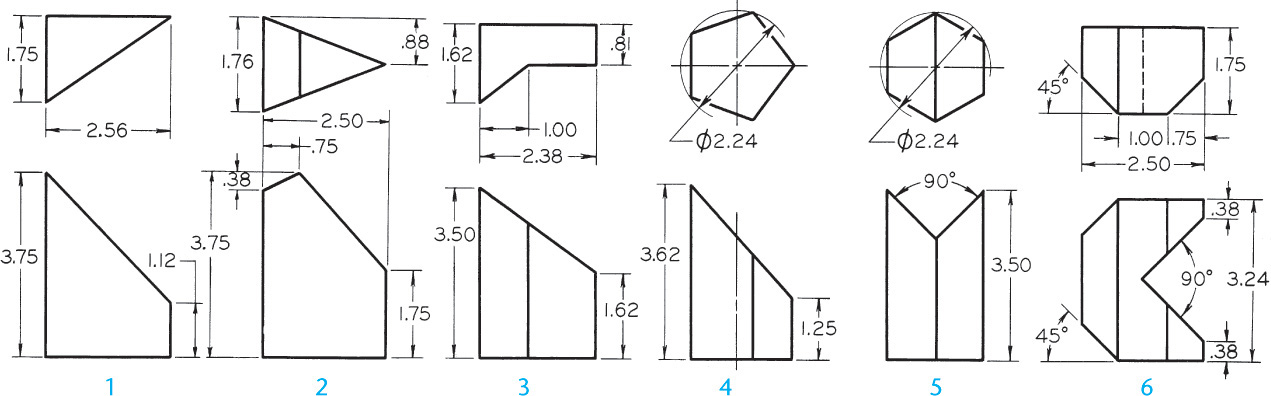
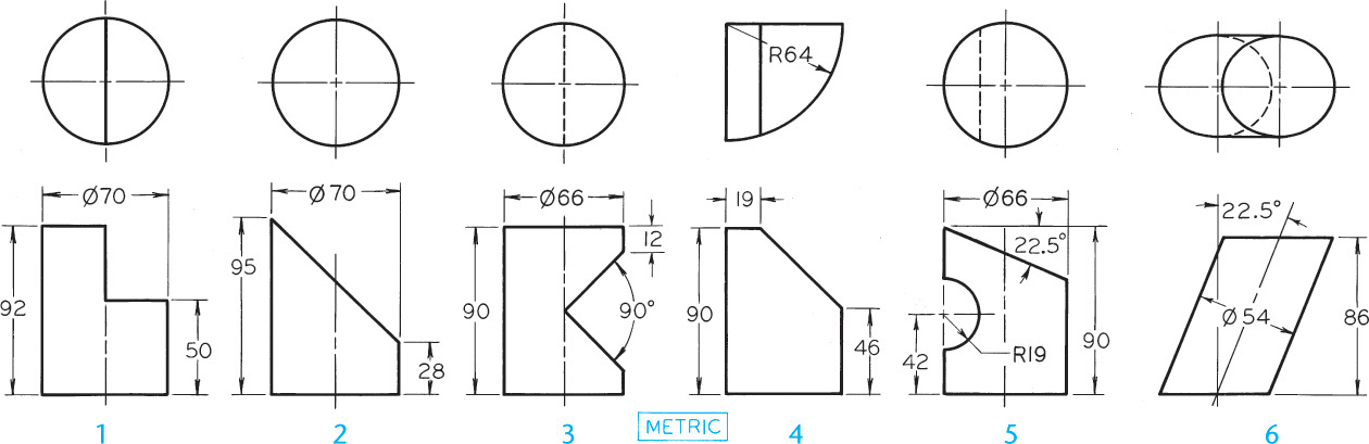
Exercise 9.6 Auxiliary View Problems. Make freehand sketch or instrument drawing of selected problems as assigned. Draw given front and right-side views, and add incomplete auxiliary view, including all hidden lines. If assigned, design your own right-side view consistent with given front view, then add complete auxiliary view.
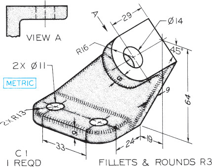
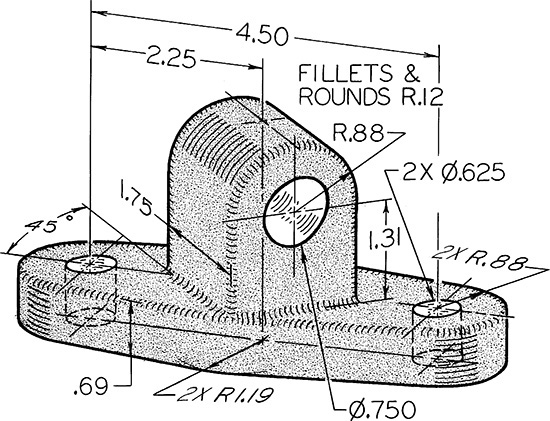
Exercise 9.7 Anchor Bracket. Draw necessary views or partial views.*
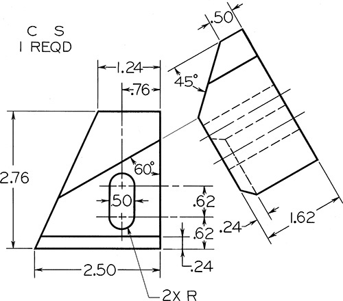
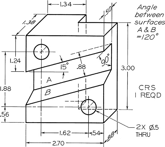
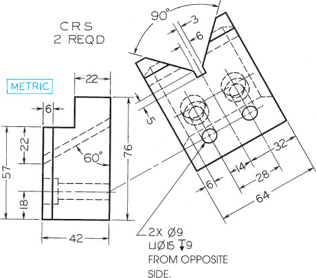
Exercise 9.8 Centering Block. Draw complete front, top, and right-side views, plus indicated auxiliary views.*
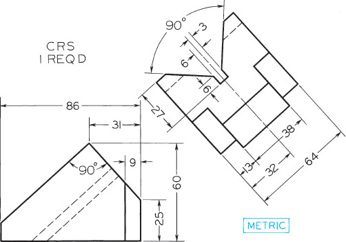
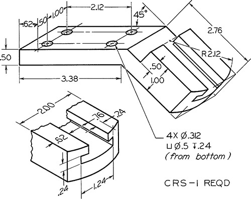
Exercise 9.9 Clamp Slide. Draw necessary views completely.*
Exercise 9.10 Guide Block. Given: Right-side and auxiliary views. Required: Right-side, auxiliary, plus front and top views—complete.*

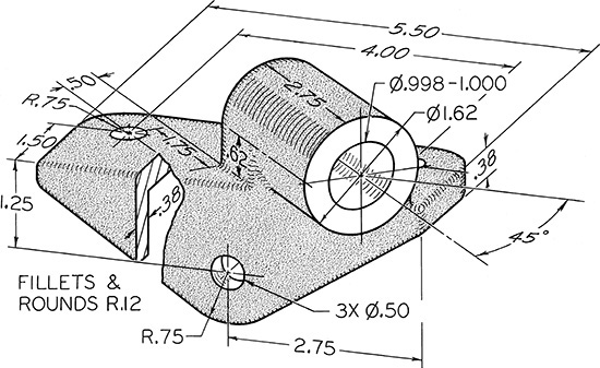
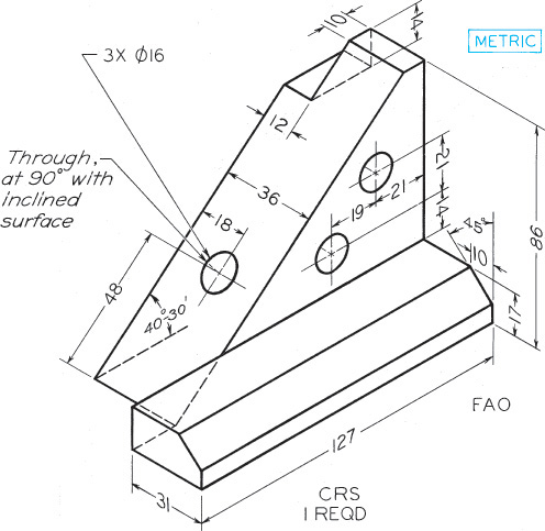
Exercise 9.11 Angle Bearing. Draw necessary views, including complete auxiliary view.*
Exercise 9.12 Guide Bracket. Draw necessary views or partial views.*
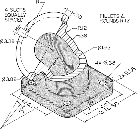
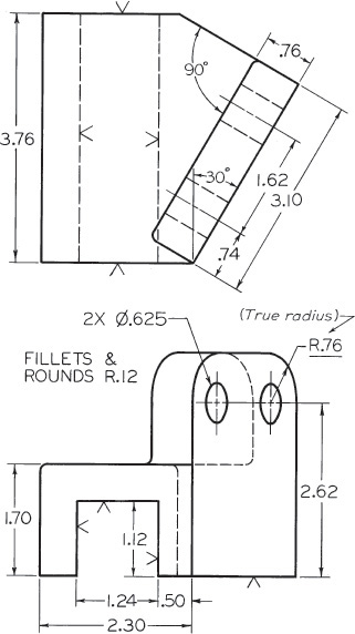
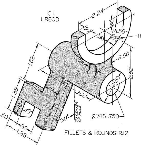
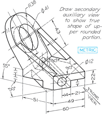
Exercise 9.13 Rod Guide. Draw necessary views, including complete auxiliary view showing true shape of upper rounded portion.*
Exercise 9.14 Brace Anchor. Draw necessary views, including partial auxiliary view showing true shape of cylindrical portion.*
Exercise 9.15 45° Elbow. Draw necessary views, including a broken section and two half views of flanges.*

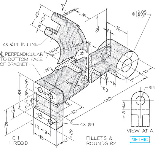
Exercise 9.16 Control Bracket. Draw necessary views, including partial auxiliary views and regular views.*

Exercise 9.17 Angle Guide. Draw necessary views, including a partial auxiliary view of cylindrical recess.*
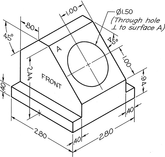
Exercise 9.18 Holder Block. Draw front and right-side views (2.80″ apart) and complete auxiliary view of entire object showing true shape of surface A and all hidden lines.*
Exercise 9.19 Adjuster Block. Draw necessary views, including complete auxiliary view showing true shape of inclined surface.*
Exercise 9.20 Guide Bearing. Draw necessary views and partial views, including two partial auxiliary views.*

Exercise 9.21 Tool Holder Slide. Draw given views, and add complete auxiliary view showing true curvature of slot on bottom.*
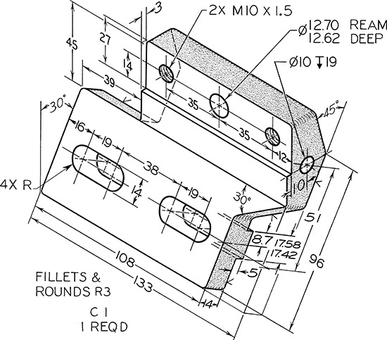
Exercise 9.22 Drill Press Bracket. Draw given views and add complete auxiliary views showing true shape of inclined face.*

Exercise 9.23 Brake Control Lever. Draw necessary views and partial views.*
Exercise 9.24 Shifter Fork. Draw necessary views, including partial auxiliary view showing true shape of inclined arm.*
Exercise 9.25 Cam Bracket. Draw necessary views or partial views as needed.*
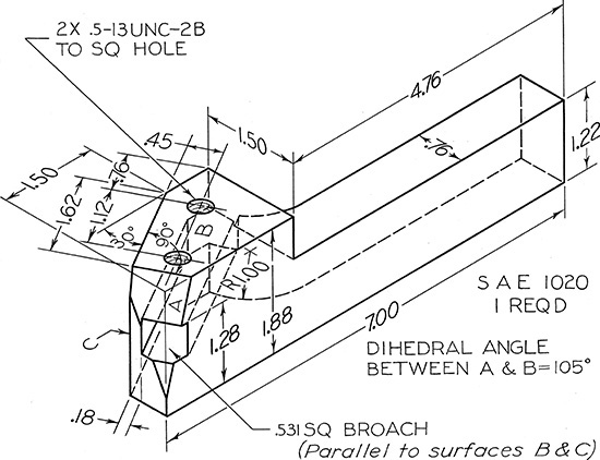
Exercise 9.26 RH Tool Holder. Draw necessary views, including partial auxiliary views showing 105° angle and square hole true size.*
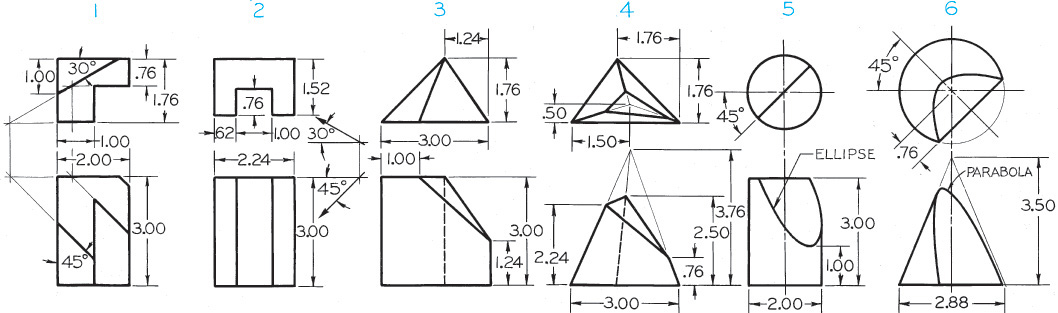
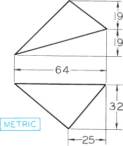
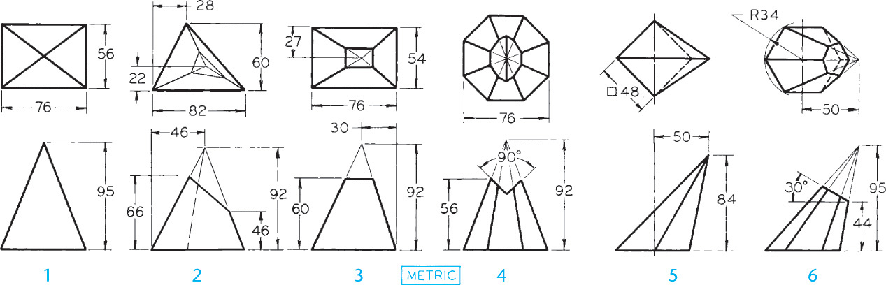
Exercise 9.27 Draw complete secondary auxiliary views, showing the true sizes of the inclined surfaces (except for Problem 2). In Problem 2 draw secondary auxiliary view as seen in the direction of the arrow given in the problem.*
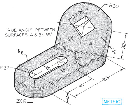
Exercise 9.28 Control Bracket. Draw necessary views including primary and secondary auxiliary views so that the latter shows true shape of oblique surface A.*
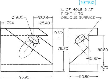
Exercise 9.29 Holder Block. Draw given views and primary and secondary auxiliary views so that the latter shows true shape of oblique surface.*
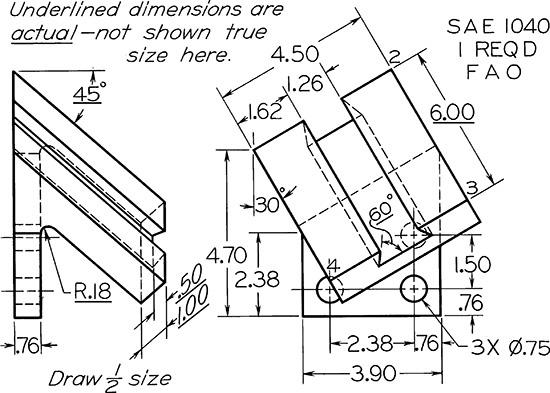
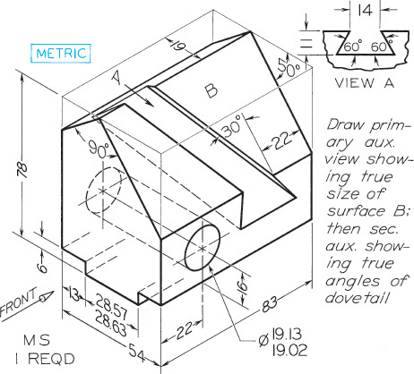
Exercise 9.30 Dovetail Slide. Draw complete given views and auxiliary views, including view showing true size of surface 1–2–3–4.*
Exercise 9.31 Dovetail Guide. Draw given views plus complete auxiliary views as indicated.*
Exercise 9.32 Adjustable Stop. Draw complete front and auxiliary views plus partial right-side view. Show all hidden lines.*
Exercise 9.33 Tool Holder. Draw complete front view, and primary and secondary auxiliary views as indicated.*
Exercise 9.34 Mounting Clip. Draw all required views. Include at least one auxiliary view.*

Exercise 9.35 Box Tool Holder for Turret Lathe. Given: Front and right-side views. Required: Front and left-side views, and complete auxiliary view as indicated by arrow.*

Exercise 9.36 Pointing Tool Holder for Automatic Screw Machine. Given: Front and right-side views. Required: Front view and three partial auxiliary views.*
*If dimensions are required, study Chapter 11. Use metric or decimal-inch dimensions if assigned.
Revolution Exercises
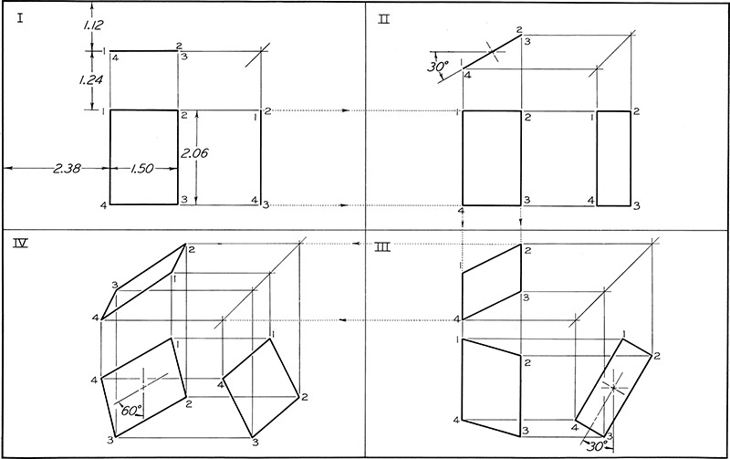
Exercise 9.37 Divide the working area into four equal parts, as shown. Draw given views of the rectangle, and then the primary revolution in space II, followed by successive revolutions in spaces III and IV. Number points as shown. Omit dimensions. Use Form 3 title box.
Exercise 9.38 Divide the working area into four equal parts, as shown. Draw given views of prism as shown in space I, then draw three views of the revolved prism in each succeeding space, as indicated. Number all corners. Omit dimensions. Use Form 3 title box.
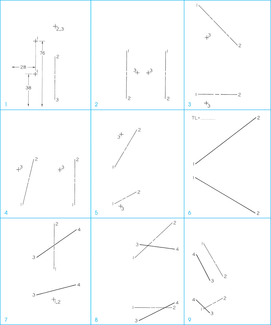
Exercise 9.39 Divide the working area into four equal areas for four problems per sheet to be assigned by the instructor. Data for the layout of each problem are given by a coordinate system in metric dimensions. For example, in Problem 1, point 1 is located by the scale coordinates (28 mm, 38 mm, 76 mm). The first coordinate locates the front view of the point from the left edge of the problem area. The second one locates the front view of the point from the bottom edge of the problem area. The third one locates either the top view of the point from the bottom edge of the problem area or the side view of the point from the left edge of the problem area. Inspection of the given problem layout will determine which application to use.
1. Revolve clockwise point 1(28, 38, 76) through 210° about axis 2(51, 58, 94)–3(51, 8, 94).
2. Revolve point 3(41, 38, 53) about axis 1(28, 64, 74)–2(28, 8, 74) until point 3 is at the farthest distance behind the axis.
3. Revolve point 3(20, 8, 84) about axis 1(10, 18, 122)–2(56, 18, 76) through 210° and to the rear of line 1–2.
4. Revolve point 3(5, 53, 53) about axis 1(10, 13, 71)–2(23, 66, 71) to its extreme position to the left in the front view.
5. Revolve point 3(15, 8, 99) about axis 1(8, 10, 61)–2(33, 25, 104) through 180°.
6. By revolution find the true length of line 1(8, 48, 64)–2(79, 8, 119). Scale: 1:100.
7. Revolve line 3(30, 38, 81)–4(76, 51, 114) about axis 1(51, 33, 69)–2(51, 33, 122) until line 3–4 is shown true length and below axis 1–2.
8. Revolve line 3(53, 8, 97)–4(94, 28, 91) about axis 1(48, 23, 81)–2(91, 23, 122) until line 3–4 is in true length and above the axis.
9. Revolve line 3(28, 15, 99)–4(13, 30, 84) about axis 1(20, 20, 97)–2(43, 33, 58) until line 3–4 is level above the axis.
Exercise 9.40 Divide your sheet into four equal parts. In the upper left space draw the original drawing. In the upper right draw a simple revolution, and in the lower two spaces draw successive revolutions. Alternative assignment: Divide into two equal spaces. In the left space draw the original views. In the right space draw a simple revolution.

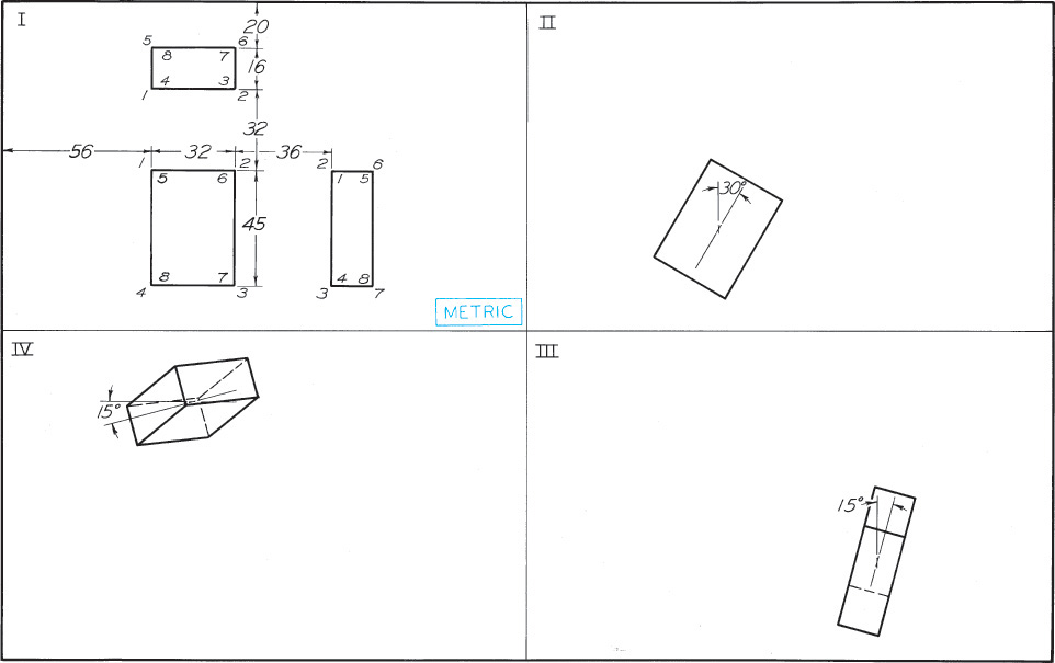
Exercise 9.41 Draw three views of the blocks but revolved 30° clockwise about an axis perpendicular to the top plane of projection. Do not change the relative positions of the blocks.
Exercise 9.42 Draw three views of a right prism 38 mm high that has as its lower base the triangle shown above.

Exercise 9.43 Draw three views of a right pyramid 51 mm high, having as its lower base the parallelogram shown above.
Exercise 9.45 Draw the given views and develop the lateral surface.
Exercise 9.46 Draw the given views and develop the lateral surface.
Exercise 9.47 Draw the given views and develop the lateral surface (Layout A3–3 or B–3).

Exercise 9.48 Draw the given views and develop the lateral surface (Layout A3–3 or B–3).
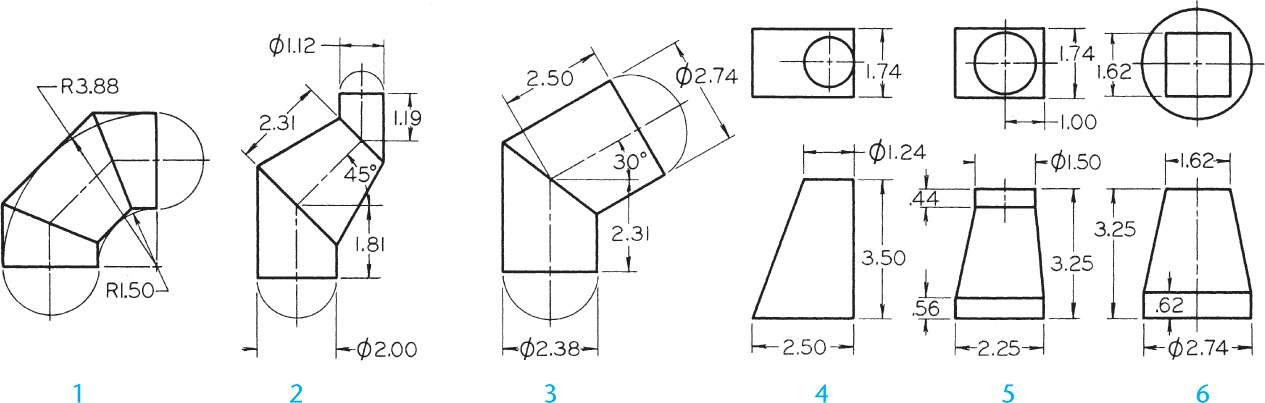
Exercise 9.49 Draw the given views of the forms and develop the lateral surface (Layout A3–3 or B–3).
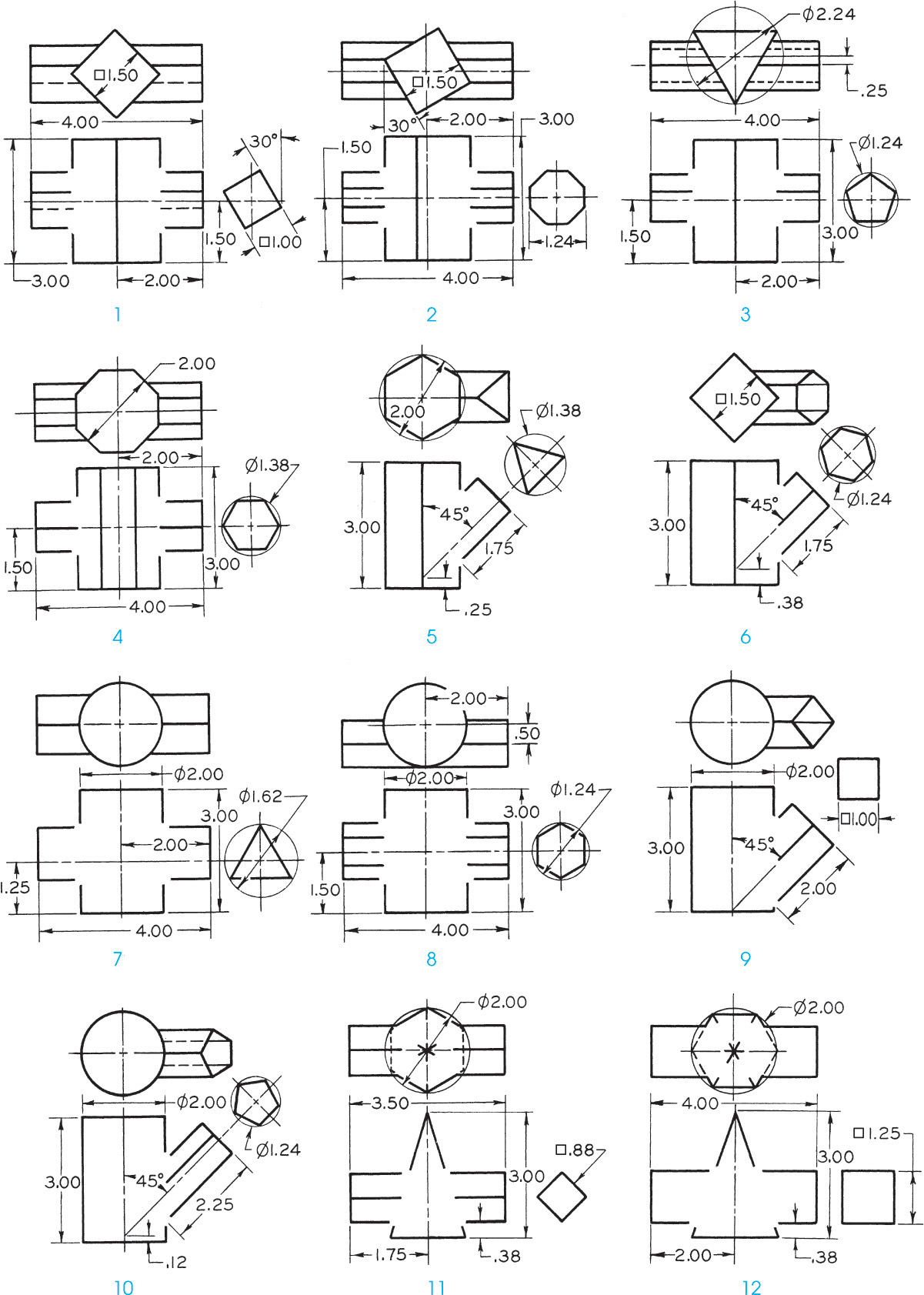
Exercise 9.50 Draw the given views of assigned form and complete the intersection, then develop the lateral surfaces.

Exercise 9.51 Draw the given views of assigned form and complete the intersection, then develop the lateral surfaces.