
Chapter 15. Architectural Materials
UE4’s Material system is like a good video game: simple to learn but takes a lifetime to master. Making great UE4 Materials for production isn’t only about artistic quality, but about creating reusable Materials, getting the best-performance possible, and learning new techniques that aren’t used in raytracing renders such as Parallax Occlusion Mapping.
Materials and lighting work hand-in-hand to create a rich, realistic environment for your Player. You can achieve amazing results using simple Materials. Now that your lighting is started, you can begin getting some Materials into your scene and making it come to life with color, reflection, and surface detail and variation.
Getting great-looking Materials in UE4 is straightforward because using PBR (physically based rendering) is straightforward. By defining the Base Color, Roughness, Metallic, and Normal parameters, the Engine does the hard work and creates a Material that follows the rules of physics to create amazingly rich surfaces to populate your scenes.
Be sure to review Chapter 5, “Materials” for coverage of the basics of Material creation in UE4, especially the creation of Material Instances. You will rely heavily on them to quickly make a large library of Materials and apply them to your scene.
What Is a Master Material?
As discussed in Chapter 5, you could create a unique Material for each surface as you might in a traditional 3D renderer. This could be very time consuming, especially when you start adding more functionality into your Materials.
Instead, you will use Material Parameters to create a single Material and then several Material Instances of that Material, assigning Textures and overriding properties to create almost every Material used in your scene.
This single Material is often referred to as a Master Material. A Master Material isn't a specific Asset type in Unreal Engine. Rather, it is a concept. Any Material can be a Master Material if you author it with Material Parameters. Material Parameters expose variables to Material Instances that can be changed on the fly both in the Editor and at runtime using Blueprints.
Thanks to the simplicity of physically based rendering, your Material network does not need to be excessively complex. Using only Color, Normal, Metallic, and Roughness Textures along with the occasional height map, you can define almost any surface.
You can even create typically difficult-to-achieve surfaces like metal, glass, and architectural wall coverings with minimal effort and without resorting to authoring complex custom Materials. You can follow along, building your own Material, or you can download the complete project files at www.TomShannon3D.com/UnrealForViz.
Material Network Overview
Figure 15.1 shows a Master Material. At first glance, it might look complicated, but it's really straightforward.
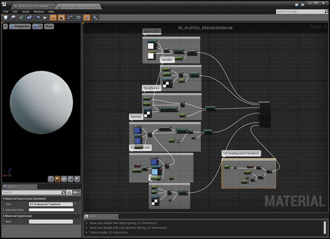
Figure 15.1 Complete M_ArchViz_MasterMaterial shader graph showing a single Material that can be used for almost every Material in the scene via the use of Material Instances
Materials are like Blueprints and use a node-based graph to help you visualize what are essentially programming concepts. Nodes are connected to other nodes and data flows from left to right, finally terminating in one of the Material’s various attributes such as Base Color or Roughness.
You’ll take the concepts covered in Chapter 5 and expand upon them, adding some new node types that allow greater flexibility in the Material instances or that provide advanced rendering features such as Parallax Occlusion Mapping.
Parameter Nodes
There are special kinds of Material Expression Nodes you can place in your Material Graph, called Parameters. These nodes let you expose certain aspects of your Material that can be dynamically modified using Material Instance assets or at runtime with Blueprints.
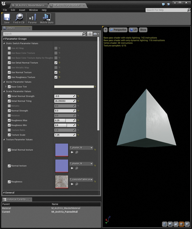
Parameters authored in a Material are exposed as editable Properties in Material Instances that derive from that Material. In the Material Instance Editor (see Figure 15.2), you must click the checkbox to the left of the property you want to override before modifying the value. To return the value to default, click the small yellow arrow next to a modified property. You can also turn off the checkbox to cancel the override.
Creating the Master Material
As shown in Figure 15.1, there’s a lot that needs to be set up to create a good Master Material. Each Material input (Base Color, Metallic, Roughness, and Normal) has a series of nodes connected to it that enable you to create endless variations to your Materials with Material Instances.
Let’s go through each input and see how it’s set up. You can follow along, making your own Master Material, or refer to the files at www.TomShannon3D.com/UnrealForViz.
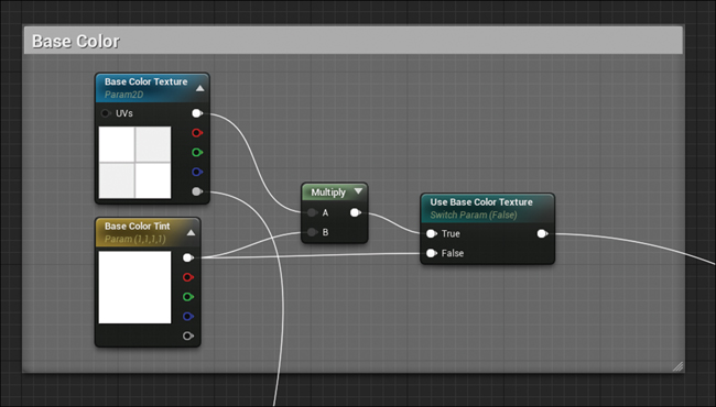
Base Color
Figure 15.3 shows a Texture Parameter 2D called Base Color Texture that is multiplied by a Vector Parameter called Base Color Tint. Remember that Materials are Math and that Colors are treated as RGB Vectors. This means you can perform all manner of vector math operations to the colors in textures, allowing you to perform adjustments on the fly.
Adding Parameters
To place a Texture Parameter node, simply use the palette or the right-click menu and select Texture Parameter from the list. You then want to name the Parameter something meaningful. Parameters can have spaces and punctuation in their names making them easier to read, but it might make those variables more difficult to access through code.
Parameter nodes can be renamed and modified using the Details panel. Using the Details panel, you also need to define the default Texture asset to be used for this node. You can either click on the thumbnail to bring up a browser, or drag and drop a Texture from the Content Browser onto the node’s properties1.
1. You can also create Texture 2D node in your graph by dragging a Texture from the Content Browser into the Material Graph. This will not be a Parameter node, but can easily be converted into one by right-clicking the Texture 2D node and selecting Convert to Parameter from the context menu.
Place a Vector Parameter in the same manner, again giving it a meaningful name. A Vector Parameter can be edited by either modifying the RGBA values in the Details panel, or by double-clicking on the color swatch in the node. This brings up a color picker, which is a lot easier to use.
Multiplying Colors
Add a Multiply node using the Palette, or the right-click menu and connect the Base Color Texture output to the A input and the Base Color Tint output to the B input.
The Multiply node multiplies each channel of input A with input B, and returns the result. Multiplying a vector (the base Color Texture’s RGB output node) with another vector (BaseColor Tint’s RGB output node) means each of the individual RGB channels are multiplied by one another (RedA x RedB, BlueA x BlueB, GreenA x GreenB). You can also multiply one data type by another, such as a Vector and a Scalar (float)—in this case, it would multiply each channel of the Vector by the value of the Scalar.
Using a Multiply node for colors is the same as a Multiply blend mode you might be familiar with in many applications. Black (0,0,0) completely colors your Base Color black, because anything multiplied by 0 is 0. Pure white (1,1,1) does not modify the incoming value at all. Of course, you can choose a color instead, tinting the pixels. You can also go past 1 (or below 0) in your Vector Parameter, acting as a brightness adjustment for the Texture. This can sometimes cause non-physically accurate results, so take care when overdriving your inputs this way.
Static Switch Parameters
The Static Switch Parameter node displays a Boolean checkbox in Material Instances. If the parameter is set to true (either in the Material or Material Instances that derive from it), the Material will evaluate the code path connected to the True input; and if false, to the False pin.
Changing the value of the Static Switch may also update the Material Instance’s interface. Parameters that are not being called, such as Base Color Texture, will not be shown the Material Instance Editor, resulting in less clutter and avoiding presenting the user with options that don’t do anything.
Connect result of the Multiply node to the True input and the Output of the Base Color Tint Parameter to the False input of the Static Switch Parameter.
In this case, if Use Base Color Texture is false, the Material will use Base Color Tint to define the Base Color, bypassing the Texture and Multiply nodes. This saves on Texture reads and Shader calculations, making for a more performant Material.
Metallic
The Metallic input channel is one of the least used attributes and can usually just be set to 0 or 1 via the Metallic Scalar Parameter (see Figure 15.4).
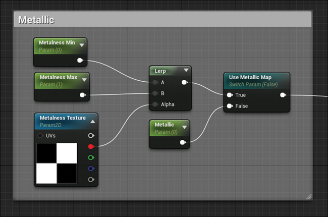
However, sometimes you might want to use a Texture as a mask to define areas of a model that are metallic and those that are not; for example, a wood texture with nails or screws visible, or a material representing chipped paint, revealing a metallic surface underneath.
To allow for this, create a Texture Parameter 2D node called Metalness Texture.
Place a Linear Interpolate (or Lerp, as it is more widely known as) node to allow you remap values to other values using simple Min and Max Parameters for each. The Alpha input acts as a percentage weight between the A and B inputs, 0.0 being fully the value of the A input and 1.0 being fully the value of the B input. By modulating these values, you can easily adjust the surfaces of your scene interactively and predictably.
Create two Scalar Parameters called Metalness Min and Metalness Max, and connect them to the A and B inputs of the Lerp node. Set the Default Value of Metalness Max to 1.0 using the details panel. Adjusting the Metalness Min and Metalness Max settings lets you tweak the mask values easily without having to modify the Texture (see Chapter 5 for more information).
To allow the Texture to be turned off completely, place another Static Switch Parameter on the Graph and name it. If this Parameter is set to true, the Red channel of the Metalness Texture is sampled and then modified using the Lerp node. Because the Metallic input only requires a grayscale or scalar input (0-1), only the Red channel of the texture is used as the alpha of the Lerp node2.
2. Using only a single channel from a Texture allows advanced users to utilize each channel of an RGB texture to store a different grayscale image.
If the Use Metallic Map Parameter is set to false, it will use a Metallic Scalar Parameter that is set to 0.0 and wired to the False input.
Roughness
The Roughness channel is probably the most important channel besides Base Color (sometimes more so as discussed in Chapter 5). However, as you can see in Figure 15.5, it’s set up much like other channels, with the Use Roughness Texture Static Switch Parameter toggling between the Texture-based roughness and the Roughness Scalar Parameter.
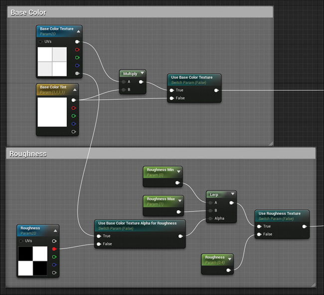
Figure 15.5 Roughness node graph also showing the Base Color so you can see how the Alpha of the Base Color Texture can be used as your Roughness map
Build your Material Graph as shown in Figure 15.5. Pay attention to the default values of each Parameter node as you prepare building your network.
The Use Base Color Texture Alpha for Roughness Static Switch Parameter allows either the Alpha channel of the Base Color Texture to be used as the Roughness mask or the Red channel of a Roughness Texture Parameter. Using the Alpha of the Base Color Texture is a common workflow, and many Assets available in the Marketplace and freely in the community are authored to use this method for defining the Roughness in Materials.
Another Static Switch Parameter called Use Roughness Texture allows you to switch between a single Roughness scalar value connected to the False input and the Texture-based pathway that flows from the True input. If Use Roughness Texture is set to true, the texture data returned by the Use Base Color Texture Alpha for Roughness Parameter is modulated using a Lerp node and the Roughness Min and Roughness Max Scalar Parameters.
Normal
The Normal channel is likely the least familiar to most visualization artists. Most 3D applications rely on bump and height maps to define surface microvariation. Real-time applications, UE4 included, use normal maps instead, because they are faster to calculate than a bump map, and they can define surface curvature, making them higher quality than bump maps.
You create Normal Texture Parameter nodes much like any other Texture Parameter. However, you must set the Sampler Type to Normal in the node’s Details panel. This is done automatically if you assign a normal map texture to the node’s Texture property.
To control the normal map’s intensity, Lerp between the Normal Texture’s value connected to the A input and a Constant Vector value of 0,0,1 (the value for an unmodified normal) connected to the B input (see Figure 15.6).
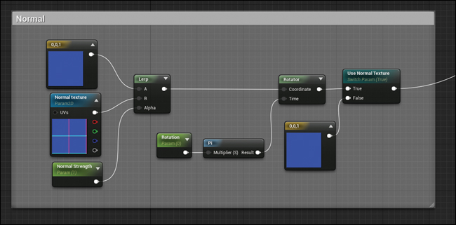
To account for rotation, normal maps need to be modified to maintain the correct vector math. Use a Rotator node to rotate the data returned by the Lerp. A Scalar Parameter called Rotation is multiplied by Pi and used as the Time input on the Rotator node tied to the UV and Texture Transforms (explained later). To be clear, you are rotating the value of the normal map, rather than the Texture.
Vector math like this is the lifeblood of 3D applications. Everything from movement in 3D space to the colors of Materials are vectors. Learning vector math is one of the best things you can do as an artist looking to increase your capabilities and skills in every part of UE4.
Ambient Occlusion
The optional Ambient Occlusion (AO) map is for manually defining the microsurface ambient occlusion of a Material (see Figure 15.7). If this input is not defined, UE4 will generate this data dynamically using the normal map, but sometimes this isn’t entirely accurate or what the artist intends. The AO channel is most often used when Texture sets have been baked using a program like Substance designer or XNormal and can be left off in most cases.
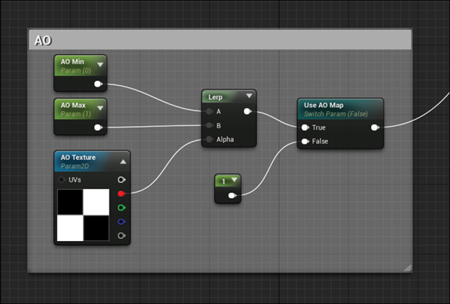
Figure 15.7 Ambient Occlusion node graph, typically only used in special circumstances when UE4’s Materials need some help
Set up your graph as shown in Figure 15.7. Like the roughness and Metallic inputs, AO only requires a scalar or grayscale input; therefore, only the Red channel of the AO Texture Parameter is used.
The Use AO Map Static Switch Parameter allows Material Instances to skip using the AO map altogether. Unlike some of the other Switch Parameters where the False input is fed a Scalar Parameter, here we will simply assign a Constant node and set it to 1.0. Unlike Scalar Parameters, Constant variables cannot be changed at runtime.
Texture Scaling and Transform
Adjusting the scale and positions of Textures is essential for getting the look of your Materials right. In UE4, rather than adjusting the scale of the Texture as you might in a 3D application, you modify the surface’s UV coordinates in real time using the shader network (see Figure 15.8).
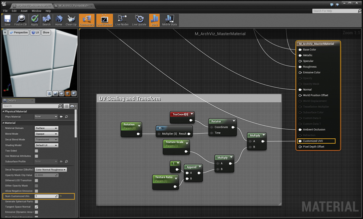
Start by adding a Texture Coordinate node (titled TexCoord[0] in Figure 15.8). This node returns the UV coordinates of a specific UV channel.
You then modify the UV coordinate it returns by first rotating it around the center of the Texture using the Rotator. This node is driven by wiring the Rotation Scalar Parameter into the Time input3. To make the Rotation Parameter easier to author in Material Instances, it is multiplied by pi, converting Rotation into a 0.0–1.0 range with 0.5 being 180 degrees.
3. The Rotation Parameter is used multiple times in this shader. If parameters have the same parameter name, changes to the single value affects all nodes with that name.
To scale the coordinates, therefore scaling/tiling the Texture, they must be multiplied. The Texture Scale Parameter handles this task. Values over 1 cause the Texture to tile more, whereas values below 0 cause the Texture to appear larger, tiling less.
The Texture Ratio Parameter allows the Texture to be non-uniformly scaled. The Append node creates a Vector2 value (a value with two floats; in this case the U and V channels like 0,0 or 0.2,1.0) with a Constant of 1.0 as the first value and the Texture Ratio as the second. This returns a vector2D value like 1.0, 0.5, which is then multiplied by the Texture Scale Parameter, the result of that then being multiplied by the rotated coordinates.
The result of all this is a modified UV coordinate that you then wire into the Customized UV0 attribute of the Material. This input is not exposed by default. To enable this option, you must first set the Num Customized UVs property on the Material. Setting it to 1 or greater adds the Customized UV input nodes to the Material.
Custom UVs allow you to avoid having to wire the transformed UV coordinates into each and every UV input on all the Texture nodes in your Material. Instead, the data fed to the Custom UV inputs modifies the UV channel’s coordinates. Now, any Texture that’s set to use the UV coordinate channel will be provided these modified UV values.
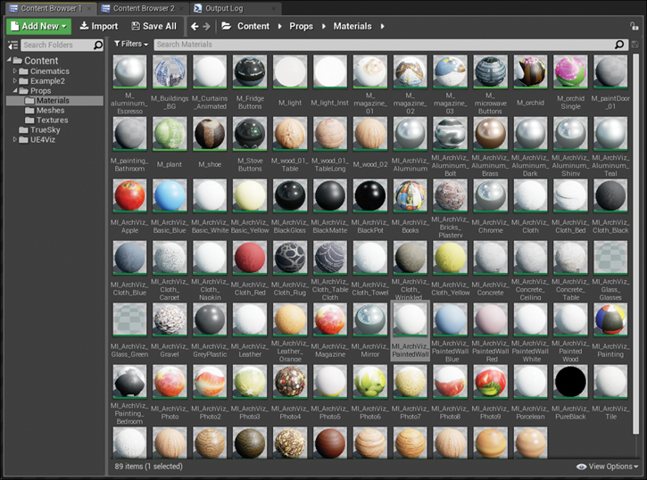
Creating Material Instances
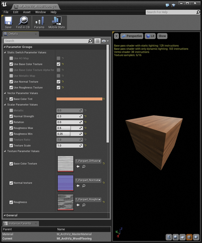
Figure 15.9 shows many of the Material Instances used in the scene. Almost all of these Instances are based on the single Master Material detailed earlier. Each Material Instance has had new Textures applied and Parameters adjusted, creating the diverse Material Library available here.
Painted Walls
Many different colors of paint are required for this scene. For each is a Material Instance is created, each a different color defined by changing the Base Color Tint Parameter. However, as you can see from Figure 15.10, I also had to set a lot of Parameters to get the right look for this Material Instance: I had to assign Textures, toggle Static Switch Parameters, and modify scalar values, resulting in a rich-looking wall surface.
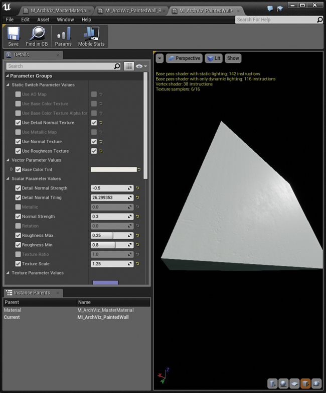
Figure 15.10 Painted Wall Material Instance with many Parameters modified to adjust the Material exactly to the desired look
All the different painted wall color variations derive from the same Master Material; however, they are parented to another Material Instance instead of directly to the Master Material (see Figure 15.11). This demonstrates one of the most powerful features of Material Instances: the ability to base Material Instances on other Material Instances.
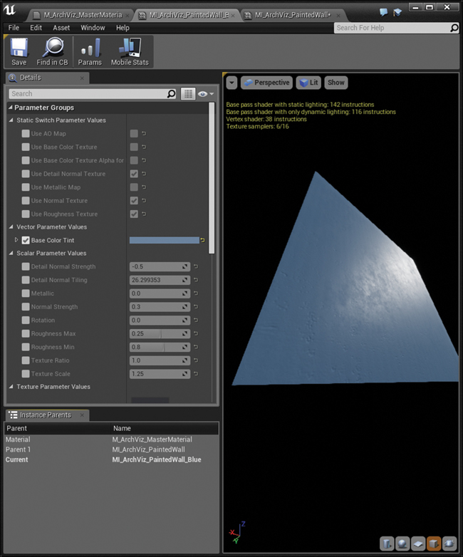
Figure 15.11 M_ArchViz_PaintedWall _Blue Material Instance derived from another Material Instance: M_ArchViz_PaintedWall
Creating Material Instances from other Material Instances enables you to set up a single Master Material Instance that when modified, the changes cascade down to all the Material Instances that inherit from it.
This lets you create endless variations on a theme and then adjust them all on the fly without having to modify each one individually. Properties that have been overridden in child Material Instances, like Base Color Tint, won’t be changed by changes to the parent, preserving any modifications you’ve made.
Floors
The floors can be some of the simplest Material Instances, but they’re some of the most important. Getting the reflections and details right on floors in visualizations is important, because it provides contact with the furniture, walls, and other Props (see Figure 15.12). The floor comprises a huge percentage of the typical view, so tweaking and refining your floor Materials is well worth the effort.
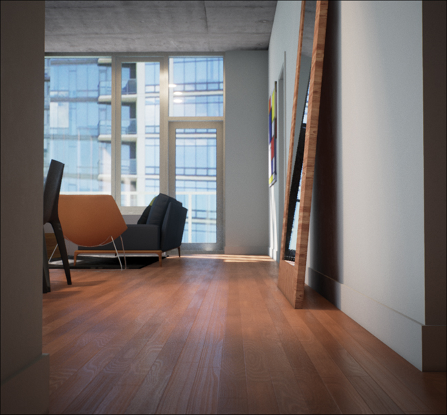
Figure 15.12 Floor Material Instance relies on a good normal map and Roughness map that’s been heavily tweaked using the Material Instance Parameters
Using a Texture sample of the flooring to be used provided by the client, I generated the Normal, Base Color, and Roughness Texture maps using Substance Bitmap 2 Material (B2M). This commercial application is one of many available that use image processing techniques on a simple image and attempt to generate PBR Textures to be used in game engines like UE4.
As you can see from Figure 15.13, while the Textures created with B2M were good, they still needed a lot of tweaking to get right. This is why setting up Parameters in your Materials to allow adjustments is so important. Without them, you would need to modify your Texture Assets, reimporting them each time to see the changes. This way you can see in-context what your Material should look like.
Advanced Materials
Although the Master Material is fantastic at dealing with most opaque surfaces, it can't handle everything. Materials like glass and brick need more specific Materials to look their best and take advantage of UE4’s rendering capabilities.
Parallax Occlusion Mapping
Parallax Occlusion Mapping (POM) is a method for creating displacement-like effects at a fraction of the rendering cost. Via some fancy math, a height map can be used to offset Textures, creating the illusion of depth (see Figure 15.14).
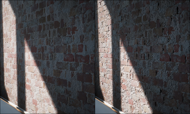
Figure 15.14 The same Material with only POM toggled, illustrating how it creates depth and helps define surfaces better than normal maps alone
POM does its magic by creating distorted UV coordinates that are then fed into each Texture’s UV input. All this complex math is done for you and set up as a Material Function that just requires some inputs like a Height Map to function.
Because POM affects every channel of your Material, breaking it off into its own Material is typically a good idea. Setting up the Material graph to accommodate all your other options would result in an overly complex Material that is doing too many things and can become a burden to maintain.
As you can see in Figure 15.15, the POM version of the Master Material is almost exactly the same as the standard Master Material. In fact, I created it by duplicating the Master Material in the Content Browser, and then edited it. The biggest addition is the Parallax Occlusion Mapping Function at the far left. Looking closer (see Figure 15.16), you can see it’s easy to set up.
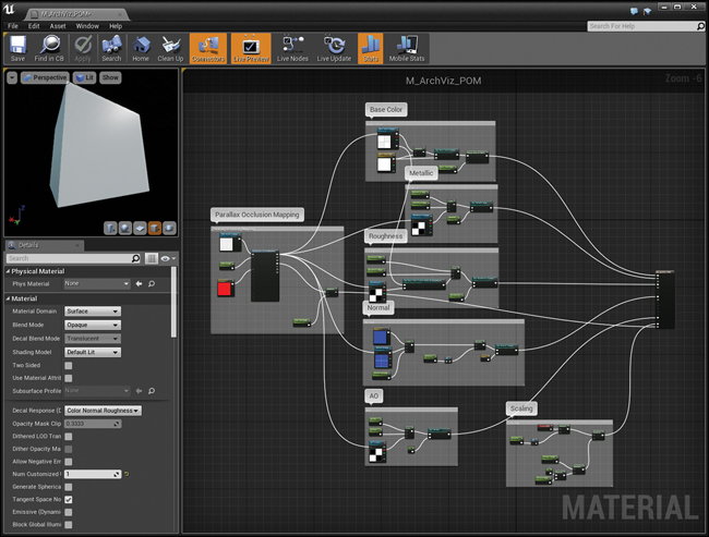
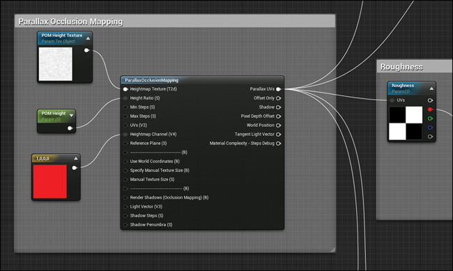
Figure 15.16 Detailed view of the Parallax Occlusion Mapping function; the resulting distorted UVs are then wired to each Texture Sample Parameter’s UV input
To setup the function, wire a Texture Object Parameter to the Heightmap Texture input. The Texture Object Parameter is different from the other Texture Parameters you have used elsewhere. The Texture Parameters you have been using return a color based on the Texture that’s assigned; a Texture Object Parameter outputs the Texture reference and it’s used for communicating with Material Functions rather than for rendering directly.
To create one, you must search explicitly for Texture Object Parameter in the Palette or use the right-click menu in the Material Editor.
Wire a POM Height Scalar Parameter wired to the Height Ratio input to set the strength of the effect. This should be set very low typically. A setting of 0.01 results in very strong effect. Good values are typically in the .001 to .005 range.
Wire a Constant Vector 3 node to the Heightmap Channel input. This defines what color channel will be sampled from the POM Height Texture node. In this case, set it to the Red channel by setting the Constant 3 value to 1,0,0.
Carpet and Rugs
Using POM with a high-frequency Texture like the carpet height map works wonderfully, giving depth and richness to even simple Materials (see Figure 15.17).
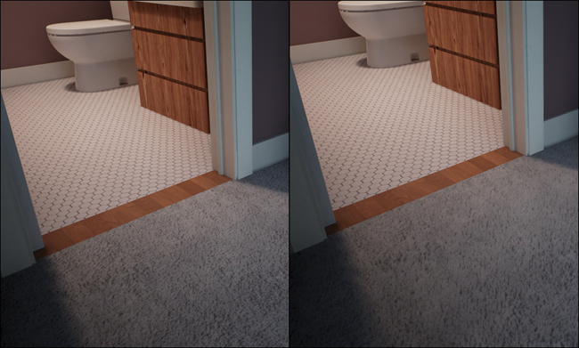
Figure 15.17 Carpet Material using POM to displace the fibers, which helps give the carpet depth and softness, especially in motion and in VR
Brick
Bricks are a classic example to demonstrate the capabilities of a rendering Engine—and for good reason. They are deceivingly difficult to render. POM yields good results and produces a quality most visualization artists are happy with (see Figure 15.18).
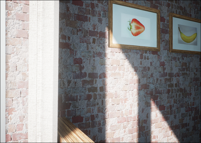
There are many sources online for great Brick and other Texture sources. The most important thing is to have an accurate height map. Getting the definition between the brick and grout makes a huge difference. Head to www.TomShannon3D.com/UnrealForViz for some links to my favorite places to source high-quality Textures.
Glass
Game Engines have long struggled to produce convincing translucent glass effects. The effective rendering of glass relies on refraction and reflection—and both are expensive and time-consuming effects to render (see Figure 15.19). With care, you can achieve great glass Material in UE4.
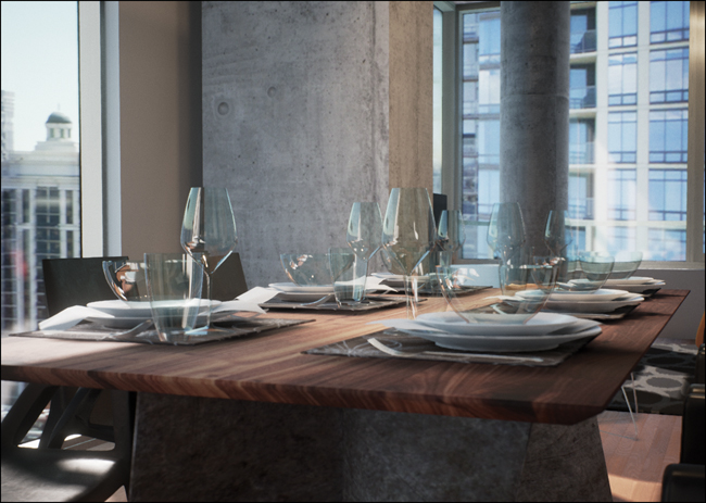
Figure 15.19 A single glass Material being used for the glasses, bowls, and the plate glass windows in the background
Several ways exist to create Glass Materials, each with advantages and drawbacks. Typically, the more accurate the Material is, the longer it takes to render. The Material demonstrated in Figure 15.19 is rather expensive to render, but it’s worth it because of the increased quality of simple translucent Materials.
Because we will need to set the Material to Translucent, we cannot easily use the Master Material as our basis for Glass Materials. We need a new Material.
The first thing you need to do is to make the Material you are creating Translucent. This lets it render after the main scene and be blended on top afterward. In the Material’s Detail panel with no nodes selected, set the Material’s Blend Mode to Translucent and the Lighting Mode to Surface Translucency Volume (see Figure 15.20).
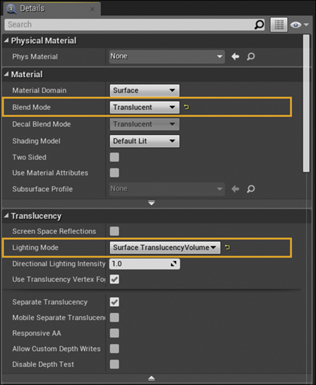
Figure 15.20 The glass Material’s Detail Panel with the Material’s Blend Mode set to translucent and the Lighting Mode set to Surface Translucency Volume
Most translucent Materials rely on the Opacity attribute to modulate the object’s opacity, allowing the scene behind it to be rendered. In this case, you will bypass that (setting the Opacity to almost 1.0) and provide your own version of the scene behind the glass, this one tinted and distorted.
To do this, you need to sample the Scene Texture (see Figure 15.21).
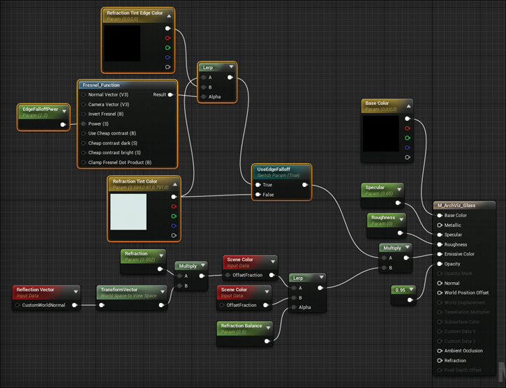
Figure 15.21 The ArchViz Glass Material network; bypassing the Opacity channel and building your own, modified scene Texture enables you to more effectively control the refraction and allow the surface reflections to stay bright
The Scene Texture is the rendered scene before the translucency is applied (translucent objects in UE4 are rendered after the rest of the scene then composited into the final frame). If you were to pipe the Scene Color directly to the Emissive attribute of the Material, it would make your glass look completely see through, aside from the surface reflections.
To distort the Scene Texture, you take the Reflection Vector (a Vector input provided by the Engine), transform it to your view (taking it from 3D worldspace to a 2D viewspace value) and then use that data to distort the Scene Color using the Offset Fraction. The offset fraction is a percentage (0.0–1.0) that lets you sample the Scene Color at a different pixel location on the screen.
This is a completely non-physically accurate refraction technique but it provides good-looking results.
You’ll notice two Scene Color nodes in the Figure 15.21 graph being Lerped together by the Reflection Balance Parameter. One is the distorted Scene Color whereas the other is unmodified. This gives a double-pane look that’s great for architectural visualization plate glass.
You can then easily tint the distorted and doubled-up Scene Color samples.
Assuming you have set Use Edge Falloff to true in your Material Instance based from this Material, the Fresnel Function provides a simple Fresnel falloff based on the surface normal relative to the camera. Using this falloff, the Tint is interpolated between the defined Refraction Tint Color Parameter to the Refraction Tint Edge Color Parameter. Otherwise, the Scene Color is tinted by the Refraction Tint Color Parameter.
You set the Material’s Roughness and Specular attributes using simple Scalar Parameters. You could expand on this Material to use Textures to drive any of these Parameters as well; however, this makes the Material much more expensive to render and should be used with caution.
Summary
Thanks to the PBR system in UE4, the visual Material Editor and the power and convenience of Material Instances, building beautiful Materials is quick and easy. It can be so much fun that going back to authoring Materials in 3D applications might be difficult.
Using Material Parameters and Material Instances make reusing your Material networks a snap, and the interactive node-based Material Editor lets you experiment, learn, and expand your Materials as your abilities and project requirements grow.