Chapter 3. Network Infrastructure
This chapter covers the following topics:
• Networking Terms and Concepts
• vSphere Standard Switch (vSS)
• vSphere Distributed Switch (vDS)
• Other vSphere Networking Features
This chapter contains information related to VMware 2V0-21.20 exam objectives 1.4, 1.7, 1.7.1, 1.7.2, 1.7.3, 1.7.4, 4.2, 4.14, 5.4
This chapter provides details for the network infrastructure, both physical and virtual, involved in a vSphere 7 environment.
“Do I Know This Already?” Quiz
The “Do I Know This Already?” quiz allows you to assess whether you should study this entire chapter or move quickly to the “Exam Preparation Tasks” section. Regardless, the authors recommend that you read the entire chapter at least once. Table 3-1 outlines the major headings in this chapter and the corresponding “Do I Know This Already?” quiz questions. You can find the answers in Appendix A, “Answers to the ‘Do I Know This Already?’ Quizzes and Review Questions.”
Table 3-1 ”Do I Know This Already?” Section-to-Question Mapping

1. You are configuring networking policies in your vSphere 7.0 environment. Which of the following policies are not available for vSphere Standard Switches?
a. Teaming and Failover
b. Security
c. Traffic Shaping
d. Port Blocking
2. You are configuring teaming policies in your vSphere 7.0 environment. Which of the following teaming options are not available for vSphere Standard Switches?
a. Route based on originating virtual port
b. Route Based on Physical NIC Load
c. Route based on source MAC hash
d. Use explicit failover order
3. You are configuring virtual networking in your vSphere 7.0 environment. Which of the following policies are not available for distributed switches but not for standard switches?
a. Inbound traffic shaping
b. Outbound traffic shaping
c. IPv6 support
d. CDP
4. Using NIOC, you reserved 1.0 Gbps for virtual machine system traffic on a distributed switch with eight 10 Gbps uplinks. If you reserve 512 Mbps for a network resource pool, what is the maximum reservation you can set in another network resource pool?
a. 0.5 Gbps
b. 1.0 Gbps
c. 7.5 Gbps
d. 79.6 Gbps
5. You want to tag Voice over IP data in your vSphere environment. Which step should you take?
a. Use a vSphere Standard Switch
b. Implement a filtering rule
c. Implement a rule with Acton = Tag.
d. Navigate to Menu > Tags and Custom Attributes
6. You want to leverage LAGs with your vSphere Distributed Switch. Which of the following is supported?
a. iSCSI software port binding
b. nested ESXi
c. 40 LAGs on a single distributed switch
d. 40 LAGs on a single host
7. You want to enable the vDS Health Check for virtual switch teaming. Which one of the following is a requirement?
a. At least two active NICs and two hosts
b. At least one active NIC from two hosts
c. At least two active NICs from at least one host
d. At least one active NIC from one host
8. You want to be able to use the vSphere Client identify the non-Cisco physical switch connected to a virtual switch uplink. Which one of the following should you implement?
a. A vSS with LLDP
b. A vSS with CDP
c. A vDS with LLDP
d. A vDS with CDP
9. You want to use DirectPath IO in your vSphere 7.0 environment. Which one of the following features is supported?
a. The virtual machine can run in a vSphere cluster
b. Hot adding virtual devices
c. Snapshots
d. Fault Tolerance
10. You want to create a custom TCP/IP Stack for your ESXi 7.0 server. Which one of the following is an available service that you can directly enable for the stack?
a. vSphere Replication NFC
b. NFS
c. vSphere HA heartbeat
d. iSCSI
Foundation Topics
Networking Terms and Concepts
Computer networking is built on the TCP/IP protocol suite that enables all types of computers, from many different vendors, to communicate with one another. This section introduces the essential network terminology and concepts for a vSphere environment.
Traditional Networking Terminology
Here is a list of definitions of commonly used networking terminology.
• TCP/IP: Transmission Control Protocol / Internet Protocol (TCP/IP) is a model used in the Internet that allows computers to communicate over long distances. It was developed by the United States Department of Defense (DOD) in the 1970’s and is defined in RFC documents. It includes components that breaks data into packets, delivers the packets to the proper destination, and reassembles data from the packets.
• RFC: Request for Comments (RFC) are the rules of the Internet and are managed by the Internet Engineering Task Force (IETF). Anyone can register to attend an IETF meeting and help draft and define the standards of communication for the internet.
• Physical Network: A physical network consists of physical network devices and cabling to which physical machines, such as ESXi servers, connect and use to communicate with other physical machines. A key component of a physical network is the physical Ethernet switch.
• MAC Address: Each network connected device has a Media Access Control (MAC) address. You can think of a MAC address as the physical network address of the device. Each server on a network has one or more network interface cards (NIC) that it uses to connect to the network. Each NIC has a unique MAC address. The MAC address is used to identify devices in an Ethernet network.
• IP Address: In addition to a MAC address, most devices are also assigned a unique IP Address. IP addresses are used to identify devices in an IP network, such as the Internet and private subnets.
• Physical Ethernet Switch: A physical Ethernet switch manages network traffic between devices that are directly connected to its ports. A switch has multiple ports, each of which can be connected to a single device or to another switch. The switch learns the MAC address of each connected device and uses it to build a MAC address table that maps the address to its port number. An Ethernet switch (also called a Layer 2 switch) acts as a traffic cop by directing each received network packet to the proper port based on the data in the MAC address table. Layer 3 switches include the use of IP routing tables to route traffic between subnets.
• Opaque Network: An opaque network is a network created and managed by a separate entity outside of vSphere, such as a logical segment created by VMware NSX-T. The opaque network appears as an object in the vSphere Client, but the vCenter Server cannot manage it. You can use the NSX Manager in NSX-T to manage the opaque network.
• Etherchannel: an Etherchannel is a logical channel formed by bundling together two or more links to aggregate bandwidth and provide redundancy. Another acceptable name for Etherchannel (an IOS term) is port channel (an NXOS term). Another acceptable name is Link Aggregation Group (LAG)
• LACP: A standards-based negotiation protocol used to dynamically build an Etherchannel. It is known as the IEEE 802.1ax (or IEEE 802.3ad) Link Aggregation Control Protocol (LACP). It is a protocol used to build Etherchannels (LAGs) dynamically. LAGs (Etherchannels) can also be built statically without using LACP.
• IEEE 802.1ax: The IEEE working group that defines port channel, EtherChannel and link aggregation. Originally, the working IEEE group was 802.3ad, but in 2008 it was replaced by 802.1ax.
• IEEE 802.3ad: the original IEEE working group for port channel, EtherChannel, and link aggregation. Although it has been replaced with 802.1ax, it is still referred to as IEEE 802.3ad.
Virtual NICs
Much like a physical server may have multiple NICs to connect to physical networks, a virtual machine may have multiple virtual NICs (vNICs) to connect to virtual networks. Much like a physical NIC, each vNIC as a unique MAC address. The vNIC appears as a traditional NIC to a virtual machine’s guest OS. The guest OS can assign IP addresses to vNICs.
In addition to virtual machine networking, ESXi requires network connectivity for host management activities and other purposes. To accommodate this need, you should configure one or more VMkernel virtual network adapters on each host. For example, when connecting the vCenter Server or the Host Client to an ESXi host, you provide the address (IP address or fully qualified host name) of a VMkernel virtual network adapter that is enabled for management traffic. Much like the way a virtual machine can use multiple virtual network adapters, each ESXi host may use multiple VMkernel network adapters.
Virtual Switch Concepts
A virtual switch is a software construct that acts much like a physical switch to provide networking connectivity for virtual devices within an ESXi host. Each virtual machine may use vNICs to connect to virtual ports on virtual switches. To gain access to the physical network, one or more of the host’s physical NICs should be connected to the virtual switch as uplinks. The virtual switch, which resides in the VMkernel, provides traffic management for all vNICs in the host and all the uplink’s incoming and outgoing Ethernet frames.
A virtual switch works at Layer 2 of the OSI Model. It can send and receive data, provide VLAN tagging, and provide other networking features. The virtual switch maintains a MAC address table that contains only the MAC addresses for the vNICs that are directly attached to the virtual switch. When an Ethernet frame is received by the virtual switch, it passes the frame to the appropriate port based upon its internal MAC address table. The virtual switch will update the physical switch with its internal MAC address table using ARP.
With vSphere 4.0, VMware renamed the original virtual switch to vSphere Standard Switch (vSS) and introduced the vSphere Distributed Switch (vDS). vSS and vDS behave similarly but are managed and controlled differently. Each vSS is configured and managed by a specific ESXi host. A vDS is configured and managed by the vCenter Server, which pushes the switch’s configuration to each participating host. The vDS has many more features than the vSS. All new features are built into the new vDS, while the vSS capabilities are limited.
Each virtual switch has many virtual ports. You can configure port groups (standard port groups) on a vSS. You can configure ports (distributed ports) and port groups (distributed port groups) on a vDS.
VLANs
A virtual LAN (VLAN) is a logical partition of a physical network at the data link layer (Layer 2). A VLAN is typically associated with a broadcast domain and is used to isolate the traffic from other networks. A broadcast domain is a collection of network devices with the ability to receive traffic destined to a broadcast address. A physical switch, by default, adheres to this behavior. With VLAN technology, the switch allows a single physical network to be divided into multiple network segments. This is achieved by modifying a unique header of the Ethernet frame and adding a tag to identify the membership within a specific VLAN. A VLAN can be used to sub-divide a broadcast domain to limit the number of network devices that can communicate when a broadcast packet is sent.
Note
IEEE 802.1Q is the networking standard that supports VLANs on an Ethernet network
ESXi provides VLAN support by allowing you the option to assign a VLAN ID to a virtual switch port group. The VMkernel is responsible for all tagging and untagging packets with VLAN IDs as the packets pass through the virtual switch. To properly assign VLANs, you must configure the port group to match the VLAN ID that has been configured at the physical switch. On a single virtual switch, you can configure multiple port groups and assign a unique VLAN ID to each port group. To support the multiple VLANs, the physical NIC that is used as the virtual switch’s uplink should connect to a physical switch port that is configured for VLAN trunking.
On a standard port group, the valid VLAN ID range is 1 to 4095, with 4095 being unique. The vSS forwards all packets from all ports to the port group assigned VLAN 4095. One use case is to implement packet sniffing or intrusion detection services (IDS) in a virtual machine. For sniffing or IDS, you must also enable promiscuous mode for the port group. Another use case is to support VLAN guest tagging (VGT).
On a distributed port group, the valid VLAN ID range is 1 to 4094. You cannot assign 4095 to a distributed port group. Instead, you can directly configure VLAN trunking using a distributed port group. On a distributed port group, you can select the VLAN Trunking option and identify the range of VLANs that are to be trunked. Setting a standard port group for VLAN 4095 is much like setting a distributed port group for VLAN trunking for VLANs 1 to 4094.
For example, consider this scenario. Your organization uses separate VLANs for production traffic (VLAN 101), test/development traffic (VLAN 102), QA traffic (VLAN 103), IP Storage traffic (VLAN 300), vMotion traffic (VLAN 310), and management traffic (VLAN 500). You want a virtual machine running Wireshark to be able to receive all virtual machine traffic and management traffic but not IP storage or vMotion traffic. You can configure the distributed port group to use VLAN trunking range 101 to 103,500. Or if you wanted to only exclude vMotion and IP storage traffic, you could define the range 1 to 103,500 to 4094.
vSphere Standard Switch (vSS)
A vSphere standard switch (vSS) is also called the Host-based switch, because it is configured and maintained within a specific ESXi host. The vSS data and management planes reside within a single host.
Much like a physical Ethernet switch, a vSS maintains and uses a MAC address table. But with a vSS, the VMkernel directly registers each connected vNIC’s MAC address, along with its virtual port, in the virtual switch MAC address table. The vSS does not observe network packets to learn the MAC address. The vSS sends all packets whose destination address does not match a connected vNIC to the physical NIC uplinks.
During a default ESXi installation, the host is configured with one virtual switch, identified as vSwitch0, with a physical NIC uplink, identified as vmnic0. The default virtual switch contains a virtual machine port group named VM Network and a port group named Management Network. VM Network is a port group for connecting virtual machines (a virtual machine port group). Management Network is a port group that contains a single VMkernel virtual network adapter (vmk0) that is used for management purposes, such as connecting to vCenter Server. A VMkernel virtual adapter is commonly called a VMkernel port. You can create additional standard switches. You can add virtual machine port groups and VMkernel virtual network adapters to existing standard switches. You can assign unique labels and policies to virtual machine port groups. These policies, which include NIC teaming, security, and traffic shaping policies, are applied to the virtual machines connected to the port group.
For example, Figure 3-1 is a diagram representing a standard virtual switch with two virtual machines connected to a port group named VM Network, two VMkernel ports (one named Management Network and one named vMotion), and two physical NIC uplinks (vmnic0 and vmnic1).
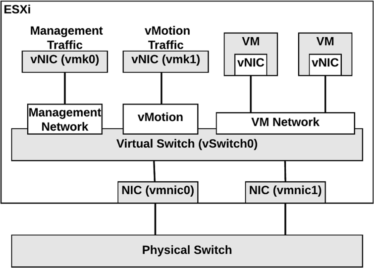
Figure 3-1 A Sample Virtual Switch
Each virtual machine typically has one or more vNICs to allow network communication. To connect a virtual machine to a vSS, you should connect one of its vNICs to a virtual machine port group on the vSS. To allow the virtual machines to communicate with virtual machines on other hosts, connect the port group to one or more physical NIC uplinks in the vSS. The physical NIC should be connected to a physical Ethernet Switch. The inbound and outbound Ethernet frames travel through the physical NIC uplink on the vSS. Virtual machines in a port group that do not have a physical NIC uplink can only communicate with other vNICs on the same host and port group.
The vSS provides features such as VLAN tagging, NIC Teaming, network security policies, and traffic shaping. The feature set provided by a vSS is smaller than the feature set provided by a vDS or a physical Ethernet Switch. The vDS feature set is covered later in this chapter, along with a comparison of vSS and vDS.
A vSS does not have some of the vulnerabilities of a physical switch. For example, it is not susceptible to MAC address flooding attacks, because it does not use observed data to populate its MAC address table. The following lists contains other common network vulnerabilities and a brief explanation why a vSS is safe from the vulnerability.
• 802.1q tagging attacks: A vSS does not perform the dynamic trunking required for this type of attack.
• Double-encapsulation attacks: A vSS drops any double-encapsulated frames that a virtual machine attempts to send on a port configured for a specific VLAN.
• Multicast brute-force attacks: A vSS does not allow frames to leave their correct broadcast domain (VLAN).
• Spanning tree attacks: A vSS does not participate in spanning tree protocol
A vSS is not a managed switch, so it cannot be configured and monitored using traditional networking models and utilities. Instead, you can manage a vSS using VMware provided tools, such as the vSphere Client, the Host Client, vCLI, ESXi shell, or PowerCLI.
The main vSS switch property that you can set directly with the vSphere client is the MTU size, which is explained next.
MTU
The standard size for Ethernet packets, or frames, is 1500 bytes. Using larger (jumbo) frames can provide better utilization of a fast network link. To allow jumbo frames on a vSS or vDS, you must set the virtual switch’s Maximum Transmission Unit (MTU) to a value larger than 1500 bytes, such as 9000 bytes. To use jumbo frames, you must configure the network to support it end to end, including physical NICs and physical switches. To allow a virtual machine to use jumbo frames, you must configure the virtual machine to use the VMXNET3 virtual network adapter (E1000 and E1000E adapters do not support jumbo frames.) and enable jumbo frames inside the guest operating system. To allow VMkernel services, such as IP-based storage, vMotion, fault tolerance, and VSAN to use jumbo frames, you must set the MTU setting for the VMkernel network adapter to a value greater than 1500 bytes.
Failure to properly configure MTU to support jumbo frames end to end typically results in poor network performance. With vDS, you can enable a health check to warn you of mismatched configuration between the vDS and the physical network hardware.
vSS Network Policies
You can apply network policies to standard and distributed switches to utilize and configure specific features. On a vSS, you can apply policies to the switch, which automatically propagate to each port group. At the port group level, you can override policies applied to the switch and apply unique policies to a port group. On a vDS, you have more flexibility for applying policies, such that you can override policies at the port level.
On a vSS, you can set the following network policies:
![]()
• Teaming and Failover
• Security
• Traffic Shaping
• VLAN
You can set the policies directly on a vSS. To override a policy at the port group level, just set a different policy on the port group.
A vDS supports additional policies. See the vDS Network Policies section for details.
NIC Teaming Policies
When you connect two or more physical NICs (pNICs) to the same vSS you should decide which NIC Teaming option to utilize. The two main purposes of NIC Teaming are to improve availability (by eliminate a single point of failure) and to handle large workloads (by spreading traffic across multiple uplinks). The following NIC Teaming options are available on vSS and vDS. The vDS has additional teaming options that are addressed in a later section.
• Route based on originating Virtual Port: This is the default option. Its load balancing is based on the originating port ID of the virtual machine. When a new virtual machine gets connected to the port group, the virtual switch uses the virtual machine’s port ID to select one of the pNICs from the active uplinks list to direct outbound traffic. Typically, this results in near even distribution of virtual machine among the uplinks. If an uplink fails, the switch redirects the traffic from the failed uplink to a surviving uplink.
• Route based on IP hash: In this load-balancing method, the switch reads the source and destination IP address of each outbound packet and uses a hash to determine which uplink to place the packet. The selection process is resource intensive, because the VMkernel is going to examine the header of each ethernet packet. With this method a single VM could send packets to different destinations, using different uplinks, which can improve throughput. To support this method, the switch must support IEEE 802.3ad and you must configure an Etherchannel on the physical switch.
• Route based on source MAC hash: This load-balancing method is based on source MAC address. The switch processes each outbound packet header and generates a hash using the Least Significant byte (LSB) of the MAC address. It uses the hash to decide which active uplink should be used to place the packet.
• Use explicit failover order: When this option is chosen, all outbound traffic uses the first uplink that appears in the active uplinks list. If the first uplink fails, the switch redirects traffic from the failed uplink to the second uplink in the list.
Note
For each of these methods, the virtual switch does not consider the virtual machine’s active workload in the load balancing decision making. A vDS offers a load based NIC teaming option that is addressed later in this chapter.
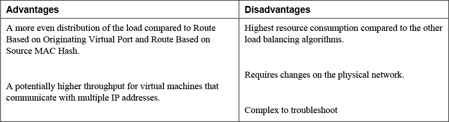
Table 3-2 provides some advantages and disadvantages for selecting Route Based on IP Hash.
Table 3-2 Advantages and Disadvantages of IP Hash NIC Teaming
Network Security Policies
As an administrator, you can define Network Security Policies to protect network traffic against MAC address impersonation and unwanted port scanning. The security policies of the virtual switches are implemented in Layer 2 of the TCP/IP stack. You can use the network security policies to secure traffic against Layer 2 attacks.
It is important to understand how the virtual machine MAC addresses are defined, since it plays a part in the security policies. Each vNIC in a virtual machine has an initial MAC address and an effective MAC address. The initial MAC address is assigned when the adapter is created. It can be modified from outside the guest operating system, but it cannot be changed by the guest operating system. The effective MAC address is typically assigned the same value as the initial MAC address when the adapter is created. The effective MAC address can be changed by the guest OS. The effective MAC address is used when filtering incoming packets. When the guest OS changes the effective MAC address, the adapter receives packets destined for the new effective MAC address. When sending a packet, the guest OS typically places its effective MAC address in the source MAC address field of the Ethernet frame.
A guest OS can send frames with an impersonated source MAC address, which facilitates impersonation and malicious attacks. To guard against this risk, you can leverage security policies on vSS port groups and vDS distributed port groups. There are three available options for the network security policies, which are promiscuous mode, MAC address changes, and forged transmits.
• Promiscuous Mode: For a vSS port group, the default value is Reject. The default behavior is the vNIC will receive only those frames that match the effective MAC address. If changed to Accept, then the virtual switch sends all frames on the wire to the vNIC, allowing virtual machines to receive packets that are not destined for them. This setting allows the use of tools such as TCPDump or Wireshark inside a guest operating system.
• MAC Address Changes: For a vSS port group, the default value is Accept. The default behavior is that ESXi accepts the effective MAC address change. If changed to Reject, the behavior changes such that ESXi does not honor requests to change the effective MAC address to an address that is different from the initial MAC address. Instead, it disables the virtual switch port, until the effective MAC address matches the initial MAC address. The guest OS is unaware that the request was not honored.
• Forged Transmits: For a vSS port group, the default value is Accept. The default behavior is ESXi does not compare source and effective MAC addresses and does not drop the packet due to a mismatch. If changed to Reject, then ESXi compares the source and effective MAC addresses and drops the packet if the packet if the addresses do not match.
Note
In a vDS, the default value for each of these three security policies is Reject.
Traffic Shaping Policy
A virtual machine’s network bandwidth can be controlled by enabling traffic shaping. Traffic shaping is defined by average bandwidth, peak bandwidth, and burst size. Network traffic shaping can be configured on standard switches or distributed switches, but by default traffic shaping is disabled. You can apply a traffic shaping policy to each vSS port group, each vDS distributed port, or each vDS distributed port group. On standard switches, traffic shaping can only be configured for outbound traffic. On vDS, it can be configured for both outbound and inbound traffic. When you enable traffic shaping for a standard switch or port group, you can configure the following options.
• Average bandwidth (Kbps) is the allowed average load for a port. It is the allowed number of kilobits per second for traffic through a port, averaged over time.
• Peak bandwidth (Kbps) is the allowed maximum number of kilobits per second of traffic through a port when it is sending or receiving a burst of traffic. This number tops the bandwidth that a port uses when it is using its burst bonus that is configured using the Burst size parameter. The peak bandwidth cannot be smaller than the average bandwidth.
• Burst size (KB) is the maximum number of kilobytes to allow in a burst. If this parameter is set, a port might gain a burst bonus when it does not use all its allocated bandwidth. You can define an average bandwidth allotment for the virtual machines connected to a port group. If the virtual machines have not used the allotted bandwidth, then the system may grant a burst bonus, allowing the virtual machines to send some data, limited by the burst size, at a faster rate, up to the peak bandwidth.
VLAN Policies
VLANs are described in the VLANs section in this chapter.
You can apply a VLAN policy to a vSS, such that all port groups on the vSS are associated with a single VLAN. Optionally, you can override the VLAN setting per port group, such that all the virtual machines in the port group are associated with the same VLAN. A major use case for multiple virtual machine port groups is to provide a simple means to place different sets of virtual machines onto separate VLANs. In this case, you should apply a unique VLAN policy to each virtual machine port group.
Distributed Virtual Switch (vDS)
A vSphere Distributed Switch (vDS) acts as a single virtual switch for all associated hosts in a data center. It provides centralized provisioning, monitoring, and management of virtual networks for associated hosts and virtual machines. You create and configure distributed switches on a vCenter Server system. The vCenter Server propagates the switch configuration to each connected ESXi host in the form of a host proxy switch. The ESXi host provides the data plane for the I/O traffic. The data plane implements the packet switching, filtering, tagging, and other features for the ethernet packet. The management plane is provided by vCenter Server. Figure 3-2 shows the architecture of a vDS, including its management plane and data plane.

Figure 3-2 vDS Architecture
Distributed Port Group
The ports in a vDS, which are called distributed ports, are where the VMkernel virtual network adapters and virtual machine vNICs connect. A set of distributed ports is a called a distributed port group. A vDS provides distributed port groups to simplify the configuration and management of distributed ports. You can apply unique network labels to each distributed port group. You can configure NIC teaming, VLAN, security, traffic shaping, and other policies to a distributed port group, which applies the policies to the underlying distributed ports. When you connect a vNIC to a vDS, you can choose the distributed port group rather than a specific distributed port.
Uplink Port Group
An uplink port group is similar to a distributed port group, except that it is used to manage the physical connections for hosts. An uplink port group, which is defined during the creation of the distributed switch, contains one or more uplinks. An uplink (dvuplink) is where you map the hosts’ physcial NICs that connect the vDS to the physical network. When you change settings, such as NIC Teaming settings, that involve uplink port groups, the setting are automatically applied to each host and the appropriate NICs.
Comparison of vSS / vDS
![]()
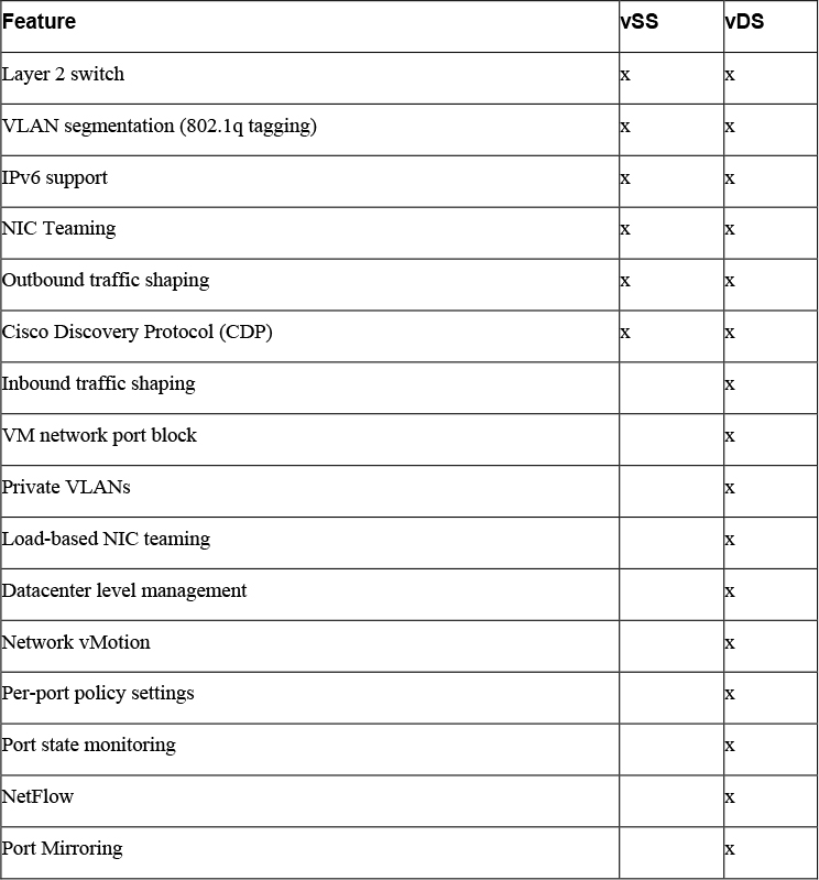
You can define custom names for each vDS, distributed port group, and uplink port group using the vSphere Client. At the switch level, you can make several more settings and take more actions with a vDS than a vSS, such as creating Private VLANs and configuring Port Mirroring Sessions. vDS offers many advantages over vSS, but requires Enterprise Plus licensing. Table 3-3 provides a side-by-side comparison of the features that are available in vSS and vDS.
Table 3-3 Comparison of vSS and vDS Features
vDS Network Policies
On a vDS, you have more flexibility for applying policies that you do with a vSS. You can apply policies to the distributed port group, which automatically propagate to each distributed port. At the distributed port level, you can override policies applied to the distributed port group and apply unique policies to a distributed port. Likewise, you can apply policies to uplink port groups and override the policies at the uplink port level.
At the distributed port group level, you can control which network policies are available for override at the distributed port group level. For example, if you configure the distributed port group to allow VLAN policy override at the port level, then you can set a VLAN ID directly on a distributed port. Otherwise, you cannot.
Like with a vSS, you can apply the following network policies for vDS. As previously stated, you can apply these policies on the distributed port group and distributed port levels.
• Teaming and Failover
• Security
• Traffic Shaping
• VLAN
With a vDS, you can apply the following additional policies, which are addressed in upcoming sections in this chapter.
• Monitoring
• Traffic filtering and marking
• Resources allocation
Port blocking
In comparison with vSS, the vDS provides additional Teaming and Failover policy options, which are addressed in the Load-based NIC Teaming and LACP Support sections in this chapter. In comparison with vSS, the vDS provides additional Traffic Shaping options, which are addressed in the Inbound Traffic Shaping section in this chapter.
Inbound Traffic Shaping
Distributed virtual switches can do both inbound and outbound traffic shaping, whereas standard virtual switches handle just outbound traffic shaping. Specifically, you can set configure the average bandwidth, peak bandwidth, and burst size on a distributed port group and apply it to ingress or egress traffic (inbound or outbound to the distributed port).
Port Blocking Policies
When needed, you can block traffic to specific distributed ports. For example, if a virtual machine is broadcasting a lot of traffic due to a broken or hacked application and starts consuming a large portion of the network bandwidth, you may want to temporarily block traffic to its distributed port. This is particularly useful if you are a network administrator who has permissions to modify the vDS, but do not have permission to modify the virtual machine.
As with other policies, to allow individual port blocking, you first need to allow port blocking policy override on the distributed port group. Optionally, you can block all ports in a port group.
Load-based NIC Teaming
In addition to the NIC teaming options (originating virtual port ID, source MAC hash, IP hash, and explicit failover order) provided by standard switches, the vDS offers load-based teaming. Load-based NIC teaming (or Route Based on Physical NIC Load) checks the current load on the uplinks and takes steps to migrate traffic from overloaded uplinks to less active uplinks. With load-based teaming, each vNIC is initially assigned to an uplink based upon the originating virtual port ID. If an uplink’s load exceeds 75 percent of its capacity over a 30-second interval, then the port ID of the virtual machine with the highest I/O is moved to a different uplink.
Load-based teaming offers lower overhead than IP-based load balancing and it does not require the physical switches to support 802.3ad (EtherChannel / link aggregation).
Resource Allocation Policy
![]()
When you apply a resource allocation policy to a distributed port group, you can assign a network resource pool to the port group. Network resource pools leverages Network I/O Control to allocate resources for network traffic, as explained in the following sections.
Network I/O Control
Network I/O Control (NIOC) was introduced in vSphere 4.1 when VMware added support for physical NIC’s with speeds greater than 1 Gb. It became common for servers to have fewer NICs with multiple types of network traffic sharing the bandwidth. VMware uses NIOC as an additional layer of packet scheduling in the hypervisor to prioritize network traffic.
When you create a vDS in vSphere 7.0, Network I/O Control is enabled by default. Each virtual port has a network port queue where the network scheduler gets the packet and transmits it based upon the shares, reservations, and limit settings for each network port. The vDS recognizes the following network traffic types: management, Fault Tolerance, NFS, vSAN, vMotion, vSphere Replication, vSphere Data Protection Backup, and virtual machine traffic. With default settings, NIOC does not directly limit or guarantee network bandwidth to any system traffic type. In other words, the reservation for each traffic type is 0 and the limit is set to unlimited. By default, NIOC provides a higher relative priority to virtual machine traffic, that is applied during periods of network contention. In other words, the default virtual machine traffic shares (100) are twice as many as the shares for the other types of system traffic (50).
You can change the limit for any system traffic type to reflect the maximum amount (in Mbps or Gbps) that the traffic type can consume on a single physical NIC.
You can change the reservation for any system traffic type to establish a specific amount (in Mbps) that the traffic type is guaranteed on a single physical NIC. This amount cannot exceed 75 percent of the bandwidth of the lowest capacity NIC that is servicing the traffic type. If you reserve resources for virtual machine traffic, you can use network resource pools to delegate the reserved resources.
Network Resource Pools
A network resource pool is a mechanism that enables you to apply a part of the bandwidth that is reserved for virtual machine system traffic to a set of distributed port groups. By default, no network resource pools exist.
For example, if you reserved 2.0 Gbps for virtual machine system traffic on a distributed switch with four uplinks, then the total aggregated bandwidth available for virtual machine reservation on the switch is 8.0 Gbps. Each network resource pool can reserve a portion of the 8 Gbps capacity. If you create a network pool named PG-A and set it to reserve 3 Gbps, then you have 5 Gbps that you can use for other network pools, as illustrated in Figure 3-3.

Figure 3-3 Network Resource Pools Example
The bandwidth quota that is dedicated to a network resource pool is shared among the distributed port groups associated with the pool and is applied to the virtual machines connected to the associated distributed ports.
With NIOC version 3, you can set shares, reservation, and limit on virtual machine vNICs, much like you can for the virtual machine’s CPU and memory. To fulfill the network reservations (guarantees), NIOC uses a traffic placement engine. For virtual machines that have network reservation configured, the distributed switch attempts to place the virtual network adapter traffic on a physical adapter that can supply the required bandwidth and is in the scope of the active teaming policy. The total bandwidth reservation for virtual machines in a network resource pool cannot exceed the reservation of the pool.
The actual limit and reservation applied to a virtual network adapter may be impacted by distributed port group’s traffic shaping policy. For example, if a vNIC’s limit is set to 300 Mbps, and the average bandwidth and peak bandwidth applied by traffic shaping is 200 Mbps, then the effective limit becomes 200 Mbps.
To meet the network guarantees (reservation) for a virtual machine, vSphere implements admission control at the host and cluster levels based on bandwidth reservation and teaming policy. A distributed switch applies bandwidth admission control by using NIOC to verify the following.
• A physical adapter is available that can supply the guaranteed bandwidth to the VM network adapters.
• The virtual network adapter’s reservation is less than the free quota in the network resource pool.
With NIOC version 3, vSphere DRS cluster places the virtual machine on a host that can fulfill the reserved bandwidth for the virtual machine according to the active teaming policy. In the following situations, vSphere DRS migrates a virtual machine to another host to satisfy the virtual machine’s bandwidth reservation.
• The reservation is changed to a value that the initial host can no longer satisfy.
• A physical adapter that carries traffic from the virtual machine is offline.
In the event of a host failure or isolation, vSphere HA powers on a virtual machine on another host in the cluster according to the bandwidth reservation and teaming policy. To use network admission control in a vSphere DRS or vSphere HA cluster, you should perform the following tasks:
• Allocate bandwidth for the virtual machine system traffic.
• Configure the bandwidth requirements of virtual machines connected to the distributed switch
NetFlow and Monitoring Policy
NetFlow is a feature that was introduced by Cisco in the mid 1990’s, and eventually open sourced and controlled by IETF. VMware added it to the vSphere 5.0 release, and it was originally based upon NetFlow version 5. Netflow is a switch feature that collects IP network traffic as it enters or exits an interface. Netflow data allows you to have an overview of traffic flows, based on the network source and destination.
The main purpose is to collect IP network traffic that is flowing through a vSphere Distributed Switch. The current supported version for the vDS is NetFlow version 10, which is identified as IPFIX.
NetFlow allows administrators to forward network flows to a centralized NetFlow collector. These flows can include virtual machine to virtual machine flows, virtual machine to physical device flows, and physical device to virtual machine flows. The collector can be a physical device on the network or a virtual machine. The collector gathers the flows to enable network analysis and troubleshooting. You can set a sampling rate to collect Network flows. For example, if you set the sampling rate to 4, NetFlow samples one packet, then drops (skips) the next four packets. If the sampling rate is zero, NetFlow samples every packet (skips zero packets).
By default, NetFlow is turned off on the vSphere Distributed Switch. If you enable it, you can set the Collector IP address, Collector port, and other settings. To collect data only from the virtual machines on the same host, you can enable Process internal flows only.
After configuring NetFlow on the vDS, you can configure Monitoring Policies on vDS port groups and ports.
Traffic Filtering and Marking Policy
With vDS, you can implement a traffic filtering and marking policy to protect the virtual network from unwanted traffic and security attacks. The traffic filtering in a vDS uses simple filtering rules, much like the filtering in many physical switches. As an example, you could create a simple Permit rule that allows the specified traffic, while blocking everything else. Or you could create a Deny rule, which blocks the specified traffic, while allowing everything else.
A marking policy is a way to mark traffic with a priority tag that is utilized during times of contention on a physical switch. You are applying a tag to the Ethernet Header or IP Header as the Ethernet frame comes enter and exit your virtual switch. You can mark the traffic with a Class of Service (CoS) tag in a layer 2 Ethernet Header. Or you could mark the traffic with a Differentiated Service Code Point (DSCP) tag in a layer 3 IP Header. Higher tagged packets will move to the front of the queue on a physical ethernet switch during times of contention, while lower or untagged packets will be best effort.
With vDS, you can apply filters on data traveling between the vNIC and distributed port and between the uplink port and physical NIC. The following list provides the major steps.
Step 1. Enable traffic filtering and marking on the distributed port group or uplink port group.
Step 2. Mark traffic on the distributed port group or uplink port group.
Step 3. Configure filters on the distributed port group or uplink port group.
Step 4. Define traffic rules for distributed port group or uplink port group
When marking traffic, you can create a rule where you configure qualifiers to identify the data to be tagged and set the Action to Tag. You can use system traffic qualifiers (such as NFS), MAC traffic qualifiers (to match by MAC address and VLAN ID), and IP traffic qualifiers (to match by IP version and IP address).
For example, to mark Voice over IP (VoIP) whose source IP is 192.168.2.0, you can specify the following parameters in the rule.
• Action: Tag
• DSCP value: 26
• Traffic direction: Egress
• Traffic qualifiers: IP Qualifier
• Protocol: UDP
• Destination port: 5060
• Source address: IP address matches 192.168.2.0 with prefix length 24
vDS Settings and Features
The following sections provide details on other vDS settings and features.
Private VLANs
Private VLANs (PVLANs) are an extension of the VLAN standard. They are not double encapsulation but do allow a VLAN to effectively be subdivided into other VLANs. This is useful for a hosting provider that has run out of VLANs or any environment where 4094 VLANs is not enough.
A VLAN that is to be subdivided becomes known as the primary private VLAN. This primary PVLAN is then carved up into one or multiple secondary PVLANs that exist only within the primary. When a virtual machine or VMkernel port sends a packet, that packet is tagged at the distributed port group level on the vDS. Because this is not double encapsulation, packets only travel with one VLAN tag at a time. However, physical switches could be confused by seeing MAC addresses tagged with more than one VLAN tag, unless the physical switches are PVLAN aware and have their PVLAN tables configured appropriately. If the physical network is configured correctly, it identifies that the secondary PVLAN exists as part of the primary. This is defined in the PVLAN tables on the physical networking switches themselves. There are three different types of secondary PVLANs:
• Promiscuous: Nodes in a promiscuous secondary PVLAN can communicate with other nodes in the same PVLAN and all nodes in any secondary (community or isolated) PVLANs in the same primary PVLAN.
• Community: Nodes in a community secondary PVLAN can communicate with other nodes in the same PVLAN and nodes in a promiscuous secondary PVLAN in the same primary PVLAN. Nodes in a community secondary PVLAN cannot communicate with nodes in other community or isolated secondary PVLANs.
• Isolated: Nodes in an isolated secondary PVLAN can communicate with nodes in a promiscuous secondary PVLAN in the same primary PVLAN. Nodes in an isolated secondary PVLAN cannot communicate with other nodes in the same PVLAN or with nodes in other community or isolated secondary PVLANs
Data Center Level Management
The vSphere Client provides a single pane of glass for provisioning, configuring, and managing a vDS, which can be used by up to 2,500 ESXi servers. At the data center level, you can perform many network management tasks, such as the following.
• Create a vDS
• Attach hosts to the vDS
• Create distributed port groups
• Assign policies to port groups
• Migrate virtual machines and VMkernel virtual network adapters to the vDS
• Monitor alerts, tasks, and events.
• Monitor port state
• Manage network resources
Port State Monitoring
In the vSphere Client, you can view details for each vDS port, such as the connected virtual machine, runtime MAC address, link state (link up, link down, blocked, or information unavailable),
Port State with vMotion
A virtual machine connected to a vDS maintains its virtual switch connection when migrating to a different ESXi host. From a virtual networking perspective, the virtual machine has not moved. It remains connected to the same distributed port, with no disruption to the policies and statistics that are tied to that distributed port.
When you perform a migration of a virtual machine connected to a vSS, the virtual machine is attached to a different port on a different virtual switch. The policies and statistics associated with the original port are not carried with the virtual machine. The virtual machine is subject to the policies associated with the destination port group and virtual switch.
Port Mirroring
![]()
Port mirroring allows administrators to duplicate everything that is happening on one distributed port to then be visible on another distributed port. This allows you to do granular per-port based network analysis, by gathering the entire traffic stream coming in and out of a monitored port. To get started, you create a port mirroring session where you identify the session type, session properties, traffic source and destination.
For the session type, you can specify one of the following options.
• Distributed port monitoring: Mirrors packets from a set of distributed ports to other distributed port groups.
• Remote mirroring source: Mirrors packets from a set of distributed ports to specific uplinks.
• Remote mirroring destination: Mirror packets from a set of VLANs to distributed ports.
• Encapsulated remote mirroring (L3) source: Mirrors packets from a set of distributed ports to the IP address of a remote agent.
The session properties are dependent on the session type, but include the following settings.
• Name: Uniquely identifies the session.
• Status: Enables or disables the session.
• Description: Describes the session.
• Sampling Rate: Sets the rate at which packets are sampled
• Normal I/O on destination ports: Available only for distributed port and uplink destinations. You can disable this option to allow mirrored traffic out on destination ports, but disallow mirrored traffic in on destination ports.
• Mirrored packet length: Limits the size of mirrored frames
• Traffic source: Identifies the source of the traffic.
Typically, the mirrored data is sent to a network sniffer or intrusion detection system.
Port Binding and Allocation
Virtual network adapters (for virtual machines and the VMkernel) must connect to virtual switch ports to communicate on a network. Port binding determines how virtual machines are bound or attached to virtual switch ports. To control the port assignment, you can choose to use static binding or ephemeral binding.
• Static binding: With Static Binding (which is the default), when a vNIC attaches to a port in a distributed port group, the connection is static – meaning the virtual machine remains attached to the port, regardless of the power state of the virtual machine. This binding is performed and controlled by vCenter Server.
• Ephemeral: Ephemeral means there is no binding of the vNIC to a specific virtual switch port. With this setting, virtual switch ports are created and deleted on demand by the host. At any moment, the number of ports for an ephemeral bound distributed port group is equivalent to the number of running vNICs connected to the port group.
Note
Having an available ephemeral port group is useful in cases where vCenter Server is down and you need to assign a virtual machine to a port group. For example, if a vCenter Server appliance (VCSA) is connected to a distributed port group with static binding, you may fail to reconnect the VCSA to the network after restoring the VCSA, because vCenter is required to assign the port. In this case, you should be successful in connecting the restored VCSA to ephemeral-binded distributed port group, because the ESXi host will assign the port.
You can control the number of ports and the port allocation in a distributed port group. The port allocation can be Fixed or Elastic.
• Elastic: (default) Ports in the port group are created and removed on demand. For example, if the port group is configured for 8 ports and Elastic port allocation, then you can connect 9 vNICs to the port group, because when you connect the eighth vNIC to the port group, 8 more ports are automatically added.
• Fixed: The number of ports in the port group is static. Ports are not automatically created or removed. For example, if the port group is configured for 8 ports and Fixed port allocation, then you cannot connect 9 vNICs to the port group. When you attempt to connect the ninth vNIC to the port group, you will get an error stating “no free port is available”.
In vSphere 7.0, the default settings for a distributed port group is static binding, elastic port allocation, and eight ports.
In the past, the Ephemeral setting seemed like the easiest way to go because it required the least administrative effort to address an ever-growing environment. That changed in vSphere 5.1, when static port binding became “elastic” by default.
LACP Support
In vSphere 7.0, vDS supports LACP. This means you can connect ESXi hosts to physical switches by using dynamic link aggregation. You can create multiple link aggregation groups (LAGs) on a distributed switch to aggregate the bandwidth of physical NICs on ESXi hosts that are connected to LACP port channels. This enables you to increase the network bandwidth, redundancy, and load balancing to the port groups. You need to configure each LAG with two or more ports and connect physical NICs to the ports. Within the LAG, the ports are teamed, such that the network traffic is load balanced between the ports using a LACP hashing algorithm.
For each LAG on a vDS, a LAG object is created on each associated host proxy switch. The same number of ports that you assign to the LAG on the vDS are assigned to the corresponding LAG on the proxy switch on each host, as illustrated in Figure 3-4.
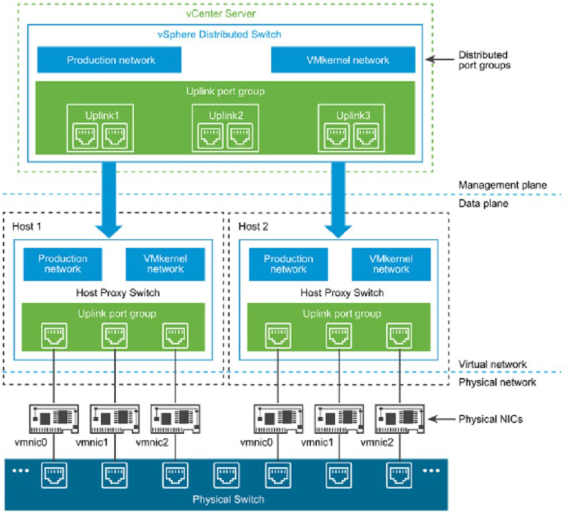
Figure 3-4 Example LACP Configuration with a vDS
On a host proxy switch, a physical NIC can connect to just one LAG port. On the distributed switch, a LAG port can connect to multiple physical NICs from different hosts. The physical NICs that are connected to the LAG ports must connect to links that participate in an LACP port channel on the physical switch.
A vDS supports up to 64 LAGs. A host supports up to 32 LAGs. The LAG configuration for a vDS may be limited by the physical network configuration.
The following limitations apply for LACP support in on a vDS.
![]()
• LACP support is not compatible with software iSCSI port binding. (iSCSI multipathing is supported if iSCSI port binding is not used.)
• LACP support settings do not exist in host profiles.
• LACP is not supported with nested ESXi.
• LACP support does not work with the ESXI dump collector.
• LACP control packets (LACPDU) are not mirrored by vDS port mirroring
• The vDS teaming and failover health check (see the following section) does not support LAG ports. (LAG port connectivity is checked by LACP.)
• Enhanced LACP support only works when a single LAG handles traffic per distributed port group.
vDS Health Check
By default, vDS Health Check is disabled, but you can enable it to check for several specific network inconsistencies. It identifies problem but does not attempt to fix the problem. You can use vDS health checks to regularly examine certain settings on the distributed and physical switches to identify common errors in the networking configuration. The default interval between health checks is 1 minute. The health checks generate MAC addresses to use during testing. Depending on your selected options, the number of generated MAC addresses can be significant. If you disable health checking, the MAC addresses will age out of your environment. For this reason, you may want to enable health check temporarily.
Table 3-4 provides a summary of the health checks available in vDS.
Table 3-4 vDS Health Checks

The potential values for VLAN Health Status, MTU Health Status, and Teaming and Failover Health Status include Normal, Warning, or Unknown. If the VLAN trunk ranges configured on the distributed switch match the trunk ranges on the physical switch, the VLAN Health Status is Normal. If the MTU settings configured on the distributed switch match the trunk ranges on the physical switch, the MTU Health Status is Normal. If the physical switch ports participate in an EtherChannel and the distributed port group teaming policy is IP hash, the Teaming and Failover Health Status is Normal. Also, if the distributed port group teaming policy is set to Port Based , MAC Hash, or explicit failover, and physical switch ports do not participate in an EtherChannel, the Teaming and Failover Health Status is Normal.
Other vSphere Networking Features
The following sections provide details on other networking features supported in vSphere 7.0 that are not covered previously in this chapter.
Multicast Filtering Mode
vDS 6.0.0 and later supports basic multicast filtering mode and multicast snooping mode.
Basic Multicast Filtering: In basic multicast filtering mode, a virtual switch (vSS or vDS) forwards multicast traffic for virtual machines according to the destination MAC address of the multicast group, which is based on the MAC address generated from the last 23 bits of the IPv4 address of the group. When a guest operating system joins a multicast group, it pushes the group multicast MAC address to the network through the virtual switch. The virtual switch records the port to destination multicast MAC address mapping in a local forwarding table. The switch does not interpret IGMP messages. Instead, it sends messages directly to the local multicast router, which interprets the messages and takes the appropriate action.
The basic mode has the following restrictions:
• A virtual machine may receive packets from the wrong groups because the switch forwards packets based on the multicast group’s destination MAC address, which can be potentially mapped up to 32 IP multicast groups.
• Due to a limitation of the forwarding model, a virtual machine that is subscribed for traffic from more than 32 multicast MAC addresses may receive packets from the wrong groups.
• The switch does not filter packets based on source address as defined in IGMP version 3.
Multicast Snooping: vDS 6.0.0 and later support multicast snooping Multicast snooping that forwards multicast traffic more precisely based on the Internet Group Management Protocol (IGMP) and Multicast Listener Discovery (MLD) messages from virtual machines. Multicast snooping supports IGMPv1, IGMPv2, and IGMPv3 for IPv4 multicast group addresses, and MLDv1 and MLDv2 for IPv6 multicast group addresses. The switch dynamically detects when a virtual machine sends a packet containing IGMP or MLD membership information through a switch port and creates a record about the destination IP address of the group. The switch automatically removes entry for a group from the lookup records whenever a virtual machine does not renew their membership on time.
When using vDS multicast snooping mode, a virtual machine can receive multicast traffic on a single switch port from up to 256 groups and 10 sources.
Discovery Protocol
Switch discovery protocols help vSphere administrators identify the physical switch ports to which a vSS or vDS are connected. Cisco Discovery Protocol (CDP) support was introduced with ESX 3.x. CDP is available for standard switches and distributed switches that are connected to Cisco physical switches. Link Layer Discovery Protocol (LLDP) is supported in vSphere 5.0 and later for vDS (5.0.0 and later), but not for vSS.
CDP enables you to determine which Cisco switch port is connected to a vSS or a vDS. When CDP is enabled for a vDS, you can view the properties of the Cisco switch such as device ID, software version, and timeout. You can set the CDP Type to any of the following values.
• Listen: ESXi collects and displays details about the associated Cisco switch port, but does not share information about the vDS with the Cisco switch.
• Advertise: ESXi shares information about the vDS with the Cisco switch, but does not collect or display details about the associated Cisco switch port.
• Both: ESXi collects and displays information about the associated Cisco switch port and shares information about the vDS with the Cisco switch.
LLDP enables you to determine which physical switch port is connected to a vDS. When LLDP is enabled for a vDS, you can view the properties of the physical switch such as chassis ID, system name and description, and device capabilities. You can set the CDP Type to Listen, Advertise, or Both, as previously explained for CDP.
In the vSphere client, to view the physical switch information, you can select a host, navigate to Configure > Networking > Physical adapters, select an adapter and choose either CDP or LLDP tab in the details pane.
TCP Segmentation Offload
TCP segmentation offload (TSO, which is referred to as large segment offload or large send offload [LSO] in VMXNET3’s latest attributes) allows the segmentation of traffic to be offloaded from the virtual machine and from the VMkernel to the physical NIC. The network adapter then separates the large frame (up to 64KB) into MTU-sized frames. One of the jobs of the TCP layer is to segment the data stream to the size of your ethernet frame. If your frame size is 1500 bytes and an application is transmitting 8K, it is the job of the TCP layer to segment it down to 1500 byte sized packets. This occurs in the guest operating system. But, if your physical NIC supports TSO, then the adapter could do the work instead, resulting in less overhead and better performance. To use TSO, it must be enabled along the data path, including the physical NIC, vNIC, VMkernel, and guest OS. By default, it is enabled in the VMkernel, the VMXNET2 vNIC, and the VMXNET 3 vNIC.
DirectPath I/O
DirectPath I/O allows a virtual machine to access physical PCI functions on platforms that have an I/O Memory Management Unit (IOMMU). You can enable DirectPath I/O passthrough for a physical NIC on an ESXi host to enable efficient resource usage and to improve performance. After enabling DirectPath I/O on the physical NIC on a host, you can assign it to a virtual machine, allowing the guest OS to use the NIC directly, bypassing the virtual switches.,
Note
Do not enable DirectPath I/O passthrough for the USB controller for an ESXi host that is configured to boot from a USB device, or an SD card attached to a USB channel.
The following features are not available for DirectPath enabled virtual machines.
• Hot adding and removing virtual devices
• Suspend and resume
• Record and replay
• Fault tolerance
• High availability
• DRS (The virtual machine can be part of a cluster, but cannot migrate across hosts)
• Snapshots
Single Root I/O Virtualization (SR-IOV)
Single Root I/O Virtualization (SR-IOV) is a feature that allows a single Peripheral Component Interconnect Express (PCIe) device to appear as multiple devices to the hypervisor (ESXi) or to a virtual machine’s guest operating system. SR-IOV is useful for supporting an application in a guest OS that is sensitive to network latency.
SR-IOV enabled devices provide virtual functions (VFs) to the hypervisor or guest operating system. VFs are lightweight PCIe functions that support data exchange with limited support for configuration changes. The virtual machine can take advantage of SR-IOV by exchanging ethernet frames directly with the physical network adapter, bypassing the VMkernel. This improves network performance by reducing latency and improves CPU efficiency. The downside of this approach is that your environment must meet certain requirements, and several features are not supported.
Although a virtual switch (vSS or vDS) does not handle the network traffic of an SR-IOV enabled virtual machine, you can control the assigned VFs by using switch configuration policies at port group or port level. For example, the VF driver (guest OS) cannot modify the MAC address if it is not allowed in the security policy for the port group or port.
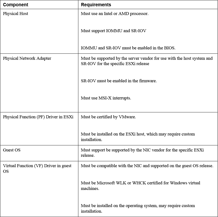
To use SR-IOV in vSphere 7.0, your environment must meet several requirements described in Table 3-5.
Table 3-5 SR-IOV Requirements
The following features are not available for SR-IOV enabled virtual machines. Attempts to configure these features may result in unexpected behavior.
![]()
• vSphere vMotion
• Storage vMotion
• vShield
• NetFlow
• VXLAN Virtual Wire
• vSphere High Availability
• vSphere Fault Tolerance
• vSphere DRS
• vSphere DPM
• Virtual machine suspend and resume
• Virtual machine snapshots
• MAC-based VLAN for passthrough virtual functions
• Hot addition and removal of virtual devices, memory, and vCPU
• Participation in a cluster environment
• Network statistics for a virtual machine NIC using SR-IOV passthrough
The following NICs are supported for virtual machines configured with SR-IOV. Each NIC must have SR-IOV supported drivers and may require SR-IOV to be enabled on the firmware.
• Products based on the Intel 82599ES 10 Gigabit Ethernet Controller Family (Niantic)
• Products based on the Intel Ethernet Controller X540 Family (Twinville)
• Products based on the Intel Ethernet Controller X710 Family (Fortville)
• Products based on the Intel Ethernet Controller XL170 Family (Fortville)
• Emulex OneConnect (BE3)
An SR-IOV NIC can operate in one of three modes in ESXi.
• Non SR-IOV Mode: the NIC is not used to provide VFs to virtual machines.
• SR-IOV Only Mode: the NIC provides VFs to virtual machines, but does not back other virtual machine traffic. In the vSphere Client, the NIC appears in a separate list (External SR-IOV Adapters) in the switch topology page.
• Mixed Mode. The NIC services virtual machines with and without SR-IOV
DirectPath I/O and SR-IOV offer similar performance benefits and tradeoffs, but you should use them to accomplish different goals. You can use SR-IOV in workloads with extremely high packet rates or very low latency requirements, where you want multiple virtual machines to share the same physical NIC (same physical function). With DirectPath I/O you can map only one physical NIC to one virtual machine.
VMkernel Networking and TCP/IP Stacks
The VMkernel networking layer provides connectivity for the hypervisor and handles system services traffic, such as management, vMotion, IP based storage, provisioning, Fault Tolerance logging, vSphere Replication, vSphere Replication NFC, and vSAN. You can create multiple VMkernel virtual network adapters to support these services. For each VMkernel adapter you can select which system service it supports. Each VMkernel adapter requires IP configuration and virtual switch configuration. You can choose to configure multiple system services to share networks or you can configure a separate network for each system service. In addition to using separate virtual and physical network infrastructure to support each system service, you can use separate VMkernel TCP/IP stacks.
The VMkernel provides multiple TCP/IP stacks that you can use to isolate the system services traffic. You can use the pre-existing stacks (default, vMotion, and Provisioning) and create custom stacks, as described here.
• Default TCP/IP Stack: This stack provides networking support for management traffic and for all VMkernel traffic types. You can choose to use just this stack and ignore the other available stacks.
• vMotion TCP/IP stack: This stack supports the traffic for vMotion. You can use this stack to improve the isolation for the vMotion traffic. After you create a VMkernel adapter on this stack, you can no longer use the default stack for vMotion (vMotion is automatically disabled on VMkernel adapters on the default stack).
• Provisioning TCP/IP stack: This stack supports the traffic for virtual machine cold migration, cloning, and snapshot migration. It also supports the Network File Copy (NFC) traffic used for cloning virtual disks during long-distance vMotion. You can use this stack to isolate provisioning traffic, placing it on a separate gateway. After you create a VMkernel adapter on this stack, you can no longer use the default stack for provisioning. (Provisioning is automatically disabled on VMkernel adapters on the default stack).
• Custom TCP/IP stack: You can create custom stacks to isolate the networking of your custom applications.
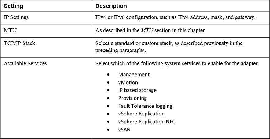
When you create a VMkernel virtual network adapter, you should configure the settings described in Table 3-6.
Table 3-6 VMkernel Adapter Settings
Exam Preparation Tasks
As mentioned in the section “How to Use This Book” in the Introduction, you have a couple of choices for exam preparation: the exercises here, Chapter 15, “Final Preparation,” and the exam simulation questions on the companion website.
Review All Key Topics
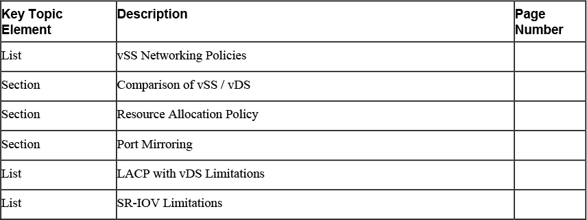
Review the most important topics in this chapter, noted with the Key Topics icon in the outer margin of the page. Table 3-7 lists a reference of these key topics and the page numbers on which each is found.
![]()
Table 3-7 Key Topics for Chapter 3
Complete the Tables and Lists from Memory
Print a copy of Appendix B, “Memory Tables” (found on the companion website), or at least the section for this chapter, and complete the tables and lists from memory. Appendix C, “Memory Tables Answer Key,” also on the companion website includes completed tables and lists to check your work.
Define Key Terms
Define the following key terms from this chapter and check your answers in the glossary:
Single Root I/O Virtualization (SR-IOV)
vSphere Distributed Switch (vDS)
Review Questions
1. You are configuring traffic shaping polices for your vSphere Standard Switch. Which one of the following is not an available setting?
a. Peak bandwidth
b. Minimum bandwidth
c. Average bandwidth
d. Burst size
2. You want to implement network security policies at the lowest available level. Which approach should you choose?
a. Use standard switches and apply policies on the individual ports
b. Use standard switches and choose override on the port groups
c. Use distributed switches and apply policies on the individual ports
d. Use distributed switches and apply policies on the distributed port groups
3. You created a distributed port group with default settings. Which one of the following statements is true?
a. The port group is set for Fixed allocation and 8 ports
b. The port group is set for Elastic allocation and 8 ports
c. The port group is set for Fixed allocation and 16 ports
d. The port group is set for Elastic allocation and 16 ports
4. You want to address an application’s sensitivity to network latency by implementing a technology that presents a physical device as multiple virtual functions. Which one of the following should you implement?
a. DirectPath I/O
b. TSO
c. LACP
d. SR-IOV
5. You want to control the use of NetFlow within your distributed switch. Which type of network policy should you implement?
a. Traffic Shaping
b. Monitoring
c. Resource Allocation
d. Filtering and marking