Chapter 16
Configure and Verify Single Area OSPFv2
This chapter ensures that you understand OSPFv2 for the CCNA 200-301 exam from Cisco Systems. It is wonderful to see Cisco Systems finally bidding farewell to RIP when it comes to dynamic routing protocol coverage in the CCNA exam. Instead, the focus now is on a very scalable, exciting, and popular modern routing protocol option: OSPF version 2. This is the OSPF version designed for IPv4.
This chapter covers the following essential terms and components:
▸ OSPFv2
▸ network command
▸ Process ID
▸ Router ID
▸ Designated router (DR)
▸ Backup designated router (BDR)
▸ Point-to-Point network type
▸ Broadcast network type
▸ Point-to-multipoint network type
▸ Non-broadcast network type
▸ Point-to-multipoint non-broadcast network type
Topic: Configure, verify, and troubleshoot single area OSPFv2 for IPv4
CramSaver
If you can correctly answer these CramSaver questions, save time by skimming the ExamAlerts in this section and then completing the CramQuiz at the end of this section and the Review Questions at the end of the chapter. If you are in doubt at all, read everything in this chapter!
1. What aspect of OSPF makes the protocol hierarchical and permits the creation of very scalable networks?
_________
2. What single OSPF router configuration command allows the assignment of OSPF area 0 to all interfaces in the range 10.0.0.0 to 10.255.255.255?
_________
Open Shortest Path First (OSPF) is a beloved link-state routing protocol that is extremely configurable and scalable. It uses areas to reduce the size of convergence domains in the topology and ensure that scalability can be maintained. Remember that a convergence domain describes the set of routers that need to update their routing information whenever there is a change within that set.
OSPF version 2 is the current IPv4-only version of OSPF. OSPF version 3 is a standard for routing either IPv4 or IPv6 or both IPv4 and IPv6 simultaneously.
Figure 16.1 shows a sample topology, and Example 16.1 shows the configuration of OSPF in a single area of this topology, using the network command.
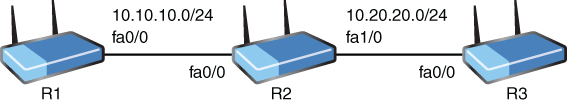
Figure 16.1 Sample OSPF Topology
Example 16.1 Configuring Single Area OSPFv2 Using the network Command
R1#
R1# configure terminal
R1(config)# router ospf 1
R1(config-router)# network 10.10.10.1 0.0.0.0 area 0
R1(config-router)# network 1.1.1.1 0.0.0.0 area 0
R1(config-router)# end
R1#
R2#
R2# configure terminal
R2(config)# router ospf 1
R2(config-router)# network 10.0.0.0 0.255.255.255 area 0
R2(config-router)# network 2.2.2.2 0.0.0.0 area 0
R2(config-router)# end
R2#
R3#
R3# configure terminal
R3(config)# router ospf 1
R3(config-router)# network 10.20.20.3 0.0.0.0 area 0
R3(config-router)# network 3.3.3.3 0.0.0.0 area 0
R3(config-router)# end
R3#
Notice the following details in the configuration in Example 16.1:
▸ router ospf 1: This command enters router configuration mode for OSPFv2 and sets a process ID of 1; this number is locally significant and does not need to match on the neighboring router.
▸ network 10.10.10.1 0.0.0.0 area 0: The network command sets the interface(s) that will run OSPF for this process; note that the wildcard mask 0.0.0.0 indicates that OSPF will run on the specific interface that has the IP address 10.10.10.1 (fa0/0); notice also that this interface participates in area 0, which is the backbone or core area for OSPF; all other areas must have contact with this backbone.
Example 16.2 shows how to easily verify OSPF.
Example 16.2 Verifying Single Area OSPF
R1#
R1# show ip ospf neighbor
Neighbor ID  Pri    State      Dead Time Address   Interface
2.2.2.2       1      FULL/BDR  00:00:37   10.10.10.2 FastEthernet0/0
R1# show ip route
Codes: L - local, C - connected, S - static, R - RIP, M - mobile, B - BGP
       D - EIGRP, EX - EIGRP external, O - OSPF, IA - OSPF inter area
       N1 - OSPF NSSA external type 1, N2 - OSPF NSSA external type 2
       E1 - OSPF external type 1, E2 - OSPF external type 2
        i - IS-IS, su - IS-IS summary, L1 - IS-IS level-1, L2 - IS-IS level-2
       ia - IS-IS inter area, * - candidate default, U - per-user static route
        o - ODR, P - periodic downloaded static route, + - replicated route

Gateway of last resort is not set

    1.0.0.0/8 is variably subnetted, 2 subnets, 2 masks
C      1.1.1.0/24 is directly connected, Loopback0
L      1.1.1.1/32 is directly connected, Loopback0
    2.0.0.0/32 is subnetted, 1 subnets
O      2.2.2.2 [110/2] via 10.10.10.2, 00:32:13, FastEthernet0/0
    3.0.0.0/32 is subnetted, 1 subnets
O      3.3.3.3 [110/3] via 10.10.10.2, 00:19:12, FastEthernet0/0
    10.0.0.0/8 is variably subnetted, 3 subnets, 2 masks
C      10.10.10.0/24 is directly connected, FastEthernet0/0
L      10.10.10.1/32 is directly connected, FastEthernet0/0
O      10.20.20.0/24 [110/2] via 10.10.10.2, 00:32:33, FastEthernet0/0
R1# ping 3.3.3.3

Type escape sequence to abort.
Sending 5, 100-byte ICMP Echos to 3.3.3.3, timeout is 2 seconds:
!!!!!
Success rate is 100 percent (5/5), round-trip min/avg/max = 20/52/64 ms
R1#
Example 16.2 includes the following commands:
▸ show ip ospf neighbor: This command permits you to verify that you have an OSPF adjacency with your neighbor(s).
▸ show ip route: This command permits you to see the OSPF learned route information.
▸ ping 3.3.3.3: This command tests for full reachability in the example; here, the R1 device is pinging an OSPF learned route from R3.
ExamAlert
Several parameters must match in order for an OSPF neighborship to form:
▸ The area ID
▸ Authentication settings
▸ Hello and dead intervals
▸ Stub flag
▸ MTU size
The hello and dead intervals are manipulated under interface configuration mode with the following commands:
(config-if)# ip ospf hello-interval 10
(config-if)# ip ospf dead-interval 30
The values used here indicate seconds.
Example 16.3 demonstrates single area OSPF configuration without the use of the network command.
Example 16.3 Configuring Single Area OSPF Without the Use of the network Command
R1#
R1# configure terminal
R1(config)# interface fa0/0
R1(config-if)# ip ospf 1 area 0
R1(config-if)# interface lo0
R1(config-if)# ip ospf 1 area 0
R1(config-if)# end
R1#
R2#
R2# configure terminal
R2(config)# interface fa0/0
R2(config-if)# ip ospf 1 area 0
R2(config-if)# interface fa1/0
R2(config-if)# ip ospf 1 area 0
R2(config-if)# interface loopback 0
R2(config-if)# ip ospf 1 area 0
R2(config-if)# end
R2#
R3#
R3# configure terminal
R3(config)# interface fa0/0
R3(config-if)# ip ospf 1 area 0
R3(config-if)# interface loopback 0
R3(config-if)# ip ospf 1 area 0
R3(config-if)# end
R3#
Notice how simple it is to configure OSPF under the appropriate interfaces. As you can see, you do not have to enter OSPF router configuration mode at all for a basic configuration.
If you examine the show ip ospf neighbor command closely, you will notice some very interesting details in the output. First, note that the neighbor ID is listed. In Example 16.2, the neighbor ID value is 2.2.2.2. This is actually the router ID value for the OSPF speaker. This value is very important for various functions in OSPF. In fact, the router ID can be used in the election process of the DR and BDR devices in certain types of OSPF network configurations. This concept is discussed later in this chapter.
You can manually set a router ID for an OSPF router by using the router-id command, or you can allow the router to self-assign this value. How does the router choose its own router ID? It follows this order:
Use the manually configured router ID (if you configured it).
Use the numerically highest IP address on a loopback interface.
Use the numerically highest IP address on a non-loopback interface.
The show ip ospf neighbor command also indicates the current state of the neighbor. If you examine the output shown in Example 16.2, you will notice the state listed as FULL/BDR.
OSPF uses the following states in its operation in order to build and maintain neighbor relationships:
▸ Down
▸ Attempt
▸ Init
▸ 2-Way
▸ Exstart
▸ Exchange
▸ Loading
▸ Full
If there is a problem with a configuration or the underlying network, you might run your neighbor verification command and learn that your OSPF routers are stuck in one of the states that was supposed to be a transition state from Down to Full. Obviously, such information can help you dramatically in your troubleshooting.
What about the BDR indication in the output in Example 16.2? This indicates that the peer router is fulfilling the role of the backup designated router (BDR). The designated router (DR) and the BDR are used in certain types of network configurations for OSPF. They try to make the operation of OSPF more efficient by reducing the number of advertisements that must be made when sharing network information. Here is a list of the network types that are possible in OSPF and whether they use a DR and BDR in the operations of the protocol:
▸ Broadcast: DR/BDR used
▸ Non-broadcast: DR/BDR used
▸ Point-to-point: No DR/BDR
▸ Point-to-multipoint: No DR/BDR
▸ Point-to-multipoint non-broadcast: No DR/BDR
CramQuiz
1. Which statement about OSPFv2 is true?
![]() A. The dead timers do not need to match between neighbors.
A. The dead timers do not need to match between neighbors.
![]() B. The hello timers do not need to match between neighbors.
B. The hello timers do not need to match between neighbors.
![]() C. The area ID must match between neighbors.
C. The area ID must match between neighbors.
![]() D. The network command must be used.
D. The network command must be used.
2. What command can you use to verify neighbors in OSPFv2?
![]() A. show ospf neighbors
A. show ospf neighbors
![]() B. show ip ospf neighbors
B. show ip ospf neighbors
![]() C. show ospf database neighbors
C. show ospf database neighbors
![]() D. show ospf peers
D. show ospf peers
CramQuiz Answers
1. C is correct. Area ID and hello and dead timers must match between neighbors.
2. B is correct. The show ip ospf neighbors command permits the verification of OSPF peerings.
Review Questions
1. What command enters router configuration mode for OSPF version 2?
![]() A. router ospf 1
A. router ospf 1
![]() B. router ospf version 2
B. router ospf version 2
![]() C. ospf router version 1
C. ospf router version 1
![]() D. router ospf process 1 version 2
D. router ospf process 1 version 2
2. You have configured OSPF on a router by using the command network 10.10.0.0 0.0.255.255 area 0. On which interface is OSPF running?
![]() A. Gi0/0: 10.0.0.1 255.255.0.0
A. Gi0/0: 10.0.0.1 255.255.0.0
![]() B. Gi0/1: 10.10.100.1 255.255.255.0
B. Gi0/1: 10.10.100.1 255.255.255.0
![]() C. Gi0/2: 10.1.10.100 255.0.0.0
C. Gi0/2: 10.1.10.100 255.0.0.0
![]() D. Gi0/3: 10.100.100.1 255.255.255.0
D. Gi0/3: 10.100.100.1 255.255.255.0
3. What does not have to match in order for an OSPF neighborship to form?
![]() A. Area ID
A. Area ID
![]() B. MTU size
B. MTU size
![]() C. Hello and dead intervals
C. Hello and dead intervals
![]() D. Use of the network command versus the ip ospf command
D. Use of the network command versus the ip ospf command
4. You have allowed a router to self-assign its router ID. What is the first option considered for the assignment on the device?
![]() A. A random router ID assignment
A. A random router ID assignment
![]() B. The IP address on the highest-numbered interface name
B. The IP address on the highest-numbered interface name
![]() C. The highest IP address on a physical interface
C. The highest IP address on a physical interface
![]() D. The highest IP address on a loopback interface
D. The highest IP address on a loopback interface
5. Which network type in OSPF features the use of a DR and a BDR?
![]() A. Point-to-point
A. Point-to-point
![]() B. Broadcast
B. Broadcast
![]() C. Point-to-multipoint
C. Point-to-multipoint
![]() D. Point-to-multipoint non-broadcast
D. Point-to-multipoint non-broadcast
Answers to Review Questions
1. A is correct. The router ospf 1 command enters router configuration mode for OSPF. It uses the local process ID 1.
2. B is correct. The network 10.10.0.0 0.0.255.255 area 0 command ensures that OSPF runs on any interfaces that have IP addresses that have 10.10 in the first two octets. This is the Gi0/1 interface in this question.
3. D is correct. Neighborships can form in OSPF if one router uses the network command and the other uses the interface-level ip ospf command. Process IDs do not need to match between routers either.
4. D is correct. If you do not manually configure a router ID, the highest IP address on a loopback interface is used as the router ID. If there are no loopback interfaces, the router uses the highest IP address on a physical interface. If OSPF cannot find a configured IPv4 address, the OSPF process does not start.
5. B is correct. The DR and BDR devices are used in the broadcast and non-broadcast network types.
Hands-On Lab Practice Assignment
Configure OSPFv2
To complete this Hands-On Lab Practice Assignment, download the assigned Packet Tracer file from the book’s companion website and perform the lab on your locally installed version of Packet Tracer. For instructions on how to download and use the Packet Tracer files, see “Packet Tracer Hands-On Lab Practice Assignments” in the Introduction of this book.
Additional Resource
Troubleshooting OSPFv2 Neighborship Formation