Chapter 2
Single-Area OSPFv2 Configuration
Objectives
Upon completion of this chapter, you will be able to answer the following questions:
How do you configure an OSPFv2 router ID?
How do you configure single-area OSPFv2 in a point-to-point network?
How do you configure the OSPF interface priority to influence the DR/BDR election in a multiaccess network?
How do you implement modifications to change the operation of single-area OSPFv2?
How do you configure OSPF to propagate a default route?
How do you verify a single-area OSPFv2 implementation?
Key Terms
This chapter uses the following key terms. You can find the definitions in the Glossary.
OSPF Hello and Dead intervals page 70
Introduction (2.0)
Now that you know about single-area OSPFv2, you can probably think of many ways it could benefit your own network. As a link-state protocol, OSPF is designed to not only find the fastest available route, it is designed to create fast, available routes. You may prefer a bit more control over some areas of your network, and OSPF gives you several ways to manually override the DR election process and create your own preferred routes. With OSPF, your network can combine the automated processes with your own choices to make a network that you could troubleshoot in your sleep! You know you want to learn how to do this!
OSPF Router ID (2.1)
In this section you will configure the OSPF router ID.
OSPF Reference Topology (2.1.1)
This section discusses the foundation on which OSPF bases its entire process: the OSPF router ID. Figure 2-1 shows the topology used for configuring OSPFv2 in this chapter.

Figure 2-1 OSPF Reference Topology
The routers in this topology have a starting configuration, including interface addresses. There is currently no static routing or dynamic routing configured on any of the routers. All interfaces on R1, R2, and R3 (except the Loopback 1 interface on R2) are within the OSPF backbone area. The ISP router is used as the gateway to the internet of the routing domain.
Note
In this topology the loopback interface is used to simulate the WAN link to the internet and a LAN connected to each router. This is done to allow this topology to be duplicated for demonstration purposes on routers that only have two Gigabit Ethernet interfaces.
Router Configuration Mode for OSPF (2.1.2)
OSPFv2 is enabled using the router ospf process-id global configuration mode command, as shown in Example 2-1 for R1. The process-id value is a number between 1 and 65,535 and is selected by the network administrator. The process-id value is locally significant, which means that it does not have to be the same value on the other OSPF routers to establish adjacencies with those neighbors. It is considered best practice to use the same process-id on all OSPF routers.
Example 2-1 OSPF Router Configuration Commands
R1(config)# router ospf 10
R1(config-router)# ?
  area                   OSPF area parameters
  auto-cost              Calculate OSPF interface cost according to bandwidth
  default-information    Control distribution of default information
  distance               Define an administrative distance
  exit                   Exit from routing protocol configuration mode
  log-adjacency-changes  Log changes in adjacency state
  neighbor               Specify a neighbor router
  network                Enable routing on an IP network
  no                     Negate a command or set its defaults
  passive-interface      Suppress routing updates on an interface
  redistribute           Redistribute information from another routing protocol
  router-id              router-id for this OSPF process
R1(config-router)#
After you enter the router ospf process-id command, the router enters router configuration mode, as indicated by the R1(config-router)# prompt. Enter a question mark (?) to view all the commands available in this mode. The list of commands shown in Example 2-1 has been altered to display only the commands that are relevant to this chapter.
Router IDs (2.1.3)
An OSPF router ID is a 32-bit value, represented as an IPv4 address. The router ID is used to uniquely identify an OSPF router. Every OSPF packet includes the router ID of the originating router. Every router requires a router ID to participate in an OSPF domain. The router ID can be defined by an administrator or automatically assigned by the router. The router ID is used by an OSPF-enabled router to do the following:
Participate in the synchronization of OSPF databases: During the Exchange state, the router with the highest router ID sends its Database Descriptor (DBD) packets first.
Participate in the election of the designated router (DR): In a multiaccess LAN environment, the router with the highest router ID is elected the DR. The routing device with the second-highest router ID is elected the backup designated router (BDR).
Note
The DR and BDR election process is discussed in more detail later in this chapter.
Router ID Order of Precedence (2.1.4)
How does a router determine the router ID? As illustrated in Figure 2-2, Cisco routers derive the router ID based on one of three criteria.
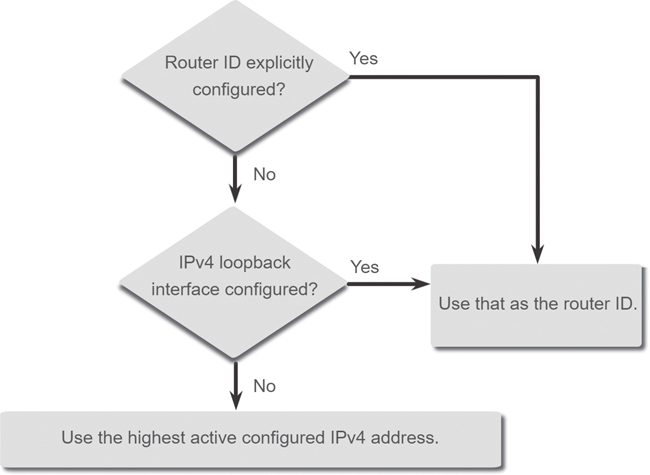
Figure 2-2 Three Criteria for Choosing the Router ID
The router ID is explicitly configured using the OSPF router-id rid router configuration mode command. The rid value is any 32-bit value expressed as an IPv4 address. This is the recommended method to assign a router ID.
If the router ID is not explicitly configured, the router chooses the highest IPv4 address of any of the configured loopback interfaces. This is the next best alternative to assigning a router ID.
If no loopback interfaces are configured, the router chooses the highest active IPv4 address of any of its physical interfaces. This is the least recommended method because it makes it more difficult for administrators to distinguish between specific routers.
Configure a Loopback Interface as the Router ID (2.1.5)
In the reference topology shown in Figure 2-1, only the physical interfaces are configured and active. The loopback interfaces have not been configured. When OSPF routing is enabled on the router, the routers pick the following highest active configured IPv4 addresses as the router IDs:
R1: 10.1.1.14 (G0/0/1)
R2: 10.1.1.9 (G0/0/1)
R3: 10.1.1.13 (G0/0/0)
Note
OSPF does not need to be enabled on an interface for that interface to be chosen as the router ID.
Instead of relying on the physical interface, the router ID can be assigned to a loopback interface. Typically, the IPv4 address for this type of loopback interface should be configured using a 32-bit subnet mask (255.255.255.255). This effectively creates a host route. A 32-bit host route would not get advertised as a route to other OSPF routers.
Example 2-2 shows how to configure a loopback interface on R1. Assuming that the router ID was not explicitly configured or previously learned, R1 uses IPv4 address 1.1.1.1 as its router ID. Assume in this case that R1 has not yet learned a router ID.
Example 2-2 Using the Loopback Address as the Router ID
R1(config-if)# interface Loopback 1
R1(config-if)# ip address 1.1.1.1 255.255.255.255
R1(config-if)# end
R1#
R1# show ip protocols | include Router ID
  Router ID 1.1.1.1
R1#
Explicitly Configure a Router ID (2.1.6)
In Figure 2-3, the topology has been updated to show the router ID for each router:
R1: 1.1.1.1
R2: 2.2.2.2
R3: 3.3.3.3
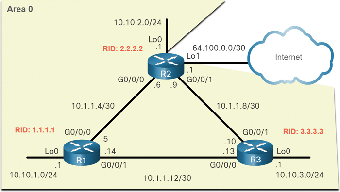
Figure 2-3 OSPF Reference Topology with Router IDs
Use the router-id rid router configuration mode command to manually assign a router ID. In Example 2-3, the router ID 1.1.1.1 is assigned to R1. Use the show ip protocols command, as shown in this example, to verify the router ID.
Example 2-3 Configuring and Verifying the Router ID
R1(config)# router ospf 10
R1(config-router)# router-id 1.1.1.1
R1(config-router)# end
*May 23 19:33:42.689: %SYS-5-CONFIG_I: Configured from console by console
R1#
R1# show ip protocols | include Router ID
  Router ID 1.1.1.1
R1#
Modify a Router ID (2.1.7)
After a router selects a router ID, an active OSPF router does not allow the router ID to be changed until the router is reloaded or the OSPF process is reset.
In Example 2-4 R1, the configured router ID has been removed and the router reloaded.
Example 2-4 Modifying the Router ID
R1# show ip protocols | include Router ID
  Router ID 10.10.1.1
R1#
R1# conf t
Enter configuration commands, one per line.  End with CNTL/Z.
R1(config)# router ospf 10
R1(config-router)# router-id 1.1.1.1
% OSPF: Reload or use "clear ip ospf process" command, for this to take effect
R1(config-router)# end
R1#
R1# clear ip ospf process
Reset ALL OSPF processes? [no]: y
*Jun  6 01:09:46.975: %OSPF-5-ADJCHG: Process 10, Nbr 3.3.3.3 on GigabitEthernet0/0/1
 from FULL to DOWN, Neighbor Down: Interface down or detached
*Jun  6 01:09:46.975: %OSPF-5-ADJCHG: Process 10, Nbr 2.2.2.2 on GigabitEthernet0/0/0
 from FULL to DOWN, Neighbor Down: Interface down or detached
*Jun  6 01:09:46.981: %OSPF-5-ADJCHG: Process 10, Nbr 3.3.3.3 on GigabitEthernet0/0/1
 from LOADING to FULL, Loading Done
*Jun  6 01:09:46.981: %OSPF-5-ADJCHG: Process 10, Nbr 2.2.2.2 on GigabitEthernet0/0/0
 from LOADING to FULL, Loading Done
R1#
R1# show ip protocols | include Router ID
  Router ID 1.1.1.1
R1#
Notice that the current router ID is 10.10.1.1, which is the Loopback 0 IPv4 address. The router ID should be 1.1.1.1. Therefore, R1 is configured with the command router-id 1.1.1.1.
Notice that an informational message appears, stating that the OSPF process must be cleared or the router must be reloaded. R1 already has adjacencies with other neighbors using the router ID 10.10.1.1, and those adjacencies must be renegotiated using the new router ID 1.1.1.1. Use the clear ip ospf process command to reset the adjacencies. You can then verify that R1 is using the new router ID with the show ip protocols command piped to display only the router ID section.
Clearing the OSPF process is the preferred method to reset the router ID.
Note
Using the router-id command is the preferred method for assigning an OSPF router ID. Otherwise, the router chooses the highest IPv4 loopback interface address or the highest active IPv4 address of any of its physical interfaces.
Syntax Checker—Configure R2 and R3 Router IDs (2.1.8)

Refer to the online course to complete this activity.
Check Your Understanding—OSPF Router ID (2.1.9)
Refer to the online course to complete this activity.
Point-to-Point OSPF Networks (2.2)
In this section, you will configure a point-to-point single-area OSPF network.
The network Command Syntax (2.2.1)
One type of network classified by OSPF is a point-to-point network. You can specify the interfaces that belong to a point-to-point network by configuring the network router configuration command. You can also configure OSPF directly on the interface with the ip ospf interface configuration command, as you will see later in this chapter. Both commands are used to determine which interfaces participate in the routing process for an OSPFv2 area.
The basic syntax for the network command is as follows:
Router(config-router)# network network-address wildcard-mask area area-id
In this syntax:
network-address wildcard-mask syntax is used to enable OSPF on interfaces. Any interfaces on a router that match the network address in the network command are enabled to send and receive OSPF packets.
area area-id refers to the OSPF area. When configuring single-area OSPFv2, the network command must be configured with the same area-id value on all routers. Although any area ID can be used, it is good practice to use an area ID of 0 with single-area OSPFv2. Following this convention makes it easier if the network is later altered to support multiarea OSPFv2.
The Wildcard Mask (2.2.2)
The wildcard mask is typically the inverse of the subnet mask configured on the interface. In a subnet mask, binary 1 indicates a match, and binary 0 is not a match. In a wildcard mask, the reverse is true, as shown here:
Wildcard mask bit 0: Matches the corresponding bit value in the address.
Wildcard mask bit 1: Ignores the corresponding bit value in the address.
The easiest method for calculating a wildcard mask is to subtract the network subnet mask from 255.255.255.255, as shown for the /24 and /26 subnet masks in Figure 2-4.
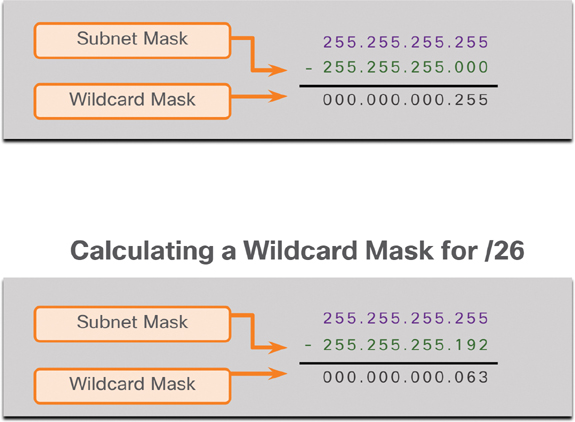
Figure 2-4 Wildcard Mask Calculation
Check Your Understanding—The Wildcard Masks (2.2.3)
Refer to the online course to complete this activity.
Configure OSPF Using the network Command (2.2.4)
Within routing configuration mode, there are two ways to identify the interfaces that will participate in the OSPFv2 routing process. Figure 2-5 shows the reference topology for this section.

Figure 2-5 OSPF Reference Topology
In Example 2-5, the wildcard mask identifies the interface based on the network addresses. Any active interface that is configured with an IPv4 address belonging to that network will participate in the OSPFv2 routing process.
Example 2-5 Wildcard Mask Based on Network Address
R1(config)# router ospf 10
R1(config-router)# network 10.10.1.0 0.0.0.255 area 0
R1(config-router)# network 10.1.1.4 0.0.0.3 area 0
R1(config-router)# network 10.1.1.12 0.0.0.3 area 0
R1(config-router)#
Note
Some IOS versions allow the subnet mask to be entered instead of the wildcard mask. IOS then converts the subnet mask to the wildcard mask format.
As an alternative, Example 2-6 shows how OSPFv2 can be enabled by specifying the exact interface IPv4 address using a quad-zero wildcard mask. Entering network 10.1.1.5 0.0.0.0 area 0 on R1 tells the router to enable interface Gigabit Ethernet 0/0/0 for the routing process. As a result, the OSPFv2 process will advertise the network that is on this interface (10.1.1.4/30).
Example 2-6 Wildcard Based on the Interface IPv4 Address
R1(config)# router ospf 10
R1(config-router)# network 10.10.1.1 0.0.0.0 area 0
R1(config-router)# network 10.1.1.5 0.0.0.0 area 0
R1(config-router)# network 10.1.1.14 0.0.0.0 area 0
R1(config-router)#
The advantage of specifying the interface is that the wildcard mask calculation is not necessary. Notice that in all cases, the area argument specifies area 0.
Syntax Checker—Configure R2 and R3 Using the network Command (2.2.5)
Refer to the online course to complete this activity.
Configure OSPF Using the ip ospf Command (2.2.6)
You can configure OSPF directly on the interface instead of by using the network command. To configure OSPF directly on the interface, use the ip ospf interface configuration mode command. The syntax is as follows:
Router(config-if)# ip ospf process-id area area-id
For R1, remove the network commands by using the no form of the network commands. Then go to each interface and configure the ip ospf command, as shown in Example 2-7.
Example 2-7 Configuring OSPF on the Interfaces
R1(config)# router ospf 10
R1(config-router)# no network 10.10.1.1 0.0.0.0 area 0
R1(config-router)# no network 10.1.1.5 0.0.0.0 area 0
R1(config-router)# no network 10.1.1.14 0.0.0.0 area 0
R1(config-router)# exit
R1(config)#
R1(config)# interface GigabitEthernet 0/0/0
R1(config-if)# ip ospf 10 area 0
R1(config-if)# exit
R1(config)#
R1(config)# interface GigabitEthernet 0/0/1
R1(config-if)# ip ospf 10 area 0
R1(config-if)# exit
R1(config)#
R1(config)# interface Loopback 0
R1(config-if)# ip ospf 10 area 0
R1(config-if)#
Syntax Checker—Configure R2 and R3 Using the ip ospf Command (2.2.7)
Refer to the online course to complete this activity.
Passive Interface (2.2.8)
By default, OSPF messages are forwarded out all OSPF-enabled interfaces. However, these messages really only need to be sent out interfaces that are connecting to other OSPF-enabled routers.
Refer to the topology in Figure 2-6.
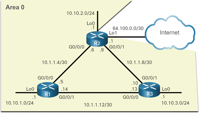
Figure 2-6 OSPF Passive Interface Reference Topology
OSPFv2 messages are forwarded out the three loopback interfaces even though no OSPFv2 neighbor exists on these simulated LANs. In a production network, these loopbacks would be physical interfaces to networks with users and traffic. Sending out unneeded messages on a LAN affects the network in three ways:
Inefficient use of bandwidth: Available bandwidth is consumed by transporting unnecessary messages.
Inefficient use of resources: All devices on the LAN must process and eventually discard the message.
Increased security risk: Without additional OSPF security configurations, OSPF messages can be intercepted with packet sniffing software. Routing updates can be modified and sent back to the router, corrupting the routing table with false metrics that misdirect traffic.
Configure Passive Interfaces (2.2.9)
Use the passive-interface router configuration mode command to prevent the transmission of routing messages through a router interface, but still allow that network to be advertised to other routers. The configuration in Example 2-8 identifies the R1 Loopback 0/0/0 interface as passive.
Example 2-8 Configuring and Verifying Passive Interfaces
R1(config)# router ospf 10
R1(config-router)# passive-interface loopback 0
R1(config-router)# end
R1#
*May 23 20:24:39.309: %SYS-5-CONFIG_I: Configured from console by console
R1#
R1# show ip protocols
*** IP Routing is NSF aware ***
(output omitted)
Routing Protocol is "ospf 10"
  Outgoing update filter list for all interfaces is not set
  Incoming update filter list for all interfaces is not set
  Router ID 1.1.1.1
  Number of areas in this router is 1. 1 normal 0 stub 0 nssa
  Maximum path: 4
  Routing for Networks:
  Routing on Interfaces Configured Explicitly (Area 0):
    Loopback0
    GigabitEthernet0/0/1
    GigabitEthernet0/0/0
  Passive Interface(s):
    Loopback0
  Routing Information Sources:
    Gateway         Distance      Last Update
    3.3.3.3              110      01:01:48
    2.2.2.2              110      01:01:38
  Distance: (default is 110)
R1#
Note
The loopback interface in this example is representing an Ethernet network. In production networks, loopback interfaces are not required to be passive.
The show ip protocols command is used to verify that the Loopback 0 interface is listed as passive. The interface is still listed under the heading “Routing on Interfaces Configured Explicitly (Area 0),” which means that this network is still included as a route entry in OSPFv2 updates that are sent to R2 and R3.
Syntax Checker—Configure R2 and R3 Passive Interfaces (2.2.10)
Use Syntax Checker to configure the loopback interfaces on R2 as passive. As an alternative, all interfaces can be made passive using the passive-interface default command. Interfaces that should not be passive can be re-enabled using the no passive-interface command. Configure R3 with the passive-interface default command and then re-enable the Gigabit Ethernet interfaces.
Refer to the online course to complete this activity.
OSPF Point-to-Point Networks (2.2.11)
By default, Cisco routers elect a DR and BDR on Ethernet interfaces, even if there is only one other device on the link. You can verify which routers have been chosen as DR or BDR using the show ip ospf interface command, as shown in Example 2-9 for G0/0/0 of R1.
Example 2-9 Verifying the OSPF Network Type
R1# show ip ospf interface GigabitEthernet 0/0/0
GigabitEthernet0/0/0 is up, line protocol is up
  Internet Address 10.1.1.5/30, Area 0, Attached via Interface Enable
  Process ID 10, Router ID 1.1.1.1, Network Type BROADCAST, Cost: 1
  Topology-MTID    Cost    Disabled    Shutdown      Topology Name
        0           1         no          no            Base
  Enabled by interface config, including secondary ip addresses
  Transmit Delay is 1 sec, State BDR, Priority 1
  Designated Router (ID) 2.2.2.2, Interface address 10.1.1.6
  Backup Designated router (ID) 1.1.1.1, Interface address 10.1.1.5
  Timer intervals configured, Hello 10, Dead 40, Wait 40, Retransmit 5
    oob-resync timeout 40
    Hello due in 00:00:08
  Supports Link-local Signaling (LLS)
  Cisco NSF helper support enabled
  IETF NSF helper support enabled
  Index 1/2/2, flood queue length 0
  Next 0x0(0)/0x0(0)/0x0(0)
  Last flood scan length is 1, maximum is 1
  Last flood scan time is 0 msec, maximum is 0 msec
  Neighbor Count is 1, Adjacent neighbor count is 1
    Adjacent with neighbor 2.2.2.2  (Designated Router)
  Suppress hello for 0 neighbor(s)
R1#
As shown in Example 2-9, in this case, R1 is the BDR and R2 is the DR. The DR/BDR election process is unnecessary as there can only be two routers on the point-to-point network between R1 and R2. Notice in this output that the router has designated the network type as BROADCAST.
To change this to a point-to-point network, use the ip ospf network point-to-point interface configuration command on all interfaces where you want to disable the DR/BDR election process. Example 2-10 shows this configuration for R1. The OSPF neighbor adjacency status will go down for a few milliseconds.
Example 2-10 Changing and Verifying the OSPF Network Type
R1(config)# interface GigabitEthernet 0/0/0
R1(config-if)# ip ospf network point-to-point
*Jun  6 00:44:05.208: %OSPF-5-ADJCHG: Process 10, Nbr 2.2.2.2 on GigabitEthernet0/0/0
  from FULL to DOWN, Neighbor Down: Interface down or detached
*Jun  6 00:44:05.211: %OSPF-5-ADJCHG: Process 10, Nbr 2.2.2.2 on GigabitEthernet0/0/0
  from LOADING to FULL, Loading Done
R1(config-if)# exit
R1(config)#
R1(config)# interface GigabitEthernet 0/0/1
R1(config-if)# ip ospf network point-to-point
*Jun  6 00:44:45.532: %OSPF-5-ADJCHG: Process 10, Nbr 3.3.3.3 on GigabitEthernet0/0/1
  from FULL to DOWN, Neighbor Down: Interface down or detached
*Jun  6 00:44:45.535: %OSPF-5-ADJCHG: Process 10, Nbr 3.3.3.3 on GigabitEthernet0/0/1
  from LOADING to FULL, Loading Done
R1(config-if)# end
R1#
R1# show ip ospf interface GigabitEthernet 0/0/0
GigabitEthernet0/0/0 is up, line protocol is up
  Internet Address 10.1.1.5/30, Area 0, Attached via Interface Enable
  Process ID 10, Router ID 1.1.1.1, Network Type POINT_TO_POINT, Cost: 1
  Topology-MTID    Cost    Disabled    Shutdown      Topology Name
        0           1         no          no            Base
  Enabled by interface config, including secondary ip addresses
  Transmit Delay is 1 sec, State POINT_TO_POINT
  Timer intervals configured, Hello 10, Dead 40, Wait 40, Retransmit 5
    oob-resync timeout 40
    Hello due in 00:00:04
  Supports Link-local Signaling (LLS)
  Cisco NSF helper support enabled
  IETF NSF helper support enabled
  Index 1/2/2, flood queue length 0
  Next 0x0(0)/0x0(0)/0x0(0)
  Last flood scan length is 1, maximum is 2
  Last flood scan time is 0 msec, maximum is 1 msec
  Neighbor Count is 1, Adjacent neighbor count is 1
    Adjacent with neighbor 2.2.2.2
  Suppress hello for 0 neighbor(s)
R1#
Notice that the Gigabit Ethernet 0/0/0 interface now lists the network type as POINT_TO_POINT and that there is no DR or BDR on the link.
Loopbacks and Point-to-Point Networks (2.2.12)
We use loopbacks to provide additional interfaces for a variety of purposes. In this case, we are using loopbacks to simulate more networks than the equipment can support. By default, loopback interfaces are advertised as /32 host routes. For example, R1 would advertise the 10.10.1.0/24 network as 10.10.1.1/32 to R2 and R3, as shown in Example 2-11.
Example 2-11 Verifying That R2 Has a Route to the R1 Loopback Interface
R2# show ip route | include 10.10.1
O        10.10.1.1/32 [110/2] via 10.1.1.5, 00:03:05, GigabitEthernet0/0/0
R2#
To simulate a real LAN, the Loopback 0 interface is configured as a point-to-point network so that R1 will advertise the full 10.10.1.0/24 network to R2 and R3, as shown in Example 2-12.
Example 2-12 Configuring the Loopback to Simulate a Point-to-Point Network
R1(config-if)# interface Loopback 0
R1(config-if)# ip ospf network point-to-point
R1(config-if)#
Now R2 receives the more accurate, simulated LAN network address of 10.10.1.0/24, as shown in Example 2-13.
Example 2-13 Verifying That R2 Now Has a /24 Route to the Loopback Network
R2# show ip route | include 10.10.1
O         10.10.1.0/24 [110/2] via 10.1.1.5, 00:00:30, GigabitEthernet0/0/0
R2#
Note
At the time of this writing, Packet Tracer does not support the ip ospf network point-to- point interface configuration command on Gigabit Ethernet interfaces. However, it does support this command on loopback interfaces.
Packet Tracer—Point-to-Point Single-Area OSPFv2 Configuration (2.2.13)

In this Packet Tracer activity, you will configure single-area OSPFv2 as follows:
Explicitly configure router IDs.
Configure the network command on R1 using a wildcard mask based on the subnet mask.
Configure the network command on R2 using a quad-zero wildcard mask.
Configure the ip ospf interface command on R3.
Configure passive interfaces.
Verify OSPF operation using the show ip protocols and show ip route commands.
Multiaccess OSPF Networks (2.3)
In this section, you will configure the OSPF interface priority to influence the DR/BDR election.
OSPF Network Types (2.3.1)
Another type of network that uses OSPF is the multiaccess OSPF network. Multiaccess OSPF networks are unique in that one router controls the distribution of LSAs. The router that is elected for this role should be determined by the network administrator through proper configuration.
OSPF may include additional processes, depending on the type of network. The topology in the previous section (refer to Figure 2-6) uses point-to-point Ethernet links between the routers. However, routers can be connected to the same switch to form a multiaccess Ethernet network, as shown in Figure 2-7.
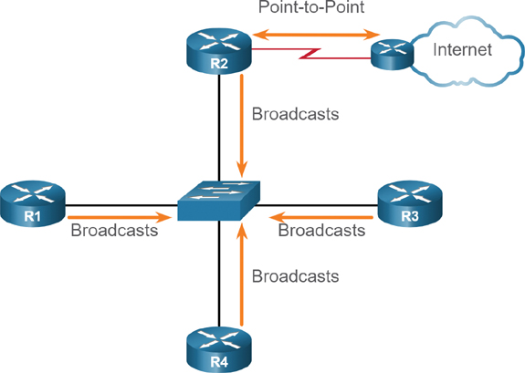
Figure 2-7 R2 Connected to Different Network Types
Ethernet LANs are the most common example of broadcast multiaccess networks. In broadcast networks, all devices on the network see all broadcast and multicast frames.
OSPF Designated Router (2.3.2)
Recall that in multiaccess networks, OSPF elects a DR and BDR as a solution to manage the number of adjacencies and the flooding of link-state advertisements (LSAs). The DR is responsible for collecting and distributing LSAs sent and received. The DR uses the multicast IPv4 address 224.0.0.5, which is meant for all OSPF routers.
A BDR is also elected in case the DR fails. The BDR listens passively and maintains a relationship with all the routers. If the DR stops producing Hello packets, the BDR promotes itself and assumes the role of DR.
Every other router becomes a DROTHER (a router that is neither the DR nor the BDR). DROTHERs use the multiaccess address 224.0.0.6 (all designated routers) to send OSPF packets to the DR and BDR. Only the DR and BDR listen for 224.0.0.6.
In Figure 2-8, R1 sends LSAs to the DR. Notice that only the DR and the BDR process the LSA sent by R1 using the multicast IPv4 address 224.0.0.6.
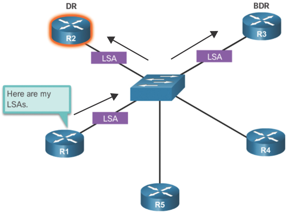
Figure 2-8 Role of the DR: Forming Adjacencies with the DR and the BDR Only
In Figure 2-9, R1, R5, and R4 are DROTHERs. The DR sends out the LSA to all OSPF routers using the multicast IPv4 address 224.0.0.5.
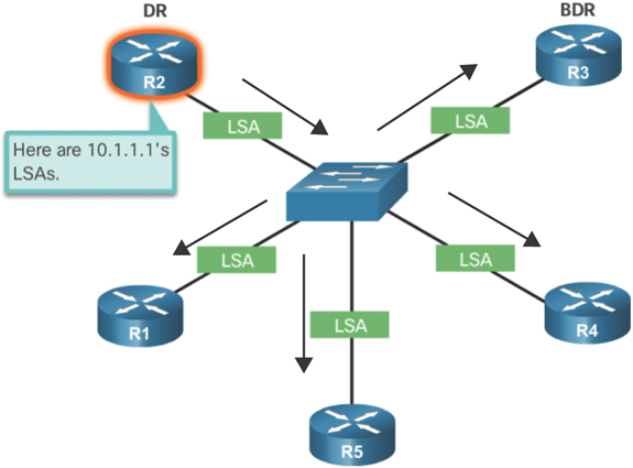
Figure 2-9 Role of the DR: Sending LSAs to Other Routers
OSPF Multiaccess Reference Topology (2.3.3)
In the multiaccess topology shown in Figure 2-10, there are three routers interconnected over a common Ethernet multiaccess network, 192.168.1.0/24.

Figure 2-10 OSPF Multiaccess Reference Topology
Each router is configured with the indicated IPv4 address on the Gigabit Ethernet 0/0/0 interface.
Because the routers are connected over a common multiaccess network, OSPF has automatically elected a DR and BDR. In this example, R3 has been elected as the DR because its router ID is 3.3.3.3, which is the highest in this network. R2 is the BDR because it has the second-highest router ID in the network.
Verify OSPF Router Roles (2.3.4)
To verify the roles of the OSPFv2 router, use the show ip ospf interface command.
R1 DROTHER
Example 2-14 shows the output of the show ip ospf interface command generated on R1.
Example 2-14 Verifying R1’s Router Role
R1# show ip ospf interface GigabitEthernet 0/0/0
GigabitEthernet0/0/0 is up, line protocol is up
  Internet Address 192.168.1.1/24, Area 0, Attached via Interface Enable
  Process ID 10, Router ID 1.1.1.1, Network Type BROADCAST, Cost: 1
  Topology-MTID    Cost    Disabled    Shutdown      Topology Name
         0           1         no           no             Base
  Enabled by interface config, including secondary ip addresses
  Transmit Delay is 1 sec, State DROTHER, Priority 1
  Designated Router (ID) 3.3.3.3, Interface address 192.168.1.3
  Backup Designated router (ID) 2.2.2.2, Interface address 192.168.1.2
  Timer intervals configured, Hello 10, Dead 40, Wait 40, Retransmit 5
    oob-resync timeout 40
    Hello due in 00:00:07
  Supports Link-local Signaling (LLS)
  Cisco NSF helper support enabled
  IETF NSF helper support enabled
  Index 1/1/1, flood queue length 0
  Next 0x0(0)/0x0(0)/0x0(0)
  Last flood scan length is 0, maximum is 1
  Last flood scan time is 0 msec, maximum is 1 msec
  Neighbor Count is 2, Adjacent neighbor count is 2
    Adjacent with neighbor 2.2.2.2  (Backup Designated Router)
    Adjacent with neighbor 3.3.3.3  (Designated Router)
  Suppress hello for 0 neighbor(s)
R1#
As shown in Example 2-14, R1 is not the DR or BDR; rather, it is a DROTHER with a default priority of 1. The DR is R3, with router ID 3.3.3.3 at IPv4 address 192.168.1.3, and the BDR is R2, with router ID 2.2.2.2 at IPv4 address 192.168.1.2. This output also shows that R1 has two adjacencies: one with the BDR and one with the DR.
R2 BDR
Example 2-15 shows the output of the show ip ospf interface command generated on R2.
Example 2-15 Verifying R2’s Router Role
R2# show ip ospf interface GigabitEthernet 0/0/0
GigabitEthernet0/0/0 is up, line protocol is up
  Internet Address 192.168.1.2/24, Area 0, Attached via Interface Enable
  Process ID 10, Router ID 2.2.2.2, Network Type BROADCAST, Cost: 1
  Topology-MTID    Cost    Disabled    Shutdown      Topology Name
         0           1           no          no            Base
  Enabled by interface config, including secondary ip addresses
  Transmit Delay is 1 sec, State BDR, Priority 1
  Designated Router (ID) 3.3.3.3, Interface address 192.168.1.3
  Backup Designated router (ID) 2.2.2.2, Interface address 192.168.1.2
  Timer intervals configured, Hello 10, Dead 40, Wait 40, Retransmit 5
    oob-resync timeout 40
    Hello due in 00:00:01
  Supports Link-local Signaling (LLS)
  Cisco NSF helper support enabled
  IETF NSF helper support enabled
  Index 1/1, flood queue length 0
  Next 0x0(0)/0x0(0)
  Last flood scan length is 0, maximum is 1
  Last flood scan time is 0 msec, maximum is 0 msec
  Neighbor Count is 2, Adjacent neighbor count is 2
    Adjacent with neighbor 1.1.1.1
    Adjacent with neighbor 3.3.3.3  (Designated Router)
  Suppress hello for 0 neighbor(s)
R2#
As shown in this example, R2 is the BDR, with a default priority of 1. The DR is R3, with router ID 3.3.3.3 at IPv4 address 192.168.1.3, and the BDR is R2, with router ID 2.2.2.2 at IPv4 address 192.168.1.2. R2 has two adjacencies: one with a neighbor with router ID 1.1.1.1 (R1) and the other with the DR.
R3 DR
Example 2-16 shows the output of the show ip ospf interface command generated by R3.
Example 2-16 Verifying R3’s Router Role
R3# show ip ospf interface GigabitEthernet 0/0/0
GigabitEthernet0/0/0 is up, line protocol is up
  Internet Address 192.168.1.3/24, Area 0, Attached via Interface Enable
  Process ID 10, Router ID 3.3.3.3, Network Type BROADCAST, Cost: 1
  Topology-MTID    Cost    Disabled    Shutdown      Topology Name
        0           1          no           no            Base
  Enabled by interface config, including secondary ip addresses
  Transmit Delay is 1 sec, State DR, Priority 1
  Designated Router (ID) 3.3.3.3, Interface address 192.168.1.3
  Backup Designated router (ID) 2.2.2.2, Interface address 192.168.1.2
  Timer intervals configured, Hello 10, Dead 40, Wait 40, Retransmit 5
    oob-resync timeout 40
    Hello due in 00:00:06
  Supports Link-local Signaling (LLS)
  Cisco NSF helper support enabled
  IETF NSF helper support enabled
  Index 1/1/1, flood queue length 0
  Next 0x0(0)/0x0(0)/0x0(0)
  Last flood scan length is 2, maximum is 2
  Last flood scan time is 0 msec, maximum is 0 msec
  Neighbor Count is 2, Adjacent neighbor count is 2
    Adjacent with neighbor 1.1.1.1
    Adjacent with neighbor 2.2.2.2  (Backup Designated Router)
  Suppress hello for 0 neighbor(s)
R3#
As shown in this example, R3 is the DR, with a default priority of 1 and router ID 3.3.3.3 at IPv4 address 192.168.1.3, and the BDR is R2, with router ID 2.2.2.2 at IPv4 address 192.168.1.2. R3 has two adjacencies: one with a neighbor with router ID 1.1.1.1 (R1) and the other with the BDR.
Verify DR/BDR Adjacencies (2.3.5)
To verify the OSPFv2 adjacencies, use the show ip ospf neighbor command. The state of neighbors in multiaccess networks can be as follows:
FULL/DROTHER: This is a DR or BDR router that is fully adjacent with a non-DR or BDR router. These two neighbors can exchange Hello packets, updates, queries, replies, and acknowledgments.
FULL/DR: The router is fully adjacent with the indicated DR neighbor. These two neighbors can exchange Hello packets, updates, queries, replies, and acknowledgments.
FULL/BDR: The router is fully adjacent with the indicated BDR neighbor. These two neighbors can exchange Hello packets, updates, queries, replies, and acknowledgments.
2-WAY/DROTHER: The non-DR or BDR router has a neighbor relationship with another non-DR or BDR router. These two neighbors exchange Hello packets.
The normal state for an OSPF router is usually FULL. If a router is stuck in another state, it is an indication that there are problems in forming adjacencies. The only exception to this is the 2-WAY state, which is normal in a multiaccess broadcast network. For example, DROTHERs form a 2-WAY neighbor adjacency with any DROTHERs that join the network. When this happens, the neighbor state displays as 2-WAY/DROTHER.
The following sections show the output for the show ip ospf neighbor command on each router.
R1 Adjacencies
In Example 2-17, the output generated by R1 confirms that R1 has adjacencies with the following routers:
R2 with router ID 2.2.2.2 is in a FULL state, and the role of R2 is BDR.
R3 with router ID 3.3.3.3 is in a FULL state, and the role of R3 is DR.
Example 2-17 R1’s Neighbor Table
R1# show ip ospf neighbor
Neighbor ID    Pri   State      Dead Time    Address       Interface
2.2.2.2          1   FULL/BDR   00:00:31     192.168.1.2    GigabitEthernet0/0/0
3.3.3.3          1   FULL/DR    00:00:39     192.168.1.3    GigabitEthernet0/0/0
R1#
R2 Adjacencies
In Example 2-18, the output generated by R2 confirms that R2 has adjacencies with the following routers:
R1 with router ID 1.1.1.1 is in a FULL state, and R1 is neither the DR nor the BDR.
R3 with router ID 3.3.3.3 is in a FULL state, and the role of R3 is DR.
Example 2-18 R2’s Neighbor Table
R2# show ip ospf neighbor
Neighbor ID    Pri   State          Dead Time  Address       Interface
1.1.1.1          1   FULL/DROTHER   00:00:31   192.168.1.1   GigabitEthernet0/0/0
3.3.3.3          1   FULL/DR        00:00:34   192.168.1.3   GigabitEthernet0/0/0
R2#
R3 Adjacencies
In Example 2-19, the output generated by R3 confirms that R3 has adjacencies with the following routers:
R1 with router ID 1.1.1.1 is in a FULL state, and R1 is neither the DR nor the BDR.
R2 with router ID 2.2.2.2 is in a FULL state, and the role of R2 is BDR.
Example 2-19 R3’s Neighbor Table
R3# show ip ospf neighbor
Neighbor ID    Pri   State          Dead Time  Address       Interface
1.1.1.1          1   FULL/DROTHER   00:00:37   192.168.1.1   GigabitEthernet0/0/0
2.2.2.2          1   FULL/BDR       00:00:33   192.168.1.2   GigabitEthernet0/0/0
R3#
Default DR/BDR Election Process (2.3.6)
How do the DR and BDR get elected? The OSPF DR and BDR election decision is based on the several criteria.
The routers in the network elect the router with the highest interface priority as the DR. The router with the second-highest interface priority is elected as the BDR. The priority can be configured to be any number between 0 and 255. If the interface priority value is set to 0, that interface cannot be elected as DR or as BDR. The default priority of multiaccess broadcast interfaces is 1. Therefore, unless otherwise configured, all routers have an equal priority value and must rely on another tie-breaking method during the DR/BDR election.
If the interface priorities are equal, then the router with the highest router ID is elected the DR. The router with the second-highest router ID is the BDR.
Recall that the router ID is determined in one of the following three ways:
The router ID can be manually configured.
If no router IDs are configured, the router ID is determined by the highest loop-back IPv4 address.
If no loopback interfaces are configured, the router ID is determined by the highest active IPv4 address.
In Figure 2-11, all Ethernet router interfaces have a default priority of 1.
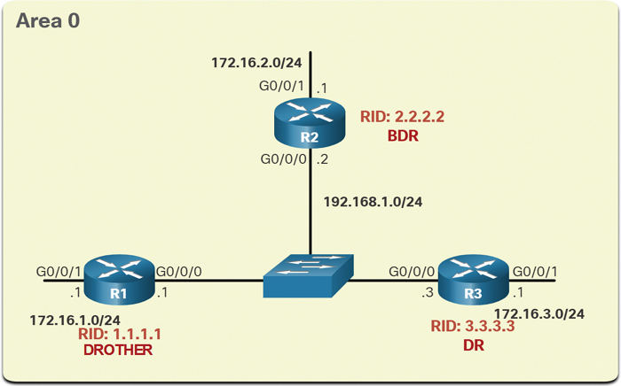
Figure 2-11 OSPF Multiaccess Reference Topology
As a result, based on the selection criteria listed above, the OSPF router ID is used to elect the DR and BDR. R3, with the highest router ID, becomes the DR; and R2, with the second-highest router ID, becomes the BDR.
The DR and BDR election process takes place as soon as the first router with an OSPF-enabled interface is active on the multiaccess network. This can happen when the preconfigured OSPF routers are powered on or when OSPF is activated on the interface. The election process takes only a few seconds. If all of the routers on the multiaccess network have not finished booting, it is possible for a router with a lower router ID to become the DR.
OSPF DR and BDR elections are not preemptive. That is, if a new router with a higher priority or higher router ID is added to the network after the DR and BDR election, the newly added router does not take over the DR or the BDR role. This is because those roles have already been assigned. The addition of a new router does not initiate a new election process.
DR Failure and Recovery (2.3.7)
After the DR is elected, it remains the DR until one of the following events occurs:
The DR fails.
The OSPF process on the DR fails or is stopped.
The multiaccess interface on the DR fails or is shut down.
If the DR fails, the BDR is automatically promoted to DR. This is the case even if another DROTHER with a higher priority or router ID is added to the network after the initial DR/BDR election. However, after a BDR is promoted to DR, a new BDR election occurs, and the DROTHER with the highest priority or router ID is elected as the new BDR.
The following sections describe various scenarios related to the DR and BDR election process.
R3 Fails
In Figure 2-12, the current DR (R3) fails.
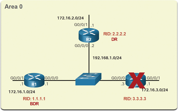
Figure 2-12 R3 Fails
Therefore, the pre-elected BDR (R2) assumes the role of DR. Subsequently, an election is held to choose a new BDR. Because R1 is the only DROTHER, it is elected as the BDR.
R3 Rejoins Network
In Figure 2-13, R3 has rejoined the network after several minutes of being unavailable.
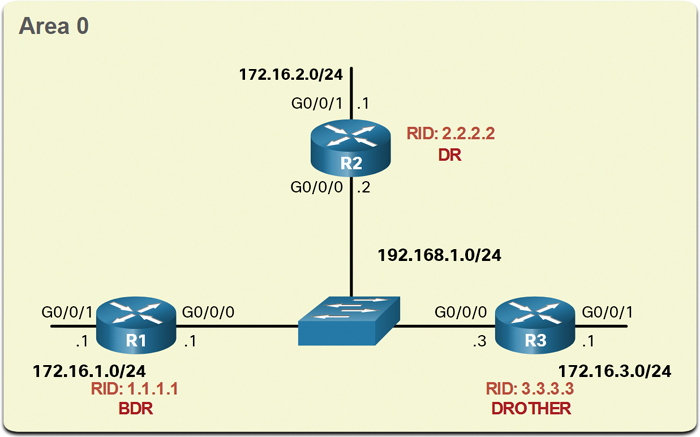
Figure 2-13 R3 Rejoins Network
Because the DR and BDR already exist, R3 does not take over either role. Instead, it becomes a DROTHER.
R4 Joins Network
In Figure 2-14, a new router (R4) with a higher router ID is added to the network.
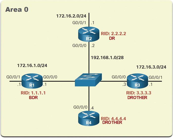
Figure 2-14 R4 Joins Network
The DR (R2) and the BDR (R1) retain the DR and BDR roles. R4 automatically becomes a DROTHER.
R2 Fails
In Figure 2-15, R2 has failed.

Figure 2-15 R2 Fails
The BDR (R1) automatically becomes the DR, and an election process selects R4 as the BDR because it has the higher router ID.
The ip ospf priority Command (2.3.8)
If the interface priorities are equal on all routers, the router with the highest router ID is elected the DR. It is possible to configure the router ID to manipulate the DR/BDR election. However, this process works only if there is a stringent plan for setting the router ID on all routers. Configuring the router ID can help control this. However, in large networks, this can be cumbersome.
Instead of relying on the router ID, it is better to control the election by setting interface priorities. This also allows a router to be the DR in one network and a DROTHER in another. To set the priority of an interface, use the ip ospf priority value interface configuration command, where value is 0 to 255. A value of 0 does not become a DR or a BDR. A value of 1 to 255 on the interface makes it more likely that the router becomes the DR or the BDR.
Configure OSPF Priority (2.3.9)
In the reference topology in Figure 2-11, the ip ospf priority interface configuration command will be used to change the DR and BDR as follows:
R1 should be the DR and will be configured with a priority of 255.
R2 should be the BDR and will be left with the default priority of 1.
R3 should never be a DR or BDR and will be configured with a priority of 0.
Example 2-20 shows a change of the R1 G0/0/0 interface priority from 1 to 255.
Example 2-20 Configuring R1’s OSPF Priority
R1(config)# interface GigabitEthernet 0/0/0
R1(config-if)# ip ospf priority 255
R1(config-if)# end
R1#
Example 2-21 shows a change of the R3 G0/0/0 interface priority from 1 to 0.
Example 2-21 Configuring R3’s OSPF Priority
R3(config)# interface GigabitEthernet 0/0/0
R3(config-if)# ip ospf priority 0
R3(config-if)# end
R3#
Example 2-22 shows how to clear the OSPF process on R1. The clear ip ospf process privileged EXEC command also must be entered on R2 and R3 (not shown). Notice the OSPF state information that is generated.
Example 2-22 Clearing OSPF on R1
R1# clear ip ospf process
Reset ALL OSPF processes? [no]: y
R1#
*Jun  5 03:47:41.563: %OSPF-5-ADJCHG: Process 10, Nbr 2.2.2.2 on GigabitEthernet0/0/0
  from FULL to DOWN, Neighbor Down: Interface down or detached
*Jun  5 03:47:41.563: %OSPF-5-ADJCHG: Process 10, Nbr 3.3.3.3 on GigabitEthernet0/0/0
  from FULL to DOWN, Neighbor Down: Interface down or detached
*Jun  5 03:47:41.569: %OSPF-5-ADJCHG: Process 10, Nbr 2.2.2.2 on GigabitEthernet0/0/0
  from LOADING to FULL, Loading Done
*Jun  5 03:47:41.569: %OSPF-5-ADJCHG: Process 10, Nbr 3.3.3.3 on GigabitEthernet0/0/0
  from LOADING to FULL, Loading Done
In Example 2-23, the output from the show ip ospf interface g0/0/0 command on R1 confirms that R1 is now the DR, with a priority of 255, and identifies the new neighbor adjacencies of R1.
Example 2-23 Verifying That R1 Is Now the DR
R1# show ip ospf interface GigabitEthernet 0/0/0
GigabitEthernet0/0/0 is up, line protocol is up
  Internet Address 192.168.1.1/24, Area 0, Attached via Interface Enable
  Process ID 10, Router ID 1.1.1.1, Network Type BROADCAST, Cost: 1
  Topology-MTID    Cost    Disabled    Shutdown      Topology Name
        0            1          no          no             Base
  Enabled by interface config, including secondary ip addresses
  Transmit Delay is 1 sec, State DR, Priority 255
  Designated Router (ID) 1.1.1.1, Interface address 192.168.1.1
  Backup Designated router (ID) 2.2.2.2, Interface address 192.168.1.2
  Timer intervals configured, Hello 10, Dead 40, Wait 40, Retransmit 5
    oob-resync timeout 40
    Hello due in 00:00:00
  Supports Link-local Signaling (LLS)
  Cisco NSF helper support enabled
  IETF NSF helper support enabled
  Index 1/1/1, flood queue length 0
  Next 0x0(0)/0x0(0)/0x0(0)
  Last flood scan length is 1, maximum is 2
  Last flood scan time is 0 msec, maximum is 1 msec
  Neighbor Count is 2, Adjacent neighbor count is 2
    Adjacent with neighbor 2.2.2.2  (Backup Designated Router)
    Adjacent with neighbor 3.3.3.3
  Suppress hello for 0 neighbor(s)
R1#
Syntax Checker—Configure OSPF Priority (2.3.10)
Refer to the online course to complete this activity.
Packet Tracer—Determine the DR and BDR (2.3.11)
In this activity, you will complete the following:
Examine the DR and BDR roles and watch the roles change when there is a change in the network.
Modify the priority to control the roles and force a new election.
Verify that routers are filling the desired roles.
Modify Single-Area OSPFv2 (2.4)
In this section, you will learn how OSPF uses cost to determine the best path and see how to configure OSPF interface settings to improve network performance.
Cisco OSPF Cost Metric (2.4.1)
Recall that a routing protocol uses a metric to determine the best path of a packet across a network. A metric gives an indication of the overhead that is required to send packets across a certain interface. OSPF uses cost as a metric. A lower cost indicates a better path than a higher cost.
Note
The OSPF RFC does not specify what “cost” is. Cisco uses the cumulative bandwidth for route calculations.
The Cisco cost of an interface is inversely proportional to the bandwidth of the interface. Therefore, a higher bandwidth indicates a lower cost. The formula used to calculate the OSPF cost is
Cost = reference bandwidth / interface bandwidth
The default reference bandwidth is 108 (100,000,000); therefore, the formula is
Cost = 100,000,000 bps / interface bandwidth in bps
The table in Figure 2-16 breaks down the cost calculation.
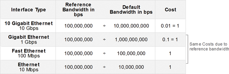
Figure 2-16 Default Cisco OSPF Costs
Because the OSPF cost value must be an integer, FastEthernet, Gigabit Ethernet, and 10 Gigabit Ethernet (10GigE) interfaces share the same cost. To correct this situation, you can:
Adjust the reference bandwidth with the auto-cost reference-bandwidth router configuration command on each OSPF router.
Manually set the OSPF cost value with the ip ospf cost interface configuration command on necessary interfaces.
Adjust the Reference Bandwidth (2.4.2)
The cost value must be an integer. If something less than an integer is calculated, OSPF rounds up to the nearest integer. Therefore, the OSPF cost assigned to a Gigabit Ethernet interface with the default reference bandwidth of 100,000,000 bps would equal 1 because the nearest integer for 0.1 is 0 instead of 1:
Cost = 100,000,000 bps / 1,000,000,000 = 1
For this reason, all interfaces faster than Fast Ethernet have the same cost value (1) as a Fast Ethernet interface. To assist OSPF in making the correct path determination, the reference bandwidth must be changed to a higher value to accommodate networks with links faster than 100 Mbps. Changing the reference bandwidth does not actually affect the bandwidth capacity on the link; rather, it simply affects the calculation used to determine the metric. To adjust the reference bandwidth, use the auto-cost reference-bandwidth Mbps router configuration command:
Router(config-router)# auto-cost reference-bandwidth Mbps
This command must be configured on every router in the OSPF domain. Notice that the value is expressed in Mbps; therefore, to adjust the costs for Gigabit Ethernet, use the auto-cost reference-bandwidth 1000 router configuration command. For 10 Gigabit Ethernet, use the auto-cost reference-bandwidth 10000 router configuration command. To return to the default reference bandwidth, use the auto-cost reference-bandwidth 100 command.
Whichever method is used, it is important to apply the configuration to all routers in the OSPF routing domain. Table 2-1 shows the OSPF cost if the reference bandwidth is adjusted to accommodate 10 Gigabit Ethernet links. The reference bandwidth should be adjusted any time there are links faster than FastEthernet (100 Mbps).
Table 2-1 OSPF Reference Bandwidths and Costs
Interface Type |
Reference Bandwidth in bps |
|
Default Bandwidth in bps |
Cost |
10 Gigabit Ethernet |
10,000,000,000 |
÷ |
10,000,000,000 |
1 |
Gigabit Ethernet |
10,000,000,000 |
÷ |
1,000,000,000 |
10 |
Fast Ethernet |
10,000,000,000 |
÷ |
100,000,000 |
100 |
Ethernet 10 Mbps |
10,000,000,000 |
÷ |
10,000,000 |
1000 |
Use the show ip ospf interface g0/0/0 command to verify the current OSPFv2 cost assigned to the R1 Gigabit Ethernet 0/0/0 interface. In Example 2-24, notice that the output displays a cost of 1. Then, after adjusting the reference bandwidth, the cost is 10. This allows for scaling to 10 Gigabit Ethernet interfaces in the future without having to adjust the reference bandwidth again.
Note
The auto-cost reference-bandwidth command must be configured consistently on all routers in the OSPF domain to ensure accurate route calculations.
Example 2-24 Configuring and Verifying R1’s Reference Bandwidth
R1# show ip ospf interface gigabitethernet0/0/0
GigabitEthernet0/0/0 is up, line protocol is up
  Internet Address 10.1.1.5/30, Area 0, Attached via Interface Enable
  Process ID 10, Router ID 1.1.1.1, Network Type POINT_TO_POINT, Cost: 1
(output omitted)
R1# config t
Enter configuration commands, one per line.  End with CNTL/Z.
R1(config)# router ospf 10
R1(config-router)# auto-cost reference-bandwidth 10000
% OSPF: Reference bandwidth is changed.
        Please ensure reference bandwidth is consistent across all routers.
R1(config-router)#
R1(config-router)# do show ip ospf interface gigabitethernet0/0/0
GigabitEthernet0/0 is up, line protocol is up
  Internet address is 172.16.1.1/24, Area 0
  Process ID 10, Router ID 1.1.1.1, Network Type BROADCAST, Cost: 10
  Transmit Delay is 1 sec, State DR, Priority 1
(output omitted)
OSPF Accumulates Costs (2.4.3)
The cost of an OSPF route is the accumulated value from one router to the destination network. Assuming that the auto-cost reference-bandwidth 10000 command has been configured on all three routers, the cost of the links between each pair of routers is now 10. The loopback interfaces have a default cost of 1, as shown in Figure 2-17.
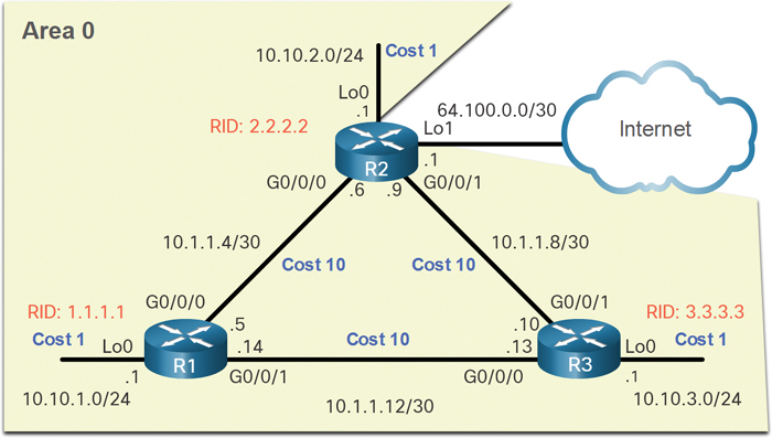
Figure 2-17 OSPF Reference Topology with Cost Values
Therefore, we can calculate the cost for each router to reach each network. For example, the total cost for R1 to reach the 10.10.2.0/24 network is 11. This is because the link to R2 cost is 10, and the loopback default cost is 1, and 10 + 1 = 11.
The routing table of R1 in Example 2-25 confirms that the metric to reach the R2 LAN is a cost of 11.
Example 2-25 Verifying R1’s Metric
R1# show ip route | include 10.10.2.0
O        10.10.2.0/24 [110/11] via 10.1.1.6, 01:05:02, GigabitEthernet0/0/0
R1#
R1# show ip route 10.10.2.0
Routing entry for 10.10.2.0/24
  Known via "ospf 10", distance 110, metric 11, type intra area
  Last update from 10.1.1.6 on GigabitEthernet0/0/0, 01:05:13 ago
  Routing Descriptor Blocks:
  * 10.1.1.6, from 2.2.2.2, 01:05:13 ago, via GigabitEthernet0/0/0
       Route metric is 11, traffic share count is 1
R1#
Manually Set OSPF Cost Value (2.4.4)
OSPF cost values can be manipulated to influence the route chosen by OSPF. For example, in the current configuration, R1 is load balancing to the 10.1.1.8/30 network. It will send some traffic to R2 and some traffic to R3. You can see this in the routing table in Example 2-26.
Example 2-26 R1: Load Balancing Traffic to 10.1.1.8/30
R1# show ip route ospf | begin 10
      10.0.0.0/8 is variably subnetted, 9 subnets, 3 masks
O        10.1.1.8/30 [110/20] via 10.1.1.13, 00:54:50, GigabitEthernet0/0/1
                     [110/20] via 10.1.1.6, 00:55:14, GigabitEthernet0/0/0
(output omitted)
R1#
Note
Changing the cost of links may have undesired consequences. Therefore, interface cost values should be adjusted only when the outcome is fully understood.
An administrator may want traffic to go through R2 and use R3 as a backup route in case the link between R1 and R2 goes down.
Another reason to change the cost value is that other vendors may calculate OSPF in a different manner. By manipulating the cost value, the administrator can make sure the route costs shared between OSPF multivendor routers are accurately reflected in routing tables.
To change the cost value reported by the local OSPF router to other OSPF routers, use the ip ospf cost value interface configuration command. In Figure 2-18, we need to change the cost of the loopback interfaces to 10 to simulate Gigabit Ethernet speeds. In addition, we will change the cost of the link between R2 and R3 to 30 so that this link is used as a backup link.
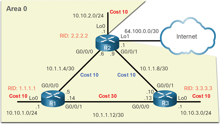
Figure 2-18 OSPF Reference Topology with Manually Adjusted Cost Values
Example 2-27 shows the configuration for R1.
Example 2-27 Cost Configuration on R1
R1(config)# interface g0/0/1
R1(config-if)# ip ospf cost 30
R1(config-if)# interface lo0
R1(config-if)# ip ospf cost 10
R1(config-if)# end
R1#
Assuming that OSPF costs for R2 and R3 have been configured to match the topology in Figure 2-18, the OSPF routes for R1 would have the cost values shown in Example 2-28. Notice that R1 is no longer load balancing to the 10.1.1.8/30 network. In fact, all routes go through R2 via 10.1.1.6, as desired by the network administrator.
Example 2-28 R1’s OSPF Cost Values
R1# show ip route ospf | begin 10
      10.0.0.0/8 is variably subnetted, 9 subnets, 3 masks
O        10.1.1.8/30 [110/20] via 10.1.1.6, 01:18:25, GigabitEthernet0/0/0
O        10.10.2.0/24 [110/20] via 10.1.1.6, 00:04:31, GigabitEthernet0/0/0
O        10.10.3.0/24 [110/30] via 10.1.1.6, 00:03:21, GigabitEthernet0/0/0
R1#
Note
Although using the ip ospf cost interface configuration command is the recommended method to manipulate the OSPF cost values, an administrator could also manipulate the values by using the bandwidth kbps interface configuration command. However, that would work only if all the routers are Cisco routers.
Test Failover to Backup Route (2.4.5)
What happens if the link between R1 and R2 goes down? We can simulate that by shutting down the Gigabit Ethernet 0/0/0 interface and verifying that the routing table is updated to use R3 as the next-hop router. In Example 2-29, notice that R1 can now reach the 10.1.1.4/30 network via 10.1.1.13 through R3, with a cost value of 50.
Example 2-29 Simulating Failover to the Backup Route
R1(config)# interface g0/0/0
R1(config-if)# shutdown
*Jun  7 03:41:34.866: %OSPF-5-ADJCHG: Process 10, Nbr 2.2.2.2 on GigabitEthernet0/0/0
  from FULL to DOWN, Neighbor Down: Interface down or detached
*Jun  7 03:41:36.865: %LINK-5-CHANGED: Interface GigabitEthernet0/0/0, changed state
  to administratively down
*Jun  7 03:41:37.865: %LINEPROTO-5-UPDOWN: Line protocol on Interface GigabitEther-
  net0/0/0, changed state to down
R1(config-if)# end
R1#
R1# show ip route ospf | begin 10
      10.0.0.0/8 is variably subnetted, 8 subnets, 3 masks
O        10.1.1.4/30 [110/50] via 10.1.1.13, 00:00:14, GigabitEthernet0/0/1
O        10.1.1.8/30 [110/40] via 10.1.1.13, 00:00:14, GigabitEthernet0/0/1
O        10.10.2.0/24 [110/50] via 10.1.1.13, 00:00:14, GigabitEthernet0/0/1
O        10.10.3.0/24 [110/40] via 10.1.1.13, 00:00:14, GigabitEthernet0/0/1
R1#
Syntax Checker—Modify the Cost Values for R2 and R3 (2.4.6)
Refer to the online course to complete this activity.
Hello Packet Intervals (2.4.7)
As shown in Figure 2-19, OSPFv2 Hello packets are transmitted to multicast address 224.0.0.5 (all OSPF routers) every 10 seconds. This is the default timer value on multiaccess and point-to-point networks.
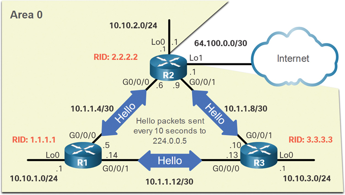
Figure 2-19 OSPF Reference Topology with Hello Packets
Note
Hello packets are not sent on the simulated LAN interfaces because those interfaces were set to passive by using the passive-interface router configuration command.
The Dead interval is the period that the router waits to receive a Hello packet before declaring the neighbor down. If the Dead interval expires before the routers receive a Hello packet, OSPF removes that neighbor from its link-state database (LSDB). The router floods the LSDB with information about the down neighbor out all OSPF-enabled interfaces. Cisco uses a default of 4 times the Hello interval. This is 40 seconds on multiaccess and point-to-point networks.
Note
On nonbroadcast multiaccess (NBMA) networks, the default Hello interval is 30 seconds, and the default Dead interval is 120 seconds. NBMA networks are beyond the scope of this chapter.
Verify Hello and Dead Intervals (2.4.8)
The OSPF Hello and Dead intervals are configurable on a per-interface basis. The OSPF intervals must match, or a neighbor adjacency does not occur. To verify the currently configured OSPFv2 interface intervals, use the show ip ospf interface command, as shown in Example 2-30. The Gigabit Ethernet 0/0/0 Hello and Dead intervals are set to the default 10 seconds and 40 seconds, respectively.
Example 2-30 Hello and Dead Intervals on R1 G0/0/0
R1# show ip ospf interface g0/0/0
GigabitEthernet0/0/0 is up, line protocol is up
  Internet Address 10.1.1.5/30, Area 0, Attached via Interface Enable
  Process ID 10, Router ID 1.1.1.1, Network Type POINT_TO_POINT, Cost: 10
  Topology-MTID    Cost    Disabled    Shutdown      Topology Name
        0            10         no          no             Base
  Enabled by interface config, including secondary ip addresses
  Transmit Delay is 1 sec, State POINT_TO_POINT
  Timer intervals configured, Hello 10, Dead 40, Wait 40, Retransmit 5
    oob-resync timeout 40
    Hello due in 00:00:06
  Supports Link-local Signaling (LLS)
  Cisco NSF helper support enabled
  IETF NSF helper support enabled
  Index 1/2/2, flood queue length 0
  Next 0x0(0)/0x0(0)/0x0(0)
  Last flood scan length is 1, maximum is 1
  Last flood scan time is 0 msec, maximum is 0 msec
  Neighbor Count is 1, Adjacent neighbor count is 1
    Adjacent with neighbor 2.2.2.2
  Suppress hello for 0 neighbor(s)
R1#
Use the show ip ospf neighbor command to see the Dead Time counting down from 40 seconds, as shown in Example 2-31. By default, this value is refreshed every 10 seconds when R1 receives a Hello from the neighbor.
Example 2-31 Dead Intervals Counting Down on R1
R1# show ip ospf neighbor
Neighbor ID     Pri   State     Dead Time    Address       Interface
3.3.3.3           0   FULL/ -   00:00:35     10.1.1.13     GigabitEthernet0/0/1
2.2.2.2           0   FULL/ -   00:00:31     10.1.1.6      GigabitEthernet0/0/0
R1#
Modify OSPFv2 Intervals (2.4.9)
It may be desirable to change the OSPF timers so that routers detect network failures in less time. Doing this increases traffic, but sometimes quick convergence is more important than the extra traffic it creates.
Note
The default Hello and Dead intervals are based on best practices and should be altered only in rare situations.
OSPFv2 Hello and Dead intervals can be modified manually using the following interface configuration mode commands:
Router(config-if)# ip ospf hello-interval seconds
Router(config-if)# ip ospf dead-interval seconds
Use the no ip ospf hello-interval and no ip ospf dead-interval commands to reset the intervals to their defaults.
In Example 2-32, the Hello interval for the link between R1 and R2 is changed to 5 seconds. Immediately after changing the Hello interval, Cisco IOS automatically modifies the Dead interval to four times the Hello interval. However, you can document the new Dead interval in the configuration by manually setting it to 20 seconds, as shown.
As displayed by the highlighted OSPFv2 adjacency message, when the Dead timer on R1 expires, R1 and R2 lose adjacency. This occurs because the R1 and R2 must be configured with the same Hello interval. Use the show ip ospf neighbor command on R1 to verify the neighbor adjacencies. Notice that the only neighbor listed is the 3.3.3.3 (R3) router and that R1 is no longer adjacent with the 2.2.2.2 (R2) neighbor.
Example 2-32 Modified Hello and Dead Intervals on R1 Causing a Loss in Adjacency with R2
R1(config)# interface g0/0/0
R1(config-if)# ip ospf hello-interval 5
R1(config-if)# ip ospf dead-interval 20
R1(config-if)#
*Jun  7 04:56:07.571: %OSPF-5-ADJCHG: Process 10, Nbr 2.2.2.2 on GigabitEthernet0/0/0
  from FULL to DOWN, Neighbor Down: Dead timer expired
R1(config-if)# end
R1#
R1# show ip ospf neighbor
Neighbor ID     Pri   State      Dead Time  Address         Interface
3.3.3.3           0   FULL/  -   00:00:37   10.1.1.13       GigabitEthernet0/0/1
R1#
To restore adjacency between R1 and R2, the R2 Gigabit Ethernet 0/0/0 interface Hello interval is set to 5 seconds, as shown in Example 2-33. Almost immediately, the IOS displays a message that adjacency has been established with a state of FULL. Verify the interface intervals by using the show ip ospf interface command. Notice that the Hello time is 5 seconds and that the Dead Time was automatically set to 20 seconds instead of the default 40 seconds.
Example 2-33 Adjusting the Hello Interval to Restore Adjacency with R2
R2(config)# interface g0/0/0
R2(config-if)# ip ospf hello-interval 5
*Jun  7 15:08:30.211: %OSPF-5-ADJCHG: Process 10, Nbr 1.1.1.1 on GigabitEthernet0/0/0
  from LOADING to FULL, Loading Done
R2(config-if)# end
R2#
R2# show ip ospf interface g0/0/0 | include Timer
  Timer intervals configured, Hello 5, Dead 20, Wait 20, Retransmit 5
R2#
R2# show ip ospf neighbor
Neighbor ID     Pri   State       Dead Time   Address       Interface
3.3.3.3           0   FULL/  -    00:00:38    10.1.1.10      GigabitEthernet0/0/1
1.1.1.1           0   FULL/  -    00:00:17    10.1.1.5      GigabitEthernet0/0/0
R2#
Syntax Checker—Modifying Hello and Dead Intervals on R3 (2.4.10)
The Hello and Dead intervals are set to 5 and 20, respectively, on R1 and R2. Use Syntax Checker to modify the Hello and Dead intervals on R3 and verify that adjacencies are reestablished with R1 and R2.
Refer to the online course to complete this activity.
Packet Tracer—Modify Single-Area OSPFv2 (2.4.11)
In this Packet Tracer activity, you will complete the following:
Adjust the reference bandwidth to account for Gigabit Ethernet and faster speeds.
Modify the OSPF cost value.
Modify the OSPF Hello timers.
Verify that the modifications are accurately reflected in the routers.
Default Route Propagation (2.5)
In this section, you will configure OSPF to propagate a default route.
Propagate a Default Static Route in OSPFv2 (2.5.1)
Your network users will need to send packets out of your network to non-OSPF networks, such as the internet. You will therefore need to have a default static route that they can use. In the topology in Figure 2-20, R2 is connected to the internet and should propagate a default route to R1 and R3.

Figure 2-20 OSPF Reference Topology
The router connected to the internet is sometimes called the edge router, or the gateway router. However, in OSPF terminology, the router located between an OSPF routing domain and a non-OSPF network is called the autonomous system boundary router (ASBR).
All that is required for R2 to reach the internet is a default static route to the service provider.
Note
In this example, a loopback interface with IPv4 address 64.100.0.1 is used to simulate the connection to the service provider.
To propagate a default route, the edge router (R2) must be configured with the following:
A default static route using the ip route 0.0.0.0 0.0.0.0 [next-hop-address | exit-intf] global configuration command.
The default-information originate router configuration command. This instructs R2 to be the source of the default route information and propagate the default static route in OSPF updates.
In Example 2-34, R2 is configured with a loopback to simulate a connection to the internet. Then a default route is configured and propagated to all other OSPF routers in the routing domain.
Note
When configuring static routes, best practice is to use the next-hop IP address. However, when simulating a connection to the internet, there is no next-hop IP address. Therefore, we use the exit-intf argument
Example 2-34 Simulating and Propagating a Default Route
R2(config)# interface lo1
R2(config-if)# ip address 64.100.0.1 255.255.255.252
R2(config-if)# exit
R2(config)#
R2(config)# ip route 0.0.0.0 0.0.0.0 loopback 1
%Default route without gateway, ifnot a point-to-point interface, may impact
  performance
R2(config)#
R2(config)# router ospf 10
R2(config-router)# default-information originate
R2(config-router)# end
R2#
Verify the Propagated Default Route (2.5.2)
You can verify the default route settings on R2 by using the show ip route command, as shown in Example 2-35.
Example 2-35 R2’s Routing Table
R2# show ip route | begin Gateway
Gateway of last resort is 0.0.0.0 to network 0.0.0.0
S*    0.0.0.0/0 is directly connected, Loopback1
      10.0.0.0/8 is variably subnetted, 9 subnets, 3 masks
C        10.1.1.4/30 is directly connected, GigabitEthernet0/0/0
L        10.1.1.6/32 is directly connected, GigabitEthernet0/0/0
C        10.1.1.8/30 is directly connected, GigabitEthernet0/0/1
L        10.1.1.9/32 is directly connected, GigabitEthernet0/0/1
O        10.1.1.12/30 [110/40] via 10.1.1.10, 00:48:42, GigabitEthernet0/0/1
                      [110/40] via 10.1.1.5, 00:59:30, GigabitEthernet0/0/0
O        10.10.1.0/24 [110/20] via 10.1.1.5, 00:59:30, GigabitEthernet0/0/0
C        10.10.2.0/24 is directly connected, Loopback0
L        10.10.2.1/32 is directly connected, Loopback0
O        10.10.3.0/24 [110/20] via 10.1.1.10, 00:48:42, GigabitEthernet0/0/1
      64.0.0.0/8 is variably subnetted, 2 subnets, 2 masks
C        64.100.0.0/30 is directly connected, Loopback1
L        64.100.0.1/32 is directly connected, Loopback1
R2#
You can also use this command to verify that R1 and R3 each received a default route, as shown in Examples 2-36 and 2-37.
Example 2-36 R1’s Routing Table
R1# show ip route | begin Gateway
Gateway of last resort is 10.1.1.6 to network 0.0.0.0
O*E2  0.0.0.0/0 [110/1] via 10.1.1.6, 00:11:08, GigabitEthernet0/0/0
      10.0.0.0/8 is variably subnetted, 9 subnets, 3 masks
C        10.1.1.4/30 is directly connected, GigabitEthernet0/0/0
L        10.1.1.5/32 is directly connected, GigabitEthernet0/0/0
O        10.1.1.8/30 [110/20] via 10.1.1.6, 00:58:59, GigabitEthernet0/0/0
C        10.1.1.12/30 is directly connected, GigabitEthernet0/0/1
L        10.1.1.14/32 is directly connected, GigabitEthernet0/0/1
C        10.10.1.0/24 is directly connected, Loopback0
L        10.10.1.1/32 is directly connected, Loopback0
O        10.10.2.0/24 [110/20] via 10.1.1.6, 00:58:59, GigabitEthernet0/0/0
O        10.10.3.0/24 [110/30] via 10.1.1.6, 00:48:11, GigabitEthernet0/0/0
R1#
Example 2-37 R3’s Routing Table
R3# show ip route | begin Gateway
Gateway of last resort is 10.1.1.9 to network 0.0.0.0
O*E2  0.0.0.0/0 [110/1] via 10.1.1.9, 00:12:04, GigabitEthernet0/0/1
      10.0.0.0/8 is variably subnetted, 9 subnets, 3 masks
O        10.1.1.4/30 [110/20] via 10.1.1.9, 00:49:08, GigabitEthernet0/0/1
C        10.1.1.8/30 is directly connected, GigabitEthernet0/0/1
L        10.1.1.10/32 is directly connected, GigabitEthernet0/0/1
C        10.1.1.12/30 is directly connected, GigabitEthernet0/0/0
L        10.1.1.13/32 is directly connected, GigabitEthernet0/0/0
O        10.10.1.0/24 [110/30] via 10.1.1.9, 00:49:08, GigabitEthernet0/0/1
O        10.10.2.0/24 [110/20] via 10.1.1.9, 00:49:08, GigabitEthernet0/0/1
C        10.10.3.0/24 is directly connected, Loopback0
L        10.10.3.1/32 is directly connected, Loopback0
R3#
Notice that the route source on R1 and R3 is O*E2, signifying that it was learned using OSPFv2. The asterisk identifies this as a good candidate for the default route. The E2 designation identifies that it is an external route. (The meaning of E1 and E2 is beyond the scope of this chapter.)
Packet Tracer—Propagate a Default Route in OSPFv2 (2.5.3)
In this activity, you will configure an IPv4 default route to the internet and propagate that default route to other OSPF routers. You will then verify that the default route is in downstream routing tables and that hosts can now access a web server on the internet.
Verify Single-Area OSPFv2 (2.6)
In this section, you will verify single-area OSPFv2.
Verify OSPF Neighbors (2.6.1)
If you have configured single-area OSPFv2, you will need to verify your configurations. This section details the many commands that you can use to verify OSPF.
As you know, the following two commands are particularly useful for verifying routing:
show ip interface brief: This verifies that the desired interfaces are active with correct IP addressing.
show ip route: This verifies that the routing table contains all the expected routes.
Additional commands for determining that OSPF is operating as expected include the following:
show ip ospf neighbor
show ip protocols
show ip ospf
show ip ospf interface [brief]
Figure 2-21 shows the OSPF reference topology used to demonstrate these commands.
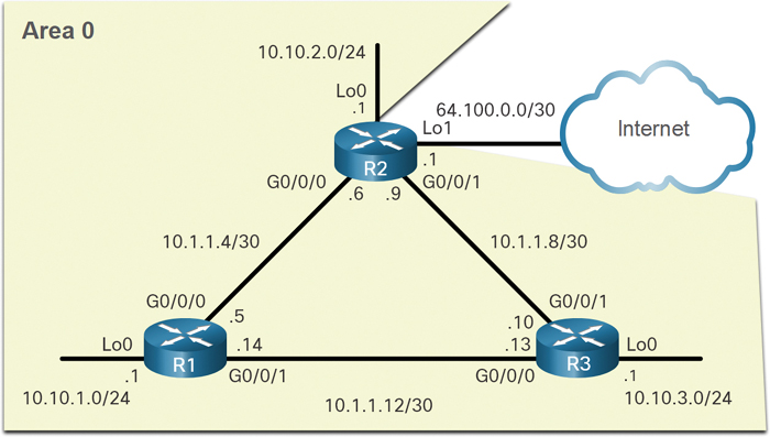
Figure 2-21 OSPF Reference Topology
You can use the show ip ospf neighbor command to verify that a router has formed an adjacency with its neighboring routers. If the router ID of the neighboring router is not displayed, or if it does not show as being in a state of FULL, the two routers have not formed an OSPFv2 adjacency.
If two routers do not establish adjacency, link-state information is not exchanged. Incomplete LSDBs can cause inaccurate SPF trees and routing tables. Routes to destination networks may not exist or may not be the most optimum paths.
Note
A non-DR or non-BDR router (that is, a DROTHER) that has a neighbor relationship with another non-DR or non-BDR router will display a 2-WAY adjacency instead of FULL.
Example 2-38 displays the neighbor table of R1.
Example 2-38 R1’s OSPF Neighbor Table
R1# show ip ospf neighbor
Neighbor ID     Pri   State         Dead Time   Address     Interface
3.3.3.3           0   FULL/  -      00:00:19    10.1.1.13    GigabitEthernet0/0/1
2.2.2.2           0   FULL/  -      00:00:18    10.1.1.6    GigabitEthernet0/0/0
R1#
For each neighbor, the show ip ospf neighbor command displays the following:
Neighbor ID: This is the router ID of the neighboring router.
Pri: This is the OSPFv2 priority of the interface. This value is used in the DR/BDR election.
State: This is the OSPFv2 state of the interface. FULL state means that the router and its neighbor have identical OSPFv2 LSDBs. On multiaccess networks, such as Ethernet, two routers that are adjacent may have their states displayed as 2WAY. The dash indicates that no DR or BDR is required because of the network type.
Dead Time: This is the amount of time remaining that the router waits to receive an OSPFv2 Hello packet from the neighbor before declaring the neighbor down. This value is reset when the interface receives a Hello packet.
Address: This is the IPv4 address of the interface of the neighbor to which this router is directly connected.
Interface: This is the interface on which this router has formed adjacency with the neighbor.
Two routers may not form an OSPFv2 adjacency if the following occurs:
The subnet masks do not match, causing the routers to be on separate networks.
The OSPFv2 Hello or Dead timers do not match.
The OSPFv2 network types do not match.
There is a missing or incorrect OSPFv2 network command.
Verify OSPF Protocol Settings (2.6.2)
Using the show ip protocols command is a quick way to verify vital OSPF configuration information, as shown in Example 2-39.
Example 2-39 Verifying OSPF Protocol Settings
R1# show ip protocols
*** IP Routing is NSF aware ***
(output omitted)
Routing Protocol is "ospf 10"
  Outgoing update filter list for all interfaces is not set
  Incoming update filter list for all interfaces is not set
  Router ID 1.1.1.1
  Number of areas in this router is 1. 1 normal 0 stub 0 nssa
  Maximum path: 4
  Routing for Networks:
  Routing on Interfaces Configured Explicitly (Area 0):
    Loopback0
    GigabitEthernet0/0/1
    GigabitEthernet0/0/0
  Routing Information Sources:
    Gateway         Distance      Last Update
    3.3.3.3              110      00:09:30
    2.2.2.2              110      00:09:58
  Distance: (default is 110)
R1#
The command verifies the OSPFv2 process ID, the router ID, the interfaces explicitly configured to advertise OSPF routes, the neighbors the router is receiving updates from, and the default administrative distance, which is 110 for OSPF.
Verify OSPF Process Information (2.6.3)
The show ip ospf command can also be used to examine the OSPFv2 process ID and router ID, as shown in the Example 2-40.
Example 2-40 Verifying OSPF Process Information
R1# show ip ospf
Routing Process "ospf 10" with ID 1.1.1.1
 Start time: 00:01:47.390, Time elapsed: 00:12:32.320
 Supports only single TOS(TOS0) routes
 Supports opaque LSA
 Supports Link-local Signaling (LLS)
 Supports area transit capability
 Supports NSSA (compatible with RFC 3101)
 Supports Database Exchange Summary List Optimization (RFC 5243)
 Event-log enabled, Maximum number of events: 1000, Mode: cyclic
 Router is not originating router-LSAs with maximum metric
 Initial SPF schedule delay 5000 msecs
 Minimum hold time between two consecutive SPFs 10000 msecs
 Maximum wait time between two consecutive SPFs 10000 msecs
 Incremental-SPF disabled
 Minimum LSA interval 5 secs
 Minimum LSA arrival 1000 msecs
 LSA group pacing timer 240 secs
 Interface flood pacing timer 33 msecs
 Retransmission pacing timer 66 msecs
 EXCHANGE/LOADING adjacency limit: initial 300, process maximum 300
 Number of external LSA 1. Checksum Sum 0x00A1FF
 Number of opaque AS LSA 0. Checksum Sum 0x000000
 Number of DCbitless external and opaque AS LSA 0
 Number of DoNotAge external and opaque AS LSA 0
 Number of areas in this router is 1. 1 normal 0 stub 0 nssa
 Number of areas transit capable is 0
 External flood list length 0
 IETF NSF helper support enabled
 Cisco NSF helper support enabled
 Reference bandwidth unit is 10000 mbps
     Area BACKBONE(0)
        Number of interfaces in this area is 3
     Area has no authentication
     SPF algorithm last executed 00:11:31.231 ago
     SPF algorithm executed 4 times
     Area ranges are
     Number of LSA 3. Checksum Sum 0x00E77E
     Number of opaque link LSA 0. Checksum Sum 0x000000
     Number of DCbitless LSA 0
     Number of indication LSA 0
     Number of DoNotAge LSA 0
     Flood list length 0
R1#
The output verifies the OSPFv2 area information and the last time the SPF algorithm was executed.
Verify OSPF Interface Settings (2.6.4)
The show ip ospf interface command provides a detailed list for every OSPFv2-enabled interface. Specify an interface to display the settings of just that interface. The output in Example 2-41 is for Gigabit Ethernet 0/0/0.
Example 2-41 Verifying OSPF Interface Settings
R1# show ip ospf interface GigabitEthernet 0/0/0
GigabitEthernet0/0/0 is up, line protocol is up
  Internet Address 10.1.1.5/30, Area 0, Attached via Interface Enable
  Process ID 10, Router ID 1.1.1.1, Network Type POINT_TO_POINT, Cost: 10
  Topology-MTID    Cost    Disabled    Shutdown      Topology Name
        0           10        no          no             Base
  Enabled by interface config, including secondary ip addresses
  Transmit Delay is 1 sec, State POINT_TO_POINT
  Timer intervals configured, Hello 5, Dead 20, Wait 20, Retransmit 5
    oob-resync timeout 40
    Hello due in 00:00:01
  Supports Link-local Signaling (LLS)
  Cisco NSF helper support enabled
  IETF NSF helper support enabled
  Index 1/2/2, flood queue length 0
  Next 0x0(0)/0x0(0)/0x0(0)
  Last flood scan length is 1, maximum is 1
  Last flood scan time is 0 msec, maximum is 0 msec
  Neighbor Count is 1, Adjacent neighbor count is 1
    Adjacent with neighbor 2.2.2.2
  Suppress hello for 0 neighbor(s)
R1#
The output in this example verifies the process ID, the local router ID, the type of network, OSPF cost, DR and BDR information on multiaccess links (not shown), and adjacent neighbors.
To get a quick summary of OSPFv2-enabled interfaces, use the show ip ospf interface brief command, as shown in Example 2-42.
Example 2-42 Summary of OSPF Interfaces
R1# show ip ospf interface brief
Interface    PID   Area            IP Address/Mask    Cost  StateNbrs F/C
Lo0          10    0               10.10.1.1/24       10    P2P   0/0
Gi0/0/1      10    0               10.1.1.14/30       30    P2P   1/1
Gi0/0/0      10    0               10.1.1.5/30        10    P2P   1/1
R1#
This command is useful for finding important information including the following:
Interfaces that are participating in OSPF
Networks that are being advertised (IP address/mask)
Cost of each link
Network state
Number of neighbors on each link
Syntax Checker—Verify Single-Area OSPFv2 (2.6.5)
Refer to the online course to complete this activity.
Packet Tracer—Verify Single-Area OSPFv2 (2.6.6)
In this Packet Tracer activity, you will use a variety of commands to verify the single-area OSPFv2 configuration.
Summary (2.7)
The following is a summary of the sections in this chapter.
OSPF Router ID
OSPFv2 is enabled using the router ospf process-id global configuration mode command. The process-id value represents a number between 1 and 65,535 and is selected by the network administrator. An OSPF router ID is a 32-bit value, represented as an IPv4 address. The router ID is used by an OSPF-enabled router to synchronize OSPF databases and participate in the election of the DR and BDR. Cisco routers derive the router ID based on one of three criteria.
The router ID is explicitly configured using the OSPF router-id rid router configuration mode command. The rid value is any 32-bit value expressed as an IPv4 address.
If the router ID is not explicitly configured, the router chooses the highest IPv4 address of any of the configured loopback interfaces.
If no loopback interfaces are configured, then the router chooses the highest active IPv4 address of any of its physical interfaces.
The router ID can be assigned to a loopback interface. The IPv4 address for this type of loopback interface should be configured using a 32-bit subnet mask (255.255.255.255), creating a host route. A 32-bit host route would not get advertised as a route to other OSPF routers. After a router selects a router ID, an active OSPF router does not allow the router ID to be changed until the router is reloaded or the OSPF process is reset. Use the clear ip ospf process privileged EXEC command to reset the adjacencies. You can then verify that R1 is using the new router ID with the show ip protocols command piped to display only the router ID section.
Point-to-Point OSPF Networks
The network command is used to determine which interfaces participate in the routing process for an OSPFv2 area. The basic syntax is network network-address wildcard-mask area area-id. Any interfaces on a router that match the network address in the network command can send and receive OSPF packets. When configuring single-area OSPFv2, the network command must be configured with the same area-id value on all routers. The wildcard mask is typically the inverse of the subnet mask configured on that interface. In a wildcard mask:
Wildcard mask bit 0: Matches the corresponding bit value in the address
Wildcard mask bit 1: Ignores the corresponding bit value in the address
Within routing configuration mode, there are two ways to identify the interfaces that will participate in the OSPFv2 routing process. One way is when the wildcard mask identifies the interface based on the network addresses. Any active interface that is configured with an IPv4 address belonging to that network will participate in the OSPFv2 routing process. The other way is that OSPFv2 can be enabled by specifying the exact interface IPv4 address using a quad-zero wildcard mask. To configure OSPF directly on the interface, use the ip ospf interface configuration mode command. The syntax is ip ospf process-id area area-id. Sending out unneeded messages on a LAN affects the network through inefficient use of bandwidth and resources, and it creates an increased security risk. Use the passive-interface router configuration mode command to stop transmitting routing messages through a router interface but still allow the network to be advertised to other routers. The show ip protocols command is then used to verify that the Loopback 0 interface is listed as passive. The DR/BDR election process is unnecessary as there can only be two routers on the point-to-point network between R1 and R2. Use the ip ospf network point-to-point interface configuration command on all interfaces where you want to disable the DR/BDR election process. Use loopbacks to simulate more networks than the equipment can support. By default, loopback interfaces are advertised as /32 host routes. To simulate a real LAN, the Loopback 0 interface is configured as a point-to-point network.
OSPF Network Types
Routers can be connected to the same switch to form a multiaccess network. Ethernet LANs are the most common example of broadcast multiaccess networks. In broadcast networks, all devices on the network see all broadcast and multicast frames. The DR is responsible for collecting and distributing LSAs. The DR uses the multicast IPv4 address 224.0.0.5, which is meant for all OSPF routers. If the DR stops producing Hello packets, the BDR promotes itself and assumes the role of DR. Every other router becomes a DROTHER. DROTHERs use the multiaccess address 224.0.0.6 (all designated routers) to send OSPF packets to the DR and BDR. Only the DR and BDR listen for 224.0.0.6. To verify the roles of the OSPFv2 router, use the show ip ospf interface command. To verify the OSPFv2 adjacencies, use the show ip ospf neighbor command. The state of neighbors in multiaccess networks can be:
FULL/DROTHER: This is a DR or BDR router that is fully adjacent with a non-DR or BDR router.
FULL/DR: The router is fully adjacent with the indicated DR neighbor.
FULL/BDR: The router is fully adjacent with the indicated BDR neighbor.
2-WAY/DROTHER: The non-DR or BDR router has a neighbor relationship with another non-DR or BDR router.
The OSPF DR and BDR election decision is based on the particular criteria. The routers in the network elect the router with the highest interface priority as the DR. The router with the second-highest interface priority is elected as the BDR. The priority can be configured to be any number between 0 and 255. If the interface priority value is set to 0, that interface cannot be elected as DR or as BDR. The default priority of multiaccess broadcast interfaces is 1. Therefore, unless otherwise configured, all routers have an equal priority value and must rely on another tie-breaking method during the DR/BDR election.
If the interface priorities are equal, then the router with the highest router ID is elected the DR. The router with the second-highest router ID is the BDR.
OSPF DR and BDR elections are not preemptive. If the DR fails, the BDR is automatically promoted to DR. This is the case even if another DROTHER with a higher priority or router ID is added to the network after the initial DR/BDR election. However, after a BDR is promoted to DR, a new BDR election occurs, and the DROTHER with the highest priority or router ID is elected as the new BDR. To set the priority of an interface, use the ip ospf priority value interface configuration command, where value is 0 to 255. If value is 0, the router will not become a DR or BDR. If value is 1 to 255, then the router with the higher priority value will more likely become the DR or BDR on the interface.
Modify Single-Area OSPFv2
OSPF uses cost as a metric. A lower cost indicates a better path than a higher cost. The Cisco cost of an interface is inversely proportional to the bandwidth of the interface. Therefore, a higher bandwidth indicates a lower cost. The formula used to calculate the OSPF cost is Cost = reference bandwidth / interface bandwidth. Because the OSPF cost value must be an integer, FastEthernet, Gigabit Ethernet, and 10 Gigabit Ethernet interfaces share the same cost. To correct this situation, you can adjust the reference bandwidth with the auto-cost reference-bandwidth router configuration command on each OSPF router or manually set the OSPF cost value with the ip ospf cost interface configuration command. To adjust the reference bandwidth, use the auto-cost reference-bandwidth Mbps router configuration command. The cost of an OSPF route is the accumulated value from one router to the destination network. OSPF cost values can be manipulated to influence the route chosen by OSPF. To change the cost value report by the local OSPF router to other OSPF routers, use the ip ospf cost value interface configuration command. If the Dead interval expires before the routers receive a Hello packet, OSPF removes that neighbor from its link-state database (LSDB). The router floods the LSDB with information about the down neighbor out all OSPF-enabled interfaces. Cisco uses a default of four times the Hello interval, or 40 seconds on multiaccess and point-to-point networks. To verify the OSPFv2 interface intervals, use the show ip ospf interface command. OSPFv2 Hello and Dead intervals can be modified manually using the following interface configuration mode commands: ip ospf hello-interval seconds and ip ospf dead-interval seconds.
Default Route Propagation
In OSPF terminology, the router located between an OSPF routing domain and a non-OSPF network is called the ASBR. To propagate a default route, the ASBR must be configured with a default static route using the ip route 0.0.0.0 0.0.0.0 [next-hop-address | exit-intf] global configuration command and the default-information originate router configuration command. This instructs the ASBR to be the source of the default route information and propagate the default static route in OSPF updates. Verify the default route settings on the ASBR by using the show ip route command.
Verify Single-Area OSPFv2
The following two commands are used to verify routing:
show ip interface brief: Used to verify that the desired interfaces are active with correct IP addressing.
show ip route: Used to verify that the routing table contains all the expected routes.
Additional commands for determining that OSPF is operating as expected include show ip ospf neighbor, show ip protocols, show ip ospf, and show ip ospf interface.
Use the show ip ospf neighbor command to verify that the router has formed an adjacency with its neighboring routers. For each neighbor, this command displays:
Neighbor ID: The router ID of the neighboring router.
Pri: The OSPFv2 priority of the interface. This value is used in the DR and BDR election.
State: The OSPFv2 state of the interface. FULL state means that the router and its neighbor have identical OSPFv2 LSDBs. On multiaccess networks, such as Ethernet, two routers that are adjacent may have their states displayed as 2WAY. The dash indicates that no DR or BDR is required because of the network type.
Dead Time: The amount of time remaining that the router waits to receive an OSPFv2 Hello packet from the neighbor before declaring the neighbor down. This value is reset when the interface receives a Hello packet.
Address: The IPv4 address of the neighbor’s interface to which this router is directly connected.
Interface: The interface on which this router has formed adjacency with the neighbor.
Using the show ip protocols command is a quick way to verify vital OSPF configuration information such as the OSPFv2 process ID, the router ID, the interfaces explicitly configured to advertise OSPF routes, the neighbors the router is receiving updates from, and the default administrative distance, which is 110 for OSPF. Use the show ip ospf command to examine the OSPFv2 process ID and router ID. This command displays the OSPFv2 area information and the last time the SPF algorithm was executed. The show ip ospf interface command provides a detailed list for every OSPFv2-enabled interface. Specify an interface for just one interface to display the process ID, the local router ID, the type of network, OSPF cost, DR and BDR information on multiaccess links, and adjacent neighbors.
Packet Tracer—Single-Area OSPFv2 Configuration (2.7.1)
You are helping a network engineer test an OSPF setup by building the network in the lab where you work. You have interconnected the devices and configured the interfaces and have connectivity within the local LANs. Your job is to complete the OSPF configuration according to the requirements left by the engineer.
In this Packet Tracer activity, use the information provided and the list of requirements to configure the test network. When the task has been successfully completed, all hosts should be able to ping the internet server.
Lab—Single-Area OSPFv2 Configuration (2.7.2)
![]()
In this lab, you will complete the following objectives:
Part 1: Build the network and configure basic device settings
Part 2: Configure and verify single-area OSPFv2 for basic operation
Part 3: Optimize and verify the single-area OSPFv2 configuration
Practice
The following activities provide practice with the topics introduced in this chapter. The labs are available in the companion Enterprise Networking, Security, and Automation Labs & Study Guide (CCNAv7)(ISBN 9780136634690). The Packet Tracer activity instructions are also in the Labs & Study Guide. The PKA files are found in the online course.
Lab
![]()
Lab 2.7.2: Single-Area OSPFv2 Configuration
Packet Tracer Activities
Packet Tracer 2.2.13: Point-to-Point Single-Area OSPFv2 Configuration
Packet Tracer 2.3.11: Determine the DR and BDR
Packet Tracer 2.4.11: Modify Single-Area OSPFv2
Packet Tracer 2.5.3: Propagate a Default Route in OSPFv2
Packet Tracer 2.6.6: Verify Single-Area OSPFv2
Packet Tracer 2.7.1: Single-Area OSPFv2 Configuration
Check Your Understanding
Complete all the review questions listed here to test your understanding of the topics and concepts in this chapter. The appendix “Answers to the ‘Check Your Understanding’ Questions” lists the answers.
1. A router is participating in an OSPFv2 domain. What will always happen if the Dead interval expires before the router receives a Hello packet from an adjacent OSPF router?
A new Dead interval timer of four times the Hello interval will start.
OSPF will remove that neighbor from the router’s link-state database.
OSPF will run a new DR/BDR election.
SPF will run and determine which neighbor router is down.
2. What is the first criterion used by OSPF routers to elect a DR?
Highest priority
Highest IP address
Highest router ID
Highest MAC address
3. Which wildcard mask would be used to advertise the 192.168.5.96/27 network as part of an OSPF configuration?
0.0.0.31
0.0.0.32
255.255.255.223
255.255.255.224
4. Which command would be used to determine if an OSPF routing protocol- initiated relationship had been made with an adjacent router?
ping
show ip interface brief
show ip ospf neighbor
show ip protocols
5. Which command is used to verify the OSPFv2 router ID, the interfaces explicitly configured to advertise OSPF routes, the passive interfaces, the neighbors the router is receiving updates from, and the default administrative distance, which is 110 for OSPF?
show ip interface brief
show ip ospf interface
show ip protocols
show ip route ospf
6. Two OSPFv2 routers are interconnected using a point-to-point WAN link.Which command could be used to verify the configured Hello and Dead timer intervals?
show ip ospf neighbor
show ip ospf interface fastethernet 0/1
show ip ospf interface serial 0/0/0
show ipv6 ospf interface serial 0/0/0
7. You are troubleshooting convergence and adjacency issues in an OSPFv2 network and have noticed that network route entries are missing from the routing table. Which commands provide additional information about the state of router adjacencies, timer intervals, and the area ID? (Choose two.)
show ip ospf interface
show ip ospf neighbor
show ip protocols
show ip route ospf
show running-configuration
8. A network engineer has manually configured the Hello interval to 15 seconds on an interface of a router that is running OSPFv2. By default, how will the Dead interval on the interface be affected?
The Dead interval will not change from the default value.
The Dead interval will now be 15 seconds.
The Dead interval will now be 30 seconds.
The Dead interval will now be 60 seconds.
9. To establish a neighbor adjacency, two OSPF routers exchange Hello packets. Which values in the Hello packets must match on the two routers? (Choose two.)
Dead interval
Hello interval
List of neighbors
Router ID
Router priority
10. What is the default router priority value for all Cisco OSPF routers?
0
1
10
255
11. What indicates to a link-state router that a neighbor is unreachable?
The router no longer receives Hello packets.
The router no longer receives routing updates.
The router receives an LSP with previously learned information.
The router receives an update with a hop count of 16.
12. Which of the following will OSPF use when it chooses its router ID?
A loopback interface that is configured with the highest IP address on the router
The highest active interface IP address that is configured on the router
The lowest active interface IP address that is configured on the router
The highest active interface that participates in the routing process because of a specifically configured network statement
13. An OSPF router has three directly connected networks; 10.1.0.0/16, 10.1.1.0/16, and 10.1.2.0/16. Which OSPF network command would advertise only the 10.1.1.0 network to neighbors?
router(config-router)# network 10.1.0.0 0.0.15.255 area 0
router(config-router)# network 10.1.1.0 0.0.0.0 area 0
router(config-router)# network 10.1.1.0 0.0.0.255 area 0
router(config-router)# network 10.1.1.0 0.0.255.255 area 0
14. By default, what is the OSPF cost for a link with Gigabit Ethernet interfaces?
1
100
10000
100000000
15. An administrator is configuring single-area OSPF on a router. One of the networks that must be advertised is 64.100.1.64 255.255.255.192. Which OSPF network statement should be configured?
network 64.100.1.64 0.0.0.15 area 0
network 64.100.1.64 0.0.0.31 area 0
network 64.100.1.64 0.0.0.63 area 0
network 64.100.1.64 0.0.0.127 area 0
16. Which of these factors will prevent two routers from forming an OSPFv2 adjacency? (Choose two.)
Mismatched Cisco IOS versions
Mismatched Ethernet interfaces (for example, Fa0/0 to G0/0)
Mismatched OSPF Hello or Dead timers
Mismatched subnet masks on the link interfaces
Use of private IP addresses on the link interfaces