techniques and stages of creating 3D computer animation
by Marcia Kuperberg
by Marcia Kuperberg
Techniques and stages of creating 3D computer animation
INTRODUCTION
This chapter takes you stage by stage through practical 3D polygonal model making and camera animation. Included are tips on lighting your scene.
When you have finished reading this chapter and trying out the techniques demonstrated, you will have a basic understanding of:
• How to set about the task of creating a 3D room – working from a brief.
• How to think about everyday objects around you and translate them into 3D models using some basic methods of polygonal construction.
• How to make your models look realistic and interesting through the application of textures and materials.
• Types of lights commonly used in 3D computer animation, and how to use them effectively to light your scene.
• Using virtual cameras to create views from various angles and to move around your scene.
If you’ve read Chapter 1, you’ll have a broad understanding of how – over the centuries – artists, photographers and inventors brought us to where we are today, sitting at our desks, contemplating creating animation with the aid of computer technology.
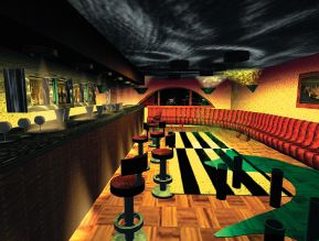
Fig. 3.1 First year students on a BA (Hons) Media Production course at West Herts College, Watford (near London) were given a brief to create a 3D room using three basic methods of polygonal model making. Using 3DS MAX release 3, they completed the exercise in about 30 hours, having had no prior experience of using 3D software. This is a bar scene created by Daniel Acharya and Jeetinder Mattu.
The use of strong colours, contrasting tones and volumetric lighting help create the atmosphere.
© West Herts College 2001.
No matter how clever the technology is, the fact remains that you, the animator, are the creative force behind whatever your audience sees on screen. If you want that to be entertaining and worth viewing, you’ll try to apply the animation principles that were outlined in the chapter.
Hopefully, you’ve also read part or all of Chapter 2 to help you bust through the techno speak – and now you’re ready to have a go at tackling some 3D work.
BUT, before you grab your mouse and hunch forward in your swivel chair, here are some tips to help you tackle the job:
1. Follow the brief.
2. Schedule your work to deliver on time.
3. Do the necessary background research.
4. Check the proposed action and framing from your storyboard before creating the model.
5. Think about the quickest, most efficient way to make your models.
6. Pay great attention to materials.
7. Pay equal attention to lighting your scene.
8. Use your virtual camera effectively but unobtrusively.
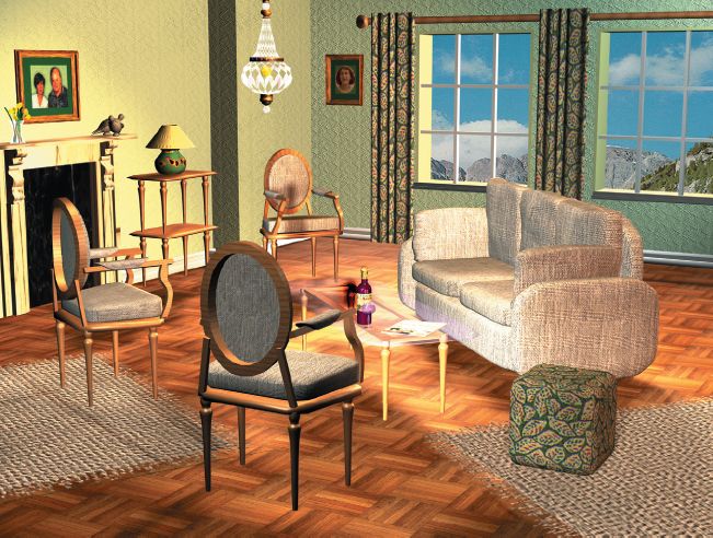
Fig. 3.2 I created this traditional French-style living room using simple polygonal modeling techniques available in most 3D software. 3DS Max 3 was used here.
The process of making each item is explained in this chapter.
© Marcia Kuperberg 2001.
Let’s look briefly at each of these points and then we’ll examine a room model to see their application in practice.
FOLLOWING THE BRIEF
You are normally given a brief by a client. This should always be written not verbal, as you will constantly need to refer to it. If you are given a verbal brief, you should confirm the requirements in writing to avoid any misunderstandings. If any parts of the brief are unclear, then you should go back to the client (or tutor) for clarification. Any changes to the original brief should, again, be confirmed in writing.
If you are working for a client, and the client changes the brief, i.e. has a change of mind, part way through the job, the changes may well have an impact on your ability to deliver on time. It’s as well to be ‘up front’ about this, as the client may have no idea of how much time can be involved in what may seem a minor change to the original requirement. It’s not smart to agree to make the changes, only to discover that a) it will double the cost and b) it can no longer be delivered on time. Always ensure that the proposed production storyboard is approved by the client before beginning a job.
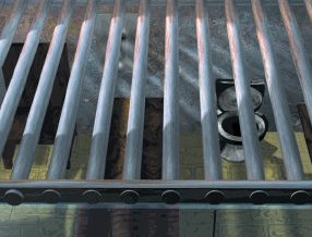
Fig. 3.3 Hannibal Lecter style prison cell seen from above, by Stuart Birchall and Alex Dunn of West Herts College. Cross pattern of bars and shadows makes this simple model interesting.
© West Herts College 2001.
SCHEDULING YOUR WORK TO DELIVER ON TIME
This is always difficult, because if you’re a beginner, you don’t know how long things will take. Before long, you’ll have an idea however, and you’ll need to scale your ambitions in line with your likely productivity if you are to meet a given deadline. Make sure you plan in sufficient time for research, time for meetings if you’re working in a team, rethinking/ doing after critical feedback, time for experimentation, time for rendering, and contingency time if anything goes wrong.
DOING YOUR RESEARCH
Suppose you were following the same ‘construct a room’ brief as given to the BA Media students here, you would firstly need to decide what type of room you planned to create. Students chose a wide variety of rooms including those shown here (figs 3.1, 3.3 and 3.4).
Let’s say you have decided upon a living room. You need to ask further questions in order to progress with the necessary picture research.
Some of these questions might be:
• What type and period is the house containing this room?
• Who will be living in the house? This is when you think about the type of people who would be likely to choose a particular style of decor for their living room – their age and rough income bracket, the type of work they would do, their family situation etc. This would have considerable bearing on the look of the room you aim to create and the objects likely to be in it.
Having made that decision, you should jot down ideas for the design, possible colour scheme, items in the room and then gather as much reference material as you can. This is likely to cover a number of areas:
• colour ideas for different colour schemes;
• textures and patterns and images for items within the room: think of curtains, carpets, cushions, rugs, floors, furniture, light fitments and similar fixtures, patterns on ornaments and crockery, photographs/paintings on the walls;
• room settings of the type of room you plan to create;
• pictures of individual items you plan to include in your room.
Remember, it is unlikely that you will attempt to duplicate any of these things accurately; they act as a springboard for your own ideas and also provide valuable modeling reference as to the shape and makeup of general items. You will need to adjust your ideas to your modeling capabilities. At an introductory level of expertise, you are restricting yourself to modeling that can be accomplished using some of the most basic techniques – even though you want the finished effect to look totally professional.
• Lighting and shadow effects. Here you should consider the time of day of your sequence, whether there are lights to be shown as switched on (aside from lights you will use to light the objects and the scene), and the atmosphere you want to create.
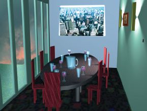
Fig. 3.4 This boardroom by Cerys Hill and Joanna Goodman gains its attraction by the use of a subtle colour scheme and the pattern made by the wall lights.
© West Herts College 2001.
CHECKING THE PROPOSED ACTION FROM YOUR STORYBOARD BEFORE CREATING THE MODEL
The original purpose of the brief in this instance was to familiarize students in basic techniques of 3D polygonal modeling so there was little animation involved.
If you were to go to the trouble of creating the entire room model and only then think about the action that is meant to take place within it, some of your modeling efforts could be wasted. There may be an item within your environment that is only ever seen in the distance and you should be aware of that fact before you create it in order to minimize the modeling effort spent. You don’t want to spend ages working on model details that will never be seen. This is a general principle that you should apply to all your models, regardless of what it is you’re creating, or how experienced you are.
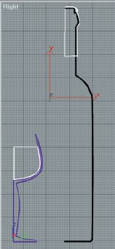
Fig. 3.5 The profile of the bottle and the wine glass should be created in the front or side viewport and lathed (another term is ‘swept’) 360 degrees around the Y-axis, aligning at the minimum (leftmost) point.
THINKING ABOUT THE MOST EFFICIENT WAY TO MAKE YOUR MODELS
It is surprising how effective your models can appear, by using the simplest of modeling techniques – providing you make good use of materials, textures and lighting. At this introductory level, you are going to create your room model using the following basic techniques:
• Utilizing ready-made ‘primitives’. Primitives are ready-made, standard 3D geometric objects, e.g. spheres, boxes, cylinders, pyramids etc. (fig. 3.7), and then modifying them to suit your purpose, e.g. squashing, tapering, curving or bending, or pulling out vertices or faces – before finally grouping them to form your object, e.g. a sofa (figs 3.8 and 3.9).
• Creating a 2D shape and extruding it along a straight path to give it depth.
• Lathing (or ‘sweeping’) a profile of a 2D shape around a circular path to create a symmetrical 3D object, e.g. a wine glass, a bottle, a cup or a saucer (figs 3.5 and 3.6).
By now you will have your pictorial and other reference in and it is time to begin to think about creating your models. You may not consider yourself to be an artist, but you should still sketch out your basic ideas for your room and indicate in note form any particular pictorial or other references.
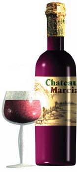
Fig. 3.6 After lathing and rendering.
Images on this double page spread © Marcia Kuperberg 2001.
Polygons, patches, NURBS, metaballs, polygons
If you’ve read Chapter 2, you’ll know that there are a number of different sorts of modeling available to you – you can choose any one method, or a combination of them all depending upon your software, the requirements of your scene and your own capabilities.
If you’re just setting out in the world of 3D modeling, working with polygons is the best place to start. You’ll probably find it easier and you can create surprisingly sophisticated looking scenes – particularly if the scenes are composed of non-organic objects like furniture. You’ll mainly use boxes and other primitives, which you tweak, manipulate and modify. The great thing about working with polygons and many of today’s object oriented parametric software packages is that if you change your mind part way through, you don’t have to start again from scratch. This type of software stores commands in the construction process. This means that usually you can go back to an earlier command and change it, without having to rebuild other aspects of your model.
CONSTRUCTING THE BASIC ROOM
• Only build what you need to. Just as in a film set, you only need build the parts that will be seen by the camera – in this case, two walls, the floor and the ceiling if the camera tilts up.
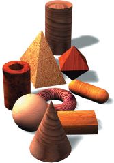
Fig. 3.7 Primitive geometric objects: your building blocks for some types of modeling.
• Examine everyday objects around you. In your mind’s eye, try to simplify their basic construction into primitives that can be modified as required, then grouped to form objects.
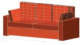
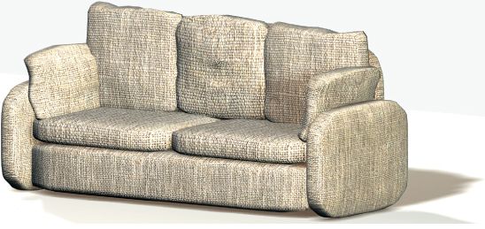
Fig. 3.8 The sofa has been created from manipulated boxes.
• Use the correct scale. It’s a good idea to create your room and the objects within it in the correct scale right from the start. This does not mean that you should be an architect, a builder or have a product engineering qualification! It just means that you should firstly consider the likely general dimensions of the walls, windows and floors. A good idea is to measure items around you if unsure. You should then create the furniture and other items in scale to those larger parts of the scene as well as to each other. It doesn’t matter whether you’re working to a metric or imperial scale, as long as you roughly match the scale from graph paper where you choose to draw your sketches to the computer where you do your modeling.
Before starting your project, set up your software ‘Preferences’ to the scale of your choice (fig. 3.10) and have a supply of matching graph paper to hand. Again, I don’t suggest that you sketch every little detail of each and every item on paper before creating it – just the general size, scale and shape of the various objects.
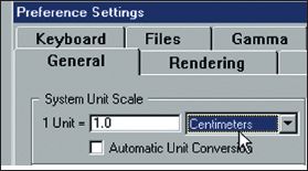
Fig. 3.10 3DS Max Preferences, in this case set to cm but you can decide on any unit of measurement.
This may first seem to be a waste of time. After all, you can start creating straight away – directly into the computer – item by item, at different times on different computers if on a network, and then merge each of these items into the final scene, scaling each item up or down to fit in with the size of other items within the scene.
However, if you adopt this approach, you may strike difficulties further down the line. Suppose you are creating a coffee cup and saucer that will be on a coffee table. If you are sharing the modeling tasks of your scene with others, it would be easy to spend quite some time creating a beautifully decorated fluted edge to your cup. You would see all your careful detail in its full glory. However, when the entire animation is finished, and you realize that your beautiful coffee cup is only seen in a shadowed long shot, you might well feel that all your effort was wasted.
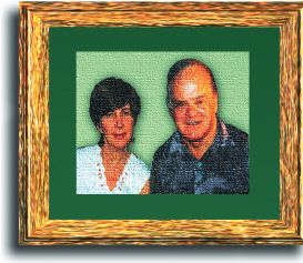
Fig. 3.11 The family images in the centre of the frame in this and fig. 3.12 are scanned photos manipulated in Photoshop to add the textured ‘canvas’ look and the cutout oval in fig. 3.12.
The other benefit of working to the correct scale from the beginning is that others can work on individual items (having first checked the storyboard) and these can then be merged as they are, into the final scene with no further scaling. If modeling tasks are being shared, nominate someone to keep the master room file, so when individual items are created, only one person sends the update to all. Everyone should have copies of concept drawings and model sheets done to the scale used in the computers as well as storyboards.
The floor and the left wall. These are primitives: boxes, snapped into place at right angles to each other.
The wall with the windows. The back wall began life as three rectangles (shapes) – first the large one (the wall), and then the two inner ones (one for each window). All – as one complete set of shapes – were then extruded to the thickness of an outer wall. In order to be able to extrude all the rectangles together, as a single shape (so that the inner rectangles became holes for the windows), it was necessary to ‘tell’ the software not to ‘start a new shape’ when creating each of the secondary rectangles. An alternative is to edit the spline and attach all shapes to make one overall shape before extruding.
The left windowpanes were made by creating four intersecting long thin rectangles inside the window hole – two vertically and two horizontally (snapping to the grid). These were then cloned to make the right windowpanes. Then all were extruded – this time to a much lesser depth – and moved nearer the front of the window holes.
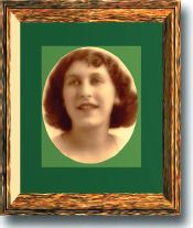
The pictures on the walls. The pictures inside the frames are 2D planes (figs 3.11 and 3.12). These are, in effect, renderable shapes as thin as paper. The pictures are scanned images of family photos that were manipulated in Photoshop to add – in one case – a canvas-like texture and in the other a slightly textured background behind a cutout oval. These images were then mapped as materials (planar projections) onto the planes.
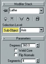
Fig. 3.13 Max screen grab showing access to the Sub-Object, Axis and only four segments for rotation.
The picture frames were created as 2D shape profiles (fig. 3.14) that were lathed around 360 degrees. Usually, when lathing a 2D profile, say, for creating an object such as the lamp base or a bottle, it will be lathed around the minimum axis so that there is no hole in the middle of the final object. Also, in order for the end object to appear rounded, it will have a minimum of ten segments when rotated around the axis.
In the case of the picture frames, there are only four segments – one for each side – and the axis of rotation (a ‘sub-object’ of the lathe modification) has been moved in the X direction to give a hole in the frame’s centre (fig. 3.13).
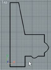
Fig. 3.14 Picture frame profile (stage prior to ‘lathing’ ).
Images © Marcia Kuperberg 2001.
The skirting board. This is a thin side section which has been extruded to the width of one wall, then copied and placed into position for the other walls. It was also used for each of the windowsills – manipulating the original shape slightly, again copied but made shorter to fit across the bottom of the windowpanes (a builder might not approve!). Firstly the side section was made as a linear (straight lined) shape, snapped to the grid on one side, the side to be placed directly against the wall. Then the sub-object (vertices) was turned on and a vertex was selected, made into a bezier curve and manipulated via its handles into the curve required.
The curtains. There are a number of ways you can make these. A simple way is to make the curved edges in the top viewport and extrude them to the length desired (fig. 3.15).
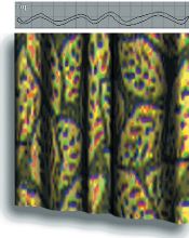
Fig. 3.15 Top: curves created in the top viewport and then extruded to make the curtains.
The sofa is just a group of eleven primitive boxes manipulated in various ways, including mesh ‘smoothing’ (fig. 3.17). It is advisable to map textures (this topic is covered later in this chapter) at this early stage rather than after further modification to avoid texture distortion.
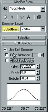
Fig. 3.16 In 3DS Max, soft selection of vertices allows you to pull out vertices in a graduated way.
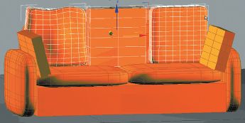
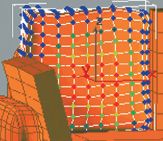
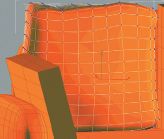
Smoothing the mesh increases the number of polygons and gives rounded corners to the sofa cushions shown here in figs 3.18 and 3.19. In fig. 3.18 the colour of the vertices gives an indication of the degree of fall off when pulled out as per settings in fig. 3.16 using 3DS Max release 3.
Your software may give you a variety of mesh smoothing techniques. Experiment to choose the method that gives you the end shape you prefer whilst trying to keep your polygon count as low as possible. The more you smooth, the ‘tighter’ but smoother the rounded parts will appear and the greater number of polygons you make (fig. 3.18), but – although you want to make the perfect object, bear in mind:
• the distance of your smoothed object from camera (will anyone actually notice those beautifully smoothed edges?)
• if you have too many unnecessary additional polygons in your model, your scene will take much longer to render – maybe not so noticeable when you just do a trial single image, but very noticeable when you need to render thousands of images for an extended animation. Keeping a low polygon count is even more crucial if creating models for use in computer games. For more on this, read Chapter 5.
The sofa’s squashy back and side cushions. First create the box primitives – allow yourself a few more segments as you’ll need to pull out a few vertices. Make one box and make copies for the other cushions from this. Instances or copies? Your software will probably allow you to choose whether to make ‘instances’ from your original or independent copies. Making an ‘instance’ means that when you change the original, all the instances automatically change too. This can be useful and a great timesaver – say you’re creating a group of same-design chairs (as indeed you may well do if you decide to create a room like this). You might decide to change the basic shape of one chair leg and hey presto – all the other (instanced) legs change, too. Your sofa’s back and side cushions, however, require slight variations to each, so in this case, you make copies from your original cushion, not instances. Smooth your mesh (fig. 3.17) to give rounded edges to otherwise box-like objects.
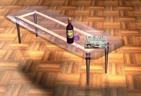
The glass topped coffee table The tabletop is a primitive box with its mesh smoothed to round off the corners and edges, giving it a slightly bevelled effect. It has a glass material applied. The table legs are copies of the chair legs with the same rosewood material. One chair leg was copied and instances made of the others. The legs were positioned in the top and front viewports in wire frame.
The magazine on top of the table is a thin box primitive with a scanned image of a magazine cover. Yo u can’t see it too clearly here but the 3D scene constructed in this chapter is based on the scene depicted on the cover. You can see this more clearly in fig. 3.47.
The bottle and glass on the table are made from lathed shapes (figs 3.5 and 3.6).
Soft selection. Select the vertex or vertices you want to pull out to further soften the basic rounded box shape. If your software has a ‘soft selection’ facility, this will be of great help. Soft selection allows you to select one or more vertices and the vertices in the surrounding area that you designate as your ‘fall off’ will also be pulled out – gradually falling away to the surrounding surface (fig. 3.18). In Max, you can set parameters to change the shape of the pulled out ‘bubble’ as well as the steepness of the surrounding fall off (fig. 3.16).
The footstool next to the sofa. This is a box with its mesh smoothed to round off the edges. The corner shape will change according to its number of segments (fig. 3.21).
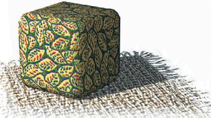
Fig. 3.21 Footstool
Images © Marcia Kuperberg 2001.
The antique chairs
The chair backrest. Firstly, create an ellipse shape and turn off any ‘start new shape’ option so that when you create a second ellipse inside the first one (fig. 3.22), they can be extruded as a single shape. Your software will probably allow you to do this by an ‘outline’ function or you can simply create a smaller oval inside the first one. Extrude the combined shapes having edited the spline to attach them. Bend the oval frame as shown in fig. 3.23.
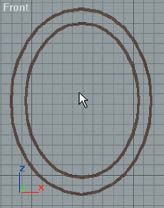
Fig. 3.22 Oval shapes are extruded to make the backrest frame.
![]()
Fig. 3.23 Side view of oval backrest bent 30 degrees on the X-axis.
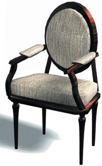
Fig. 3.24 Antique chair.
The backrest cushion. Create another ellipse shape from the centre of your chair back frame, sized a little larger than the inner ellipse. Extrude the shape. Soft selection of vertices has been used in the same way as on the cushion of the sofa (figs 3.25 and 3.26).
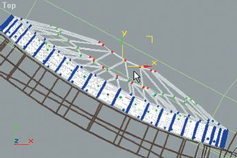
Fig. 3.25 Top view of the chair backrest showing the vertices pulled out using soft selection.
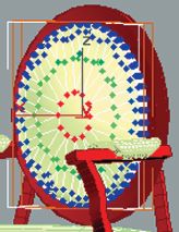
Fig. 3.26 Soft selection on back.
The chair seat cushion. As with the seat cushions of the sofa, this is a box primitive with the mesh smoothed to curve the edges. Using the top viewport, taper the cushion to make the back shorter than the front and after making the base underneath, check that the bottom of the cushion is firmly placed on the base.
The base under the seat cushion is a copy of the cushion (not an instance, as its size will be changed and the thickness lessened and scaled to be ever so slightly larger than the cushion). It will also end up with a wooden material to match the back frame, armrests and chair legs.
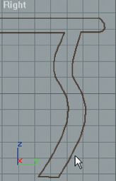
Fig. 3.27 Chair armrest profile created in side view.
The armrests. Start off with a side profile shape using straight lines snapped to the grid using the rest of the chair as a guide for size. Turn off the snap-to-grid function and change some of the vertices into bezier ones with handles that you can manipulate to create the curves in your shape (fig. 3.27). Extrude the shape to the desired thickness. Using the top and front viewports, rotate the armrest so that one side touches the oval backrest and the other is at the front corner of the seat. Mirror and copy this (as an ‘instance’) to make the other armrest.
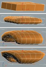
Fig. 3.28 Stages of making the armrest pads: 1) a box, 2) the box smoothed to round off the corners, 3) the box bent and 4) the box tapered.
The little padded parts on top of the armrests began as boxes originally with three segments, later smoothed (creating the box with extra segments allows the box to be bent later), then bent 200 degrees on the X-axis in the front viewport, tapered and then rotated and placed into position on top of the armrests (figs 3.24 and 3.28).
The chair legs. Here the profile was created and then lathed (another term is ‘swept’) around 360 degrees, aligning the shape on the minimum point – the centre of the 360-degree circle (fig. 3.29). Having made one chair leg, make instances of the other three and position them at each corner of the chair, ensuring their alignment with the bottom edges of the armrests.
![]()
Fig. 3.29 Chair leg profile.
Images © Marcia Kuperberg 2001.
Once you’ve completed one chair, and laid your chosen materials on it, you can group all the components of the chair and make instances of it for the other chairs. The chair here has a rosewood material for the wooden parts and the same bumpy beige fabric used for the sofa was used for the other parts (fig. 3.24). In the full room scene (fig. 3.2) the chairs have a lighter beechwood material.
The fireplace. Like much of the room, this consists of a number of boxes or extruded shapes. The carved, curly pieces beneath the mantelpiece were begun as a single curved shape created in the side viewport, which was then extruded and copied (as an instance) to the other side. The stepped panelling on the sides was done similarly – original shape created in the top viewport, extruded to the floor – then mirrored and copied (as an instance) to the other side.
The vase and the flowers. The vase is a primitive tube, tapered, curved and given a transparent glass material. The flowers are instances of an extruded shape, rotated and placed onto the bent stalks (long boxes with sufficient segments to allow them to be bent).
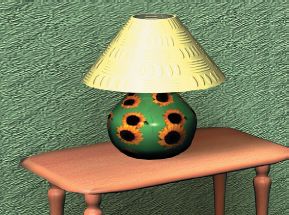
Fig 3.31 Complete lamp on beechwood coffee table.
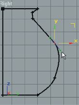
As the lamp profile will be lathed around 360 degrees, it is important that the left-hand line is straight (it will be the centre) and that the base is also straight. Weld the vertices created by lathing to get rid of any unnecessary ones in the centre of your object. When you begin to create your shape, use the ‘snap-to-grid’ function to get the basic shape quickly. Then go to the ‘sub-object’ level to access the vertices, ‘refine’ if you want to add some more, and make some of them into bezier curves to manipulate the shape.
The lampshade is a tapered tube.
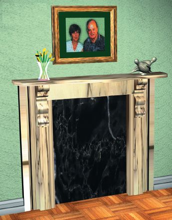
Fig. 3.32
The ornamental doves. The dove is made up from a number of objects: the pedestal base, the body and head, wings, eyes and beak.
The pedestal base is just a primitive box with few segments, smoothed and tapered, the eyes are two primitive hemispheres and the beak a cone.
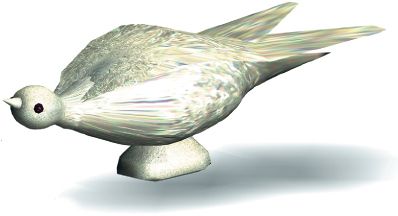
The dove head and body is a lathed shape that was then further modified by using a lattice, a very useful modeling device. It can be applied to the whole object or just a part of it by first selecting a group of vertices, then selecting the lattice option (which then automatically surrounds the selected vertices: fig. 3.35). You then go to the lattice’s sub-object level to select control points which you can move, scale or rotate to affect the shape of the enclosed object. Using the lattice’s control points, the head was made smaller and rotated to tilt upwards.

Fig. 3.34 Profile of bird (side view).
The wing was originally created in the top view as a primitive plane with six length and eight width segments. An edit mesh modifier was applied in order to get to the sub-object vertex level where the vertices were scaled and moved to create a basic boat-like shape. To make the wing curve around the bird body, the plane was bent in the front viewport by first moving the (sub-object) centre along the X-axis (inset fig. 3.36) and then bending 45 degrees on X using Max’s sub-object ‘gizmo’. It was bent again, this time in the right view, 45 degrees on the Y-axis, with a minus 45 degree direction. Then various lattice modifiers were applied to give the final wing shape. The wing was then rotated into its position on the bird body and then mirror copied as an instance to form the second wing (fig. 3.36).

Fig. 3.35 Use of lattice to angle and reshape a selected area.
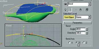
Fig. 3.36 Curving the wings around the bird’s body. After one wing is curved and placed on top and further manipulated as required, a second wing is made as a mirrored instance and placed into position.
Images © Marcia Kuperberg 2001.
The chandelier and the metallic chain
The chandelier is made up of a number of parts as shown in fig. 3.39. The beaded ‘cut glass’ effect is achieved by creating faceted rather than smoothed cylinders and spheres, with the cylinders manipulated as shown in fig. 3.40. Parts 4 and 6 of the chandelier have been made with ‘circular arrays’.
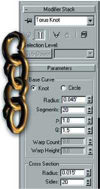
Fig. 3.37 The ‘torus knot’ is an extended primitive in Max that can be manipulated as shown to form links. For non-Max users, make a torus and in vertex mode, select the vertices of the bottom half of the torus and drag downwards. The links were rotated and moved into position and instanced to form the chain. A yellow ochre material was applied with shine added.
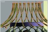
Fig. 3.38 Circular array, part 4 of the chandelier after bending.

1. small cylinder
2. small sphere with eight segments
3. lathed shape
4. circular array of cylinders curving inwards (fig. 3.38)
5. brass ring
6. circular array of cylinders in a bulb shape
7. ring
8. lathed shape
9. faceted sphere
A lightbulb to be placed inside is just a smoothed sphere (also see fig. 3.68).
![]()
Fig. 3.40 Cylinder, manipulated at sub-object vertex level.
To create the top circular array (no. 4, Fig. 3.39), first create a single faceted cylinder (or an ordinary cylinder on which you remove the smoothing groups). The circular array will require a common centre for all the cylinders arrayed around it. This can be a moved pivot point of the object itself, the world centre or the centre of the grid (in Max you can select ‘Use transform centre’ so that the centre of the grid becomes the array centre). Position the cylinder a distance from it (this will be the radius of the array).
The count value is the number of objects in the array. Entering 360 in the ‘totals rotate Z field’ gives a complete circle, fewer degrees will give a partial circle. Instances rather than copies of the cylinder were designated to make the array so when one cylinder was bent (80 degrees on the Z-axis – fig. 3.38), the other cylinders also bent. A lattice was then applied to the entire array to taper and reshape it.
For the second array (the ‘bulb’ shape), a single cylinder was bent 145 degrees on Z with a direction of 15 degrees to give it a twist, then the group was squashed.
Images on this page © Marcia Kuperberg 2001.
Many of today’s 3D programs offer an amazing number of ways to create interesting materials. These materials are usually built up through a number of layers, masks and levels and creating them can become quite complex. If you are a beginner, it might be advisable in the early stages to content yourself with being able to change the shininess, colour and opacity of materials, add textures, create bump maps, and be able to use alpha and/or opacity maps to make parts of your textures transparent to allow other parts of the material to show through.
A bump map used in conjunction with either a plain colour material or a texture gives the material the effect of a raised or indented surface. A simple way to achieve the bumpy effect in Max is to copy the colour textured image into the bump map slot. The darkest parts of the texture will appear recessed and the lightest parts will appear to be raised (lampshade in fig. 3.45).

Fig. 3.41 Above: cream colour used for lampshade (fig. 3.45).

Fig. 3.42 Map for bumpy effect.

Fig. 3.43 Original flower map.
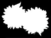
Fig. 3.44 Alpha channel of flower map.
Lamp. © Marcia Kuperberg 2001.
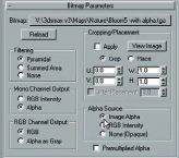
Fig. 3.46 Alpha setting turned on in 3DS Max Materials Editor
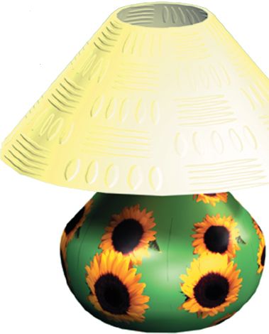
The table lamp: using alpha channels to create ‘cutout’ images on objects. The lamp base has a cutout image of flowers placed like a transfer onto its shiny green surface. The surface is a mid-green diffuse colour with the shininess and glossiness values increased to give it the effect of glazed ceramic. The flower pattern (fig. 3.43) is a map that has an alpha channel within the image (fig. 3.44) so that the blue background of the original image has been made completely transparent, allowing the underlying material of the lamp base, a shiny dark green, to appear under the cutout flowers. Notice that the flowers have been tiled (fig. 3.45).
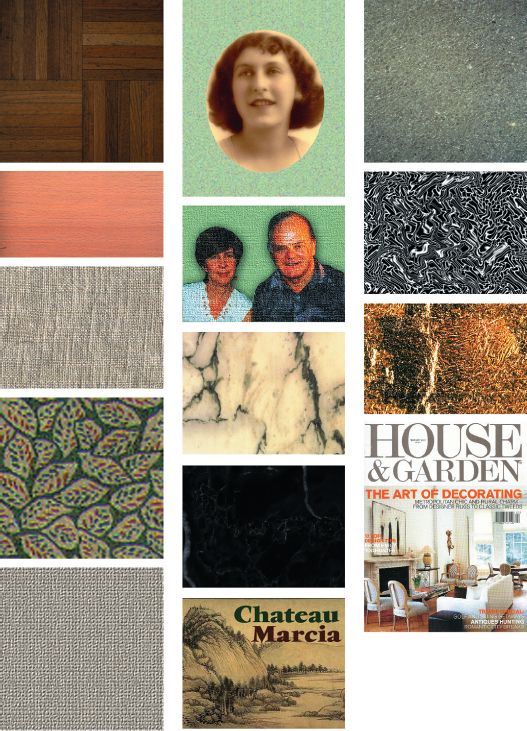
Fig. 3.47 All materials used in the room are shown here in their original untiled format. House & Garden magazine cover © The Conde Nast Publications Ltd. 2001.
How do you get an ‘alpha channel’? Once you have chosen your image, you must create an alpha channel for that image in an image editing program such as Photoshop (save a selection as a new channel and ensure that you save the image as a 32-bit image in a format that your 3D program can read). Only a few image formats will allow you to carry this extra channel, e.g. tif and tga. When making your alpha channel, all you need remember is that the part of the image that you don’t want to see – i.e. the part that will become transparent to allow an underlying object or material to show through – must be made solid black. The part of the image that you do want to see – i.e. in this case, the flowers – must be made white; your alpha image will consist of just solid blacks and whites (fig. 3.44), unless you want some of the image to be partly transparent – in which case you will use varying levels of grey, depending upon how visible you want these parts to be.
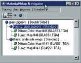
Fig. 3.48 This shows a hierarchy of levels used to create the material for the bird wings. A double sided material was used as the 2D plane would otherwise have been visible from only one side.

Fig. 3.49 Tiling and positioning of alpha flowers on the lamp base. Max’s shrink wrap UVW mapping co-ordinates were used.
When you turn on ‘Alpha’ in your 3D program materials editor, it will read the white part of the alpha as opaque and won’t therefore interfere with the flower part of the image at all, i.e. the flowers will be seen on top of the green base material.
• Techniques to minimize modeling. It is useful to take the time to experiment and practise how to use alpha and opaque masking in your 3D software, as it can be very useful not just in creating an effect like the one shown on the lamp base, but also in other ways, for example, the carpet fringe (fig. 3.2). For this, a mask was created (fig. 3.51) to be used together with the carpet texture (fig. 3.50). The label on the bottle (fig. 3.6) was an image scaled down (with a UVW modifier at sub-object level) which overlaid the diffuse dark red colour of the wine bottle. The dark red was given a high shininess value and a sharp specular reflection to create a glass look. To create the effect of the label and rug fringe through modeling would be time consuming and unnecessary.
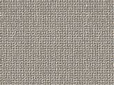
Fig. 3.50 The carpet texture.
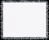
Fig. 3.51 The carpet fringe (fig. 3.24) was created using the opacity map shown here to mask out parts of the carpet.
Besides choosing an appropriate material that enhances your model, the trick to making your material look good is to:
• Place (project) the bitmap onto the model in the best way to avoid streaking or other unwanted artefacts. If your model part is a primitive sphere or a cylinder, your software will probably automatically apply the correct mapping co-ordinates – spherical or cylindrical. Planar mapping is usually the default and would be the most appropriate to use on flat objects such as the floor and ceiling. The lamp base is basically spherical but you will need to experiment with mapping co-ordinates to see which look best (fig. 3.45).
Very often, even though you are using the same material (say, a bumpy fabric) you need to apply the mapping co-ordinates manually and separately to each of the different parts of your model. This is almost certain to be the case if the material needs to be tiled and parts of the model vary considerably from each other in shape or size. Otherwise, the texture or pattern will appear the correct size and position on some parts but may be streaked, distorted or wrongly sized on other parts. Generally, it’s best to apply your mapping co-ordinates before deforming your model.
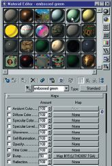
Fig. 3.52 Materials Editor of 3DS Max showing the use of a bump map to make the wallpaper effect.
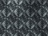
Fig. 3.53 This greyscale image was placed in the bump map slot in the materials editor above. It is shown in its original untiled format. The effect of tiling can be seen in the wallpaper in fig. 3.54.
As you know from Chapter 2, ‘co-ordinates’ (local or world) describe the placement of geometric objects in 3D space in the directions (axis) x, y, z. The corresponding terminology to describe placement of bitmaps onto models (and to differentiate these from co-ordinates used for geometry) is UVW. In the case of the sofa, UVW box mapping was applied to each part of the model separately before grouping the parts, with differing tiling on some of the pieces so that it looked as if the same fabric was used overall (fig. 3.9).
• Tile the material so that the pattern appears in the size and shape you want it – neither too big nor too small – (you can vary the tiling amount in both vertical and horizontal directions). The amount of tiling required (if any) will vary according to the size of the material map being applied and the size of each part of the model where the map is being applied. You’ll find the tiling parameters in the materials section of your software, and possibly also within the modeling modification section – the place where you indicate whether you will be applying UVW mapping co-ordinates to your model. Experiment and render a small image to check the effect of different amounts of tiling. Sometimes you may need to scale the bitmap, change its angle or its position on the model.
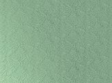
Fig. 3.54 The wallpaper texture after tiling.
• Experiment with different types of surface properties. Today’s 3D software is becoming more and more sophisticated. Even basic software will offer you a choice of rendering methods to render your materials, e.g. Blinn, Phong, Metal. Each will give a different effect to each of your materials.Max added Oren-Nayer-Blinn to its list of rendering types within the Materials Editor in release 3. Invented originally for a matt terracotta look, this gives a soft highlight sheen. It tends to make a material slightly deeper in colour when rendered but shows off fabric textures rather better than other types of rendering (figs 3.55 and 3.56). You may have to invest in third party rendering plug-ins such as Renderman, sometimes an expensive option.
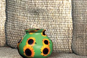
Fig. 3.55 Rendering with Max’s Oren-Nayer-Blinn shader.
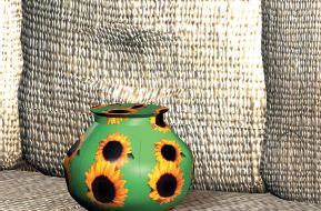
Fig. 3.56 The same scene with the same lighting but rendered with Phong shader. Notice the difference in the fabric highlights.
Images on this page © Marcia Kuperberg 2001.
PAYING ATTENTION TO LIGHTING YOUR SCENE
You’ll find it no surprise that lighting in computer animation is considered a real art, and is often a specialist field, much like modeling, texturing or character animation. In this respect, your 3D model is no different to a filmset where the lighting cameraman (the cinematographer) makes a huge contribution to the overall ‘look’ and atmosphere of the film – similarly the lighting designer in a theatrical production.
After all, what’s the good of selecting the perfect colour scheme for your room – pattern, texture, colour and contrast – if your lights bleach it all out or the shadowed areas are so dark, you can’t even discern that there is a pattern? When lighting your 3D scene, you are literally, painting with light. Described here are some of the different types of lights available in your software. Later in this chapter there are tips on lighting setups for your scene.
Types of lights
There are a number of different types of lights available to you depending on your software, and how much you can tweak them to give you very specific effects will vary with each program. Most programs will allow you the facility to exclude the chosen light’s effect from selected items in your scene, an extremely useful function. You can usually also click on a given object’s properties to exclude it from receiving shadows if you are using a shadow casting light. Too many shadows confuse the scene and increase rendering time. The most common types of computer lighting available are:
• Ambient lighting. This is the basic level of lighting available before you begin to add the types of lights listed below into your scene. In other words, it is the available light before you begin to ‘paint your scene with light’ from artificial light sources. It’s best generally to leave this at the default setting, probably black – as changing it can give you problems in adjusting other lighting later. If you wish to add atmosphere, say by making deep purple shadows for a stark moonlit night scene, adjust the shadow colour separately.
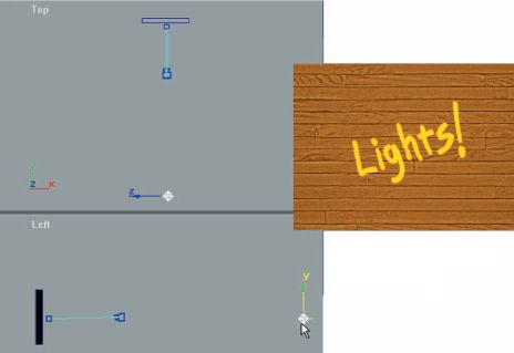
Fig. 3.57 Single omni light placed at a distance, lights the wall evenly.
• Omni lights – sometimes called ‘point’ or ‘area’ lights. These throw light in all directions like the sun. Unlike the sun and also unlike spotlights, omnis will usually shine right through walls and other objects. In some packages, omnis can also throw shadows, in which case their light is blocked by objects in their path. Check your own package to see what is available to you using omnis, e.g. the shadow casting properties, attenuation and decay.
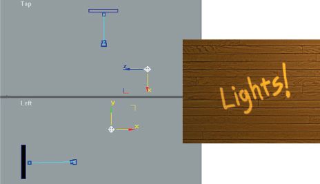
Fig 3.58 The omni light placed at an angle to the wall gives gradated lighting.
Images on this double page spread © Marcia Kuperberg 2001.
• Spotlights – targeted. You’ll be able to place the light itself within your scene and drag your mouse to place its target, i.e. where you wish it to point towards (the target is an indication of direction only – it doesn’t affect the light if you place it near your target, in it, or beyond it).
You have the option of whether or not to show a targeted spot’s directional cone with, perhaps, the option of a round or rectangular cast light. The latter is useful, if say, you want to light up a rectangular object such as a painting on a wall. Another useful option is one that lets you make one of your viewports into a spotlight view, i.e. as ‘seen by the spotlight’ (similar in principle to your camera viewport).
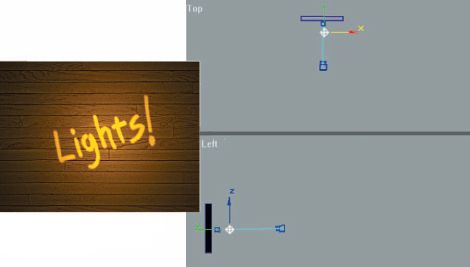
Fig. 3.59 The same omni, moved close to the wall, does not light evenly.
Spots have a ‘hotspot’: the centre and brightest part of the light that shows on the objects that are lit, and a ‘fall off’ – the area between the end of the hotspot where the light gradually reduces its brightness until it fades to nothing. The type of spot that lights up a performer on stage is normally a bright round circle with very little fall off (fig. 3.60). If you want a much softer effect, you will adjust your spot so that there is considerable difference in diameter between the hotspot and the fall off (fig. 3.61).
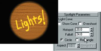
Fig. 3.60 Spotlight with bright hotspot and little fall off. No light falls outside the larger fall off ring.
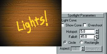
Fig. 3.61 Spotlight with smal hotspot and large fall off gives a much softer effect. No light falls outside the larger fall off ring which is slightly larger than the wall shown.
Spots can cast shadows and need to be placed at an acute angle in order to cast a longer shadow. A spot placed directly above an object will, like the sun, give a very small shadow around the base of the object.
• A free spot is similar to a targeted spot, but you angle the light itself to point toward an object, rather than placing its target near the object. This means it is harder to make it to point where you want, but a light like this has its uses, because you only have the light, itself, to adjust, rather than both light and target. This is useful in cases where the light is linked, say – to a camera that is moving along a path.
Another example might be headlights attached to a car. The linked lights would be casting associated moving spotlights according to where the car is heading.
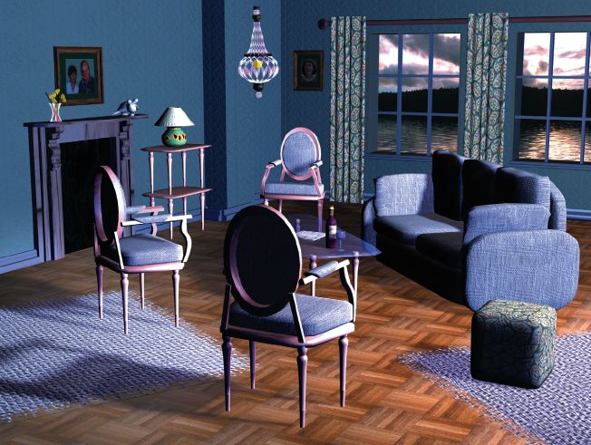
Fig. 3.62 Night scene of room shown in fig. 3.2. Lights have been given various blue tones as shown on following pages. See fig. 3.63 for basic lighting setup used here.
Images on this double page spread © Marcia Kuperberg 2001.
• Directional light is similar to a spotlight but casts a light in one direction only rather than in a cone from a point. It is useful placed at an angle, given a volumetric setting to simulate shafts of light through windows.
• Projector lights. These lights have the property of being able to project a bitmap or an animation. You could use the latter effect, for example, if you wanted to show moving images on a TV screen.
• Coloured lights. You can see from the evening scene that some lights have been given a blue tint to simulate dusk and to reflect the scene outside the windows. You can adjust any light to be coloured and cast its colour into your scene.
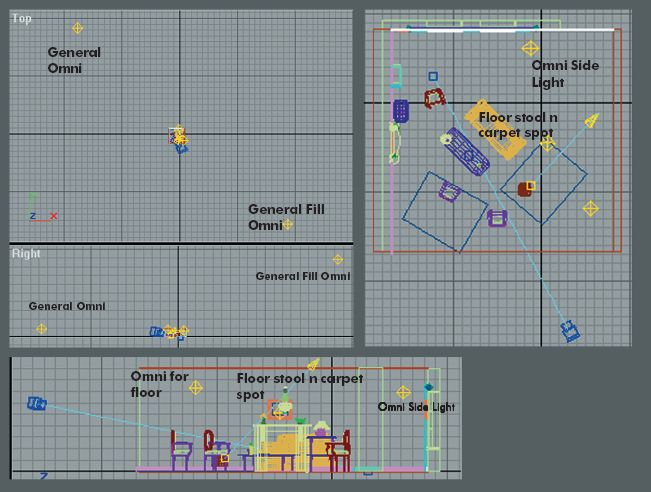
Fig. 3.63 Lighting setup for the scene in fig. 3.62.
Five lights have been used:
1. Omni Side Light (the main key light)
2. General Omni
3. General Fill Omni
4. Omni for floor
5. Floor stool n carpet spot
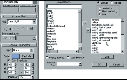
Fig. 3.64 Omni side light, the main key light for the scene. A number of objects have been excluded from its effects. It is a pale blue colour (see RGB settings), casts shadows, and is bright (with a multiplier of 1.5).
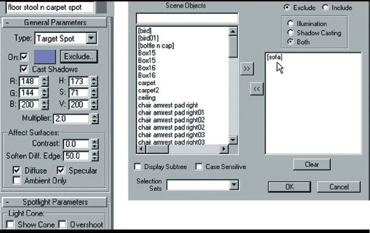
Fig. 3.65 Floor, stool and carpet spot. The purpose of this light is to throw a pool of light onto the carpet and enable the footstool to cast a long shadow.
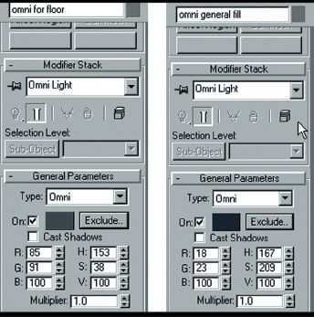
Fig. 3.66 Omni for floor, and Omni general fill lights. These two omnis serve the purpose of providing low level fill lighting for different areas. They do not cast shadows or carry a list of objects excluded from their effects. The omni general fill light is coloured blue.
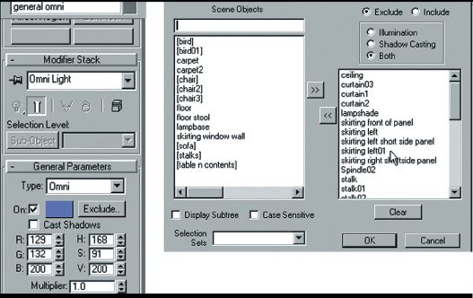
Fig. 3.67 General Omni light has been placed far from the main scene to spread light evenly (see the placement of lights in fig. 3.63) with many items excluded.
• Volumetric lights. When you sit in a cinema and you look back at the projection window, you’ll notice the beam of light from the projector towards the screen. Volumetric lights allow you to create a lightbeam, not just the end effect of the light on the surface of your objects. If your software gives you the facility to create this type of lighting, it will allow you to adjust the size/ shape of the beam (along the shape of the target spot shown as a cone or a directional light’s parallel lines in your viewports), the opacity of the beam, its colour and, in some cases, even the swirl of the particles of dust within it (using animated ‘noise’ effects). Like raytracing and other special effects, the use of volumetric lights slows down rendering.
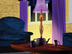
Fig. 3.68 The lamp has a self-illuminating sphere (the lightbulb) inside the semi-transparent shade and a volumetric beam to simulate the light cast by the lamp. A tiny omni has also been placed inside the sphere with its effect attenuated to cover a very small area inside the lampshade to give a brighter light to surround the lightbulb.
© Marcia Kuperberg 2001.
FINE-TUNING THE EFFECTS OF LIGHTS USED IN YOUR SCENE
Attenuation and decay. These are important features as they give you even greater control over the lights in your scene. Attenuation and decay settings control the fading out of lights over given distances.
When you are placing a number of lights into an interior, it becomes very easy for the scene to become over bright and ‘washed out’ unless you adjust the light’s multiplier (explained below), and reduce it to, say, 0.5, or attenuate the light to tone down its effect over chosen areas. Often you’ll also want to exclude certain objects from receiving light (fig. 3.67). In real life, we take the physical property of lights fading out over distance for granted. Your software will give you various settings to adjust this fade out; it is not automatic. The ‘start’ setting is the point where you want the fading out effect to begin. The light intensity will begin to fall off at the end of the far setting until the ‘end’ when there is no more light.
Your software will probably also allow you to utilize one of your viewports to view the scene from a given light’s point of view. This can be very helpful when deciding how much of the scene you want the light to affect.
Multiplier effects. Multipliers multiply an entered value in the RGB settings: the colour of the light appears to change together with its brightness. A value greater than zero increases the level of the light, while a negative value decreases it. Tip: if a corner of your room or scene is too bright, and nothing else works, you could add a light to decrease the light, by using a negative multiplier in the light’s parameters. Try it out: it can be a life saver!
Shadows. In some programs, all lights can cast shadows; in some, only spots cast shadows. You must be judicious when deciding which lights should cast shadows, not only because shadows increase rendering time, take up memory (RAM) but also because too many shadows crossing each other in different directions will cause visual confusion in your scene. No use of shadows at all, on the other hand, will make your scene appear artificial; your objects may look as if they are not properly anchored onto their surfaces.
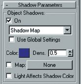
Fig. 3.69 Shadow parameters (3DS Max) used for the floor, stool and carpet spotlight (fig. 3.65). This light’s main purpose was to cause the footstool to throw an oblique shadow and to light the carpet nearby. Initially the shadow was too harsh and prominent, so the density was lowered by half to 0.5 and the effect further softened by colouring the shadow blue.
Your software will give you considerable flexibility both in the types of shadows your lights can cast and in the ability to exclude chosen objects from casting or receiving shadows. You thought shadow casting was just a matter of clicking on/off a radio button (of a selected light) that says ‘shadows’? Wait till you delve a little more into your software manual and find out just how many types of shadows there are, and how you can tweak and adjust their parameters for artistic effect – bet you never realized that shadows could vary so much!
Raycast shadows can give you the type of hard-edged shadows cast by the sun on a bright day (fig. 3.70). They are very accurate in terms of the physics of the scene, but take a long time to render relative to non-raycast shadows.
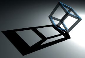
Fig. 3.70 Sharp hard-edged shadow. Image courtesy of Advanced Rendering Technology Ltd.
Other images on this double page spread © Marcia Kuperberg 200
If you have a light shining through a glass object, and you want the shadows cast by the object to look realistically translucent you will require raycast shadows to achieve this effect. Similarly, an opacity map, or a map with alpha to create holes in your model will also require raycast shadows, or will give the game away with solid ‘no hole’ shadows.
Many programs also allow you control over the colour, density and texture mapping of shadows. Very sophisticated programs can even give you ‘caustics’ – the sort of effect you get with dappled sunlight at the bottom of a swimming pool. But if your program doesn’t have caustics, you can fake the effect by using a projector light with animated noise (look up how to do this in your manual or online help). See Chapter 8 for more.
You’ve experimented with different types of lights. The example of the starkly lit evening scene of our room is demonstrated here but of course there are many approaches to lighting a scene. You could try using the time honoured way of professional lighting cameramen on filmsets: the three-point system. This consists of a key light which is the main light in the scene and usually the one given shadow casting properties. This could be placed behind the camera, elevated to look down on the subject but to one side of it so that the lighting is not flat but shows the three-dimensional character of your model. On the opposite side, place a ‘fill’ light at a much lower level than the key light, so that this area of the model is not in total shadow. Then, behind the model, place a backlight to differentiate the main parts of the scene from the background. Try using a lower multiplier with larger attenuation so your lights don’t spread further than you want. You may also need to exclude certain objects from receiving the light and/or the light’s shadows (fig. 3.67)
You can apply this method to your whole scene, or just an area within it – lighting another zone elsewhere in a similar way. You can turn lights off and on, once you’ve created them to check each effect by rendering the scene from your camera viewport, so don’t tweak everything all at once. Don’t use an approximated rendering as it may not be accurate. Tip: to speed up rendering to check lighting, turn off antialiasing and render a smaller image size. Don’t forget to turn the correct settings back on for the final render!
You could simply light your scene with a large number of omnis, grouped in threes with attenuation set so that the lights only affect small chosen groups or even single objects. Alternatively, you could use a combination of lights: omnis to give the overall basic light to a scene, plus spots carefully placed close to selected objects to give the lighting and shadows required. You can also get very dramatic and unusual effects by lighting from below or with the key light for backlighting and gentle fill lights placed front and side.
Lighting is an art. Experiment!
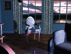
Fig. 3.71 Camera lens 50 mm.
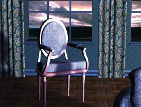
Fig. 3.72 Telephoto lens 85 mm.
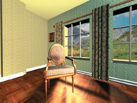
Fig. 3.73 15 mm lens, FOV: 100.
Images on this page © Marcia Kuperberg 2001.
Types of camera. It is likely that your software will give you the choice of using a free camera or a target camera. This is similar in many ways to using free spotlights or target spotlights. You’ll mostly use a target camera as it is the easiest way to angle the camera to view the scene as you want. The free camera has to be angled without the aid of the target to point at the object, but it comes into its own when it has to follow a path and it can ‘bank’, i.e. rotate to balance itself as it enters and turns around the curves of its set path.
As with real cine or video cameras, you can move your virtual animation camera in many ways and in addition your software will offer you a range of virtual lenses that mimic real life ones, plus an infinite number of other focal lengths. Lenses, like those in real cameras, are measured in mm.
A 50 mm lens corresponds most closely to human vision (fig. 3.71); lenses shorter than 50 mm are referred to as wide-angle lenses and those longer than 50 mm are called telephoto lenses. The same scene with the camera placed in the same position but using a telephoto lens of say, 85 mm shows the scene in close-up, giving a foreshortened ‘flattened’ effect (fig. 3.72). If you want to exaggerate the perspective, use a wide-angle lens and adjust the field of view (FOV) to give you the desired effect (fig. 3.73). In general, wide-angle lenses are used for ‘establishing’ shots – to set the scene and familiarize the audience with the location – and close-ups are used to centre the audience’s attention on some aspect of the scene or action.
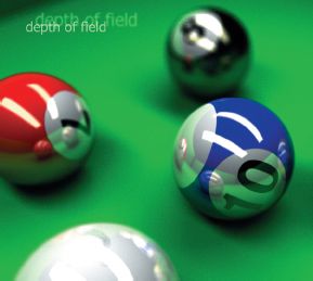
Fig. 3.74 Depth of field. Image © Simon Clarke, Advanced Rendering Technology Ltd.
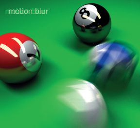
Fig. 3.75 Motion blur. Image © Simon Clarke, Advanced Rendering Technology Ltd.
Simulating photographic effects. Many animators like to do this by applying filters or rendering techniques to give out-of-focus or motion blur effects (figs 3.76 and 3.77). Also see examples in Chapter 7 (e.g. fig. 7.16). There are a number of ways to do this, depending on your hardware and software. You can also use compositing techniques in software such as Adobe After Effects. See Chapter 6 for examples of this (figs 6.65–6.70) and Chapter 8 for further resources.
Camera framing and movement are among the important tools that the filmmaker uses to convey drama and narrative. Read Chapter 7 for using your camera creatively in a narrative and for more on characterization.
You have the option to set up a number of cameras, each with the lens and view of your choice, though you can only use one at a time. The benefit of creating more than one camera is that you can try out different views and camera lenses and angles as alternatives and return to those that you like best.
• Zoom/FOV. The camera remains static but the FOV (field of view) changes from long shot to close-up or vice versa.You set keyframes for your zoom angles by clicking on the FOV or zoom button at a particular frame and then adjust your camera view by the same means at a later point in the action, letting your software fill in the in-between frames to achieve the zoom in or out. The perspective of the whole scene can change according to the zoom setting you choose and the FOV. See examples: figs 3.71–3.75.
• Dolly. This gives a different effect to the zoom, as the camera itself moves forward or further away from the object, rather than the lens effect of the zoom.
• Panning. This is similar to when the camera is mounted on a tripod and is slowly swivelled from one side to the other.
• Trucking or tracking. This is similar to panning, except that the camera, itself, moves – it’s like a horizontal form of orbiting with the camera on wheels.
• Orbit. The camera moves in a circle, i.e. orbits its target.
• Tilt and rotate. If you want complete freedom to rotate and tilt your camera about any axis, it is better to create a ‘dummy’ or ‘null’ (i.e. non-rendering) object that you can move and rotate as you want, and link a free camera to it. Target cameras can only rotate around their local Z-axis. The dummy will act as a parent to the child camera in this hierarchy and give you greater movement flexibility.
• Safe frame. Having set up a camera in the scene, set the safe frame facility on your camera viewport to the aspect ratio of the final output medium, e.g. for video it might be 4 × 3 or wide-screen (fig. 3.78). The reason for this is that the image shown in your computer monitor’s viewport will show a greater area of your image than a television screen. The TV screen ‘wraps’ the image around the edges, and different screens vary with the amount of cutoff on different sides. The only way to be safe is to ensure that titles or other important parts of your scene fall well within this ‘safe frame’ or safe titling area. This applies if you intend to render your animation, lay it off to video and then show it on a video monitor or television screen. If you want a colour print of your scene, the printer will disregard the cutoff.
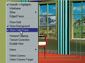
Fig. 3.76 Safe frame is the inner rectangle. Images inside this area will be safely in view on the TV or video monitor. The reason for this ‘safe frame’ inner rectangle is that televisions and some monitors cut off part of the image that is normally seen in full on a computer monitor. Staying well inside the safe area is particularly important for text and titling for video or TV output.
When you print a scene from one of your viewports, the printer will show the full outer rectangle.
© Marcia Kuperberg 2001.
USING YOUR CAMERA TO EXPLORE THE ROOM
As there are no characters currently being animated in our room, it provides a good opportunity to let the viewers absorb the scene through the eye of the camera. Even with a simple scene like this, with no characters to animate, any movement of the camera will either be telling a story or ‘setting the scene’ for a story to begin. Someone going into a strange room might quickly glance here and there, but doing the same thing with a camera will give a ‘hosepipe’ effect.
You are the director and you will skilfully guide the viewers around the scene, hopefully without their being conscious of your guiding hand – all this through the framing and movement of your camera. Ideally, the camera movement should be smooth and unobtrusive, allowing viewers to absorb what you, the director, want them to see and absorb.
We could begin by looking out of the window, and then gently pull back while panning across the mantelpiece before pulling back further to see the room in long shot (fig. 3.77).
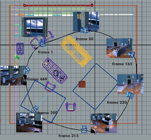
Fig. 3.77 Top viewport. Here a target camera is following the path and its target is linked to a ‘look-at’ non-rendering dummy. The total animation is 500 frames. The inset images show the camera’s view at various frame numbers along the path.
Decide how many seconds you want your camera movement to be and set the relevant number of frames. Then turn on the animate button (in Max – use the equivalent in your software) and frame your scene in the camera viewport at each key change of camera position in the total timeline, thus setting up your camera keyframes. When doing this, take care that you don’t raise or lower the camera or its target much from one key position to the next, or you will make your audience seasick! Render a test animation at low resolution. Your first effort may create camera movement that is way too fast, and not nearly as smooth as you would like. Your next step is to examine the camera’s path, i.e. the trajectory that was created by these moves (in Max, you select any object – in this case, the camera – and view its path in the Motion section of the modifier panel). You may need to cut some keyframes.
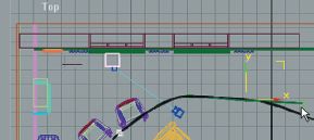
Fig. 3.78 The camera’s trajectory has been converted into an editable spline with bezier curves. The shape can now be manipulated via the handles just like any other spline.
The fewer the keyframes, the smoother and more natural the camera’s motion will be. Your software may allow you to smooth the shape of the trajectory by converting it into an editable spline (fig. 3.79) or into a NURBS curve (NURBS curves are always smooth). If you convert to an editable spline, you’ll be able to treat it like any other shape by going to the sub-object vertex level to use handles that you can manipulate to smooth the curve and give you the shape you want. Then, convert the spline back again to become the camera’s new trajectory. If the camera’s movement is too fast or slow you can slide keyframes along the timeline or along the path (fig. 3.80) to increase or reduce the number of in-between frames. You will probably also be able to tweak further by manipulating the type of movement between the keyframes affecting the slow-in/slow-out, sharpness or smoothness of movement (see figs 5.32–5.34 in Chapter 5).
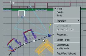
Fig. 3.79 Here the trajectory has been ‘collapsed’ into a path with the keyframes visible. Keys can now be selected and moved.
Images on this page © Marcia Kuperberg 2001.
Following a set path. An alternative that may give a more professional result is to draw a NURBS spline path in the top viewport and elevate it in the front or side viewport to gain the view desired. ‘Tell’ your software that the (free or target) camera should ‘follow’ this path. If you create a non-rendering dummy/null object that is linked to the camera’s target (parenting the target), you can make your camera ‘look’ at the dummy which you place and animate, while the camera follows merrily along its path.
Rendering. If you’ve created your own room and animation, well done! Now refer back to Chapter 2 for information on rendering and read Chapter 8 for more 3D briefs. Have fun!
