

Most digital compositors work with video, a perversely complicated medium. This complexity comes from the need to compress the video information as much as possible to lower the data rate for broadcast. This compression takes many forms and introduces issues and artifacts that we have to cope with when compositing visual effects in video. If you understand how the medium works you can prevent many problems from being introduced in the first place.
If you are working with a dedicated video system such as Flame it has design features built into it to make many of these issues transparent to the artist. However, if you are working with a “desktop” compositing system then you will most likely have to manage these issues yourself. This chapter is not so much about the theory of video as it is about the practical aspects of working with it in a visual effects shot. It describes the issues that cause trouble, and then offers workflow solutions to help you get around them.
11.1 SDTV (STANDARD DEFINITION TELEVISION)
SDTV is the digital television standard that you may know as NTSC and PAL. The picture aspect ratio is 4 × 3 (or 4:3, or 1.33, or “133”) and the video is interlaced—an irksome concept we will tackle in the very next section. SDTV is messy and full of noxious complexities that make digital compositing much more difficult than it should be. The reason that it has all of these peculiarities is because they were needed in the early days of television in order to lower the amount of data required to broadcast a frame of video. Once designed into the specifications, we were stuck with them. Following, then, are explanations of these noxious complexities along with strategies on how to cope with them. There is a lot of coping here.
11.1.1 Coping with Interlaced Video
You need to understand interlaced video because you will often have to get rid of it before you can work on a shot. In this first section we are only concerned with understanding what interlaced video is and how it works. In later sections we will see how to de-interlace video.
The video frame is made up of a series of horizontal scan lines, but unlike film where a frame is a frame, with video a frame is made up from two fields. Each field contains half the scan lines of the frame, with field 1 holding the odd scan lines and field 2 the even scan lines. When these two fields are merged, or interlaced, like the illustration in Figure 11-1, they make up one frame of interlaced video. The illustration in Figure 11-1 is made up of exaggerated scan lines to make the process easier to see.
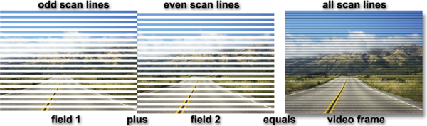
Figure 11-1 A frame of interlaced video is composed of two fields
For NTSC television there are 30 frames per second (PAL has 25) and since each frame is made up of two fields it means there are 60 fields per second (50 for PAL).
A video camera actually scans the scene from top to bottom twice each frame, first all the odd scan lines then all the even scan lines. This means each field captures a different moment in time. This is the basic problem with interlaced video. Two different moments in time are merged together in each frame so the picture information is not “temporally coherent.”
Here is a thought experiment to help envision interlaced video. Think of a film camera with its shutter. It captures one frame per shutter, and does this 24 times per second. Simple. Now imagine that we have an “interlaced” film camera that has two shutters and two rolls of film. Both shutters expose the film at 24 frames per second, but they alternate—when one is open the other is closed. The two shutters together are now capturing 48 frames of film every second. Now take all the odd scan lines from one roll of film and merge them (interlace them) with the even scan lines from the other roll of film to get back to 24 frames per second. You now have interlaced video—it’s just at 24 frames per second instead of 30. But you also have two moments in time per frame.
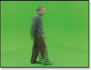
Figure 11-2 Horizontal motion
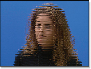
Figure 11-3 Vertical motion
Figure 11-2 illustrates what happens when something moves horizontally with interlaced video. The character is in two different positions for each of the two fields because, again, each field is a different moment in time. (To see a movie illustrating this horizontal affect download www.compositingVFX.com/CH11/Figure 11-2.mov) Figure 11-3 shows the equally bizarre effect of vertical motion in an interlaced system. (To see a movie illustrating this vertical affect download www.compositingVFX.com/CH11/Figure 11-3.mov)
You cannot run a blur or perform a rotate or scale on interlaced images like this. Any operation that filters adjacent pixels results in a horribly disfigured image because the two sets of scan lines become garbled together.
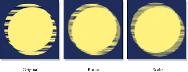
Figure 11-4 Transformations done on interlaced images
The garbled scan lines from transformations are shown in Figure 11-4. The original image on the left is a closeup cropped out of an interlaced video frame. Note how clean and distinct each scan line is. The middle frame shows what a rotate of just 2 degrees does to the interlaced scan lines. In some areas the scan lines are completely blurred away. The scale example on the right shows the damage caused by scaling the original image up by just 2%. There are more regions of blurred scan lines.
Before any of these types of operations are performed the video frames must be de-interlaced so that each frame represents one moment in time. This discards one of the fields, and then replaces it by interpolating the scan lines of the remaining field. All modern compositing programs have video de-interlacing features. However, if you are only performing operations that do not filter adjacent pixels, such as color correction, then there is no need to de-interlace.
There are two different interlacing cases. The first case is where the video was captured with a video camera. In this situation every single frame will show interlaced scan lines and the shot will need de-interlacing. The second case is where a film was transferred to video. This results in only some of the frames showing interlaced lines. This case does not require de-interlacing, but simply a 3:2 pull-up, which is described in its own section below. Before you start any de-interlacing you need to confirm which type of video you have—a video capture or a film transfer. (To see a movie with serious interlacing download www.compositingVFX.com/CH11/interlaced video.mov and single step through it.)
11.1.2 Coping with Non-square Pixels
One of the more pesky issues when working with SDTV is its non-square pixels. Because of this the picture you get on your workstation does not look like what you saw on the TV screen. This subject was touched on briefly in Chapter 2. On the TV screen the pixels are squeezed horizontally by 10% so they are tall and thin like the illustration in Figure 11-5. When this image gets to your workstation its monitor has square pixels so the image suddenly pops wider by 10%. The number of pixels is the same; it is their shape that has changed, so the shape of the displayed image changes. Circles on the TV screen become ovals at the workstation. Figure 11-5 illustrates how the image appears wider on a workstation monitor than on the TV screen due to the non-square pixels.
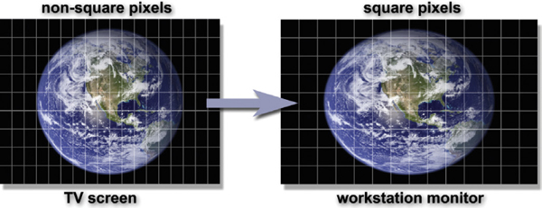
Figure 11-5 An NTSC image stretches by 10% when viewed on a workstation monitor
In most situations you can ignore the fact that the video frames are stretched by 10% on the monitor. You can just do your thing, then put the finished shot back out to video. The TV screen will squeeze the images back where they were and all will be well. If you do need to correct for the non-square video pixels then first de-interlace the video, and then resize the video frames from 720 × 486 to 720 × 540. This will create a “square pixel” version for you where a circle is a circle, not an ellipse. Figure 11-6 illustrates this workflow. If the finished results are to go back to video, then resize the frames back to 720 × 486 and re-interlace.
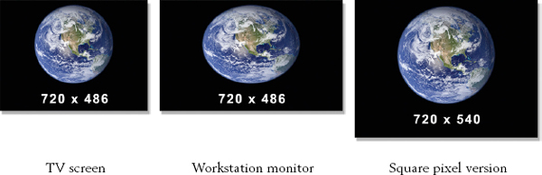
Figure 11-6 Squaring the pixels on a workstation
If you are creating a brand new element for SDTV such as a station graphic or digital matte painting you will want to work in the “square” resolution of 720 × 540, then resize to 720 × 486 before sending it off to video. If you don’t, your circles will become squeezed horizontally by 10% and become noticeably elliptical.
PAL squeezes the pixels in the vertical direction, so when a PAL image goes to a workstation the image pops vertically by 10% instead of horizontally like NTSC. The PAL video frame resolution will be 720 × 576, so to square it the width must be increased to 768 × 576. If creating a PAL image, build it at 768 × 576 then resize it to 720 × 576 before sending it to video.
11.1.3 Coping with Color Sub-sampling
Yet another data compression scheme used in video is color sub-sampling. The idea is that the human eye is very sensitive to brightness (luminance) detail, but not so sensitive to color detail, so why transmit color information that nobody cares about? The video camera captures an RGB image, but it is converted from three channels of red, green, and blue to a YUV image. Still a three-channel image, the YUV image has the luminance in the Y channel and the chrominance information divided between the U and V channels.
Now here’s the rub—the U and V (chrominance) channels are digitized, or sampled, at half the resolution of the Y (luminance) channel—again, because the eye doesn’t care and we need the bandwidth. For every 4 digital samples of the Y channel there are 2 samples of the U and 2 of the V. This sampling scheme is therefore known as 4:2:2 to remind everybody that the UV chrominance is sampled at half the resolution of the Y channel. The 4:2:2 sampling scheme with its half resolution chrominance information is illustrated in Figure 11-7. (To view a high resolution version see www.compositingVFX.com/CH11/Figure 11-7.tif)
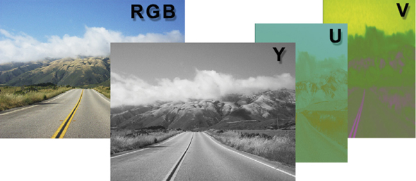
Figure 11-7 YUV image with 4:2:2 sampling
When a YUV image is loaded into a workstation the compositing program converts it to RGB so you can work with it in normal RGB color space and display it on your RGB monitor. The important thing to realize is that this RGB image has made-up pixel colors based in interpolating the U and V information. It has been stretched horizontally then combined with the Y information to make the RGB image.
This arrangement is fine for normal digital compositing operations—until you need to pull a key on a bluescreen (or greenscreen). The eye may not care about the half resolution color in 4:2:2 sampling but your digital keyer does. The keyer is trying to use the color information in the image to create a matte, but the color information is half resolution. This makes for bad mattes. It gets worse.
4:2:2 is not the worst-case; it is the best-case. There are other video standards out there which sample the chrominance even less. They are known as 4:2:0 and 4:1:1 sampling, and there are others, each worse than the last. The client should not be trying to shoot bluescreens with these low-quality video cameras, but they will anyway because the cameras and tapes are cheap, the pictures look OK on their monitor, and they don’t know any better. Usually by the time you get involved the video will already be shot so all you can do is grin and bear it.
Figure 11-8 Bluescreen RGB channels
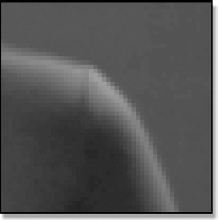
Figure 11-9 Y channel of the YUV version
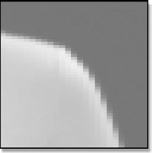
Figure 11-10 UV channels of the YUV version
There is one little trick that you can use which can help with the sub-sampled color when pulling a matte for a bluescreen shot, and that is to add a gentle blur to the UV channels. We will use the closeup of the bluescreen in Figure 11-8 as an example. The first step is to convert the bluescreen RGB image to YUV. You can now see the difference in horizontal resolution between the Y channel in Figure 11-9 and the UV channels in Figure 11-10.

Figure 11-11 Comp with original bluescreen
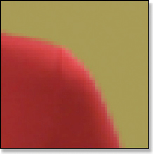
Figure 11-12 Comp with blurred UV channels
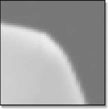
Figure 11-13 Blurred UV channels
Next, give only the UV channels a gentle blur like the example in Figure 11-13. Be sure not to blur the Y channel. We need all of its detail for the keyer. Now convert the blurred UV version of the YUV image back to RGB and present it to your digital keyer. The example in Figure 11-11 shows a composite using the original bluescreen from Figure 11-8. You can see a noticeable improvement between it and the blurred UV version in Figure 11-12. It’s not perfect, but it can help.
There is such a thing as 4:4:4 video, which was actually developed for the demands of visual effects shots. It is, in effect, a true RGB video with equal information for the luminance and chrominance channels. If you should be so lucky as to get a hold of any of this video you will find it does not have any of the color sub-sampling problems we have seen here and it should be a joy to key—for video.
11.1.4 Coping with Edge Enhancement
Tragically, there is no coping with edge enhancement. It is a built-in feature of video cameras that applies a sharpening filter to the video image, which creates an edge artifact that wreaks havoc with a keyer trying to pull a matte on bluescreen or greenscreen. Figure 11-14 shows the original greenscreen, a normal red channel, and a sharpened red channel. (To view a high resolution version see www.compositingVFX.com/CH11/Figure 11-14.tif)
The sharpened red channel has an arrow pointing out the artifact, which is the bright line around the outer edge of the character. Depending on the colors in the picture it can be a dark line. As far as the keyer is concerned, there should be no lines at all.
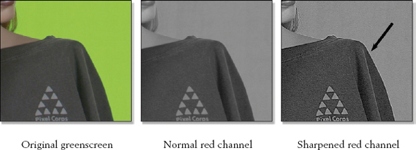
Figure 11-14 Edge enhancement artifact
When bluescreens are captured on video the edge enhancement feature of the video camera must be turned off to avoid introducing this edge artifact. It disturbs the true relationship between the color channels right at the critical edges causing the keyer to get confused and introduce its own edge artifact into the composite. One possible solution is to try some plug-ins that have been developed that claim to be able fix the problem. The best fix is not to put the artifact in the picture in the first place.
11.1.5 Coping with Frame Rates
It is often said that NTSC video has a frame rate of 30 fps (frames per second), but of course, this isn’t really true. Its true frame rate is 29.97 fps. The original black and white TV used to be an honest 30 fps, but when the color signal was added back in 1953 they had to shift the signal 0.1% slower to solve a natty technical problem. This has introduced a problem for the rest of us—confusion. True 30 fps and 60 fps video standards have recently been added for SDTV. The problem is that some equipment and software manufacturers label their buttons and knobs as “30 fps” which now might be either a true 30 fps or simply shorthand for 29.97. When working with software that has a pop-up menu listing a selection of frame rates and you see both 29.97 and 30 you can assume the “30” choice is an honest 30 fps.
We all know that film runs at 24 fps, but sometimes you will see something labeled as 23.98. The film does run at an honest 24 fps in the movie theater, but when it gets transferred to video the film’s 24 fps has to be converted to NTSC’s 29.97, not 30 fps. This means that the film’s 24 fps will be 0.1% slower, which comes out to 23.98 frames of film per second.
PAL does run at an honest 25 frames per second and there is no slick way to retime the 25 fps into NTSC’s 30 fps. When 24 fps film is transferred to PAL the film is simply transferred frame to frame so it ends up running at 25 fps on TV. This speeds the movie up by 4%, but nobody notices. This does raise the pitch of the sound track noticeably but that is an easy fix.
11.1.6 Coping with Timecode
While we look at the length of a shot in terms of its number of frames, video people measure their work in time and frames—so many hours, minutes, seconds, and frames. This they call timecode and it is written thus—03:20:17:12—which is read as three hours, 20 minutes, 17 seconds, and 12 frames. You need to know this because the client may hand you a videotape and simply tell you that the shot you are to work on is located at 03:20:17:12, so you will have to know what that means.
Another side effect of the 29.97 frame rate instead of the honest 30 fps cited above is that the timecode for video drifts off from real time. At an honest 30 fps there would be exactly 108,000 frames of video in one hour. But at 29.97 there are actually only 107,892 frames in an hour—a difference of 108 frames per hour. Because timecode is really counting frames of video, these extra 108 frames mean that an “NTSC hour” would run 3.6 seconds longer than a real hour. We can’t be having that when broadcasting a television show. This just keeps getting better.
The brilliant solution is drop-frame timecode. To keep the slightly slow-running timecode clock in sync with real time they wait until the timecode is almost one full frame behind real time, then skip (drop) the next timecode to catch up. So in one hour 108 timecode frames will be dropped out so the show will display a timecode of exactly one hour when the clock says one hour is up. Sometimes you will be given a videotape that has non-drop-frame timecode, which is more appropriate for production and visual effects. If a videotape has non-drop-frame timecode you should find “NDF” in big letters on the label somewhere. If it is drop-frame they should put “DF” on it.
11.2 HDTV (HIGH DEFINITION TELEVISION)
We now leave the murky world of SDTV and step into the bright sunlight of HDTV. The first thing you will notice is the spectacular increase in the size of the picture. Figure 11-15 compares the same image content displayed on two different video monitors of equal screen resolution. The HDTV picture has more than two times as many scan lines as the SDTV picture and it is widescreen, like a movie. In fact, the primary design intent of HDTV was to make it more compatible with feature films not only in aspect ratio but frame rate and picture information content. Unfortunately HDTV retains the same 4:2:2 color sub-sampling established by SDTV.
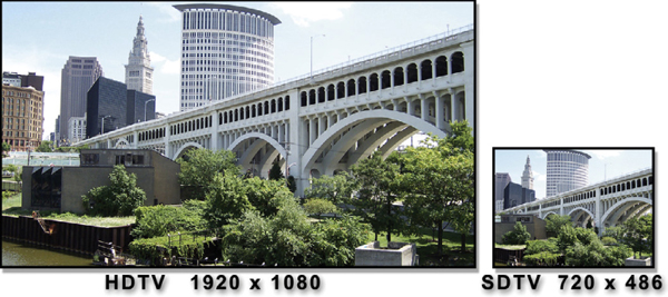
Figure 11-15 The mighty HDTV picture compared with the puny SDTV picture
The important thing about HDTV is that it is not just a standard; it is a family of standards. In it one can mix and match the image size, scan modes, and frame rates. But the really big news is that all HDTV standards specify square pixels—no more squeezing and stretching video images! Another constant with all HDTV standards is the aspect ratio, which is 16 × 9 (or 16:9). If you do the math it comes out to an aspect ratio of 1.7777777…Some will refer to it as “177” and others will call it “178,” depending on whether they prefer to truncate (1.77) or round off (1.78). We now take a look at the family of standards for HDTV.
11.2.1 Image Size
HDTV supports two high-resolution image sizes: 1920 × 1080 and 1280 × 720. In video slang the 1920 × 1080 will be referred to as “1080” and the 1280 × 720 as “720.” In each case they are citing the number of scan lines in a frame. Since the aspect ratio of HDTV is fixed at 1.78 for all standards, declaring the number of scan lines unambiguously defines the horizontal resolution so it need not be stated. We just know.
11.2.2 Scan Modes
There are three scan modes in the HDTV standards. Tragically, one of them is interlaced, as we saw above. The good news is that there is a progressive scan mode, which works exactly like a scan mode should. It starts scanning the frame at the top and works its way to the bottom, one line at a time. The really good news is that a great majority of HDTV folk use the progressive scan mode, so your chances of running into interlaced HDTV are fairly low. Why the progressive scan is preferred will be revealed below in “The 24P Master” section.
The third scan mode, Progressive Segmented Frame (abbreviated PsF), is in actuality a progressive scan mode and its images would be identical to those captured with the normal progressive scan. The differences are internal to the camera and videotape, so we don’t need to worry about it. I just didn’t want you to go blank if someone started talking about their PsF video.
11.2.3 Frame Rates
Technically, HDTV supports all of the frame rates in the known universe. However, in the real world (where you and I work) you are most likely to only see 30 fps and 24 fps HD video. OK, someone could throw some PAL at you at 25 fps, but that’s about it. Of course, HDTV also supports 29.97 and 23.98 frame rates. Fortunately, when working on a visual effects shot we are concerned about the frame count, not the frame rate. We are going to take 100 frames in and put 100 frames out. The precise frame rate only becomes an issue when it is laid back to videotape.
11.2.4 Nomenclature
With the array of HDTV standards available it becomes very important to be specific when describing the particular format of a given production job. To do that we need some official nomenclature in order to sound like professionals. If we are talking about an HD (HDTV) project that had a resolution of 1920 × 1080, progressive scan, at 24 fps, it would technically be known as 1080/24P (scan lines, frame rate, scan mode). If the project were the same resolution but an interlace scan at 30 fps (like NTSC) then it would be described as 1080/30I. Some would even shorten these to “1080p” and “1080i.” Of course, you could encounter a 720/25P or a 1080/60PsF, but those are fairly uncommon.
One of the downsides of all this wonderful digital TV technology is that it leaves a lot of room for mischief on the part of the camera manufacturers. While they cheerfully declare their video equipment to be “HD” the actual optical sensors and captured image data may be much less than 1920 × 1080 and simply scaled up to that size for display. Cheat! And we have already seen how they can fudge the color with 4:2:0 and 4:1:1 color sampling. Another cheat!
One other cost-saving shortcut on the part of the video equipment manufacturers is anamorphic HD. The camera captures a 1440 × 1080 image which is squeezed horizontally by 25%. This is then stretched when it is displayed on the TV screen (see Figure 11-16). This is done to save money on the cost of the video equipment. Not only are there fewer pixels in the optical sensor and image processing hardware but the data rate from the camera to the video recording equipment is lower, which makes it cheaper to produce as well.
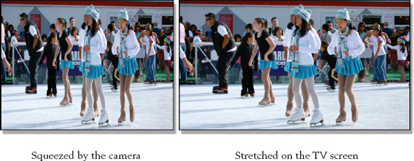
Figure 11-16 Anamorphic HD images
This introduces three problems for the dauntless compositor. First, since the image is under-sampled (it only has 1440 pixels horizontally instead of an honest 1920) we have less picture data to work with. Less picture data means poorer quality composites. Of course, the client will blame the hapless compositor for any poor results. After all, the original video looks fine on the monitor, right?
The second problem is the proper display of the picture. Some software programs can read the file header of the video clip and properly stretch it up to fill the screen, making it look normal. Other software may not be so smart and will display it exactly like it was photographed—squeezed, like Figure 11-16. This can cause confusion and consternation on the part of the compositor if he is unaware of anamorphic HD.
The third problem is that working with an anamorphic image with a pixel aspect ratio of 1.33 is much messier then a square pixel image. If your compositing software is hip enough to understand the anamorphic video format it will compensate for the non-square pixels “automagically” and you will have no trouble. If not, then you will have to manage the problem yourself. We saw in Section 11.1.2 Coping with Non-Square Pixels the hassles that this can introduce.
We love HD because it has square pixels, so what is going on here? The answer is that anamorphic HD is not a legal HD broadcast format. This is a “production” format. The video equipment manufacturers can abuse the video any way they wish between their camera and their video recorders, but when it is delivered for broadcast it must be converted to conform to one of the standards listed above. The problem is that we are in production (post-production, actually) and may be given video like this to work with. And the tragedy is that the nice client that gave it to you probably had no idea that his equipment is producing anamorphic HD. If he did, he would not be trying to use if for visual effects.
11.2.6 The 24P Master
Today, when a feature film is transferred (mastered) to video, it is transferred to the 1080/24P HDTV standard. When a television show or movie is captured in HD it is usually recorded as 1080/24P. The 1080/24P standard has become so pervasive it has developed its own shorthand name—24P.
24P has become the de facto HD standard for one simple reason—all of the many video variants can easily be made from this one master. First of all, it is 1920 × 1080 so it is the highest resolution. Any other version you wish to make will be equal or lower resolution. Second, because of the progressive scan and the 24 fps frame rate new versions can be made that are 24 fps, 25 fps, and 30 fps.
So how do you make a 25 fps video from a 24 fps master? Simple—just play it back at 25 frames per second. This is what our PALs in Europe have been doing with the 24 fps feature films for the last half century. Sure, the movie plays 4% too fast, but nobody notices. Also, the sound does jump up in pitch a bit, but that’s an easy fix in the audio sweetening department.
To make a 30 fps video out of a 24 p master is also easy—just transfer it with a 3:2 pull-down as if it were a feature film. We will learn more about how the 3:2 pull-down works shortly, so please stand by.
11.3 TITLE SAFE
Sometimes the digital compositor gets tapped to add some titles to a project, so you must be prepared. One of the key issues for titles is knowing where “title safe” is—the rectangle within which the titles need to fit. There is no official SMPTE spec for title safe—it is more like an industry standard practice. Title safe is quite different for SDTV and HDTV, as you can see in Figure 11-17.
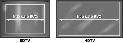
Figure 11-17 Title safe for SDTV and HDTV
Title safe for SDTV is the center 80% of the video frame. Make a rectangle the size of the video frame and scale it by 0.8 and that will make a title safe guide. The reason it is so much smaller than HDTV’s 95% is historical. In the early days of TV the displayed picture size varied quite a bit from television set to television set. To make sure the titles would show up on the worst-case television set it was necessary to make sure they were within the 80% rectangle. Today TVs are much more uniform but the practice endures anyway. HDTV does not suffer from this kind of set-to-set variation, so the title safe rectangle is a snug 95%.
11.4 3:2 PULL-DOWN
The telecine process transfers film to video but there is a fundamental conflict between their frame rates. Film runs at 24 fps and video at 30 fps. We need to end up with one second of film becoming one second of video, so the solution is to stretch 24 frames of film out to 30 frames of video using a technique called 3:2 pull-down. In order to change 24 fps to 30 fps, every 4 frames of film has to be mapped to 5 frames of video. This is done by spreading every 4 frames of film out to 10 video fields. Some think of this as expanding the film, or cine, to match the video, so they call it cine-expand.
Figure 11-18 shows how 4 frames of film are mapped into 10 video fields. These 10 fields form a 5-frame sequence of video that is repeated for the length of the clip. (To view a high resolution version see www.compositingVFX.com/CH11/Figure 11-18.tif) The first frame of film (frame “A”) is mapped to the first 2 video fields as one might expect. Film frame B is then mapped to the next 3 video fields, frame C to 2 fields, and frame D to 3 fields. The entire film clip is transferred to video fields using the pattern or “cadence” of 2:3:2:3:2:3:2:3…, etc. One side effect of this is that the number of frames will increase by 25%—96 frames of film become 120 frames of video.
One problem that this creates for the compositing community is that the 3:2 pull-down periodically creates video frames that are an interlaced mix of two different film frames. We saw in the “Coping with Interlaced Video” section on p. 200 that this is bad. Check out video frames 3 and 4 in Figure 11-18. Frame 3 is a mix of film frames B and C, while frame 4 mixes frames C and D. As a result, two out of every five video frames have two different “moments in time” like the nasty interlaced video we saw above. These mixed frames must be eliminated before we can do any serious manipulation of the images.
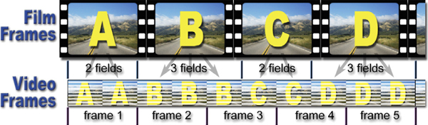
Figure 11-18 The 3:2 pull-down pattern
You may have noticed that the first video frame made with the “A” frame of film went down with 2 video fields with the next film frame getting 3 fields. So why is it called a 3:2 pull-down instead of a 2:3 pull-down? Because, years ago, when telecine was young, the cadence really was 3:2:3:2. Later, for technical reasons, it was switched to 2:3:2:3, but the old “3:2” name has stuck for the sake of tradition. Plus it was too hard to retrain everybody.
The 3:2 pull-down is used in far more places than just transferring film to video. When 24 p video has to be broadcast, the broadcast standard is 30 fps interlaced, so the 24 p video is transferred to 30 fps interlaced videotape using a 3:2 pull-down. Another application of the 3:2 pull-down is the DVD player in your home. When a feature film is mastered to a DVD it is done at 24 fps, then the DVD player detects this and applies a 3:2 pull-down on the fly in order to send a 30 fps signal to the TV set. The reason this is done is to save the disk space that would have been wasted on the 25% duplicated fields and instead that disk space is used to improve the quality of the picture coming off the DVD. (To see a movie showing the 3:2 pull-down pattern download www.compositingVFX.com/CH11/3-2 pulldown.mov and single step through it.)
11.5 3:2 PULL-UP
Any 30 fps video that has a 3:2 pull-down in it can be restored back to 24 fps using a process called 3:2 pull-up. The 3:2 pull-up process simply drops out the third video field in the 2:3:2:3 pattern restoring it to a sensible 2:2:2:2 pattern like the example in Figure 11-19. (To view a high resolution version see www.compositingVFX.com/CH11/Figure 11-19.tif) It shows the third video field for frame B and frame D being dropped out generating a new set of 4 frames made up of exactly 2 fields each. This creates a set of video frames that exactly matches the original film frames.
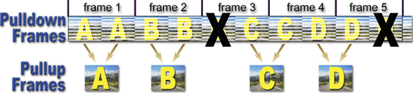
Figure 11-19 The 3:2 pull-up pattern
The 3:2 pull-up is non-destructive because it is simply throwing out duplicate fields. The number of frames drops by 20%, but one second of interlaced video is now one second of 24 p video. Since the 3:2 pull-up reverses the telecine process some refer to this as “reverse telecine.” Others see it as compressing the 30 fps video back to 24 fps so they call it “cine-compress.” We just call it a pain in the arse.
There is a nettlesome detail to performing a 3:2 pull-up, and that is trying to figure out the “cadence” of the original 3:2 pull-down pattern. Referring again to Figure 11-19, if you count the video fields starting at the left you will see that field number 5 is dropped out, then field number 10. You might conclude from this that a 3:2 pull-up drops field 5, then every fifth field after that, but then you would be wrong 80% of the time. It drops field 5 of the pull-down if and only if the clip starts on an “A” frame. If that frame were cut out in editing, which happens about 80% of the time, it would make the “B” frame (frame 2) the first frame of the clip. In this case you would drop the third field, then every fifth field after that. And so it goes down the line with the 2:3 cadence being any one of five possibilities depending on which of the five video frames is the first frame of the clip.
How are you supposed to cope with this? Your software should offer you five possible cadences to choose from to match whichever of the five possible frames your clip starts on. You might have to try each of them to discover the cadence of your video clip. The test to ensure you have found the right cadence is to check at least five sequential frames to make sure all of the interlaced frames are gone.
11.6 DV COMPRESSION ARTIFACTS
There has been a recent explosion in the use of a new generation of video cameras known as DV cameras—“DV” for Digital Video. They go by the names of DV, DVCAM, DVCPRO, and others, and are starting to show up in visual effects productions for both SDTV and HDTV. The attraction for videographers is that these cameras are much cheaper than the previous generation and they record on inexpensive 1/4-inch cassette tapes. Their crimes against pixels are that they not only use a sparse 4:1:1 sampling scheme but they compound this by adding a 5 to 1 JPEG data compression that further corrodes the picture information. They also only capture a 720 × 480 picture to save even more money. While the video they capture might look OK to the eye, you can’t fool the computer.
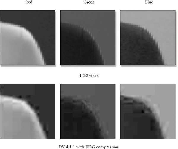
Figure 11-20 Comparison of 4:2:2 video with DV video
Figure 11-20 illustrates the sorry difference between 4:2:2 sampled video (top row) and the DV sampling of 4:1:1 with JPEG compression (bottom row). It compares the red, green, and blue channels so you can see the hideous artifacts introduced by the low color sampling combined with data compression. The problem with this is that when watching the video on a TV monitor it looks surprisingly good. This misleads inexperienced people to believe that it will be fine for bluescreen and greenscreen shots. It will not. You will spend more time trying to cope with the 4:1:1 sampling and compression artifacts than pulling the matte. The bottom line is that trying to key DV video will result in a lot of extra work and poor-quality results. You should warn the client. (To view a high resolution version of compression artifacts in the blue channel see www.compositingVFX.com/CH11/compression artifacts.tif)