
Chapter eleven
The slit approach, typically for vigorous winter games such as rugby and soccer
Winter use of natural turf for sports requires the surface to remain tractively efficient throughout the time of year when, in Britain, weather conditions are far from favourable. Because temperatures are low the grass growth is minimal, and because rainfall much exceeds evaporation the shear strength of the turf is threatened by physical damage to the grass and excessive wetness in the soil. To withstand the severe wear that vigorous play with studded footwear can cause, the sward must enter the playing season thick at the base and deeply rooted. Damage to the grass will tend to accumulate until repair by re-growth becomes possible the following spring. When conditions are not ideal therefore, the need for damage limitation may require discretion in use. Of the things we can do to help, efficient soil drainage should be regarded as the top priority.
11.1
Sand/gravel slits under coarse turf
11.1.1 Function
A slit system is merely the sports-field equivalent of the mole-assisted pipe system used in agriculture (Chapter 2, page 28). However, in sports turf, because we are working with a permanent sward not subject to periodic ploughing and re-seeding, the mole drainage approach can be made more efficient by concentrating and stabilizing the vertical slit with permeable fill—top half sand, bottom half gravel.
As the first task of a sand/gravel slit system is to intercept excess rainfall that would otherwise pond on the surface, the permeable fill must be brought right through to the surface. To maintain the infiltration routes clear, the top must be kept sandy, either by regular
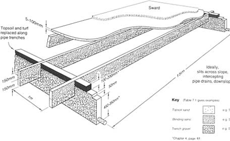
FIGURE 11.1 Diagram of a standard slit system. Note that 15 cm of trench gravel in the base of slits allows 15 m spacing between pipe underdrains (Chapter 7, page 114).
topdressing, never more than the existing sward can rapidly grow through, or by covering with a deep sand carpet on which the sward has to be established anew.
In a slit system the function of the pipe underdrains is to intercept and discharge the water brought to them by the slits. The pipes, therefore, can be allowed to run in parallel succession down slope. The slits are required to intercept water flowing over the surface or through the topsoil and, therefore, should run generally across slope. To limit the distance they have to convey water to a drain, they should run across the pipe system more or less at right angles, Figures 11.1 and 11.2.
11.1.2
Pipe depth and pipe trench backfill
Assuming no subsoil impediment to trenching, pipe depth need only be what is required to provide adequate protection for the pipe from the trenching operations involved in the installation of slits.
The backfill for perforated plastic pipes need be no larger than can be accommodated within the Stewart zone trench gravel and should extend upwards from the pipe to link cleanly through to the trench gravel in the slits, i.e. 50–75 mm (2–3 in) above the proposed depth of the sand/gravel slits. The surface of the gravel in the pipe trench should then be screened by a 25 mm (1 in) covering of blinding sand and the remaining depth made good with topsoil and turf.
Should, for some reason, extra pipe runs be added after slits have been installed, it would be as well to raise the top of the trench gravel in the pipe trench to coincide with the top of the trench gravel in the slit. This will ensure that water discharging laterally through the slit
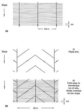
FIGURE 11.2 Layouts for slits and pipes: (a) ideal; (b) adapting to an existing, herringbone, pipe system.
will be in no way impeded as it enters the region over the pipe trench.
11.1.3
Slitting over existing pipe system
A herringbone pattern of pipe underdrainage is impossible to upgrade efficiently by super-imposing simple systems of mole drains or sand/gravel slits Either the slits have to change direction every time they cross a main or, when running all in one direction, they will vary in efficiency because of the varying lengths over which they accumulate water (Figure 3.1(a)). It is now generally accepted that supplementary provision for surface interception is essential on loam and clay soils used at all intensively for winter games. In these circumstances therefore, a herringbone system of underdrainage is unhelpful when compared with a grid system in which the laterals run all in one direction to mains (Figure 11.2(a)). As Figure 11.2(b) indicates, upgrading a pitch with slits over a herringbone system of underdrains may well require the prior installation of yet more pipes.
11.1.4
Sand-capping the surface
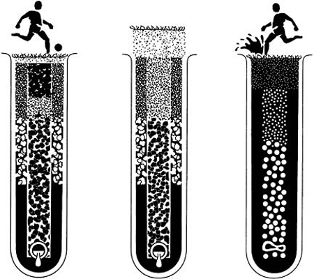
Anyone installing slits should be forewarned of the need to take measures to counteract the inevitable tendency for soil to cap over the surface. Sand and gravel in slits will respond differently to repeated cycles of wetting and drying compared with the adjacent soil. The end result is that the level of the sand and gravel in the slits progressively sinks relative to the soil and, if the sand level is not maintained by topdressing, the soil will eventually seal over the surface (see the sequence in Figure 6.1). It is essential, therefore, that a slit-drained surface be protected from the start by an adequate, overall capping of sand. This may involve either a substantial topdressing repeated annually, or a deep carpet of 75–125 mm (3–5 in) depth on which a new sward will have to be established. Alternatively, provision will have to be made for some form of regular, repeat micro-slitting, as described in Chapter 2, page 43.
11.1.5
Upgrading the original soil surface before carpeting with sand
A sand-carpeted, slit-drained pitch will generally stand up well to intensive use, both in wet and dry conditions, but there have been instances where the quality of the sward has deteriorated, particularly in response to drought. This may arise where there is a lack of sufficient root penetration into the soil beneath the sand carpet.
Such a problem can originate in the sand having been laid directly over a made-up or degraded soil surface; for example, a soil without a satisfactory initial structure or an earthworm population capable of developing the structure that is so essential for a healthy rooting environment. As a result, the effective rooting medium is no more than the sand carpet itself, which may soon become exhausted of its initial organic and chemical supplements and will be very limited in its water reserve. Though the original soil surface in a sand carpet construction is to be buried out of sight, its quality should not be ignored. The long-term viability of the system depends on its biological vigour.
Therefore, before capping the surface with sand, consider what long-term advantages are to be gained from either of the following soil treatments carried out prior to slitting:
1. mechanical action to relieve soil compaction;
2. incorporation of lime and phosphate to counteract any acidity unfavourable to earthworms and encourage invading roots to proliferate by branching;
3. delay for a year before proceeding to slitting so as to superimpose a minimum of 100 mm (4 in) of fresh, good quality topsoil, after the installation of the pipe drains. This would also entail raising the level of the top boundary of the gravel in the pipe trenches by an extra 100 mm (4 in), and establishing a temporary sward to re-stabilize the surface before starting the slitting operation.
11.1.6
Grassing up
The working-up period after seeding a new construction can be difficult. The contractor may be given the responsibility for the establishment of the sward but will be unhappy about keeping men hanging about to ensure that all the necessary small operations are carried out at the right time for maximum benefit. The local authority maintenance team will already have a full schedule of routine work and may be disinclined to take on an additional commitment amounting to the medical equivalent of a period of intensive care.
In dry weather the establishment of a grass sward from seed on a sand surface is virtually impossible. The problem is to keep the seed in contact with moisture long enough to effect germination and then sustain the seedling until its roots have extended into a soil moisture reservoir. This is likely to be particularly difficult along a slit as there is nothing immediately beneath the surface but sand and gravel. The adjacent soil, though potentially a moisture reservoir, may intensify the desiccation threat initially by abstracting stored water from the sand.
To assist sward establishment the main aim should be to catch a period at the end of the growing season when the soil is moist but still warm (section G.2 and Figure G.l). Then, as a further precaution against surface desiccation, cover the seed with a mulch of grass clippings. Keep irrigation in reserve to sustain growth should the weather turn dry enough to threaten seedling establishment after germination has been achieved. No play should be contemplated until the whole surface has been stabilized by a well-rooted sward. Once rooted into the adjacent soil the grass along the slit will be remarkably persistent.
The sand-carpet-over-soil situation is likely to be less of a problem provided the seed is well incorporated to a depth of the order of 10 mm. Thus buried, the seed will be protected against all but the extremes of desiccation and, with only loose sand to displace, there is no risk of a cap impeding shoot emergence. Even if the sand carpet eventually dries out it will still act as a dry mulch to conserve water in the soil beneath. A major aim during the period of sward establishment should be to coax the roots through the moisture and nutrient reserves in the buried soil layer, then keeping them there by avoiding the surface accumulation of organic debris and phosphate.
On any sand surface wait patiently for complete grass cover before allowing use.
11.1.7
Special maintenance required to sustain the efficiency of sand-capped and sand-carpeted slit surfaces
General advice on maintenance is given in section 11.4.
With a slit system of drainage brought through to the playing surface there is an inevitable need to topdress the surface with sand annually. A substantial quantity of fine sand will be required to make good the settlement along the line of the slits and maintain the freely permeable link right through to the surface.
For the sake of the quality of the soil between slits, earthworm activity should be encouraged by adding lime to maintain the pH above 6.
With inappropriate maintenance a sand-carpeted, slit pitch, devoid of worms, will first become green and mossy and then capped by an organic, phosphate-rich thatch encouraging surface rooting and sensitivity to wear. Alternatively, with earthworms present to continually incorporate and recycle organic debris, there is then the problem of fine soil brought up in casts gradually transforming the texture of the original sand surface. Although one or the other of these adverse trends must be anticipated right from the start, in either event the remedy is the same. An annual sand topdressing will be required either to dilute and bury organic and fertilizer residues or dilute the fine particle content of earthworm casts.
11.2
Possibilities for the use of mini-slits under fine turf
Mini-slits are generally 15–30 mm (3/8-l1/4 in) wide, 200–300 mm (8–12 in) deep, and spaced 200–300 mm (8–12 in) apart. They are so thin they can be inserted by trenchless methods, without excavation, and without undue damage to the surface (Chapter 2, page 42).
The slit drainage approach to efficient drainage was developed originally to meet the needs of coarse turf used for vigorous winter games (e.g. as illustrated in Figures 11.1 and 11.3). If miniaturized, however, it is possible to conceive of this same general approach to drainage being used under the fine turf of bowling and golf greens, tennis courts and croquet lawns, cricket outfields and hockey pitches. To achieve this three potential problems have to be overcome.
1. Different growing conditions are offered to grass rooting into the sand of a slit, or a pipe trench, compared with grass rooting through any general sand cap to the underlying topsoil.
2. Differential settlement of the surface is caused by the dissimilar swelling and shrinking of the sand in a slit compared with the adjacent soil.
3. For golf and crown bowling greens, there is the need to adapt the normal, rectilinear grid layout of pipes and slits to cope with surfaces that slope irregularly.
On the plus side, if the grass roots through the surface capping of ameliorated sand to exploit water stored in the underlying soil, this type of construction is less vulnerable to drought than a construction rafted over a drained gravel bed. Thus, elaborate provision for irrigation is less essential but, at the same time, a generally drier soil-moisture regime can be maintained which is more favourable to fescue and less favourable to annual meadow-grass.
However, even if a drainage rate similar to that of a standard slit system is achieved—2 mm/h (2 in/day)—this is only a tenth of that which might be expected when rapid infiltration is possible over the entire surface of an all-sand topsoil, rafted over a drained gravel
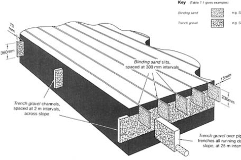
FIGURE 11.3 Drainage scheme for football pitch with pipes, channels and slits, installed by trenchless methods. Delay slitting until surface is cultivated, de-stoned, re-levelled and stabilized by grassing over. After slitting, topdress standard sized pitch with 25–50 tonne of topsoil sand. Repeat annually thereafter.
bed. Thus, to cope with periods of intense rain, thought will have to be given to assisting runoff by suitably sloping the surface.
Slits are normally aligned across slope to maximize their efficiency for the interception of water moving over and through the topsoil. By contrast, the pipe underdrains, which are there to intercept and clear water from the slits, should, ideally, run down slope. This leads to a simple, rectilinear layout when the surface slopes uniformly in one direction. However, to adapt such a system to the gentle but irregular sloping surface of a golf green, the slits will all have to tend to follow the contour lines and may not be evenly spaced. Similarly, the underdrainage will have to follow any well-defined roughs that slope steadily in the general direction required, crossing the slits at right angles.
11.2.1
Mini-slit drainage on a plane surface
Because mini-slits are thin and filled with one material, typically blinding sand, their limited capacity requires their relief into a linked system of underdrains at relatively short intervals. If this is all to be done by trenchless methods, using the three-tier design illustrated in Figure 11.3, it is best accomplished in two stages. First, the pipe trenches and gravel channels should be installed on an exposed, sub-surface layer where any heave can be levelled out prior to the topsoil being superimposed, and without undue concern for capping. Then, after the carpet of topsoil has been superimposed and stabilized by grassing over, a direct link between the surface and the underdrains can be established by installation of the mini-slits. Alternatively, the gravel channels can be piped to extend their length of run so as to complete the scheme in just two tiers of artificial drainage.
Obviously, regular sand topdressing or repeat mini-slitting will have to be a feature of maintenance if the thin slit system is to remain linked directly through to the surface.
11.2.2
Possibilities for mini-slit and other forms of drainage on an irregularly sloping surface
On a smooth surface, runoff will clear all excess water from the steeper slopes but will add to the excess water accumulating on the longer, gentler slopes, and in the receiving hollows. The only practical alternatives available to cope with this situation are either to eliminate the hollows or introduce underdrainage beneath the hollows, linking this with the surface through topsoil organized to provide for the necessary infiltration.
The simplest and probably the cheapest approach is to mould the required surface from the existing topsoil, grading throughout so as to avoid internal hollows and shed all surface water to soakaways beyond the perimeter. Gradients, not less than 1:60 nor more than 1:20, will probably suffice to provide for continuous flow within an overall configuration acceptable for play.
If an unwanted, enclosed hollow develops on a made-up surface, as a result of differential settlement, then either the hollow should be filled in or provided with effective underdrainage.
To eliminate an enclosed hollow by infilling, fold back the turf and build up with more soil similar to the existing, grading as required to maintain surface flow across the new surface. A depression that is merely infilled with sand will leave the water-holding surface intact and the sand will do no more than mask the presence of the water held above the buried soil layer. Only when a uniformly textured, continuously shedding surface has been established should topdressing with sand be contemplated.
If an underdrain is to be inserted through a fine-turf surface the job will have to be done very neatly. Using boards to work off, first remove cleanly cut turves along the line of the pipe trench and store carefully for subsequent replacement. Excavate through the exposed soil a narrow trench no more than 50–75 mm (2–3 in) wide, i.e. the minimum necessary to allow for the insertion of the pipe. The object being to intercept surface water and discharge it directly into the pipe, the trench need be no deeper than is required to provide for any necessary grading to the outfall and to keep the pipe clear of all spiking operations; 300–450 mm (12–18 in) would normally be adequate. Backfill over the pipe with trench gravel to 150 mm (6 in) from the new surface, then blind with 50 mm (2 in) of blinding sand and continue through to the new surface on which the turf is to be replaced, using topsoil sand ameliorated with 2% seaweed meal, and 2% horticultural lignite or equivalent. Topdress with a phosphate-rich fertilizer, saturate and then neatly replace the turf.
If the original soil is not particularly sandy, then replace the topsoil sand at the top of the pipe trench with some of the original, excavated topsoil. Thin, sand-filled mini- or micro-slits can then be inserted across the trench to effect surface interception and link below into the layer of blinding sand in the pipe trench. Slicing open thin slits with a spade may well be all that is necessary but may have to be repeated periodically.
As with all made-up soils, the backfill in the pipe trench should be consolidated into place to reduce the extent of any subsequent, long-term settlement. This process should be repeated as each layer is put into place. Any residual settlement will have to be taken out by careful luting along the line of the trenches whenever a topdressing of sand is applied subsequently.
The pipe trenches—often only one—should run through the base of the receiving hollows, aligned with slope. Any extension of the system will normally require only gravel-filled channels or slits. The channels can be used to extend the underdrainage into subsidiary, receiving hollows, the backfill matched to that in the pipe trench with which it is linked.
Slits to improve surface interception on the gentler slopes where runoff is sluggish should be aligned across slope, traversing around the contour. Should there be any problem about defining a contour it might not be inappropriate to apply the simple technique traditionally used in India for laying out irrigation channels. This makes use of a man-sized A-frame with plumb bob suspended from the apex to swing free just below the level of the crossbar. The two feet of the frame will be at the same level when the plumb line intersects the crossbar at the mid point. Steady progress around a contour can then be achieved by rotating the frame in half circles, one leg, the trailing leg, lifted clear of the ground at each turn. Pegs should be inserted to define the line as you go.
Because a uniform, smooth surface is essential for golf and bowls, the pipe-trenched and sand-slit surface should be masked by a uniform carpet of sand. The depth of the sand carpet must allow for effective infiltration and lateral discharge to the underdrainage system. With underdrainage interception at 1–2-m (1–2-yard) intervals a 100-mm (4-in) depth of a topsoil sand carpet will generally be adequate except, perhaps, in the receiving hollows. Above the sand carpet, however, a turfed surface layer will develop which, if fine sand, loamy sand or organic matter dominated, could become persistently wet, especially if perched over a coarser, e.g. medium-textured, sand carpet. It is important, therefore, that the surface should be managed so as to maintain the whole turf layer similar to, or coarser than, the texture of the underlying sand carpet. Alternatively the sand carpet should be kept permanently linked through to the surface by hollow-tine core holes filled with sand of texture similar to, or coarser than, that of the sand carpet to which it is linked.
Clearance of water through the sand carpet will depend on the nature of the underlying soil and the combined effect of sand depth and slope on the ability of the sand to pull water down from the surface. There will be a tendency for the high spots to dry off excessively but this can be counteracted by differential maintenance, e.g. less intensively hollow tining the high spots, or core filling with a finer textured sand. In low-lying areas the sand depth, from the top of the sand carpet to the top of the gravel layer in the underdrainage trenches, should exceed the critical tension of the carpet sand (Figure 4.3 (b)).
Do not ameliorate the sand carpet with either soil or peat as this will encourage water retention and risk souring the root zone by promoting anaerobic decay.
11.3
Upgrading an existing pitch for improved performance in winter
11.3.1
Initial state
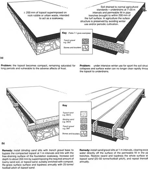
Figure 11.4(a) illustrates two traditional constructions where surface drainage will almost inevitably break down under the strain of intensive winter use. Figure 11.4(b) illustrates how each may be improved. In one case a rubble foundation was intended to provide for all the necessary drainage; in the other, an agricultural pipe system. In effect, both have been provided with a potentially efficient underdrainage system but neither anticipates any problem in getting excess surface water through a topsoil destructured by treading. Both cases require provision to allow for adequate surface infiltration and the direct channelling of any excess into the underdrainage provided.
Where a pipe system of underdrainage already exists it may well be intact but show little sign of use. Whether or not all or just parts of such a pipe system can be integrated into the upgrading plan will depend on:
- the condition of the original pipes;
- the extent to which the laterals are all aligned in one direction;
- the nature of the pipe-trench backfill and its proximity to the surface.
Pipe interval is seldom a problem—the discharge potential of the pipe system usually being more than adequate.
11.3.2
Example of an advisory report on two slit systems
Pitch A is a slit system with progressive accumulation of a sand-capped surface, whereas pitch B is a slit scheme immediately covered with a thick, ameliorated, sand carpet.
Having seen the soils on pitches A and B there is no doubt that both require a scheme of sand/gravel slits to efficiently infilter surface water through to an upgraded system of pipe underdrains. Under both pitches there is an intact pipe system of underdrains, but neither is organized to intercept through to the surface. From the dry, clean state of the chambers it seems unlikely that they have ever been called upon to carry very much water.
In A, because there is no stone restriction to deep trenching and the depth of the topsoil is satisfactory, a normal slit system can be introduced without difficulty, and sand topdressing restricted merely to that required annually to protect the slit surfaces from becoming capped by soil. In B, however, a relatively deep surface carpet of sand is required, not only to protect the slits from soil capping but, as we shall see, to deepen the topsoil.
Sands and gravels are defined according to the Stewart zone system (Chapter 7, page 114).
Preliminaries
1. The sward on both pitches is very weedy. An effort should be made to get on top of this problem as soon as possible by using an appropriate weedkiller. Consideration should then be given to controlling the growth of the existing swards by mowing. To avoid rank growth during the reconstruction operations, do not apply fertilizer.
2. At A the surface is very uneven and requires re-truing. This should be achieved by minimum disturbance, importing good topsoil of similar texture to the existing to fill in the depressions. Consolidate any introduced soil, supplementing further if necessary to achieve true level, then re-loosen the surface to seed.
3. At B there is a need to increase the depth of the topsoil. At present it is only of the order of 100–125 mm (4–5 in) and lies directly over a compact subsoil with tip rubble beginning at 400 mm (16 in). This extra depth of topsoil can be an ameliorated sand carpet introduced after the pipe drains and slits have been installed.
Pipe drainage
1. In general, on both pitches, pipe provision should aim to support an overall design rate of 50 mm (2 in) per day. Choice of pipe will depend on area served, gradient and function (Table 2.1).
2. The pipe laterals that intercept the slits should run in parallel succession at 15-m (17-yard) intervals, directly downhill, linking into the existing catchment drains that run along the down-slope margins. The links should be achieved by purpose-made junctions causing no interruption to flow.
3. The pipe laterals at A should be installed at a depth of 600 mm (24 in), below the depth of the existing herringbone system. All severed, old pipes to be positively linked into the new system from the uphill side. Downhill the old pipes should be closed off by an appropriate cap.
4. At B place laterals at the shallow depth of 450 mm (18 in). This will avoid most of the major obstacles in the rubble substratum.
5. The new laterals should be backfilled with trench gravel to within 150 mm (6 in) of the existing surface and, thereafter, 50 mm (2 in) of blinding sand, followed by replacement of the original turf, bedded in topsoil.
5. Examine all links into chambers and correct any adverse consequences of scour and differential settlement in the pipe trench adjacent to the chamber.
Aim to complete 1–6 by the end of autumn. Assuming the re-turfed and seeded areas take successfully it may be possible for both pitches to be used with discretion over winter.
Slits and surface
1. Work to install slits in both pitches should begin as early as possible in the following spring.
2. The slits should be 50 mm (2 in) wide, 150 mm (12 in) deep, and should run in parallel succession at 1-m (1-yard) intervals, across slope, i.e. at right-angles to the lateral pipe system. Backfill should consist of a lower, 150 mm (6-in) layer of trench gravel, and an upper, 150-mm (6-in) layer of blinding sand, the sand layer being brought right throught to the surface.
3. At A, the slits should be over-topped to a height of 25 mm (1 in) with topsoil sand, ameliorated with 2% seaweed meal and 2% horticultural lignite (or an equivalent organic compost). Topdress overall with pre-seeding fertilizer and then overseed with a dwarf ryegrass/fescue-dominated seeds mixture, aiming to place the seed within the immediate surface of the sand. Make a second seeding pass along the line of each slit and then, rolling parallel to the slits, firm the sand around the buried seed.
4. At B, spread 100 kg/ha of urea and 300 kg/ ha of ground rock phosphate (or similar). Spread 480 t (dry weight) of topsoil sand per hectare, plus 301 of horticultural lignite and 30 t of seaweed meal (or equivalent organic compost). Then cover with another 1120 t/ha (dry weight) of topsoil sand.
Using a spring-tine harrow (or similar), set to skim over the top of the original, buried soil, work the organic material up towards the surface. Two slow passes at right angles should be adequate. The aim is to mix but not bring very much of the buried organic matter right through to the surface. Roll and re-level repeatedly, using machinery that will avoid rutting. Use a 3 m (9–12 ft wide) bar-grader to achieve the final, consolidated, true surface. Protect against windblow by watering if necessary. Topdress with pre-seeding fertilizer and seed with a dwarf ryegrass/fescue-dominated seeds mixture. Insert seed by means that will work most of the seed some 10 mm (1/4-1/2 in) under the surface. Roll to consolidate sand around the buried seed.
5. After seed germination, maintain both pitches as prescribed in the attached maintenance schedule (section 11.4).
6. Slitting and surface renewal may be achieved by the autumn, but ideally no play should be allowed on either pitch until the following year. Growing season conditions will be required to develop a vigorous, thick sward and, in the case of pitch A, to apply protective topdressings of topsoil sand. These sand topdressings may well have to be concentrated first in the vicinity of the slits so as to counteract any tendency for the surface in this area to slump. And note, even on pitch B, where a deep, sand carpet will have been introduced, there will still also be a need for annual topdressings of sand to counteract any tendency to develop an organic or fine-soil cap (section 6.3.1).
11.4
General guidance on coarse turf maintenance where, on balance,earthworm activity is considered to be potentially beneficial
Greater discretion in use and an improved programme of maintenance may alone achieve all the improvement that a beleaguered groundsman may require but, frequently, some inherent limitation of the site has to be overcome before even good maintenance can hope to be effective.
Before proceeding with any expensive construction or re-construction programme it is important to realize the nature of the maintenance that will be necessary if all the potential benefits from the construction work are to be realized. Nothing created in sports turf will remain for long as constructed unless maintained in a manner sensitive to the inevitable trends towards change that have to be continually controlled.
Much of the advice given under the heading of maintenance for fine turf (section 10.5) applies equally to a worm-worked sward. The features listed below simply draw attention to those which are of special significance for winter games pitches where stud wear is an inevitable hazard and, on balance, the effects of earthworm activity are considered to be beneficial.
11.4.1
Liming, fertilizing, weed-killing and over-seeding
1. Maintain soil pH above 5.5 by application of ground limestone. Where necessary, treat initially by means of a single application at the rate of 5 tonne/hectare (2 tons/acre). Spread evenly in calm, dry weather, at any time of the year. Check pH again after 2 years and thereafter every 4 years. Monitor pH only within the top 75 mm (3 in) of the soil.
2. In mid-April, or when soil temperature at 250 mm (10 in) has reached 10°C and there is ample evidence of renewed growth, consider if the sward needs weed killing as well as fertilizing. Remedy as necessary and apply the first of three fairly light, spring and summer dressings of a fine-particle fertilizer, supplying mainly (or solely) nitrogen and potassium. Repeat mid-June and mid-August. Do not apply in drought but when rain is expected within 24–48 hours. Eliminate one dressing if drought persists.
Each second year, apply a standard high-phosphate, low-nitrogen autumn dressing (mid-September), on a thoroughly spiked or slit surface. To boost growth along sand- and gravel-filled drain trenches, consider applying nitrogen and potassium as a liquid feed at low concentration along the trench runs, using a sprayer or watering can. Treat during the growing season whenever the yellowing symptoms of nitrogen deficiency show up.
3. Do not leave bare patches to seed themselves or nature may insert a broad-leaved weed, an unsuitable grass, or moss. Immediately heel back all displaced turf after play and consider the need for selective over-seeding both in spring and autumn. Though early autumn is usually the best time to seed, over-seeding may well be necessary in spring to treat damage caused by winter use. If a machine that places seed directly into the surface of the soil is not available, prepare the surface by raking or close, shallow spiking. On sandy surfaces, roll after seeding to improve seed contact with the soil.
11.4.2
Mowing, brushing and sand topdressing
1. During the growing season use a sharp mower to cut at 50 mm (2 in) for rugby or 30 mm (11/4 in) for soccer, whenever the general growth height reaches 75 mm (3 in) and 50 mm (2 in) respectively. When the grass is growing well this will mean cutting once a week for rugby and once every 4–5 days for soccer. Remove clippings if earthworms are not active or if the grass is at risk of being smothered by clippings lying in swathes. To cut effectively at a height of 20–50 mm (1–2 in) a mower requires to be sharp. This means regular servicing, at the very least once a year in late autumn, after all topdressing and mowing has virtually ceased for the season.
2. Though worm activity can greatly benefit grass growth their casts will smear and give an unsightly appearance if the grass is cut too low. They can also be sites for weed invasion. For both these reasons it is desirable periodically to disperse the casts by brushing. A good rotary brush or a heavy drag brush can be effective for this purpose ii the casts are fairly dry and crumbly at the time. Brushing is most likely to be required in spring and autumn when earthworm activity peaks. Brushing will also assist in grooming the sward, bringing sprawling shoots up to the mower for cutting.
3. Sand topdressing is essential to maintain the efficiency of modern sports-turf constructions where drainage depends on the maintenance of free-draining pathways, continuous from the surface right through to the pipe underdrains. In effect this means maintaining a sand surface overall, or at least along the surface of the installed drainage slits. Slits can be progressively down-graded by soil contamination resulting from foot traffic and earthworm activity. To counteract this, a uniform topdressing of the order of at least 40 tonne/hectare (16–17 tons/acre) of topsoil sand should be applied each summer during dry sunny weather. Spread the sand out in an evenly spaced arrangement of piles or wind-rows, until powder dry, then according as the priority is to true or merely topdress, lute or drag brush into the base of the sward.
11.5
A cautionary tale illustrating what can go wrong during and soon after construction
11.5.1
The initial concept
This is a story of unscientific design, inefficient workmanship, inadequate supervision and inappropriate maintenance. It concerns a scheme of drainage for a new 14-hectare (35acre) sports ground, 700 m (765 yards) long, across slope, and 200 m (218 yards) wide, down slope. The final surface sloped uniformly at a gradient of 1:100 and was made up of material similar to subsoil.
Apart from two pitch areas set aside for hard porous and sand carpet constructions, the whole of the playing field was underdrained by pipes laid out in a herringbone pattern. Mains were all directed down slope, laterals coming off alternately right and left, orientated diagonally across slope. As Figure 3.1(a) indicates, if such a system does not suffice on its own the orientation of the laterals makes it difficult to up-grade efficiently without adding more pipes. This is not to make good any shortfall in number but to compensate for a layout that unnecessarily complicates the introduction of an efficient system of sand/gravel slits.
One of the two special areas was underdrained by mains and laterals laid out in a grid system, then sand/gravel slit and deeply sand carpeted. Initially, it was the only grass surface on which it was possible to achieve a sustained programme of winter use. The other special area was laid out as a hard porous construction like that discussed in Chapter 13.
11.5.2
Ensuing problems
All available funds having been spent on the initial construction, the groundsman was then left to carry on as best he could with two potentially useful pitches and the rest of the area rapidly falling out of use because the herringbone underdrainage was unable on its own to prevent winter use churning the surface to mud. However, when the groundsman began to investigate his problems, he started by looking at several persistent wet areas over drain runs. This revealed that he not only had problems of design but also inefficient installation. It was at this stage that outside advice was sought.
Field evidence and the lessons to be learnt
1. Many wet areas were associated with pipes crushed flat. In one instance this damage extended for a distance of 6 m (20 ft), presumably the result of heavy wheel pressure transmitted directly onto the pipes through the loose gravel backfill. Elsewhere, gaps were found at the junctions between laterals and mains, and wide gaps, up to 1 m in length, were found at junctions along mains. One pipe was found broken where it had been laid across a sharp piece of buried metal. Twelve such faults were found on one pitch alone.
How did all this come about? Where was the clerk of works at the time of installation? What of the principle of inspection before cover? What should be our attitude now to weekend work, popular with contractors working away from home but unlikely to be capable of close supervision? How could such faults arise? Could some methods of installation involve an unsuspected measure of drag, when the pipe is covered immediately by backfill? Should we require a simple locking system at junctions?
2. On the sand-carpeted pitch the underdrainage consisted of a parallel succession of pipes running downhill at 15-m (16-yard) intervals and 500–600-mm (20–24-in) depth, plus gravel-filled trenches, running across slope at 2-m (2-yard) intervals and 350–400 mm (14–16 in) in depth. Here, seven instances were found of crushed or broken pipe where the gravel-filled trenches crossed the pipe system.
Could this evidence be indicating an effect of downward pressure from trencher tines transmitted through loose gravel? Or could it be an effect of one person's eccentric method of backfilling and consolidating gravel within narrow trenches? The fully integrated methods now used for cutting trenches, laying pipes, placing and consolidating fill, all in just one or two passes of heavy machinery, may be quick and superficially tidy but who has checked to see the consequences below ground?
3. When a new contractor was called in to achieve a complete reconstruction, a new drainage system was superimposed with pipes running downslope 450 mm (18 in) deep, about the same depth as the suspect pipes in the original herringbone system. However, to avoid risk to the new pipes during subsequent slit trenching, the decision was made to first install gravel filled, slit trenches at fairly close intervals, across the slope, and then intercept these with the new pipe drains running down-slope. Finally, close-spaced, sand mini-slits were injected downslope to direct surface flow to the gravel slits and thence to the new system of pipe underdrains.
Great difficulty was experienced from the start because the trenchable topsoil that should have been installed to a placement depth of 30 mm (12 in) was found to be less than 150 mm (6 in) deep, and there it rested directly on a consolidated, stony subsoil of tipped rubble. The slit trenches were bound to be difficult to excavate to any depth and, since they were dug before the installation of the new pipe system,progress was further hampered during bad weather by the progressive accumulation of water within the working area.
In this case the slits were installed in succession from the bottom to the top of the slope. Had this been done in reverse, i.e. top to bottom, the first slits installed might have helped to maintain the downslope area free of surface runoff, allowing progress to be maintained through a period of unsettled weather. Subsequent installation of the new pipe system by trenchless methods was also very difficult because the soil was still wet and this increased the risk of further damage to the original herringbone pipe system. Timing should always make generousn allowance for this type of work to be carried out only when the soil is adequately dry.
When upgrading an existing, suspect, drainage system by the introduction of new pipes, it is important not to superimpose the new pipes over the old without first checking that the old pipe system will still clear any water they intercept. Generally it is safer to trench-in the new pipes lower than the old, making positive links between the two systems wherever they cross, capping off the open end of the severed pipe on the down-slope side of the trench. However, nothing of this can be achieved if the new pipes are installed by trenchless methods. Considering the difficulties the contractor got into on the site in question, one wonders where the trained design team had got to. Was it yet another case of a foreman, far from base, abandoned to his own devices?
4. Once the mini-slit system had been installed at right-angles to the gravel filled slits, the sward recovered and, despite all the reconstruction difficulties, the surface performed well enough for two seasons. Then both slit systems were found to be capped over by soil to a depth of 20 m (3/4 in).
As has already been said (section 6.2.1), it is of the utmost importance that anyone installing slits should be forewarned of the need to take measures to counteract the inevitable tendency to soil capping. Sand and gravel in slits will respond differently to repeated cycles of wetting and drying compared with the adjacent soil. The end result is that the level of the sand and gravel in the slits progressively sinks relative to the soil and, if the sand level is not maintained by topdressing, the soil eventually seals over the surface. This inevitable trend should be anticipated, and provision made from the start for protection by either regular sand topdressing or regular, remedial micro-slitting.
5. For the first seven years the sand-carpeted pitch and the hard porous pitch had to carry virtually the full burden of use for which the whole field was originally intended. Despite the problem of washouts, originating in storm runoff accumulating in blocked drains, the sand-carpeted pitch stood up well to intensive use. However, the quality of the sward deteriorated, particularly in its response to drought. This seemed to be related to the lack of any root penetration into the soil beneath the sand carpet.
The sand had been laid directly over the formation layer of subsoil and stony rubble. This degraded material had neither a satisfactory initial structure nor an earthworm population capable of assisting soil development in depth. The effective rooting medium was no more than the sand-carpet itself and this was now exhausted of its initial organic and chemical supplements. The message is that although the original soil surface in a sand-carpet construction is to be buried out of sight, its quality cannot be ignored; the long-term viability of the sward depends on its biological vigour.
11.5.3
Addendum
It should not be assumed that the case history described above is an isolated example. Other sites, if investigated as assiduously, might well reveal similar shortcomings. The money having all been spent, the inclination then is for the architect, the clerk of works and the contractor to withdraw, leaving the groundsman to pick up the problems and the brickbats.
Design is clearly one thing; implementation quite another. Had the groundsman in th case been appointed and on site during the construction period, the story might well hav been very different.
11.6
Some other errors encountered
Examples of other problems encountered are listed below.
1. The slit capacity was unduly stretched by not being oriented at right-angles to the pipe trenches; in two instances they were aligned parallel to the pipe drains and therefore lacking any outlet whatsoever!
2. The slits were spaced too wide apart in a misguided attempt at economy: for example, sand/gravel slits on a flat site spaced at intervals of 2 m (2 yards) or more.
3. Some slits had inadequate capacity because of inappropriate dimensions or inappropriate backfill.
4. The slits and pipe drains failed to link because the permeable fill in the two trench systems was inappropriately matched, or the two systems failed even to intersect.
5. The slits were inadvertently covered with soil at time of construction. This can arise if soil debris or heaved ridges of topsoil are present on either side of a trench when backfilling takes place. Mould boards at the rear of a backfilling hopper may then drag soil into the slit as well as sand overspill. A following roller presses the mixture into the slit and this may then be obscured by a further covering of sand. The same risk arises when heavy machinery slithers about on too wet a surface.
6. The slits became capped with soil because of failure to maintain a freely permeable cap by regular, sand topdressing.
7. The slit surface was carpeted over with an insufficiently sandy soil.
8. Precipitate use before full grass cover had been established along the line of pipe trenches and slits.