
Chapter thirteen
Water-bound hard porous pitches
13.1
Function
The hard porous pitch is a non-grass surface rafted on a drained, gravel base. The surface functions very like the smooth, water-bound sand that forms continuously renewable surfaces for play on our beaches, between tide levels.
This type of pitch does not provide the best surface for sport but it is an option that should be considered when grass cannot cope and a synthetic alternative threatens to be far too expensive. It can be a useful workhorse provided it is sensibly constructed and adequately maintained.
Unlike the expensive, wholly synthetic pitches, hard porous pitches are formed entirely from particulate mineral matter and draw on the same scientific skills for design as have already been discussed in relation to soil-based sports turf. However, in this case, we have no biological component to worry about and can give priority to factors such as drainage, surface trueness and ease of management, albeit at some sacrifice to tractive efficiency and comfort underfoot. It would be a pity if this simple and relatively cheap, non-grass playing surface were to lose out entirely to the sales pressure behind the much more expensive synthetic carpet approach because of poor choice of materials and inefficiencies in design, construction and maintenance.
13.2
General features of design
13.2.1
General layout appropriate to hard porous areas
Dissatisfaction with the performance of hard porous pitches has often been associated with persistent ponding in dished areas holding up play long after rainfall has ceased. This reflects the limited infiltration rate of the surfacing material and a surface configuration inadequately sloped to clear surplus water all the way to the periphery. Excavation through to the gravel layer beneath ponded areas will show that it is access to the gravel layer, not flow through the gravel layer that is the cause.
The design of a hard porous pitch can take two forms: a uniform slope all the way across, or a central crown with even falls to a level perimeter. Choice is governed mainly by the size and shape required, and cost. An exception is where the area is encircled by a running track, when only the crowned type of construction is suitable. A hard porous surface for the central area of a track may enable increased use for games throughout the year but has the disadvantage that the hammer, discus and javelin cannot be thrown within the arena and a special grass area must be provided outside the track for these events.
13.2.2
General form of the surface
The factor most likely to determine which form the design should take is the distance surface water will have to travel to reach the perimeter and the steepness of the slope over which it will have to flow. Heavy rain on a long and/or steep slope is likely to result in severe scouring of the surface towards the bottom of the slope and a risk of fine surface material being deposited in the drains and on adjacent land. To minimize this risk it is inadvisable to accept general gradients steeper than 1:80, especially where such slopes exceed a distance of 45 m (50 yards). On the other hand, too gradual a general slope, i.e. less than 1:120, is liable to result in excessive ponding in localized depressions.
Where the area to be surfaced is wider than would be permitted by the above limits, the crown method of design should be adopted. This has the effect of limiting the length of slope to half the width of the hard porous area, thereby greatly reducing the risk of scouring.
13.2.3
Materials used to construct the playing surface
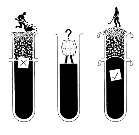
Without the assistance of root-binding and sward cover, surface stability on hard porous surfaces can only be achieved by choosing materials of mixed particle-size composition and angular shape. The pore system must transmit water at more than 2–3 mm/h (1/10 in) but must not empty by gravity, drying out instead by the relatively slow process of evaporation upwards, e.g. a layer of fine-to-coarse sand, less than 150 mm (6 in) deep, placed over a bed of fine gravel. (Refer back to section 4.2 for a full discussion of the significance of critical tension and its role in the retention of water.) Water-binding is an essential feature of the surface layer, contributing to tractive efficiency and resistance to wind erosion.
The most readily available materials used for the surface are by-products from stone quarries involved in rock crushing. These are mechanically crushed rocks with particle-size composition as summarized in Table 13.1 and Figure 13.1. A typical example, SN9, is included in Table 7.1. Because the particles are sharply angular and vary in size they will interpack to form a relatively dense, rigid surface, retentive of water when placed in a thin layer over gravel. Drainage is controlled by the rock dust component of silt- and clay-sized particles present. When fine particle segregation reduces the infiltration rate of the surface to something less than 2–3 mm (1/10 in)/h, even short bursts of intense rainfall may give rise to surface flow.
Based on a survey of 15 samples, representative of nine different, marketed products available in the 1970s (Table 13.1), hard porous materials are likely to contain of the order of 30–40% fine gravel, 15–20% medium-plus-fine sand, and 10–15% silt-plus-clay, with a fairly even spread between. However, this composition probably owes more to the ready availability of these by-product materials than to scientific investigation. Further experimentation could usefully explore the extent to which the silt-plus-clay component could be reduced and the gravel component eliminated. Despite the preponderence of coarse particles in hard porous, surfacing materials, it is the finer material packed into the pores between the larger particles that ultimately controls the rate at which water will pass through. Though the hydraulic conductivity of these materials, measured in the laboratory or predicted from particle-size composition D 10, is likely to indicate values of the order of 25 mm/hour (1 in), irrigation water applied to established surfaces at rates one-tenth of this have been observed to pond. This discrepancy is to be related to the practical problem of air entrapment. It further emphasizes the importance of adequately grading the surface so that any temporary excess of rainfall over infiltration can clear all the way to a catchment drain at the periphery.
Wind and water movement inevitably result in the finest particles being either blown away or washed downslope. With soft rock materials, such as 1–3, 9–11 and 15 in Table 13.1, fine-particle replenishment will result from
TABLE 13.1 Crushed rock materials used in the 1970s for hard porous, water-bound, reacreation surfaces
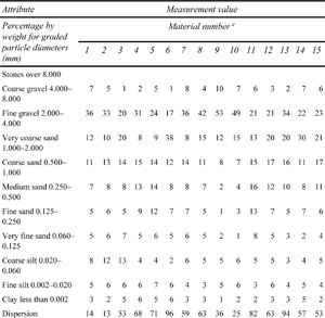
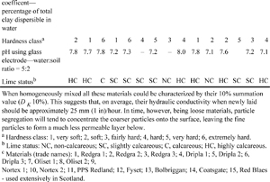
wear so long as coarse-particle replenishment is maintained by topdressing. With a surfacing material from a hard rock source it could be that the dust component itself may require replenishment from time to time, but before moving in this direction, it would be as well to seek clear evidence of need from an analytical survey.
As these hard porous materials can be expensive there is no point in building up a layer thicker than is necessary to avoid stud penetration through to the gravel layer beneath. Experience points to a minimum, consolidated depth of 35–40 mm (l 3/8–1 1/2 in).
13.2.4
The sub-structure
Without trying to provide for extreme conditions, it would be reasonable to design hard porous pitches in Britain to cope with a maximum, steady discharge of the order of 6 mm (1/4 in) per hour through the gravel drainage bed. In most circumstances this will be more than adequate.
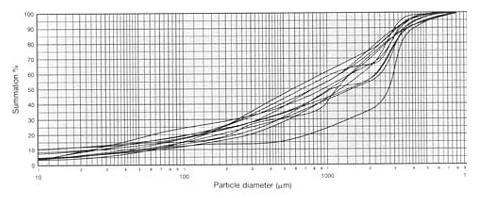
FIGURE 13.1 Summation graph showing the particle-size composition of the hard porous materials listed in Table 13.1. The unshaded area defines the particle-size zone typical of materials that have been used traditionally for surfacing hard porous pitches. Because of the very wide range of particle sizes present in crushed rock materials there is a great deal of scope for reconsolidation by interpacking. To determine D K from Figure 13.1 and hence, by reference to Figure 7.7, predict the order of hydraulic conductivity to be expected from these materials when settled on site, use the particle-size value which corresponds with the 10% value on the summation scale. This prediction procedure indicates that hydraulic conductivities between 5 and 30 mm/h will be typical. Thus, as experience confirms, surface flow may well lead to localized ponding during bursts of intense rainfall unless the surface is graded to ensure that all excess will clear to the periphery.
The gravel drainage bed itself is usually over-generously designed and can offer a considerable amount of spare, temporary storage capacity. The actual capacity will depend on the depth of the gravel bed and the slope of the base, but could well extend to an amount in excess of 150 000 litres (33 000 gallons). Where a pitch is located at the foot of a slope and is liable to flooding, a catchment drain will be required to intercept extraneous water arriving as runoff from the hill above. However, the drain may not be adequate to cope with exceptional storm conditions and it might then be helpful if the storage capacity beneath the pitch could be utilized as a flood-control reservoir. This could be achieved by linking the gravel bed through to the gravel fill above the pipe in the catchment-drain trench, making it possible, under exceptional circumstances, to allow excess water to overflow from the catchment drain trench into the available space for temporary storage in the gravel bed beneath the pitch.
If the crushed rock forming the playing surface is to be encouraged to remain water-bound and minimally disrupted by frost, there must be no capillary continuity between it and the underlying soil. This is something which the gravel bed must achieve in addition to drainage, and explains why solid gravel is to be preferred to cinder.
13.3
Two standard designs for low cost, quick-draining, water-bound, hard porous pitches
13.3.1
Theory
An area of a size suitable for a single pitch can be designed to grade uniformly, all in one direction, or either way off a central, goal-to-goal crown. The first option might be more appropriate for a site which already slopes in one direction; the second would be a good option for a flat site, for example, a pitch within a running track. With clearance one way there is a risk that surface flow will so accumulate downslope that, during heavy rain, surface erosion becomes a real possibility. With a crown, the change in slope across the midline tends to visually exaggerate the steepness of the slopes that fall away either side, unless the grade change at the crown is very gradual.Figure 13.2 illustrates the two options by means of transverse sections across the width of the pitch.
The gradients chosen for the surface must be a compromise, arbitrarily chosen to enhance surface flow and avoid ponding while, at the same time, minimizing the risk of erosion and not noticeably interfering with play. The gradient of 1:90 chosen for the surface sloping all in one direction is probably the maximum that should be risked for the 60 m (66 yard) run across the width of a pitch. A lesser gradient might seem a safer option but this will increase the risk of localized ponding in areas left slightly dished after construction or becoming dished subsequently as a result of differential settlement. The greatest risk of erosion damage arises when areas ponded upslope eventually overflow, causing gullying to start at the point of release. A steeper slope will keep water on the move but, on a long slope, the risk of sheet erosion will increase as runoff accumulates and the speed of flow accelerates. Thus, though a slope that will help discharge surface water to the periphery is desirable, the length in any one direction should be kept to a minimum. This means orienting the slope across the width of the pitch, ideally splitting it to run either way off a goal-to-goal crown.
Creating a surface that will initially shed excess water very effectively is not enough: it must remain effective. This requires that all layers are properly consolidated at time of construction and any adverse effects of longterm settlement are taken out by appropriate topdressing with additional surface material.
At either side of the pitch there may have to be drains organized to intercept water encroaching from outside the playing area, and the same system can be used to clear surface and ground water directed to it off the pitch. An additional pipe, running lengthwise down the pitch, may be used to allow a marked reduction in the depth of gravel required to form the drainage bed beneath a pitch sloping all one way. Under a crowned pitch, the depth of trench gravel required to clear the drainage water all the way to either peripheral drain is only of the order of 100 mm (4 in). This is not much more than would be required to form a satisfactory capillary break between the underlying soil and the layer of crushed rock forming the water-bound surface. Thus, for a crowned pitch, the only pipes required are the catchment drains at the periphery.
Traps and inspection chambers should be installed at either end of each pipe run to assist with the interception and clearance of silt. The looseness of the crushed rock surface and the sorting effect of treading disturbance and frost heave will allow the fine, water-holding particles to escape into the drainage system. As this risk is greatest during construction and the initial, settling down period, inspection prior to handover would be a wise precaution.
The two pitches illustrated in Figure 13.2 aim to offer the best, low-cost alternatives for workaday pitches, designed to carry all the hard wear from which the grass pitches in a playing field need to be protected. The general form of the surface is established by the form into which the exposed, subsoil surface is graded, then above this, layers of trench gravel, blinding sand and crushed rock, hard porous material can be laid, each of uniform thickness. The trench gravel for the crowned pitch should be 105 mm (41/4 in) deep, and for the pitch
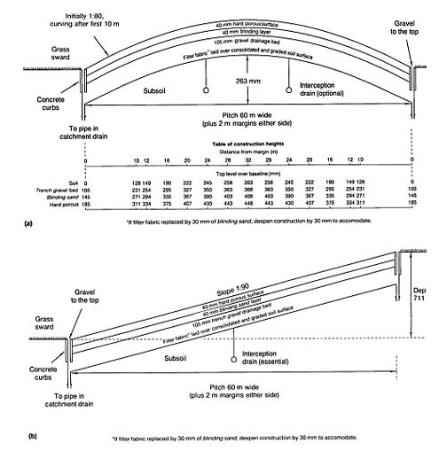
FIGURE 13.2 Transverse sections of hard porous pitches: (a) sloping either way off a central, goal to goal crown; (b) sloping uniformly across the pitch.
sloping all one way, 210 mm (81/2 in) deep or, with an additional central pipe, 105 mm (41/4 in) deep. The layers of blinding sand and the hard porous surface should both be about 40 mm (l1/2 in) deep, irrespective of other details of the construction.
Two catchment drains are shown running longitudinally down either side of each pitch. Only on the pitch with 105 mm (41/4 in) deep drainage bed, sloping all one way, is it necessary to introduce one additional drain to run longitudinally down the centre. The grading and linkage of the drain pipes will depend on the location of the final outfall and all the other factors normally involved in the design of pipe, underdrainage systems (section 2.1).
13.3.2
Calculation
Pitch sloping all one way
To calculate H, the depth of the gravel bed, follow procedures described in Appendix E2.2 (also refer to Figure 13.2(b)). The following are known:
| V - the overall design rate | 6 mm/h |
| S - the width of the pitch including surrounds (drain to drain) | 64 000 mm |
| G/S — the slope | 1/90 |
| K - the hydraulic conductivity of the trench gravel used to form the bed | 100 000 mm/h. |
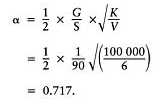
Step 1: determine a using equation (E.31):
Step 2: determine β using relationship to a as described in the graph, Figure 13.3(a): when α =0.717, β=0.435.
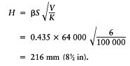
Step 3: from equation (E.32)
giving
Knowing H, the depth of the gravel bed, and G, the difference in height either side of the pitch we can if necessary calculate any one of S, K or V, knowing the other two. This can be done using equations (E.31) and (E.32), provided we can obtain values for α and ß.
Step 1: from equations (E.31) and (E.32) we can relate α to ß as follows
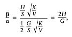
and
This is a straight-line relationship, passing through the origin.
Step 2: plot the straight-line relationship between α and β on the graph (Figure 13.3(a)) which describes the physical relationships involved in the actual construction. This can be done by making use of the fact that when α= 0, (β=0 and when α=l, β=2H/G, i.e.
The intersection between this line and the curve on the graph gives values α=0.717, β= 0.435.
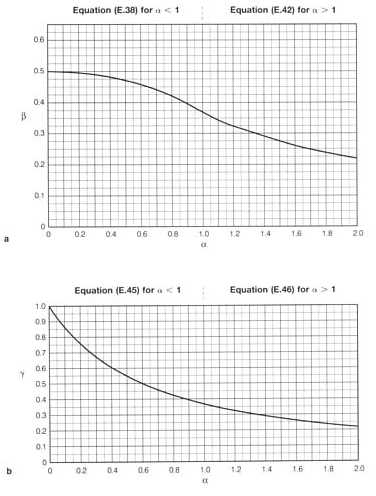
FIGURE 13.3 (a) Relationship between α and β for pitches with drainage bed sloping all one way, using equations (E.38) and (E.42). (b) Relationship between α and γ for crowned pitches with drainage bed sloping down to either side off a central crown, using equations (E.45) and (E.46).
Step 3: Using these values for α and β, equations (E.31) and (E.32) can then be used to obtain values for either S, K or V.
Instead of using 210 mm of gravel it may well be cheaper, and just as efficient to introduce an additional pipe drain to run lengthwise down the centre of the pitch, reducing S to 32 000 mm and gravel depth H to 105 mm (41/4 in).
Pitch clearing excess water to either side off a goal-to-goal crown
In the following calculations it is assumed that no gradient should exceed 1:80 and it would be practically more desirable to have a uniform, fixed depth for the gravel drainage bed.
To fix precise values to key features of the construction, follow calculation procedures described in Appendix E.2.3 and the definitions listed below; also refer to Figure 13.2 (a).
| V | - | the overall design rate (6 mm/h) |
| G/S | - | the 1:80 gradient for the straight portion at either edge of the cross-sectional profile of the pitch |
| H | - | the depth of the gravel drainage bed (mm) |
| K | - | the hydraulic conductivity of the trench gravel used to form the drainage bed (100 000 mm/h) |
| x 1 | - | the total distance from the centre of the pitch to a peripheral drain, measured horizontally (mm) |
| x | - | any distance from a drain measured horizontally across the pitch (mm) |
| x 0 | - | the point along the horizontal above which the curving portion of the profile begins (mm) |
| g | - | the height above the horizontal base line (mm). |
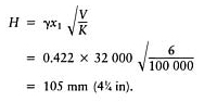
Step 1: determine a using equation (E.31):
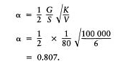
Step 2: determine γ using relationship to a as described in the graph Figure 13.3(b): when α =0.807, γ=0.422.
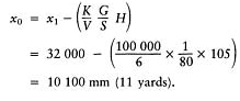
Step 3: using equation (E.51)

giving
Step 4: using Equation (E.47), determine x 0, the distance from a drain at the edge of the pitch that defines the point on the surface where the uniform, 1:80 gradient begins to fall off to a steadily curving profile over the crown.
Step 5: using equation (E.50), determine the height (mm) of the top of the soil formation surface above a series of base line values for x. Choose values for x that will facilitate construction of the profile required. Height g at point x (valid only for curved portion of profile):
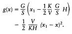
For x=10 100 mm (i.e.x0)
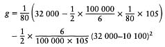
=126 mm (i.e. for distance of 10 100 mm at gradient of 1:80, rise=126 mm). Similarly, after simplifying the calculation to
| for | x=12 000mm | g=149 mm |
| x=16 000mm | g=190 mm | |
| x=20 000 mm | g=222 mm | |
| x=24 000 mm | g=245 mm | |
| x=28 000 mm | g=258 mm | |
| x=32 000 mm | g=263 mm, |
and again in reverse order for the far side of thecrown.
This profile is then repeated 105 mm, 145 mm and 185 mm higher, for the top of the gravel bed, the top of the layer of blinding sand and the top of the crushed rock, surfacing material respectively (Figure 13.2(a)).
A crowned profile of this form could well be considered for use elsewhere than for hard porous pitches, e.g. beneath a suitably resilient surface, such as an outside arena for horse riding.
13.3.3
Outline specification
1.The formation layer should be excavated and shaped to create a stable, consolidated surface of subsoil conforming exactly with one or other of the profiles illustrated in Figure 13.2. After initial site preparation the consolidated soil surface, covered with either filter fabric or 25 mm (1 in) of blinding sand, should be at a depth below the general level of the adjacent, undisturbed soil equal to the combined depth of the trench gravel, blinding sand and crushed rock layers used to create the drainage bed and playing surface. It is vital that the soil is disturbed as little as possible below excavation depth and is properly re-consolidated every 150 mm (6 in) where used as fill. Differential settlement after the whole construction is in place is a major hazard and care is required to minimize this risk.
2.Install perimeter drains along each side so as to intercept water reaching the area from surrounding land and to take water flowing out of the gravel foundation. The drains should run just inside a concrete edging, the trench at least 200 mm (8 in) wide. Pipes should be between 100 and 150 mm (4 and 6 in) in diameter according to the size of the area and the amount of water likely to be intercepted from surrounding land. See back to section 13.2.4 for a modification where precautions need to be taken against a risk of site flooding.
Ideally, the pipes should be laid to a fall of not less than 1:100, with depth to invert not less than 300 mm (12 in) below the level of the formation surface. Permeable backfill should be trench gravel, finishing at least 50 mm (2 in) proud of the formation surface so as to protect the freely porous backfill from becoming contaminated by soil as the work proceeds. They should link with other pipes via chambers with silt traps, and have access points along their length to aid inspection and jet clearance of silt.
If additional, longitudinal drains are used within the pitch area they should be similar to those at the periphery.
3.Round-topped precast concrete edging, 150 ×50 mm (6×2 in), should be laid round four sides, bedded and haunched in concrete so that the top lies flush with the final surface level.
4.After applying total weedkiller to the formation surface and margins, the formation soil surface should be blinded with 25 mm (1 in) of blinding sand, or synthetic fabric filter, anchored by tucking the edge down the inner wall of the peripheral drain trenches.
5.Lay and spread a foundation, drainage layer of trench gravel to the depth indicated as appropriate in Figure 13.2. If a somewhat angular gravel is used this will assist trafficking during construction. Take pains to consolidate and true the surface to the required configuration.
6.Evenly blind the gravel drainage bed with 40 mm (1 1/2 in) of blinding sand; true and consolidate.
7.Lay and spread approved, crushed-rock surfacing material to an even, consolidated depth of 40 mm (1 1/2 in) so as to finish flush with the top of the edging.
8.Initially the surface will be loose and inclined to be churned up by use unless gently firmed down, for example, by the continuous patter of feet when moist. Topdress with crushed rock to true off to the required profile overall.
9.The build-up over the level pitch margins and peripheral drains should conform with that of the pitch in general. As experience indicates where surface runoff accumulates, make local provision to clear ponded water directly into the gravel bed through a layer of fabric filter, buried at shallow depth beneath a cosmetic covering of the gravel fraction sieved out of the crushed-rock surfacing material.
13.4
Maintenance
13.4.1
Special problems likely to be revealed soon after construction
The main task of maintenance on water-bound, hard porous pitches is to keep the surface uniform in composition, consolidated and true, despite the tendency for a particulate, multi-particle-sized material to segregate when churned up by energetic play. This problem will be worst immediately after construction but should decrease as more effective particle packing allows the surface to stabilize.
Differential settlement, which is also likely to be most pronounced in the initial years following construction, may be sufficient to cause local, dished areas, liable to accumulate surface runoff. These should be eliminated by topdressing with more surface material before a deposit of eroded fine particles builds up to adversely affect infiltration. A reserve of 4–6 tonne of surfacing material will be required annually for re-truing and the replacement of losses brought about by comminution and surface erosion.
Persistent problems of surface ponding should not occur if the surface is smooth and suitably graded so as to clear all surface water to the periphery. However, if designed too flat, problems of persistent surface ponding may require attention. This can be approached in two ways. A disc, slicing device can be used to slit through the surface material and reach the clean gravel below. If the slit is oriented across slope and filled with coarse particles, either brushed off the surface or separated by sieving from the bulk reserve, it will function to intercept surface flow. However, any beneficial effect is unlikely to persist for more than a few months as surface wear will soon ensure fineparticle invasion of the coarse backfill. Alternatively, install, a small, 150 mm (6 in) diameter, readily accessible outfall in the base of each major depression so that it can be opened up to clear ponded water quickly when necessary. These covered outlets should take the form of wide-necked funnels, each anchored with its neck in the underlying gravel bed and bowl opening just below the surface. The inlet should be protected against silting by covering with a renewable, fabric filter, shielded against physical damage by covering with a removable, wooden cap, lying flush with the surface.
13.4.2
Surface renovation and surface protection
Routine maintenance involves luting, drag matting, brushing and rolling. Scarification will also be required, but only when the top needs opening up to help integrate a surface topdressing. Since agitation will inevitably lead to segregation of coarse particles onto the surface, rolling should be carried out when the whole top is moist. This will make it easier for the coarse particles to be pressed back into the finer material below. If not, they will remain as a loose covering, unfavourable to efficient traction. The late F.W.Smith, the first Grounds Superintendent at the University of Lancaster, and great advocate of hard porous surfaces, used to strongly advise rolling in the rain.
Provision for irrigation should be considered essential as the shallow, surface layer will readily dry out in hot weather, and then be vulnerable to windblow.
Hard porous materials are often wrongly described as ‘all weather’. In fact there are two weather-induced conditions when use should not be contemplated. Do not risk loosening the surface if irrigation cannot be used during hot weather to prevent the fine particles required for water-binding being selectively removed by wind erosion. On no account use a hard porous surface after frost until it has thawed out and been thoroughly re-consolidated by rolling. The expansion that follows the freezing of retained moisture may lead to considerable surface heave.
Salt will help to keep this type of surface ‘greasily’ moist through a dry spell and less inclined to freeze up in winter, but it will readily wash out and then encourage the leaching away of any clay component.
13.4.3
Manpower
Though much more suitable for programmed use than the normal, soil-based, grass surface, to sustain performance, provision must be made for frequent surface renovation. In practice, therefore, this type of non-grass facility should not be looked upon as allowing any very significant saving in maintenance manpower.
13.5
Further developments in the hard porous approach
13.5.1
Surfaces for schooling horses
If the blinding sand layer of a hard porous construction is overlaid with 100 mm (4 in) depth of topsoil sand, or any other medium approved for the purpose, it might well serve for the schooling of horses. In these circumstances the sand, or special alternative layer, should be placed over a layer of fabric filter to facilitate surface renewal without risk to the integrity of the drainage bed. Provision for irrigation will be necessary to keep the surface firmly water-bound.
13.5.2
Nottinghamshire envelope system
Peter L.K.Dury, working in the Nottinghamshire playing-field service, has developed the idea of enveloping hard porous and dune-sand-like materials within free-draining and tractively efficient, filter fabrics (geotextiles). The early promise of this approach has now led on to diversification into a wide range of amenity applications from safe surfaces for child play to cricket pitches, tennis courts and full-scale pitches for hockey and soccer. All of these have infill and surface fabrics matched to the special requirements of the user. Here then is a halfway house between the very expensive, wholly synthetic surfaces, claimed to be allweather, and the much less sophisticated but relatively cheap workhorse, the original hard porous pitch. They all aim to provide surfaces better suited than grass for intensive, programmed use.