

Maintaining storage infrastructure
As an IT environment grows and is renewed, so must the storage infrastructure. One of the many benefits that the IBM FlashSystem family software (IBM Spectrum Virtualize) provides, is to greatly simplify the storage management tasks that system administrators need to perform.
This chapter highlights guidance for the maintenance activities of storage administration by using the IBM FlashSystem family software that is installed on the product. This guidance can help you to maintain your storage infrastructure with the levels of availability, reliability, and resiliency that are demanded by today’s applications, and to keep up with storage growth needs.
This chapter concentrates on the most important topics to consider in IBM FlashSystem administration so that you can use it as a checklist. It also provides best practice tips and guidance. To simplify the Storage Area Network (SAN) storage administration tasks that you use often, such as adding new users, storage allocation and removal, or adding and removing a host from the SAN, create step-by-step, standard procedures for them.
The discussion in this chapter focuses on the IBM FlashSystem 9200 for the sake of simplicity, using screen captures and command outputs from this model. The recommendations and practices that are discussed in this chapter are applicable to the following models:
•IBM FlashSystem 5010
•IBM FlashSystem 5015
•IBM FlashSystem 5030
•IBM FlashSystem 5035
•IBM FlashSystem 5100
•IBM FlashSystem 5200
•IBM FlashSystem 7200
•IBM FlashSystem 9100
•IBM FlashSystem 9200
|
Note: The practices that are described in this chapter were effective in many installations of different models of the IBM FlashSystem family. These installations were performed in various business sectors for various international organizations. They all had one common need: to manage their storage environment easily, effectively, and reliably.
|
This chapter includes the following topics:
10.1 User interfaces
The IBM FlashSystem family provides several user interfaces to allow you to maintain your system. The interfaces provide different sets of facilities to help resolve situations that you might encounter. The interfaces for servicing your system connect through the 1 Gbps Ethernet ports that are accessible from port 1 of each canister.
•Use the management graphical user interface (GUI) to monitor and maintain the configuration of storage that is associated with your clustered systems.
•Use the service assistant tool GUI to complete service procedures.
•Use the command-line interface (CLI) to manage your system.
The best practice recommendation is to use the interface most appropriate to the task you are attempting to complete. For example, a manual software update is best performed using the service assistant GUI or the CLI. Running fix procedures to resolve problems or configuring expansion enclosures can only be performed using the management GUI. The creation of many volumes with customized names is best performed using the CLI using a script. To ensure efficient storage administration, become familiar with all available user interfaces.
10.1.1 Management GUI
The management GUI is the primary tool that is used to service your system. Regularly monitor the status of the system using the management GUI. If you suspect a problem, use the management GUI first to diagnose and resolve the problem. Use the views that are available in the management GUI to verify the status of the system, the hardware devices, the physical storage, and the available volumes.
To access the Management GUI, start a supported web browser and go to https://<flashsystem_ip_address>, where the <flashsystem_ip_address> is the management IP address set when the clustered system is created.
For more information about the task menus and functions of the Management GUI, see Chapter 4 of Implementing the IBM System Storage SAN Volume Controller with IBM Spectrum Virtualize Version 8.4, SG24-8491.
10.1.2 Service assistant tool GUI
The service assistant interface is a browser-based GUI that can be used to service individual node canisters in the control enclosures.
|
Important: If used incorrectly, the service actions that are available through the service assistant can cause loss of access to data or even data loss.
|
You connect to the service assistant on one node canister by entering the service IP address. If there is a working communications path between the node canisters, you can view status information and perform service tasks on the other node canister by making the other node canister the current node. You do not have to reconnect to the other node. On the system itself, you can also access the service assistant interface by using the technician port.
The service assistant only provides facilities to help you service control enclosures. Always service the expansion enclosures by using the management GUI.
You can also complete the following actions using the service assistant:
•Collect logs to create and download a package of files to send to support personnel.
•Provide detailed status and error summaries.
•Remove the data for the system from a node.
•Recover a system if it fails.
•Install a code package from the support site or rescue the code from another node.
•Update code on node canisters manually.
•Configure a control enclosure chassis after replacement.
•Change the service IP address that is assigned to Ethernet port 1 for the current node canister.
•Install a temporary SSH key if a key is not installed and CLI access is required.
•Restart the services used by the system.
To access the Service Assistant Tool GUI, start a supported web browser and go to: https://<flashsystem_ip_address>/service, where <flashsystem_ip_address> is the service IP address for the node canister or the management IP address for the system on which you want work.
10.1.3 Command-line interface
The system CLI is intended for use by advanced users who are confident using a CLI. Up to 32 simultaneous interactive Secure Shell (SSH) sessions to the management IP address are supported.
Nearly all the functions that is offered by the CLI is available through the management GUI. However, the CLI does not provide the fix procedures that are available in the management GUI. Alternatively, use the CLI when you require a configuration setting that is unavailable in the management GUI.
Entering help in a CLI displays a list of all available commands. You have access to a few other UNIX commands in the restricted shell, such as grep and more, which are useful in formatting output from the CLI commands. Reverse-i-search (Ctrl+R) is also available. Table 10-1 shows a list of UNIX commands:
Table 10-1 UNIX commands available in the CLI
|
UNIX command
|
Description
|
|
grep
|
Filter output by keywords
|
|
more
|
Moves through output one page at a time
|
|
sed
|
Filters output
|
|
sort
|
Sorts output
|
|
cut
|
Removes individual columns from output
|
|
head
|
Display only first lines
|
|
less
|
Moves through the output one page at a time
|
|
tail
|
Display only last lines
|
|
uniq
|
Hides any duplicates in the output
|
|
tr
|
Translates characters
|
|
wc
|
Counts lines, words and characters in the output
|
|
history
|
Display command history
|
|
scp
|
Secure copy protocol
|
For more information about command reference and syntax, see the following resources:
Service command-line interface
Service CLI commands also can be run on a specific node. To run such a command in this way, log in to the service IP address of the node that requires servicing.
For more information about the use of the service command line, see this IBM Documentation web page.
USB command interface
When a USB flash drive is inserted into one of the USB ports on a node, the software searches for a control file (satask.txt) on the USB flash drive and runs the command that is specified in the file. Using the USB flash drive is required in the following situations:
•When you cannot connect to a node canister in a control enclosure using the service assistant and you want to see the status of the node.
•When you do not know, or cannot use, the service IP address for the node canister in the control enclosure and must set the address.
•When you have forgotten the superuser password and must reset the password.
For more information about the use of the USB port, see this IBM Documentation web page.
Technician port
The technician port is an Ethernet port on the back window of the IBM FlashSystem product that you can use to configure the node. You can use the technician port to do most of the system configuration operations, which includes the following tasks:
•Defining a management IP address
•Initializing a new system
•Servicing the system
For more information about the use of the Technician port, see this IBM Documentation web page.
10.2 Users and groups
Almost all organizations have IT security policies that enforce the use of password-protected user IDs when their IT assets and tools are used. However, some storage administrators still use generic shared IDs, such as superuser, admin or root, in their management consoles to perform their tasks. They might even use a factory-set default password. Their justification might be a lack of time, forgetfulness, or the fact that their SAN equipment does not support the organization’s authentication tool.
SAN storage equipment management consoles often do not provide direct access to stored data, but one can easily shut down (accidentally or deliberately) a shared storage controller and any number of critical applications along with it. Moreover, having individual user IDs set for your storage administrators allows much better auditing of changes if you must analyze your logs.
IBM FlashSystem supports the following authentication methods:
•Local authentication using a password
•Local authentication using SSH keys
•Remote authentication using Lightweight Directory Access Protocol (LDAP) (Microsoft Active Directory or IBM Security Directory Server)
Local authentication is appropriate for small, single enclosure environments. Larger environments with multiple clusters and enclosures benefit from the ease of maintenance that is achieved by using single sign-on (SSO) that uses remote authentication using LDAP, for example.
By default, the following user groups are defined:
•Monitor: Users with this role can view objects but cannot manage the system or its resources. Support personnel can be assigned this role to monitor the system and to determine the cause of problems. This role must be assigned to the IBM Storage Insights user. For more information about IBM Storage Insights, see Chapter 9, “Implementing a storage monitoring system” on page 387.
•Copy Operator: Users with this role have monitor role privileges and can create, change, and manage all Copy Services functions.
•Service: Users can set the time and date on the system, delete dump files, add and delete nodes, apply service, and shut down the system. Users can also perform the same tasks as users in the monitor role.
•Administrator: Users with this role can access all functions on the system except those that deal with managing users, user groups, and authentication.
•Security Administrator: Users with this role can access all functions on the system, including managing users, user groups, and user authentication.
•Restricted Administrator: Users with this role can complete some tasks, but are restricted from deleting certain objects. Support personnel can be assigned this role to solve problems.
•3-Site Administrator: Users with this role can configure, manage, and monitor 3-site replication configurations through certain command operations only available on the 3-Site Orchestrator.
•vStorage Application Programming Interface (API) for Storage Awareness (VASA) Provider: Users with this role can manage virtual volumes (vVols) that are used by VMware vSphere and managed through IBM Spectrum Control software.
•FlashCopy Administrator: Use the FlashCopy commands to work with FlashCopy system methods and functions. For more information, see this IBM Documentation web page.
In addition to standard groups, you can also configure ownership groups to manage access to resources on the system. An ownership group defines a subset of users and objects within the system. You can create ownership groups to further restrict access to specific resources that are defined in the ownership group.
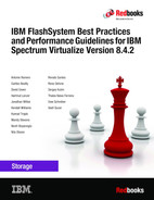
Users within an ownership group can view or change only resources within the ownership group in which they belong. For example, you can create an ownership group for database administrators to provide monitor-role access to a single pool used by their databases. Their views and privileges in the management GUI are automatically restricted, as shown in Figure 10-1.
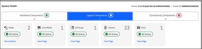
Figure 10-1 System Health Logical Components view
Figure 10-2 shows the Dashboard System Health hardware components view.
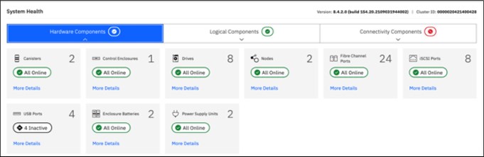
Figure 10-2 System Health Hardware Components view
Regardless of the authentication method you choose, complete the following tasks:
•Create individual user IDs for your Storage Administration staff. Choose user IDs that easily identify the user and meet your organization’s security standards.
•Include each individual user ID into the UserGroup with only enough privileges to perform the required tasks. For example, your first-level support staff probably only require Monitor group access to perform their daily tasks, whereas second-level support might require Restricted Administrator access. Consider using Ownership groups to further restrict privileges.
•If required, create generic user IDs for your batch tasks, such as Copy Services or Monitoring. Include them in a Copy Operator or Monitor UserGroup. Never use generic user IDs with the SecurityAdmin privilege in batch tasks.
•Create unique SSH public and private keys for each administrator requiring local access.
•Store your superuser password in a safe location in accordance to your organization’s security guidelines and use it only in emergencies.
10.3 Volumes
A volume is a logical disk that is presented to a host by an I/O group (pair of nodes), and within that group a preferred node serves I/O requests to the volume.
When you allocate and deallocate volumes to hosts, consider the following guidelines:
•Before you allocate new volumes to a server with redundant disk paths, verify that these paths are working well, and that the multipath software is free of errors. Fix disk path errors that you find in your server before you proceed.
•When you plan for future growth of space efficient volumes (VDisks), determine whether your server’s operating system supports the particular volume to be extended online. AIX V6.1 TL2 and lower, for example, do not support online expansion of rootvg logical unit numbers (LUNs). Test the procedure in a nonproduction server first.
•Always cross-check the host LUN ID information with the vdisk_UID of the IBM FlashSystem. Do not assume that the operating system recognizes, creates, and numbers the disk devices in the same sequence or with the same numbers as you created them in the IBM FlashSystem.
•Ensure that you delete any volume or LUN definition in the server before you unmap it in the IBM FlashSystem. For example, in AIX, remove the hdisk from the volume group (reducevg) and delete the associated hdisk device (rmdev).
•Consider enabling volume protection by using chsystem vdiskprotectionenabled yes -vdiskprotectiontime <value_in_minutes>. Volume protection ensures that some CLI actions (most of those that either explicitly or implicitly remove host-volume mappings or delete volumes) are policed to prevent the removal of mappings to volumes or deletion of volumes that are considered active; the system detected I/O activity to the volume from any host within a specified time period (15 - 1440 minutes).
|
Note: Volume protection cannot be overridden using the -force flag in the affected CLI commands. Volume protection must be disabled to carry on an activity that is blocked.
|
•Ensure that you explicitly remove a volume from any volume-to-host mappings and any copy services relationship to which it belongs before you delete it.
|
Attention: You must avoid the use of the -force parameter in rmvdisk.
|
•If you issue the svctask rmvdisk command and it still has pending mappings, the IBM FlashSystem prompts you to confirm the action and this is a hint that you might have done something incorrectly.
•When you are deallocating volumes, plan for an interval between unmapping them to hosts (rmvdiskhostmap) and deleting them (rmvdisk). The IBM internal Storage Technical Quality Review Process (STQRP) asks for a minimum of a 48-hour period, and having at least a one business day interval so that you can perform a quick backout if you later realize you still need some data on that volume.
For more information about volumes, see Chapter 5, “Volume types” on page 199.
10.4 Hosts
A host is a computer that is connected to the SAN switch through Fibre Channel (FC), iSCSI, and other protocols.
When you add and remove hosts in the IBM FlashSystem, consider the following guidelines:
•Before you map new servers to the IBM FlashSystem, verify that they are all error free. Fix errors that you find in your server and IBM FlashSystem before you proceed. In the IBM FlashSystem, pay special attention to anything inactive in the lsfabric command.
•Plan for an interval between updating the zoning in each of your redundant SAN fabrics, such as at least 30 minutes. This interval allows for failover to occur and stabilize, and for you to be notified if unexpected errors occur.
•After you perform the SAN zoning from one server’s host bus adapter (HBA) to the IBM FlashSystem, you should list its worldwide port name (WWPN) by using the lshbaportcandidate command. Use the lsfabric command to certify that it was detected by the IBM FlashSystem nodes and ports that you expected. When you create the host definition in the IBM FlashSystem (mkhost), try to avoid the -force parameter. If you do not see the host’s WWPNs, it might be necessary to scan fabric from the host. For example, use the cfgmgr command in AIX.
For more information about hosts, see Chapter 8, “Configuring hosts” on page 367.
10.5 Software updates
Because the IBM FlashSystem might be at the core of your disk and SAN storage environment, the software update procedure requires planning, preparation, and verification. However, with the appropriate precautions, an update can be conducted easily and transparently to your servers and applications. This section highlights applicable guidelines for the IBM FlashSystem update.
Most of the following sections explain how to prepare for the software update. These sections also present version-independent guidelines on how to update the IBM FlashSystem family systems and flash drives.
Before you update the system, ensure that the following requirements are met:
•The latest update test utility is downloaded from IBM Fix Central to your management workstation. For more information, see this IBM Fix Central web page.
•The latest system update package is downloaded from IBM Fix Central to your management workstation.
•All node canisters are online.
•All errors in the system event log are addressed and marked as fixed.
•There are no volumes, MDisks, or storage systems with Degraded or Offline status.
•The service assistant IP is configured on every node in the system.
•The system superuser password is known.
•The system configuration is backed up and saved (preferably off-site), as shown in Example 10-11 on page 512.
•You can physically access the hardware.
The following actions are not required, but are recommended to reduce unnecessary load on the system during the update:
•Stop all Metro Mirror, Global Mirror, or HyperSwap operations.
•Avoid running FlashCopy operations.
•Avoid migrating or formatting volumes.
•Stop collecting IBM Spectrum Control performance data for the system.
•Stop automated jobs that access the system.
•Ensure that no other processes are running on the system.
•If you want to update without host I/O, then shut down all hosts.
|
Note: For customers who purchased the IBM FlashSystem 9200 with a three-year warranty (9848 Models AG8 and UG8), with Enterprise Class Support (ECS) is included. This support entitles the customer to two code upgrades per year, which are performed by IBM (for total of six across the three-year warranty).
These upgrades are done by the IBM dedicated Remote Code Load (RCL) team or, where remote support is not allowed or enabled, by an onsite Systems Service Representative (SSR). A similar optional service is available for the IBM FlashSystem 7200.
For more information about ECS, see IBM FlashSystem 9200 8.4.2 Documentation - Enterprise Class Support (ECS).
|
10.5.1 Deciding the target software level
The first step is to determine your current and your target IBM FlashSystem software level.
Using the example of an IBM FlashSystem 9200, log in to the web-based GUI and find the current version. Either from the right side of the top menu drop-down line, click the question mark symbol (?) and select About IBM FlashSystem 9200 to display the current version or select Settings → System → Update System to display both current and target levels.
Figure 10-3 shows the Update System output window and displays the code levels. In this example, the software level is 8.4.2.0.
Figure 10-3 Update System output window
Alternatively, if you use the CLI, run the svcinfo lssystem command. Example 10-1 shows the output of the lssystem CLI command and where the code level output can be found.
Example 10-1 lssystem command
IBM_FlashSystem:IBM Redbook FS:superuser>lssystem|grep code
Version 8.4.2.0 (build 154.20.2109031944000)
IBM FlashSystem software levels are specified by four digits in the following format (in our example V.R.M.F = 8.4.2.0):
•V is the major version number
•R is the release level
•M is the modification level
•F is the fix level
Use the latest IBM FlashSystem release unless you have a specific reason not to update, such as the following examples:
•The specific version of an application or other component of your SAN Storage environment has a known problem or limitation.
•The latest IBM FlashSystem software release is not yet cross-certified as compatible with another key component of your SAN storage environment.
•Your organization has mitigating internal policies, such as the use of the “latest release minus 1” or requiring “seasoning” in the field before implementation in a production environment.
•For more information, see Spectrum Virtualize Family of Products Upgrade Planning.
Obtaining the software packages
To obtain a new release of software for a system update, see IBM Fix Central and follow these steps:
1. From the Product selector list, type IBM FlashSystem 9200 (or whatever model is appropriate in your environment).
2. From the Installed Version list, select the current software version level that was determined in 10.5.1, “Deciding the target software level” on page 456.
3. Select Continue.
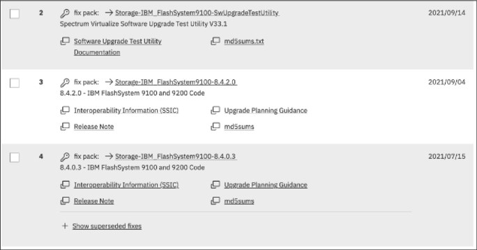
Figure 10-4 Fix Central software packages
5. Select Continue.
6. Click the option button for your preferred download options and click Continue.
7. Enter your machine type and serial number.
8. Select Continue.
9. Read the terms and conditions and then, select I Agree.
10. Select Download Now and save the three files onto your management computer.
10.5.2 Hardware considerations
Before you start the update process, always check whether your IBM FlashSystem hardware and target code level are compatible.
If part or all your current hardware is not supported at the target code level that you want to update to, replace the unsupported hardware with newer models before you update to the target code level.
Conversely, if you plan to add or replace hardware with new models to an existing cluster, you might have to update your IBM FlashSystem code first.
10.5.3 Update sequence
Check the compatibility of your target IBM FlashSystem code level with all components of your SAN storage environment (SAN switches, storage controllers, server HBAs) and its attached servers (operating systems and eventually, applications).
Applications often certify only the operating system that they run under and leave to the operating system provider the task of certifying its compatibility with attached components (such as SAN storage). However, various applications might use special hardware features or raw devices and certify the attached SAN storage. If you have this situation, consult the compatibility matrix for your application to certify that your IBM FlashSystem target code level is compatible.
The IBM FlashSystem Supported Hardware List provides the complete information for using your IBM FlashSystem SAN storage environment components with the current and target code level. For links to the Supported Hardware List, Device Driver, Firmware, and Recommended Software Levels for different products and different code levels, see this IBM Support web page.
By cross-checking the version of IBM FlashSystem is compatible with the versions of your SAN environment components, you can determine which one to update first. By checking a component’s update path, you can determine whether that component requires a multistep update.
If you are not making major version or multi-step updates in any components, the following update order is recommended to avoid eventual problems:
1. SAN switches or directors
2. Storage controllers
3. Servers HBAs microcode and multipath software
4. IBM FlashSystem
5. IBM FlashSystem internal Non-Volatile Memory express (NVMe) drives
6. IBM FlashSystem Serial Attached SCSI (SAS) attached solid-state drive (SSD)
|
Attention: Do not update two components of your IBM FlashSystem SAN storage environment simultaneously, such as an IBM FlashSystem 9200 and one storage controller. This caution is true even if you intend to do it with your system offline. An update of this type can lead to unpredictable results, and an unexpected problem is more difficult to debug.
|
10.5.4 SAN fabrics preparation
If you are using symmetrical, redundant, independent SAN fabrics, preparing these fabrics for an IBM FlashSystem update can be safer than hosts or storage controllers. This statement is true assuming that you follow the guideline of a 30-minute minimum interval between the modifications that you perform in one fabric to the next. Even if an unexpected error brings down your entire SAN fabric, the IBM FlashSystem environment continues working through the other fabric and your applications remain unaffected.
Because you are updating your IBM FlashSystem, also update your SAN switches code to the latest supported level. Start with your principal core switch or director, continue by updating the other core switches, and update the edge switches last. Update one entire fabric (all switches) before you move to the next one so that a problem you might encounter affects only the first fabric. Begin your other fabric update only after you verify that the first fabric update has no problems.
If you are not running symmetrical, redundant, independent SAN fabrics, fix this problem as a high priority because it represents a single point of failure.
10.5.5 Storage controllers preparation
As critical as with the attached hosts, the attached storage controllers must correctly handle the failover of MDisk paths. Therefore, they must be running supported microcode versions and their own SAN paths to IBM FlashSystem must be free of errors.
10.5.6 Hosts preparation
If the appropriate precautions are taken, the IBM FlashSystem update is not apparent to the attached servers and their applications. The automated update procedure updates one IBM FlashSystem node at a time, while the other node in the I/O group covers for its designated volumes.
However, to ensure that this feature works, the failover capability of your multipath software must be working correctly. This capability can be mitigated by enabling NPIV if your current code level supports this function. For more information about N_Port ID Virtualization (NPIV), see Chapter 8, “Configuring hosts” on page 367.
Before you start IBM FlashSystem update preparation, check the following items for every server that is attached to IBM FlashSystem that you update:
•The operating system type, version, and maintenance or fix level
•The make, model, and microcode version of the HBAs
•The multipath software type, version, and error log
For information about troubleshooting, see this IBM Documentation web page.
Fix every problem or “suspect” that you find with the disk path failover capability. Because a typical IBM FlashSystem environment can have hundreds of servers that are attached to it, a spreadsheet might help you with the Attached Hosts Preparation tracking process. If you have some host virtualization, such as VMware ESX, AIX Logical Partitions (LPARs), IBM Virtual I/O Server (VIOS), or Solaris containers in your environment, verify the redundancy and failover capability in these virtualization layers.
10.5.7 Copy services considerations
When you update an IBM FlashSystem family product that participates in an intercluster Copy Services relationship, do not update both clusters in the relationship simultaneously. This situation is not verified or monitored by the automatic update process and might lead to a loss of synchronization and unavailability.
You must successfully finish the update in one cluster before you start the next one. Try to update the next cluster as soon as possible to the same code level as the first one. Avoid running them with different code levels for extended periods.
10.5.8 Running the Upgrade Test Utility
It is a requirement that you install and run the latest IBM FlashSystem Upgrade Test Utility before you update the IBM FlashSystem software. For more information, see Software Upgrade Test Utility.
This tool verifies the health of your IBM FlashSystem storage array for the update process. It also checks for unfixed errors, degraded MDisks, inactive fabric connections, configuration conflicts, hardware compatibility, drive firmware, and many other issues that might otherwise require cross-checking a series of command outputs.
|
Note: The Upgrade Test Utility does not log in to storage controllers or SAN switches. Instead, it reports the status of the connections of the IBM FlashSystem to these devices. It is the users’ responsibility to check these components for internal errors.
|
You can use the management GUI or the CLI to install and run the Upgrade Test Utility.
Using the management GUI
To test the software on the system, complete these steps:
1. In the management GUI, select Settings → System → Update System.
2. Click Test Only.
3. Select the test utility that you downloaded from the Fix Central support site. Upload the Test utility file and enter the code level that you are planning to update to. Figure 10-5 shows the IBM FlashSystem management GUI window that is used to install and run the Upgrade Test Utility.

Figure 10-5 IBM FlashSystem Upgrade Test Utility using the GUI
4. Click Test. The test utility verifies that the system is ready to be updated. After the Update Test Utility completes, you are presented with the results. The results state that no warnings or problems were found, or directs you to more information about known issues that were discovered on the system.
Figure 10-6 shows a successful completion of the update test utility.
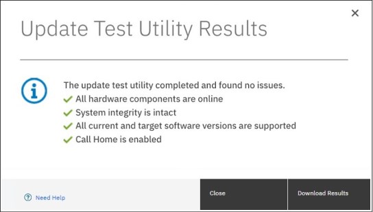
Figure 10-6 IBM FlashSystem Upgrade Test Utility completion panel
5. Click Download Results to save the results to a file.
6. Click Close.
Using the command line
To test the software on the system, complete these steps:
1. Using OpenSSH scp or PuTTY pscp, copy the software update file and the Software Update Test Utility package to the /home/admin/upgrade directory by using the management IP address of the IBM FlashSystem. Documentation and online help might refer to the /home/admin/update directory, which points to the same location on the system.
An example for the IBM FlashSystem 9200 is shown in Example 10-2.
Example 10-2 Copying the upgrade test utility to IBM FlashSystem 9200
C:>pscp -v -P 22 IBM_FlashSystem9200_INSTALL_upgradetest_33.1 [email protected]:/home/admin/upgrade
Looking up host "9.10.11.12" for SSH connection
Connecting to 9.10.11.12 port 22
We claim version: SSH-2.0-PuTTY_Release_0.74
Remote version: SSH-2.0-OpenSSH_8.0
Using SSH protocol version 2
No GSSAPI security context available
Doing ECDH key exchange with curve Curve25519 and hash SHA-256 (unaccelerated)
Server also has ssh-rsa host key, but we don't know it
Host key fingerprint is:
ecdsa-sha2-nistp521 521 a8:f0:de:cf:eb:fd:b4:74:9e:95:c7:bd:5c:f1:3b:b5
Initialised AES-256 SDCTR (AES-NI accelerated) outbound encryption
Initialised HMAC-SHA-256 (unaccelerated) outbound MAC algorithm
Initialised AES-256 SDCTR (AES-NI accelerated) inbound encryption
Initialised HMAC-SHA-256 (unaccelerated) inbound MAC algorithm
Using username "superuser".
Attempting keyboard-interactive authentication
Keyboard-interactive authentication prompts from server:
| Password:
End of keyboard-interactive prompts from server
Access granted
Opening main session channel
Opened main channel
Primary command failed; attempting fallback
Started a shell/command
Using SCP1
Connected to 9.10.11.12
Sending file IBM_FlashSystem9200_INSTALL_upgradetest_33.1, size=333865
Sink: C0644 333865 IBM_FlashSystem9100_INSTALL_upgradetest_33.1
IBM_FlashSystem9200_INSTA | 326 kB | 326.0 kB/s | ETA: 00:00:00 | 100%
Session sent command exit status 0
Main session channel closed
All channels closed
C:>
2. Ensure that the update file was successfully copied as shown by the exit status 0 return code or you can use the lsdumps -prefix /home/admin/upgrade command.
3. Install and run Upgrade Test Utility in the CLI, as shown in Example 10-3. In this case, the Upgrade Test Utility found no errors and completed successfully.
Example 10-3 Upgrade test using the CLI
IBM_FlashSystem:IBM Redbook FS:superuser>svctask applysoftware -file IBM_FlashSystem9200_INSTALL_upgradetest_33.1
CMMVC9001I The package installed successfully.
IBM_FlashSystem:IBM Redbook FS:superuser>svcupgradetest -v 8.4.2.0
svcupgradetest version 33.1
Please wait, the test may take several minutes to complete.
Results of running svcupgradetest:
==================================
The tool has found 0 errors and 0 warnings.
The tool has not found any problems with the cluster.
|
Note: The return code for the applysoftware command always is 1, whether the installation succeeded or failed. However, the message that is returned when the command completes reports the correct installation result.
|
Review the output to check whether there have been any problems found by the utility. The output from the command either states that there have been no problems found, or directs you to details about known issues that have been discovered on the system.
10.5.9 Updating the software
FlashSystem software can be updated by using one of the following methods:
•GUI: During a standard update procedure in the management GUI, the system updates each of the nodes systematically. This is the recommended method for updating software on nodes.
•CLI: The command-line interface gives you more control over the automatic upgrade process. You have the ability to resolve multipathing issues when nodes go offline for updates. You can also override the default 30-minute mid-point delay, pause an update, and resume a stalled update.
•Manual: To provide even more flexibility in the update process, you can manually update each node individually using the Service Assistant Tool GUI. When upgrading the software manually, you remove a node from the system, update the software on the node, and return the node to the system. You repeat this process for the remaining nodes until the last node is removed from the system. At this point, the remaining nodes switch to running the new software. When the last node is returned to the system, it updates and runs the new level of software. This action cannot be performed on an active node. To update software manually, the nodes must either be candidate nodes (a candidate node is a node that is not in use by the system and cannot process I/O) or in a service state. During this procedure, every node must be updated to the same software level and the node becomes unavailable during the update.
Whichever method (GUI, CLI, or manual) that you choose to perform the update, make sure you adhere to the following guidelines for your IBM FlashSystem software update:
•Schedule the IBM FlashSystem software update for a low I/O activity time. The update process puts one node at a time offline. It also disables the write cache in the I/O group that node belongs to until both nodes are updated. Therefore, with lower I/O, you are less likely to notice performance degradation during the update.
•Never power off, reboot, or reset an IBM FlashSystem node during software update unless you are instructed to do so by IBM Support. Typically, if the update process encounters a problem and fails, it backs out. Bear in mind that the update process can take one hour per node with a further, optional, 30-minute mid-point delay.
•If you are planning for a major IBM FlashSystem version update, update your current version to its latest fix level before you run the major update.
•Check whether you are running a web browser type and version that is supported by the IBM FlashSystem target software level on every computer that you intend to use to manage your IBM FlashSystem.
This section describes the steps required to update the software.
Using the management GUI
To update the software on the system automatically, complete these steps:
1. In the management GUI, select Settings → System → Update System.
2. Click Test & Update.
3. Select the test utility and the software package that you downloaded from the Fix Central support site. The test utility verifies (again) that the system is ready to be updated.
4. Click Next. Select Automatic update.
5. Select whether you want to create intermittent pauses in the update to verify the process. Select one of the following options.
– Fully automatic update without pauses (recommended)
– Pausing the update after half of the nodes are updated
– Pausing the update before each node updates
6. Click Finish. As the canisters on the system are updated, the management GUI displays the progress for each canister.
7. Monitor the update information in the management GUI to determine when the process is complete.
Using the command line
To update the software on the system automatically, complete these steps:
1. You must run the latest version of the test utility to verify that no issues exist with the current system. See Example 10-3 on page 463.
2. Copy the software package to the IBM FlashSystem using the same method as described in Example 10-2 on page 462.
3. Before you begin the update, you must be aware of the following situations:
– The installation process fails under the following conditions:
• If the software that is installed on the remote system is not compatible with the new software or if an inter-system communication error does not allow the system to check that the code is compatible.
• If any node in the system has a hardware type that is not supported by the new software.
• If the system determines that one or more volumes in the system would be taken offline by rebooting the nodes as part of the update process. You can find details about which volumes would be affected by using the lsdependentvdisks command. If you are prepared to lose access to data during the update, you can use the force flag to override this restriction.
– The update is distributed to all the nodes in the system by using internal connections between the nodes.
– Nodes are updated one at a time.
– Nodes run the new software concurrently with normal system activity.
– While the node is updated, it does not participate in I/O activity in the I/O group. As a result, all I/O activity for the volumes in the I/O group is directed to the other node in the I/O group by the host multipathing software.
– There is a thirty-minute delay between node updates. The delay allows time for the host multipathing software to rediscover paths to the nodes that are updated. There is no loss of access when another node in the I/O group is updated.
– The update is not committed until all nodes in the system are successfully updated to the new software level. If all nodes are successfully restarted with the new software level, the new level is committed. When the new level is committed, the system vital product data (VPD) is updated to reflect the new software level.
– Wait until all member nodes are updated and the update is committed before you invoke the new functions of the updated software.
– Because the update process takes some time, the installation command completes as soon as the software level is verified by the system. To determine when the update is completed, you must either display the software level in the system VPD or look for the Software update complete event in the error/event log. If any node fails to restart with the new software level or fails at any other time during the process, the software level is backed off.
– During an update, the version number of each node is updated when the software is installed and the node is restarted. The system software version number is updated when the new software level is committed.
– When the update starts, an entry is made in the error or event log and another entry is made when the update completes or fails.
4. Issue the following CLI command to start the update process:
applysoftware -file <software_update_file>
where <software_update_file> is the filename of the software update file. If the system identifies any volumes that would go offline as a result of rebooting the nodes as part of the system update, the software update does not start. An optional force parameter can be used to indicate that the update continues regardless of the problem identified. If you use the force parameter, you are prompted to confirm that you want to continue.
5. Issue the following CLI command to check the status of the update process:
lsupdate
This command displays success when the update is complete.
6. To verify that the update has successfully completed, issue the lsnodecanistervpd command for each node in the system. The code_level field displays the new code level for each node.
10.6 Drive firmware updates
The updating of drive firmware is concurrent process that can be performed online while the drive is in use, whether it is NVMe or SCM drives in the control enclosure or the SSD drives in any SAS-attached expansion enclosures.
When used on an array member drive the update checks for volumes that are dependent on the drive and refuses to run if any are found. Drive dependent volumes are usually caused by non-redundant or degraded RAID arrays. Where possible you should restore redundancy to the system by replacing any failed drives before upgrading drive firmware. When this is not possible, you can either add redundancy to the volume by adding a second copy in another pool or use the -force parameter to bypass the dependent volume check. Use -force only if you are willing to accept the risk of data loss on dependent volumes (if the drive fails during the firmware update).
|
Note: Due to some system constraints, it is not possible to produce a single NVMe firmware package that works on all NVMe drives on all Spectrum Virtualize code levels. Therefore, you find three different NVMe firmware files available for download depending on the size of the drives you have installed.
|
Using the management GUI
To update the drive firmware automatically, complete the following steps:
1. Select Pools → Internal Storage → Actions → Upgrade All.
2. As shown in Figure 10-7, in the Upgrade Package text box, browse to the drive firmware package you downloaded as described in “Obtaining the software packages” on page 457.
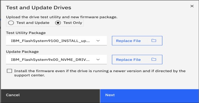
Figure 10-7 Drive firmware upgrade
3. Click Upgrade. Each drive upgrade takes approximately 6 minutes to complete.
4. You can also update individual drives by right-clicking a single drive and selecting Upgrade.
5. To monitor the progress of the upgrade, select Monitoring → Background Tasks.
Using the command line
To update the software on the system manually, complete these steps:
1. Copy the drive firmware package to the IBM FlashSystem by using the same method as described in Example 10-2 on page 462.
2. Issue the following CLI command to start the update process for all drives:
applydrivesoftware -file <software_update_file> -type firmware -all
where <software_update_file> is the filename of the software update file. The use of the -all option updates firmware on all eligible drives including quorum drives, which is a slight risk. To avoid this risk, use the -drive option instead and make sure the quorum is moved using the lsquorum and chquorum commands in between applydrivesoftware invocations.
|
Note: The maximum number of drive IDs that can be specified on a command line using the -drive option is 128. If you have more than 128 drives, use the -all option or run multiple invocations of applydrivesoftware to complete the update.
|
3. Issue the following CLI command to check the status of the update process:
lsdriveupgradeprogress
This command displays success when the update is complete.
4. To verify that the update has successfully completed, issue the lsdrive command for each drive in the system. The firmware_level field displays the new code level for each drive. Example 10-4 demonstrates how to list the firmware level for four specific drives:
Example 10-4 List firmware level for drives 0,1, 2 and 3
IBM_FlashSystem:GLTL-FS9K:superuser>for i in 0 1 2 3; do echo "Drive $i = `lsdrive $i|grep firmware`"; done
Drive 0 = firmware_level 1_2_11
Drive 1 = firmware_level 1_2_11
Drive 2 = firmware_level 1_2_11
Drive 3 = firmware_level 1_2_11
For more information, see this IBM Documentation web page.
10.7 Remote Code Load
Remote Code Load (RCL) is a service offering provided by IBM, which allows code updates to be performed by remote support engineers, as opposed to an onsite Support Services Representative (SSR).
IBM Assist on-site (AOS) or remote support center or Secure Remote Access (SRA) including Call Home enablement are required to enable Remote Code Load. With the Assist on-site enabled, the live remote-assistance tool, a member of IBM support team can view your desktop and share control of your mouse and keyboard to get you on your way to a solution. Rather than the RCL the tool can also speed up problem determination, collection of data, and ultimately, your problem solution.
For more information about configuring support assistance, see this IBM Documentation web page.
Before the Assist On-site application is used, you can test your connectivity to the Assist On-site network by downloading the IBM connectivity testing tool. For more information, see this IBM Support web page.
To request the RCL for your system, see this IBM Support web page and select your product type. Then, complete the following steps:
1. At the IBM Remote Code Load web page, select Product type → Book Now - FlashSystem 9200 and 7200 Remote Code Load.
Figure 10-8 shows the RCL Schedule Service page.

Figure 10-8 FlashSystem RCL Schedule Service page
2. Click Schedule Service to start scheduling the service.
3. Next is the Product type selection for RCL. Go to FlashSystem 9200 option and click Select (see Figure 10-9).

Figure 10-9 RCL Product type page
4. In the RCL time frame option, select the date (see Figure 10-10) and time frame (see Figure 10-11).

Figure 10-10 Time Frame selection page

Figure 10-11 RCL Time selection page
5. Enter your booking details in the RCL booking information form (see Figure 10-12).
Figure 10-12 RCL Booking information page
10.8 Replacing Flash Core Module
Replacing a Flash Core Module (FCM) in your IBM FlashSystem requires special attention to avoid out-of-scope procedures that can damage your system. Before you start the IBM FlashSystem FCM replacement procedure, review the following items to prevent any damage to your system and FCM or to your system data:
•Do not replace, re-seat, or run any task on your FlashSystem if you are not sure or not comfortable with the procedure, Always engage IBM support Level 1/2 in case of issues or any problem during any procedure you are running.
•Call IBM Support to ensure that the logs were verified and a correct action plan was provided to replace the failed FCM.
•Confirm with the IBM System Service Representative (SSR) if the correct FRU number was shipped to be replaced and that the action plan that was provided by IBM Support was revised.
•Confirm that your system does not have any other FCM failure or error messages in the error log tab before conducting the replacement procedure.
If you have the IBM Expert Care coverage feature for your FlashSystem, make sure that your Technical Account Manager (TAM) is aware of the procedure and engaged with the service team to proceed with the replacement.
For more information, see this IBM Documentation web page.
|
Note: Re-seating an FCM can reformat the module in specific instances. All FCM drive failure alerts must be addressed before any re-seat or replacement procedure is done. Upon receiving any error message for the FCM drives, it is recommended to escalate the problem to IBM Support.
|
10.9 SAN modifications
When you administer shared storage environments, human error can occur when a failure is fixed, or a change is made that affects one or more servers or applications. That error can then affect other servers or applications because suitable precautions were not taken.
Human error can include some the following examples:
•Disrupting or disabling the working disk paths of a server while trying to fix failed ones.
•Disrupting a neighbor SAN switch port while inserting or removing an FC cable or small form-factor pluggable (SFP).
•Disabling or removing the working part in a redundant set instead of the failed one.
•Making modifications that affect both parts of a redundant set without an interval that allows for automatic failover during unexpected problems.
Adhere to the following guidelines to perform these actions with assurance:
•Uniquely and correctly identify the components of your SAN.
•Use the proper failover commands to disable only the failed parts.
•Understand which modifications are necessarily disruptive, and which can be performed online with little or no performance degradation.
10.9.1 Cross-referencing WWPN
With the WWPN of an HBA, you can uniquely identify one server in the SAN. If the name of the server is changed at the operating system level and not at the IBM FlashSystem host definitions, it continues to access its mapped volumes exactly because the WWPN of the HBA did not change.
Alternatively, if the HBA of a server is removed and installed in a second server and the SAN zones for the first server and the IBM FlashSystem host definitions are not updated, the second server can access volumes that it probably should not access.
Complete the following steps to cross-reference HBA WWPNs:
1. In your server, verify the WWPNs of the HBAs that are used for disk access. Typically, you can complete this task by using the SAN disk multipath software of your server.
If you are using SDDPCM, run the pcmpath query WWPN command to see output similar to what is shown in Example 10-5.
Example 10-5 Output of the pcmpath query WWPN command
[root@Server127]> pcmpath query wwpn
Adapter Name PortWWN
fscsi0 10000090FA021A13
fscsi1 10000090FA021A12
If you are using server virtualization, verify the World Wide Port Names (WWPNs) in the server that is attached to the SAN, such as AIX Virtual Input/Output (VIO) or VMware ESX. Cross-reference with the output of the IBM FlashSystem lshost <hostname> command, as shown in Example 10-6 on page 473.
Example 10-6 Output of the lshost <hostname> command
IBM_FlashSystem:IBM Redbook FS:superuser>svcinfo lshost Server127
id 0
name Server127
port_count 2
type generic
mask 1111111111111111111111111111111111111111111111111111111111111111
iogrp_count 4
status active
site_id
site_name
host_cluster_id
host_cluster_name
protocol scsi
WWPN 10000090FA021A13
node_logged_in_count 1
state active
WWPN 10000090FA021A12
node_logged_in_count 1
state active
2. If necessary, cross-reference information with your SAN switches, as shown in Example 10-7. In Brocade switches use the nodefind <WWPN> command.
Example 10-7 Cross-referencing information with SAN switches
blg32sw1_B64:admin> nodefind 10:00:00:90:FA:02:1A:13
Local:
Type Pid COS PortName NodeName SCR
N 401000; 2,3;10:00:00:90:FA:02:1A:13;20:00:00:90:FA:02:1A:13; 3
Fabric Port Name: 20:10:00:05:1e:04:16:a9
Permanent Port Name: 10:00:00:90:FA:02:1A:13
Device type: Physical Unknown(initiator/target)
Port Index: 16
Share Area: No
Device Shared in Other AD: No
Redirect: No
Partial: No
Aliases: nybixtdb02_fcs0
b32sw1_B64:admin>
For storage allocation requests that are submitted by the server support team or application support team to the storage administration team, always include the server’s HBA WWPNs to which the new LUNs or volumes are supposed to be mapped. For example, a server might use separate HBAs for disk and tape access or distribute its mapped LUNs across different Has for performance. You cannot assume that any new volume is supposed to be mapped to every WWPN that server logged in the SAN.
If your organization uses a change management tracking tool, perform all your SAN storage allocations under approved change requests with the servers’ WWPNs that are listed in the Description and Implementation sections.
10.9.2 Cross-referencing LUN ID
Always cross-reference the IBM FlashSystem vdisk_UID with the server logical unit number (LUN) ID before you perform any modifications that involve IBM FlashSystem volumes. Example 10-8 shows an AIX server that is running Subsystem Device Driver Path Control Module (SDDPCM). The IBM FlashSystem vdisk_name has no relation to the AIX device name. Also, the first SAN LUN mapped to the server (SCSI_id=0) shows up as hdisk4 in the server because it had four internal disks (hdisk0 - hdisk3).
Example 10-8 Results of running the lshostvdiskmap command
IBM_FlashSystem:IBM Redbook FS:superuser>lshostvdiskmap NYBIXTDB03
id name SCSI_id vdisk_id vdisk_name vdisk_UID
0 NYBIXTDB03 0 0 NYBIXTDB03_T01 60050768018205E12000000000000000
root@nybixtdb03::/> pcmpath query device
Total Dual Active and Active/Asymmetric Devices : 1
DEV#: 4 DEVICE NAME: hdisk4 TYPE: 2145 ALGORITHM: Load Balance
SERIAL: 60050768018205E12000000000000000
==========================================================================
Path# Adapter/Path Name State Mode Select Errors
0* fscsi0/path0 OPEN NORMAL 7 0
1 fscsi0/path1 OPEN NORMAL 5597 0
2* fscsi2/path2 OPEN NORMAL 8 0
3 fscsi2/path3 OPEN NORMAL 5890 0
If your organization uses a change management tracking tool, include the vdisk_UID and LUN ID information in every change request that performs SAN storage allocation or reclaim.
|
Note: Because a host can have many volumes with the same scsi_id, always cross-reference the IBM FlashSystem volume UID with the host volume UID and record the scsi_id and LUN ID of that volume.
|
10.10 Server HBA replacement
Replacing a failed HBA in a server is a fairly trivial and safe operation if it is performed correctly. However, more precautions are required if your server has multiple, redundant HBAs on different SAN fabrics and the server hardware permits you to “hot” replace it (with the server still running).
Complete the following steps to replace a failed HBA and retain the working HBA:
1. In your server, identify the failed HBA and record its WWPNs. (For more information, see 10.9.1, “Cross-referencing WWPN” on page 472.) Then, place this HBA and its associated paths offline (gracefully if possible). This approach is important so that the multipath software stops attempting to recover it. Your server might even show a degraded performance while you perform this task.
2. Some HBAs have an external label that shows the WWPNs. If you have this type of label, record the WWPNs before you install the new HBA in the server.
3. If your server does not support HBA hot-swap, power off your system, replace the HBA, connect the used FC cable into the new HBA, and power on the system.
If your server does support hot-swap, follow the appropriate procedures to perform a “hot” replace of the HBA. Do not disable or disrupt the working HBA in the process.
4. Verify that the new HBA successfully logged in to the SAN switch. If it logged in successfully, you can see its WWPNs logged in to the SAN switch port. Otherwise, fix this issue before you continue to the next step.
Cross-check the WWPNs that you see in the SAN switch with the one you noted in step 1, and make sure that you did not record the wrong WWNN.
5. In your SAN zoning configuration tool, replace the old HBA WWPNs for the new ones in every alias and zone to which they belong. Do not touch the other SAN fabric (the one with the working HBA) while you perform this task.
Only one alias should use each WWPN, and zones must reference this alias.
If you are using SAN port zoning (though you should not be) and you did not move the new HBA FC cable to another SAN switch port, you do not need to reconfigure zoning.
6. Verify that the new HBA’s WWPNs appear in the IBM FlashSystem by using the lsfcportcandidate command.
If the WWPNs of the new HBA do not appear, troubleshoot your SAN connections and zoning.
7. Add the WWPNs of this new HBA in the IBM FlashSystem host definition by using the addhostport command. It is important that you do not remove the old one yet. Run the lshost <servername> command. Then, verify that the working HBA shows as active, while the failed HBA should show as inactive or offline.
8. Use software to recognize the new HBA and its associated SAN disk paths. Certify that all SAN LUNs have redundant disk paths through the working HBA and the new HBA.
9. Return to the IBM FlashSystem and verify again (by using the lshost <servername> command) that both the working and the new HBA’s WWPNs are active. In this case, you can remove the old HBA WWPNs from the host definition by using the rmhostport command.
10. Do not remove any HBA WWPNs from the host definition until you ensure that you have at least two active ones that are working correctly.
By following these steps, you avoid removing your only working HBA by mistake.
10.11 Hardware upgrades
The IBM FlashSystem scalability features allow significant flexibility in its configuration. As discussed in previous chapters, the IBM FlashSystem family has two different types of enclosures: control enclosures and expansion enclosures.
•Control Enclosures manage your storage systems, communicate with the host, and manage interfaces. In addition, they can also house up to 24 NVMe-capable flash drives.
•Expansion Enclosures increase the available capacity of an IBM FlashSystem cluster. They communicate with the control enclosure through a dual pair of 12 Gbps serial-attached SCSI (SAS) connections. These expansion enclosures can house many of flash (solid-state drive (SSD)) SAS type drives,
A basic configuration of an IBM FlashSystem storage platform consists of one IBM FlashSystem control enclosure. For a balanced increase of performance and scale, up to four (depending on model) IBM FlashSystem control enclosures can be clustered into a single storage system. Similarly, to increase capacity, up to two chains (depending on model) of expansion enclosures can be added per control enclosure. Therefore, several scenarios are possible for its growth.
These processes are described next.
10.11.1 Adding control enclosures
If your IBM FlashSystem cluster is below the maximum I/O groups limit for your specific product and you intend to upgrade it, you can install another control enclosure. It is also feasible that you might have a cluster of IBM Storwize V7000 nodes that you want to add the IBM FlashSystem enclosures to because the latter are more powerful than your existing ones. Therefore, your cluster can include different node models in different I/O groups.
To install these control enclosures, determine whether you need to upgrade your IBM FlashSystem first (or Storwize V7000 code level if you are merging an existing Storwize V7000 Gen2 cluster with a IBM FlashSystem 9200 for example).
For more information, see 10.5.2, “Hardware considerations” on page 458.
|
Note: If exactly two control enclosures are in a system, you must set up a quorum disk or application outside of the system. If the two control enclosures lose communication with each other, the quorum disk prevents both I/O groups from going offline.
|
IBM FlashSystem 9200
To add a control enclosure to an existing FlashSystem 9200 system, the IBM SSR engineer must first install the new control enclosure in the rack and cable it to SAN or Ethernet switches or directly to the existing control enclosure. You are then able to add it to the system using the management GUI where it should automatically appear if cabled correctly. For more information, see this IBM Documentation web page.
IBM FlashSystem 9100
To add a control enclosure to an existing FlashSystem 9100 system, the IBM SSR engineer must first install the new control enclosure in the rack and cable it to SAN or Ethernet switches or directly to the existing control enclosure. You are then able to add it to the system using the management GUI where it should automatically appear if cabled correctly. For more information, see this IBM Documentation web page.
IBM FlashSystem 7200
To add a control enclosure to an existing FlashSystem 7200 system, you must first install it in the rack. Then, you must connect it to the system through a zone in the SAN or by using RDMA over Ethernet. Finally, you can add it to the system using the management GUI where it should automatically appear if cabled correctly. For more information, see this IBM Documentation web page.
IBM FlashSystem 5x00
To add a control enclosure to an existing FlashSystem 5100 system, you must first install it in the rack. Then, you must connect it to the system through a zone in the SAN or by using RDMA over Ethernet. Finally, you can add it to the system using the management GUI where it should automatically appear if cabled correctly. For more information, see this IBM Documentation web page.
After you install the new nodes, you might need to redistribute your servers across the I/O groups. Consider the following points:
•Moving a server’s volume to different I/O groups can be done online because of a feature called Non-Disruptive Volume Movement (NDVM). Although this process can be done without stopping the host, careful planning and preparation is advised. For more information about supported operating systems, see this IBM Documentation web page.
|
Note: You cannot move a volume that is in a type of Remote Copy relationship.
|
•If each of your servers is zoned to only one I/O group, modify your SAN zoning configuration as you move its volumes to another I/O group. As best you can, balance the distribution of your servers across I/O groups according to I/O workload.
•Use the -iogrp parameter in the mkhost command to define which I/O groups of the IBM FlashSystem that the new servers use. Otherwise, IBM FlashSystem maps by default the host to all I/O groups, even if they do not exist and regardless of your zoning configuration.
Example 10-9 shows this scenario and how to resolve it by using the rmhostiogrp and addhostiogrp commands.
Example 10-9 Mapping the host to I/O groups
IBM_FlashSystem:IBM Redbook FS:superuser>lshost
id name port_count iogrp_count status site_id site_name host_cluster_id host_cluster_name protocol
0 Win2012srv1 2 4 online scsi
1 linuxsrv3 1 4 online scsi
IBM_FlashSystem:IBM Redbook FS:superuser>lshost Win2012srv1
id 0
name Win2012srv1
port_count 2
type generic
mask 1111111111111111111111111111111111111111111111111111111111111111
iogrp_count 4
status online
site_id
site_name
host_cluster_id
host_cluster_name
protocol scsi
WWPN 10000090FAB386A3
node_logged_in_count 2
state inactive
WWPN 10000090FAB386A2
node_logged_in_count 2
state inactive
IBM_FlashSystem:IBM Redbook FS:superuser>lsiogrp
id name node_count vdisk_count host_count site_id site_name
0 io_grp0 2 11 2
1 io_grp1 0 0 2
2 io_grp2 0 0 2
3 io_grp3 0 0 2
4 recovery_io_grp 0 0 0
?IBM_FlashSystem:IBM Redbook FS:superuser>lshostiogrp Win2012srv1
id name
0 io_grp0
1 io_grp1
2 io_grp2
3 io_grp3
IBM_FlashSystem:IBM Redbook FS:superuser>rmhostiogrp -iogrp 3 Win2012srv1
IBM_FlashSystem:IBM Redbook FS:superuser>
IBM_FlashSystem:IBM Redbook FS:superuser>lshostiogrp Win2012srv1
id name
0 io_grp0
1 io_grp1
2 io_grp2
IBM_FlashSystem:IBM Redbook FS:superuser>
IBM_FlashSystem:IBM Redbook FS:superuser>addhostiogrp -iogrp io_grp3 Win2012srv1
IBM_FlashSystem:IBM Redbook FS:superuser>
IBM_FlashSystem:IBM Redbook FS:superuser>lshostiogrp Win2012srv1
id name
0 io_grp0
1 io_grp1
2 io_grp2
3 io_grp3
IBM_FlashSystem:IBM Redbook FS:superuser>lsiogrp
id name node_count vdisk_count host_count site_id site_name
0 io_grp0 2 11 2
1 io_grp1 0 0 2
2 io_grp2 0 0 2
3 io_grp3 0 0 2
4 recovery_io_grp 0 0 0
•If possible, avoid setting a server to use volumes from different I/O groups that have different node types for extended periods of time. Otherwise, as this server’s storage capacity grows, you might experience a performance difference between volumes from different I/O groups. This mismatch makes it difficult to identify and resolve eventual performance problems.
10.11.2 Upgrading nodes in an existing cluster
If you want to upgrade the nodes or canisters of your existing IBM FlashSystem, there is the option to increase the cache memory size or the adapters in each node. This can be done, one node at a time, and so as to be nondisruptive to the systems operations. For more information, see this IBM Documentation web page.
When evaluating cache memory upgrades, consider the following points:
•As your working set and total capacity increases, you should consider increasing your cache memory size. A working set is the most accessed workloads, excluding snapshots and backups. Total capacity implies more or larger workloads and a larger working set.
•If you are consolidating from multiple controllers, consider at least matching the amount of cache memory across those controllers.
•When externally virtualizing controllers (such as switched virtual circuit), a large cache can accelerate older controllers with smaller caches.
•If you are using DRP, then maximize the cache size and consider adding SCM drives with Easy Tier for the best performance.
•If you are making heavy use of copy services, consider increasing the cache beyond just your working set requirements.
•A truly random working set might not benefit greatly from the cache.
|
Important: Do not power on a node that is shown as offline in the management GUI, if you powered off the node to add memory to increase total memory. Before you increase memory, you must remove a node from the system so that it is not showing in the management GUI or in the output from the svcinfo lsnode command.
Do not power on a node that is still in the system and showing as offline with more memory than the node had when it powered off. Such a node can cause an immediate outage or an outage when you update the system software.
|
When evaluating adapter upgrades, consider the following points:
•A single 32 Gb Fibre Channel port can deliver over 3 GBps (allowing for overheads).
•A 32 Gb FC card in each canister, with 8 ports can deliver more than 24 GBps.
•An FCM NVMe device can perform at over 1 GBps.
•A single 32 Gb Fibre Channel port can deliver 80,000 to 125,000 IOPS with a 4k block size.
•A 32 Gb FC card in each canister, with 8 ports can deliver up to 1,000,000 IOPS.
•A FlashSystem 9200 can deliver 1,200,000 4k read miss input/output operations per second (IOPS) and up to 4,500,000 4k read hit IOPS.
•If you have more than 12 NVMe devices, consider 2 Fibre Channel cards per canister. A third Fibre Channel card allows you to achieve up to 45 GBps.
•If you want to achieve more than 800,000 IOPS, use at least 2 Fibre Channel cards per canister.
•If the FlashSystem is performing Remote Copy or clustering, consider using separate ports to ensure that there is no conflict with host traffic.
•iSER by way of 25 GbE ports has similar capabilities as 16 Gb FC ports, but with less overall ports available. If you are planning on using 10 Gb iSCSI, ensure it can service your expected workloads.
Real-time performance statistics are available in the management GUI from the Monitoring → Performance menu, as shown in Figure 10-13.

Figure 10-13 IBM FlashSystem performance statistics (IOPS)
Memory options for an IBM FlashSystem 9200 control enclosure
A CPU processor has six memory channels, which are labeled A-F. Each memory channel has two dual inline memory module (DIMM) slots, numbered 0-1. For example, DIMM slots A0 and A1 are in memory channel A.
On the system board, the DIMM slots are labeled according to their memory channel and slot. They are associated with the CPU nearest to their DIMM slots. You can install three distinct memory configurations in those 24 DIMM slots in each node canister.
|
Important: The memory in both node canisters must be configured identically to create the total enclosure memory size
|
Table 10-2 shows the available memory configuration for each FlashSystem 9200 control enclosure. Each column gives the valid configuration for each total enclosure memory size. DIMM slots are listed in the same order that they appear in the node canister.
To ensure proper cooling and a steady flow of air from the fan modules in each node canister, blank DIMMs must be inserted in any slot that does not contain a memory module.
Table 10-2 Available memory configuration for one node in a control enclosure
|
DIMM Slot
|
Total enclosure memory 256 GB
|
Total enclosure memory 768 GB
|
Total enclosure memory 1536 GB
|
|
F0 (CPU0)
|
Blank
|
32 GB
|
32 GB
|
|
F1 (CPU0)
|
Blank
|
Blank
|
32 GB
|
|
E0 (CPU0)
|
Blank
|
32 GB
|
32 GB
|
|
E1 (CPU0)
|
Blank
|
Blank
|
32 GB
|
|
D0 (CPU0)
|
32 GB
|
32 GB
|
32 GB
|
|
D1 (CPU0)
|
Blank
|
Blank
|
32 GB
|
|
A1 (CPU0)
|
Blank
|
Blank
|
32 GB
|
|
A0 (CPU0)
|
32 GB
|
32 GB
|
32 GB
|
|
B1 (CPU0)
|
Blank
|
Blank
|
32 GB
|
|
B0 (CPU0)
|
Blank
|
32 GB
|
32 GB
|
|
C1 (CPU0)
|
Blank
|
Blank
|
32 GB
|
|
C0 (CPU0)
|
Blank
|
32 GB
|
32 GB
|
|
C0 (CPU1)
|
Blank
|
32 GB
|
32 GB
|
|
C1 (CPU1)
|
Blank
|
Blank
|
32 GB
|
|
B0 (CPU1)
|
Blank
|
32 GB
|
32 GB
|
|
B1 (CPU1)
|
Blank
|
Blank
|
32 GB
|
|
A0 (CPU1)
|
32 GB
|
32 GB
|
32 GB
|
|
A1 (CPU1)
|
Blank
|
Blank
|
32 GB
|
|
D1 (CPU1)
|
Blank
|
Blank
|
32 GB
|
|
D0 (CPU1)
|
32 GB
|
32 GB
|
32 GB
|
|
E1 (CPU1)
|
Blank
|
Blank
|
32 GB
|
|
E0 (CPU1)
|
Blank
|
32 GB
|
32 GB
|
|
F1 (CPU1)
|
Blank
|
Blank
|
32 GB
|
|
F0 (CPU1)
|
Blank
|
32 GB
|
32 GB
|
Memory options for an IBM FlashSystem 9100 control enclosure
Each of the six memory channels in each CPU has two DIMM slots, for a total of 12 DIMM slots per CPU, which means 24 DIMM slots per node canister and 48 DIMM slots per enclosure. You can install six distinct memory configurations in those 24 DIMM slots in each node canister. (Each canister must have the same amount of memory and the same configuration).
Initially, each control enclosure ships with one of the following features, depending on what has been ordered, as shown in Table 10-3.
Table 10-3 Base memory features
|
Feature
|
Memory per enclosure
|
Maximum per enclosure
|
|
ACG0
|
128 GB base cache memory (eight 16 GB DIMMs - 2 per CPU)
|
1
|
|
ACG1
|
768 GB base cache memory (twenty-four 32 GB DIMMs - 6 per CPU)
|
1
|
You can order the features that are listed in Table 10-4 to upgrade to more memory at any time.
Table 10-4 Memory features
|
Feature
|
Memory per enclosure
|
Maximum per enclosure
|
|
ACGA
|
128 GB memory upgrade (eight 16 GB DIMMs)
|
3
|
|
ACGB
|
768 GB memory upgrade (twenty-four 32 GB DIMMs)
|
2
|
Memory options for an IBM FlashSystem 7200 control enclosure
Table 10-5 lists the various memory options available for the IBM FlashSystem 7200 by feature code.
Table 10-5 IBM FlashSystem 7200 memory options
|
Base memory (GB)
|
Field Upgrade
ACGJ (GB) |
Field Upgrade
ACGB (GB) |
Total memory (GB)
|
|
256
|
N/A
|
N/A
|
256
|
|
256
|
512
|
N/A
|
768
|
|
256
|
512
|
768
|
1536
|
Memory options for an IBM FlashSystem 5000 control enclosure
The IBM FlashSystem 5000 family consists of different models, and each model type provides a different set of features. Table 10-6 lists the memory features of the FlashSystem 5000 and 5100 models.
Table 10-6 Memory options
|
Platform
|
FS5010
|
FS5015
|
FS5030
|
FS5035
|
FS5100
|
|
Option 1 per node
|
1 x 8 GB
|
1 x 16 GB
|
1 x 16 GB
|
1 x 16 GB
|
2 x 16 GB
|
|
Option 2 per node
|
1 x 16 GB
|
2 x 16 GB
|
2 x 16 GB
|
2 x 16 GB
|
6 x 16 GB
|
|
Option 3 per node
|
2 x 16 GB
|
N/A
|
N/A
|
N/A
|
6 x 16 GB +
6 x 32 GB
|
|
Maximum per I/O Group
|
64 GB
|
64 GB
|
64 GB
|
64 GB
|
576 GB
|
Memory options for an IBM FlashSystem 5200 control enclosure
Table 10-7 lists the FlashSystem 5200 memory options.
Table 10-7 FS 5200 memory options
|
Feature code
|
Existing
memory size per
canister (GB)
|
Memory
upgrade (GB)
|
Total memory
per enclosure
(GB)
|
Comments
|
|
ALG0
|
32 GB
|
N/A
|
64 GB
|
Ships two 32 GB DIMMs (DDR4)
that are installed with the base
system
|
|
ALG1
|
256 GB
|
N/A
|
512 GB
|
Ships eight 64 GB memory DIMMS
(DDR4) that are installed with the
base system
|
|
ALGC
|
32 GB
|
192 GB Cache Upgrade
|
256 GB
|
Ships six 32 GB memory DIMMS to
add to the system
|
|
ALGD
|
32 GB
|
512 GB Cache Upgrade
|
512 GB
|
Ships eight 64 GB memory DIMMS
to replace all existing 32 GB DIMMS
|
Adapter options for an IBM FlashSystem 9200 control enclosure
You can also add new adapters to the IBM FlashSystem 9200 nodes. These adapters are added as a pair (one card in each node). Six PCIe slots are available for port expansions in the IBM FlashSystem 9200 control enclosure. Each canister has three PCIe adapter slots and both canisters must have the same configuration. The PCIe adapter feature codes offer a pair of adapters to ensure that they are supplied symmetrically in each canister.
The control enclosure can be configured with three I/O adapter features to provide up to 24 16 Gb FC ports or up to 12 25 Gb Ethernet (iSCSI or iSCSI Extensions for Remote Direct Memory Access (RDMA) (iSER) capable) ports. The control enclosure also includes eight 10 Gb Ethernet ports as standard for iSCSI connectivity and two 1 Gb Ethernet ports for system management. A feature code also is available to include the SAS Expansion card if the user wants to use optional expansion enclosures. The options for the features available are shown in Table 10-8.
Table 10-8 IBM FlashSystem 9200 control enclosure adapter options
|
Number of control enclosures
|
16 Gbps/
32 Gbps FC |
On-board ISCSI
|
25 Gbps iSCSI (RoCE)
|
25 Gbps iSCSI (iWARP)
|
|
1
|
24
|
8
|
12
|
12
|
|
2
|
48
|
16
|
24
|
24
|
|
3
|
72
|
24
|
36
|
36
|
|
4
|
96
|
32
|
48
|
48
|
For more information about the feature codes, memory options, and functions of each adapter, see IBM FlashSystem 9200 Product Guide, REDP-5586.
Adapter options for an IBM FlashSystem 9100 control enclosure
You can also add new adapters to the IBM FlashSystem 9100 nodes. These adapters are added as a pair (one card in each node) and the options for the features available are shown in Table 10-9.
Table 10-9 IBM FlashSystem 9100 control enclosure adapter options
|
Number of cards
|
Ports
|
Protocol
|
Possible slots
|
Comments
|
|
0 - 3
|
4
|
16 Gb Fibre Channel
|
1, 2, 3
|
|
|
0 - 3
|
2
|
25 Gb Ethernet (iWarp)
|
1, 2, 3
|
|
|
0 - 3
|
2
|
25 Gb Ethernet (RoCE)
|
1, 2, 3
|
|
|
0 - 1
|
2 - see comment
|
12 Gb SAS Expansion
|
1, 2, 3
|
Card is 4 port with only 2 ports active (ports 1 and 3)
|
For more information about the feature codes, memory options, and functions of each adapter ca, see Planning chapter of IBM FlashSystem 9100 Architecture, Performance, and Implementation, SG24-8425.
Adapter options for an IBM FlashSystem 7200 control enclosure
Six PCIe slots are available for port expansions in the IBM FlashSystem 7200 control enclosure. Each canister has three PCIe adapter slots and both canisters must have the same configuration. The PCIe adapter feature codes offer a pair of adapters to ensure that they are supplied symmetrically in each canister.
The IBM FlashSystem 7200 control enclosure can be configured with three I/O adapter features to provide up to twenty-four 16 Gb FC ports or up to twelve 25 Gb Ethernet (iSCSI or iSER-capable) ports. The control enclosure also includes eight 10 Gb Ethernet ports as standard for iSCSI connectivity and two 1 Gb Ethernet ports for system management. A feature code also is available to include the SAS Expansion adapter if the user wants to implement the optional expansion enclosures.
Adapter options for an IBM FlashSystem 5x00 control enclosure
All of the FlashSystem 5000 control enclosures include 1 Gb Ethernet (GbE) or 10 GbE ports as standard for iSCSI connectivity. The standard connectivity can be extended with extra ports or enhanced with more connectivity through an optional I/O adapter feature. Table 10-10 lists which configurations are available for the FlashSystem 5000 and 5100.
Table 10-10 IBM FlashSystem 5000 family configurations
|
Platform
|
FS5010
|
FS5030
|
FS5100
|
|
iSCSI
|
1 x 1 GbE tech port + iSCSI
1 x 1 GbE iSCSI only
|
1 x 1 GbE dedicated tech port
|
1 x 1 GbE dedicated tech port
|
|
iSCSI
|
N/A
|
2 x 10 GbE (iSCSI only)
|
4 x 10 GbE (iSCSI only)
|
|
SAS
|
1 x 12 Gb SAS expansion
|
2 x 12 Gb SAS expansion
|
N/A
|
Table 10-11 lists the possible adapter installation for the FlashSystem 5000 and 5100. Only one interface card can be installed per canister and the interface card must be the same in both canisters.
Table 10-11 IBM FlashSystem 5000 family adapters
|
Platform
|
FS5010
|
FS5030
|
FS5100
|
|
FC
|
4-port 16 Gb Fibre Channel or
|
4-port 16 Gb Fibre Channel or
|
4-port 16 Gb Fibre Channel, FC NVMeoF or
|
|
iSCSI
|
4-port 10 GbE iSCSI or
|
4-port 10 GbE iSCSI or
|
2-port 25 GbE ROCE ISER, iSCSI or
|
|
iSCSI
|
2-port 25 GbE iSCSI or
|
2-port 25 GbE iSCSI or
|
2-port 25 GbE iWARP ISER, iSCSI and
|
|
SAS
|
4-port 12 Gb SAS host attach
|
4-port 12 Gb SAS host attach
|
2-port 12 Gb SAS to allow SAS expansions
|
IBM FlashSystem 5015 and 5035 control enclosures include 1 Gb Ethernet (GbE) or 10 GbE ports as standard for iSCSI connectivity. The standard connectivity can be extended by using more ports or enhanced with more connectivity through an optional I/O adapter feature. For more information, see this web page.
IBM FlashSystem 5015 control enclosure models 2N2 and 2N4
IBM FlashSystem 5015 control enclosure models 2N2 and 2N4 include the following features:
•Two node canisters, each with a two-core processor.
•32 GB cache (16 GB per canister) with optional 64 GB cache (32 GB per canister).
•1 Gb iSCSI connectivity standard with optional 16 Gb FC, 12 Gb SAS, 10 Gb iSCSI (optical), 25 Gb iSCSI (optical), and 1 Gb iSCSI connectivity.
•12 Gb SAS ports for expansion enclosure attachment.
•Twelve slots for 3.5-inch LFF SAS drives (Model 2N2) and 24 slots for 2.5-inch SFF SAS drives (Model 2N4).
•2U, 19-inch rack mount enclosure with 100 - 240 V AC or -48 V DC power supplies.
IBM FlashSystem 5035 control enclosure models 3N2 and 3N4
IBM FlashSystem 5035 control enclosure models 3N2 and 3N4 include the following features:
•Two node canisters, each with a six-core processor.
•32 GB cache (16 GB per canister) with optional 64 GB cache (32 GB per canister).
•10 Gb iSCSI (copper) connectivity standard with optional 16 Gb FC, 12 Gb SAS, 10 Gb iSCSI (optical), and 25 Gb iSCSI (optical) connectivity.
•12 Gb SAS ports for expansion enclosure attachment.
•Twelve slots for 3.5-inch LFF SAS drives (Model 3N2) and 24 slots for 2.5-inch SFF SAS drives (Model 3N4).
•2U, 19-inch rack mount enclosure with 100 - 240 V AC or -48 V DC power supplies.
IBM FlashSystem 5200 Host I/O connectivity and expansion enclosure adapters
Table 10-12 lists the maximum host count per control enclosure.
Table 10-12 Maximum host count per control enclosure
|
Number of control enclosures
|
16 Gb FC
|
32 Gb FC
|
On-board iSCSI
|
10 Gb Ethernet
|
25 Gb iSCSI
|
|
One enclosure
|
16
|
8
|
4
|
16
|
8
|
|
Two enclosures
|
32
|
16
|
8
|
32
|
16
|
|
Three enclosures
|
48
|
24
|
12
|
48
|
24
|
|
Four enclosures
|
64
|
32
|
16
|
64
|
32
|
IBM FlashSystem 5200 supported expansion enclosure and interface components
Table 10-13 lists the supported expansion enclosure MTMs 4662-6H2 and 4662-UH6.
Table 10-13 Supported expansion enclosure MTMs 4662-6H2 and 4662-UH6
|
Item
|
Feature code
|
Description
|
Ports
|
|
16 Gb FC 4 Port
Adapter Pair
|
#ALBJ
|
This feature provides two I/O
adapters. It is used to add
16 Gb FC connectivity.
|
Each adapter has four 16 Gb
FC ports and shortwave SFP
transceivers.
|
|
32 Gb FC 4 Port
Adapter Pair
|
#ALBK
|
This feature provides two I/O
adapters. It is used to add
32 Gb FC connectivity.
|
Each adapter has two 32 Gb
FC ports and shortwave SFP
transceivers.
|
|
10 Gb Ethernet
Adapter Pair
|
#ALBL
|
This feature provides two I/O
adapters. It is used to add
10 Gb Ethernet connectivity.
|
Each adapter has four 10 Gb
Ethernet ports and SFP+
transceivers.
|
|
25 GbE (RoCE)
Adapter Pair
|
#ALBM
|
This feature provides two I/O
adapters. It is used to add
25 Gb Ethernet connectivity.
Supports RoCE V2.
|
Each adapter has two 25 Gb
Ethernet ports and SFP28
transceivers.
|
|
25 GbE (iWARP)
Adapter Pair
|
#ALBN
|
This feature provides two I/O
adapters. It is used to add
25 Gb Ethernet connectivity.
Supports RDMA with iWARP.
|
Each adapter has two 25 Gb
Ethernet ports and SFP28
transceivers.
|
|
12 Gb SAS
expansion enclosure
Attach Card (Pair)
|
#ALBP
|
This feature provides two
4-port 12 Gb SAS expansion
enclosure attachment
adapters. This feature is used
to attach up to 20 expansion
enclosures.
|
Each adapter only has two
active SAS ports per card.
|
|
12 Gb SAS Host
Adapters (Pair)
|
#ALBQ
|
This feature provides two
4-port 12 Gb SAS Host
attachment adapters.
|
Two cards with 4 ports and
mini-SAS HD connectors for
host attachment.
|
|
16 Gb FC LW SFP
Transceivers (Pair)
|
#ACHU
|
This feature provides two
16 Gb longwave SFP
transceivers for use with 16 Gb
FC I/O ports.
|
#ALBJ is a prerequisite. The
maximum that is allowed is four for
each instance of #ALBJ.
|
|
32 Gb FC LW SFP
Transceivers (Pair)
|
#ACHV
|
This feature provides two
32 Gb longwave SFP
transceivers for use with 32 Gb
FC I/O ports.
|
#ALBK is a prerequisite. The
maximum that is allowed is four for
each instance of #ALBK.
|
10.11.3 Upgrading NVMe drives
To provide ultra-low latency for performance sensitive but less cache-friendly workloads, storage-class memory (SCM) drives from Intel and Samsung are available as a persistent storage tier for IBM FlashSystem family. SCM is a substantial step forward in memory technology, offering nonvolatile, ultra low latency memory for a fraction of the cost of traditional memory chips.
IBM FlashSystem products support SCM drives over NVMe to improve overall storage performance, or offer a higher performance storage pool. This means SCM drives can be used for small workloads that need exceptional levels of performance at the lowest latencies, or they can be combined with other NVMe drives using Easy Tier to accelerate much larger workloads. Like the FlashCore Modules, SCM drives are also available as upgrades for the previous generation of all flash arrays.
Spectrum Virtualize V8.4 supports up to 12 SCM drives in a control enclosure for IBM FlashSystem 9000, 7000, 5000, 5100 and 5200 families.
For more information, see the following resources:
10.11.4 Moving to a new IBM FlashSystem cluster
You might have a highly populated, intensively used IBM FlashSystem cluster that you want to upgrade. You might also want to use the opportunity to refresh your IBM FlashSystem and SAN storage environment.
Complete the following steps to replace your cluster entirely with a newer, more powerful one:
1. Install your new IBM FlashSystem cluster.
2. Create a replica of your data in your new cluster.
3. Migrate your servers to the new IBM FlashSystem cluster when convenient.
If your servers can tolerate a brief, scheduled outage to switch from one IBM FlashSystem cluster to another, you can use the IBM FlashSystem Remote Copy services (Metro Mirror or Global Mirror) to create your data replicas, following these steps:
1. Select a host that you want to move to the new IBM FlashSystem cluster and find all the old volumes you must move.
2. Zone your host to the new IBM FlashSystem cluster.
3. Create Remote Copy relationships from the old volumes in the old IBM FlashSystem cluster to new volumes in the new IBM FlashSystem cluster.
4. Map the new volumes from the new IBM FlashSystem cluster to the host.
5. Discover new volumes on the host.
6. Stop all I/O from the host to the old volumes from the old IBM FlashSystem cluster.
7. Disconnect and remove the old volumes on the host from the old IBM FlashSystem cluster.
8. Unmap the old volumes from the old IBM FlashSystem cluster to the host.
9. Make sure Remote Copy relationships between old and new volumes in the old and new IBM FlashSystem cluster are synced.
10. Stop and remove Remote Copy relationships between old and new volumes so that the target volumes in the new IBM FlashSystem cluster receive read/write access.
11. Import data from the new volumes and start your applications on the host.
If you must migrate a server online, instead, you must use host-based mirroring by completing the following steps:
1. Select a host that you want to move to the new IBM FlashSystem cluster and find all the old volumes that you must move.
2. Zone your host to the new IBM FlashSystem cluster.
3. Create volumes in the new IBM FlashSystem cluster of the same size as the old volumes in the old IBM FlashSystem cluster.
4. Map the new volumes from the new IBM FlashSystem cluster to the host.
5. Discover new volumes on the host.
6. For each old volume, use host-based mirroring (such as AIX mirrorvg) to move your data to the corresponding new volume.
7. For each old volume, after the mirroring is complete, remove the old volume from the mirroring group.
8. Disconnect and remove the old volumes on the host from the old IBM FlashSystem cluster.
9. Unmap the old volumes from the old IBM FlashSystem cluster to the host.
This approach uses the server’s computing resources (CPU, memory, and I/O) to replicate the data. It can be done online if properly planned. Before you begin, make sure it has enough spare resources.
The biggest benefit to using either approach is that they easily accommodate (if necessary) the replacement of your SAN switches or your back-end storage controllers. You can upgrade the capacity of your back-end storage controllers or replace them entirely, as you can replace your SAN switches with bigger or faster ones. However, you do need to have spare resources, such as floor space, power, cables, and storage capacity, available during the migration.
10.11.5 Splitting an IBM FlashSystem cluster
Splitting an IBM FlashSystem cluster might become a necessity if you have one or more of the following requirements:
•To grow the environment beyond the maximum number of I/O groups that a clustered system can support.
•To grow the environment beyond the maximum number of attachable subsystem storage controllers.
•To grow the environment beyond any other maximum system limit.
•To achieve new levels of data redundancy and availability.
By splitting the clustered system, you no longer have one IBM FlashSystem that handles all I/O operations, hosts, and subsystem storage attachments. The goal is to create a second IBM FlashSystem cluster so that you can equally distribute the workload over the two systems.
After safely removing enclosures from the existing cluster and creating a second IBM FlashSystem cluster, choose from the following approaches to balance the two systems:
•Attach new storage subsystems and hosts to the new system and start adding only new workload on the new system.
•Migrate the workload onto the new system by using the approach described in 10.11.4, “Moving to a new IBM FlashSystem cluster” on page 488.
10.11.6 Adding expansion enclosures
As time passes and your environment grows, you must add storage to your system. Depending on the IBM FlashSystem family product and the code level that you installed, you can add different numbers of expansion enclosures to your system. Before you add an enclosure to a system, check that the licensed functions of the system support the extra enclosure.
Because all IBM FlashSystem models were designed to make managing and maintaining them as simple as possible, adding an expansion enclosure is an easy task. For more information, see this IBM Documentation web page.
IBM FlashSystem 9200
Currently, IBM offers the following SAS expansion enclosures that can be attached to the IBM FlashSystem 9200. Each node can support 10 SAS Connections thus a control enclosure can support up to 20 expansion enclosures.
|
Note: To support SAS expansion enclosures, an AHBA - SAS Enclosure Attach adapter must be installed in each node canister of the IBM FlashSystem 9200 control enclosure.
|
The following types of expansion enclosures are available:
•IBM FlashSystem 9000 LFF Expansion Enclosure Model A9F
•IBM FlashSystem 9000 SFF Expansion Enclosure Model AFF
The new IBM FlashSystem 9200 SFF expansion enclosure Model AFF offers new tiering options with solid-state drive (SSD flash drives). Up to 480 drives of serial-attached SCSI (SAS) expansions are supported per IBM FlashSystem 9200 control enclosure. The expansion enclosure is 2U high.
The new IBM FlashSystem 9200 LFF expansion enclosure Model A9F offers new tiering options with solid-state drive (SSD flash drives). Up to 736 drives of serial-attached SCSI (SAS) expansions are supported per IBM FlashSystem 9200 control enclosure. The expansion enclosure is 5U high.
The best practice recommendation is to balance equally the expansion enclosures between chains. So, if you have two extra expansion enclosures one should be installed on the first SAS chain and one on the second SAS chain. In addition, when you add a single expansion enclosure to an existing system, it is preferable to add the enclosure directly below the control enclosure. When you add a second expansion enclosure, it is preferable to add the enclosure directly above the control enclosure. As more expansion enclosures are added, alternative adding them above and below.
The IBM FlashSystem 9200 system supports up to four control enclosures and up to two chains of SAS expansion enclosures per control enclosure. To limit contention for bandwidth on a chain of SAS enclosures, no more than 10 expansion enclosures can be chained to SAS port 1 of a node canister and no more than 10 expansion enclosures can be chained to SAS port 3 of a node canister. On each SAS chain, the systems can support up to a SAS chain weight of ten, where:
•Each 9846-A9F or 9848-A9F expansion enclosure adds a value of 2.5 to the SAS chain weight.
•Each 9846-AFF or 9848-AFF expansion enclosure adds a value of 1 to the SAS chain weight.
For example, each of the following expansion enclosure configurations has a total SAS weight of ten:
•Four 9848-A9F enclosures per SAS chain
•Two 9846-A9F enclosures and five 9848-AFF enclosures per SAS chain
Figure 10-14 shows the cabling for adding two A9F expansion enclosures and two AFF expansion enclosures to a single control enclosure (in the center of Figure 10-14).
For more information, see this IBM Documentation web page.

Figure 10-14 Cabling for adding four expansion enclosures in two SAS chains
Adding expansion enclosures is simplified because IBM FlashSystem 9200 can automatically discover new expansion enclosures after the SAS cables are connected. It is possible to manage and use the new drives without managing the new expansion enclosures. However, unmanaged expansion enclosures are not monitored properly. This issue can lead to more difficult troubleshooting and can make problem resolution take longer.
To avoid this situation, always manage newly added expansion enclosures and follow these guidelines:
•FlashSystem 9200 systems support 4-port SAS interface adapters. However, only ports 1 and 3 are used for SAS connections.
•Connect SAS port 1 of the upper node canister in the control enclosure to SAS port 1 of the left expansion canister in the first expansion enclosure.
•Connect SAS port 1 of the lower node canister in the control enclosure to SAS port 1 of the right expansion canister in the first expansion enclosure.
•In general, the SAS interface adapter must be installed in PCIe slot 3 of the node canister.
•No cable can be connected between a port on a left canister and a port on a right canister.
•A cable must not be connected between ports in the same enclosure.
•A connected port on the node canister must connect to a single port on an expansion canister. Cables that split the connector out into separate physical connections are not supported.
•Attach cables serially between enclosures; do not skip an enclosure.
•The last expansion enclosure in a chain must not have cables in port 2 of canister 1 or port 2 of canister 2.
•Ensure that cables are installed in an orderly way to reduce the risk of cable damage when replaceable units are removed or inserted.
IBM FlashSystem 9100
The procedure for adding expansion enclosures to an IBM FlashSystem 9100 control enclosure is similar to that described in section “IBM FlashSystem 9200” on page 490.
For more information, see this IBM Documentation web page.
IBM FlashSystem 7200
The following types of expansion enclosures are available:
•IBM FlashSystem 7200 LFF Expansion Enclosure Model 12G
•IBM FlashSystem 7200 SFF Expansion Enclosure Model 24G
•IBM FlashSystem 7200 Dense Expansion Enclosure Model 92G
When attaching expansion enclosures to the control enclosure, you are not limited by the type of the enclosure (if it meets all generation level restrictions). The only limitation for each SAS chain is its chain weight. Each type of enclosure defines its own chain weight, as follows:
•Enclosures 12G and 24G have a chain weight of 1.
•Enclosure 92G has a chain weight of 2.5.
•The maximum chain weight for any SAS chain is 10.
•The maximum number of SAS chains per control enclosure is 2.
For example, you can combine seven 24G and one 92G expansion enclosures (7x1 + 1x2.5 = 9.5 chain weight), or two 92G enclosures, one 12G, and four 24G (2x2.5 + 1x1 + 4x1 = 10 chain weight).
You can use either the addcontrolenclosure command or the Add Enclosure wizard in the management GUI to add the new expansion enclosure to the system.
To access the Add Enclosure wizard, select Monitoring → System Hardware. On the System Hardware - Overview page, select Add Enclosure to start the wizard. Complete the wizard and verify the new enclosure.
If Add Enclosure is not displayed, it indicates a potential cabling issue. Check the installation information to ensure that the enclosure was cabled correctly.
Complete the following steps to add an enclosure to the system by using the CLI:
1. Using the sainfo lsservicestatus command (on the service CLI of the new enclosure), record the WWNN of the new enclosure.
2. Record the serial number of the enclosure, which is needed in later steps.
3. Enter the following command to verify that the enclosure is detected on the fabric:
svcinfo lscontrolenclosurecandidate
4. Enter the lsiogrp command to determine the I/O group, where the enclosure must be added:
5. Record the name or ID of the first I/O group that has a node count of zero. You need the ID for the next step.
6. Enter the following command to add the enclosure to the system:
addcontrolenclosure -iogrp iogrp_name | iogrp_id -sernum enclosureserialnumber
where:
– iogrp_name | iogrp_id is the name or ID of the I/O group
– enclosureserialnumber is the serial number of the enclosure
7. Record this information for future reference:
– Serial number.
– Worldwide node name of both node canisters.
– All of the worldwide port names.
– The name or ID of the I/O group that contains the enclosure.
8. Enter the lsnodecanister command to verify that the node canisters in the enclosure are online.
For more information, see this IBM Documentation web page.
IBM FlashSystem 5x00
Similar to the IBM FlashSystem 7200, the following types of expansion enclosures are available for the 5x00 family:
•FlashSystem 5x00 family supports the attachment of FlashSystem 5x00 expansion enclosure models 12G, 24G, and 92G.
•IBM FlashSystem Model 12G (LFF) supports up to 12 3.5-inch drives.
•IBM FlashSystem Model 24G (SFF) supports up to 24 2.5-inch drives.
•IBM FlashSystem Model 92G holds 92 3.5-inch SAS drives.
High-performance disk drives, high-capacity nearline disk drives, and flash (solid state) drives are supported. Drives of the same form factor can be intermixed within an enclosure, and LFF and SFF expansion enclosures can be intermixed within a FlashSystem 5x00 system.
The IBM FlashSystem 5010 supports only one control enclosure and only one SAS expansion chain.
The IBM FlashSystem 5010 supports only one control enclosure and only one SAS expansion chain.
The procedure for adding expansion enclosures to an IBM FlashSystem 5x00 control enclosure is similar to that described in “IBM FlashSystem 7200” on page 492.
For more information, see this IBM Documentation web page.
10.11.7 Removing expansion enclosures
As storage environments change and grow it is sometimes necessary to move expansion enclosures between control enclosures. Removing an expansion enclosure is a straightforward task.
To remove an expansion enclosure from a control enclosure, complete the following steps:
1. If the expansion enclosure that you want to move is not at the end of a SAS chain, you might need a longer pair of SAS cables to complete the procedure. In that case, ensure that you have two SAS cables of suitable length before you start this procedure.
2. Delete any volumes that are no longer needed and that depend on the enclosure that you plan to remove.
3. Delete any remaining arrays that are formed from drives in the expansion enclosure. Any data in those arrays is automatically migrated to other managed disks in the pool if there is enough capacity.
4. Wait for data migration to complete.
5. Mark all the drives (including any configured as spare or candidate drives) in the enclosures to be removed as unused.
6. Unmanage and remove the expansion enclosure by using the management GUI. Select Monitoring → System Hardware. On the System Hardware - Overview page, select the directional arrow next to the enclosure that you are removing to open the Enclosure Details page. Select Enclosure Actions → Remove.
|
Important: Do not proceed until the enclosure removal process completes successfully.
|
7. On the I/O group that contains the expansion enclosure that you want to remove, enter the following command to put the I/O group into maintenance mode:
chiogrp -maintenance yes <iogroup_name_or_id>
8. If the expansion enclosure that you want to move is at the end of a SAS chain, complete the following steps to remove the enclosure from the SAS chain:
a. Disconnect the SAS cable from port 1 of canister 1 and canister 2. The enclosure is now disconnected from the system.
b. Disconnect the other ends of the SAS cables from the previous enclosure in the SAS chain. The previous enclosure is now the end of the SAS chain. Proceed to step 10.
9. If the expansion enclosure is not at the end of a SAS chain, complete the following steps to remove the enclosure from the SAS chain:
a. Disconnect the SAS cable from port 2 of canister 1 of the expansion enclosure that you want to move.
b. Disconnect the other end of the same SAS cable from port 1 of canister 1 of the next expansion enclosure in the SAS chain.
c. Disconnect the SAS cable from port 1 of canister 1 of the expansion enclosure that you want to move.
d. Reroute the cable that was disconnected in the previous step and connect it to port 1 of canister 1 of the next expansion enclosure in the SAS chain.
|
Important: Do not continue until you complete this cable connection step.
|
e. Disconnect the SAS cable from port 2 of canister 2 of the expansion enclosure that you want to move.
f. Disconnect the other end of the same SAS cable from port 1 of canister 2 of the next expansion enclosure in the SAS chain.
g. Disconnect the SAS cable from port 1 of canister 2 of the expansion enclosure that you want to move.
h. Reroute the cable that was disconnected in the previous step and connect it to port 1 of canister 2 of the next expansion enclosure in the SAS chain.
10. Take the I/O group out of maintenance mode by entering the following command:
chiogrp -maintenance no <iogroup_name_or_id>
11. Check the event log for any errors and fix those errors as needed.
12. Disconnect the power from the expansion enclosure that you want to remove.
13. Remove the expansion enclosure from the rack along with its two power cables and two SAS cables.
Note that the IBM FlashSystem products provide methods to securely erase data from a drive when an enclosure is decommissioned or before a drive is removed from the system during a repair activity.
For more information about the CLI commands that are used to run this secure erase function, see this IBM Documentation web page.
10.11.8 IBM FlashWatch
Driven by the concept of “Storage Made Simple,” IBM FlashWatch is a suite of programs that enhances your experience of owning IBM FlashSystem storage. Bringing together programs which span the acquisition, operation and migration phases, this suite aims to reduce deployment and operational risks to improve your support experience, and to offer a fully flexible, commitment-free hardware refresh. For more information, see What is IBM FlashWatch? Peace of Mind Made Simple.
IBM FlashWatch is an offering from IBM to complement the purchase of the IBM FlashSystem product. It provides the following features that are included in the purchase of the product:
•IBM Flash Momentum
Flash Momentum is a storage upgrade program which allows you to replace your controller and storage every 3 years with full flexibility. Before the expiration of the agreement period, you decide whether to keep your FlashSystem, refresh it or simply walk away. You can refresh your FlashSystem for the same monthly price or less, or upsize or downsize your system to meet your needs.
•High Availability guarantee
Robust Spectrum Virtualize software has a measured availability of 99.9999% and IBM offers an optional 100% availability commitment when HyperSwap is also used.
•Data Reduction Guarantee:
A 2:1 data reduction is ensured and you must self-certify that the data you are writing can be reduced (for example, not encrypted, not compressed). Up to 5:1 data reduction can be ensured with more detailed profiling of your workload.
•All-inclusive Licensing
All storage functions available are included in the licensing cost for internal storage.
•Comprehensive Care
Up to seven years of 24x7 support, with three years of IBM Technical Advisor support, enhanced response times of 30 minutes for severity 1 incidents, and six managed code upgrades over three years. However, this feature is not available for all IBM FlashSystem models (see Table 10-14).
•Storage Insights
Storage Insights is included at no extra cost to proactively manage your environment.
•Flash Endurance Guarantee
Flash media is covered for all workloads while under warranty or maintenance.
•IBM Storage Utility pricing
The IBM Storage Utility pricing solution delivers three years of your planned capacity needs on day one. To predict and control your future needs, IBM uses IBM Storage Insights to help you easily meet your capacity needs without interrupting your data center. The IBM FlashSystem 9200 (9848-UG8) is leased through IBM Global Finance on a three-year lease, which entitles the customer to use approximately 30 - 40% of the total system capacity at no extra cost. If storage needs to increase beyond that initial capacity, usage is billed on a quarterly basis based on the average daily provisioned capacity per terabyte per month.
•No Cost Migration
For a 90-day period, from the date of installation, you can migrate data from over 500 older storage systems (IBM and non-IBM) to your FlashSystem product using an approach of your choice, without having to pay any additional external licensing.
Table 10-14 provides a summary product matrix for IBM FlashSystem products.
Table 10-14 IBM FlashWatch product matrix for IBM FlashSystem products
|
IBM FlashWatch feature
|
FS5000
|
FS5200
|
FS7200
|
FS9200
|
FS9200R
|
|
High Availability guarantee
|
FS5035 only
|
Yes
|
Yes
|
Yes
|
Yes
|
|
Data reduction guarantee
|
FS5035 only
|
Yes
|
Yes
|
Yes
|
Yes
|
|
All-inclusive licensing (Excluding external virtualization, encryption)
|
N/A
|
Yes
|
Yes
|
Yes
|
Yes
|
|
Expert Care
|
Alternative optional
services available;
9x5 NBD warranty
|
Yes
(4662-6H2, UH6, 12G,
24G, 92G)
|
Yes
(4664-824, U7C, 12G,
24G, 92G)
|
Yes
(4666-AG8, UG8, AFF,
A9F)
|
Yes
(4666-AG8, UG8, AFF,
A9F)
|
|
Cloud analytics with
Storage Insights
|
Yes
|
Yes, with IBM Storage
Expert Care
|
Yes
|
Yes
|
Yes
|
|
Flash Endurance guarantee
|
Yes
|
Yes
|
Yes
|
Yes
|
Yes
|
|
IBM Flash momentum
Storage Upgrade Program
|
Yes
(2072-2N2, 2N4, 3N2,
3N4, 12G, 24G, 92G)
|
Yes
(4662-6H2, UH6,
12G, 24G, 92G)
|
Yes
(4664, 2076-824, U7C,
12G, 24G, 92G)
|
Yes
(4666, 9848-AG8, UG8,
AFF, A9F)
|
Yes
(4666, 9848-AG8)
|
|
Cloud-like pricing
(Storage Utility)
|
N/A
|
Yes
(4662-UH6)
|
Yes
(4664, 2076-U7C)
|
Yes
(4666, 9848-UG8)
|
N/A
|
|
No Cost Migration
|
Yes
|
Yes
|
Yes
|
Yes
|
Yes
|
For more information about the IBM FlashWatch offering, see IBM FlashWatch FAQ.
10.12 I/O throttling
I/O throttling is a mechanism that allows you to limit the volume of I/O processed by the storage controller at various levels to achieve quality of service (QoS). If a throttle is defined, the system either processes the I/O, or delays the processing of the I/O to free resources for more critical I/O. Throttling is a way to achieve a better distribution of storage controller resources.
IBM FlashSystem V8.3 and later code brings the possibility to set the throttling at a volume level, host, host cluster, storage pool, and offload throttling by using the GUI. This section describes some details of I/O throttling and shows how to configure the feature in your system.
10.12.1 General information about I/O throttling
I/O throttling features the following characteristics:
•IOPS and bandwidth throttle limits can be set.
•It is an upper bound QoS mechanism.
•No minimum performance is guaranteed.
•Volumes, hosts, host clusters, and managed disk groups can be throttled.
•Queuing occurs at microsecond granularity.
•Internal I/O operations (FlashCopy, cluster traffic, and so on) are not throttled.
•Reduces I/O bursts and smooths the I/O flow with variable delay in throttled I/Os.
•Throttle limit is a per node value.
10.12.2 I/O throttling on front-end I/O control
You can use throttling for a better front-end I/O control at the volume, host, host cluster, and offload levels:
•In a multi-tenant environment, hosts can have their own defined limits.
You can use this to allow restricted I/Os from a data mining server and a higher limit for an application server.
•An aggressive host consuming bandwidth of the controller can be limited by a throttle.
For example, a video streaming application can have a limit set to avoid consuming too much of the bandwidth.
•Restrict a group of hosts by their throttles.
For example, Department A gets more bandwidth than Department B.
•Each volume can have a defined throttle.
For example, a volume that is used for backups can be configured to use less bandwidth than a volume used for a production database.
•When performing migrations in a production environment consider using host or volume level throttles.
•Offloaded I/Os.
Offload commands, such as UNMAP and XCOPY, free hosts and speed the copy process by offloading the operations of certain types of hosts to a storage system. These commands are used by hosts to format new file systems or copy volumes without the host needing to read and then write data. Throttles can be used to delay processing for offloads to free bandwidth for other more critical operations, which can improve performance but limits the rate at which host features, such as VMware VMotion, can copy data.
10.12.3 I/O throttling on back-end I/O control
You can also use throttling to control the back-end I/O by throttling the storage pools, which can be useful in the following scenarios:
•Each storage pool can have a defined throttle.
•Allows control of back-end I/Os from the IBM FlashSystem.
•Useful to avoid overwhelming any external back-end storage.
•Useful in case of VVOLS since a VVOL gets created in a child pool. A child pool (mdiskgrp) throttle can control I/Os coming from that VVOL.
•Only parent pools support throttles because only parent pools contain MDisks from internal or external back-end storage. For volumes in child pools, the throttle of the parent pool is applied.
•If more than one throttle applies to an I/O operation, the lowest and most stringent throttle is used. For example, if a throttle of 100 MBps is defined on a pool and a throttle of 200 MBps is defined on a volume of that pool, the I/O operations are limited to 100 MBps.
10.12.4 Overall benefits of using I/O throttling
The overall benefit of the use of I/O throttling is a better distribution all system resources that includes the following benefits:
•Avoids overwhelming the controller objects.
•Avoids starving the external entities, like hosts, from their share of controller.
•Creates scheme of distribution of controller resources that, in turn, results in better utilization of external resources such as host capacities.
With throttling not enabled, a scenario exists in where Host1 dominates the bandwidth, and after enabling the throttle, a much better distribution of the bandwidth among the hosts results, as shown in Figure 10-15.

Figure 10-15 Distribution of controller resources before and after I/O throttling
10.12.5 Considerations for I/O throttling
Consider the following points when you are planning to use I/O throttling:
•The throttle cannot be defined for the host if it is part of a host cluster that has a host cluster throttle.
•If the host cluster does not have a throttle that is defined, its member hosts can have their individual host throttles defined.
•If a volume has multiple copies, then throttling would be done for the storage pool serving the primary copy. The throttling is not applicable on the secondary pool for mirrored volumes and stretched cluster implementations.
•A host cannot be added to a host cluster if both have their individual throttles defined. If just one of the host or host cluster throttles is present, the command succeeds.
•A seeding host that is used for creating a host cluster cannot have a host throttle that is defined for it.
|
Note: Throttling is only applicable at the I/Os that an IBM FlashSystem receives from hosts and host clusters. The I/Os generated internally, such as mirrored volume I/Os, cannot be throttled.
|
10.12.6 Configuring I/O throttling using the CLI
To create a throttle using the CLI, use the mkthrottle command, as shown in Example 10-10. The bandwidth limit is the maximum amount of bandwidth the system can process before the system delays I/O processing. Similarly, the iops_limit is the maximum amount of IOPS the system can process before the system delays I/O processing.
Example 10-10 Creating a throttle using the mkthrottle command in the CLI
Syntax:
mkthrottle -type [offload | vdisk | host | hostcluster | mdiskgrp]
[-bandwidth bandwidth_limit_in_mb]
[-iops iops_limit]
[-name throttle_name]
[-vdisk vdisk_id_or_name]
[-host host_id or name]
[-hostcluster hostcluster_id or name]
[-mdiskgrp mdiskgrp_id or name]
Usage examples:
IBM_FlashSystem:IBM Redbook FS:superuser>mkthrottle -type host -bandwidth 100 -host ITSO_HOST3
IBM_FlashSystem:IBM Redbook FS:superuser>mkthrottle -type host cluster -iops 30000 -hostcluster ITSO_HOSTCLUSTER1
IBM_FlashSystem:IBM Redbook FS:superuser>mkthrottle -type mdiskgrp -iops 40000 -mdiskgrp 0
IBM_FlashSystem:IBM Redbook FS:superuser>mkthrottle -type offload -bandwidth 50
IBM_FlashSystem:IBM Redbook FS:superuser>mkthrottle -type vdisk -bandwidth 25 -vdisk volume1
IBM_FlashSystem:IBM Redbook FS:superuser>lsthrottle
throttle_id throttle_name object_id object_name throttle_type IOPs_limit bandwidth_limit_MB
0 throttle0 2 ITSO_HOST3 host 100
1 throttle1 0 ITSO_HOSTCLUSTER1 host cluster 30000
2 throttle2 0 Pool0 mdiskgrp 40000
3 throttle3 offload 50
4 throttle4 10 volume1 vdisk 25
|
Note: You can change a throttle parameter by using the chthrottle command.
|
10.12.7 Configuring I/O throttling using the GUI
The following sections show how to configure the throttle by using the management GUI.
10.12.8 Creating a volume throttle
To create a volume throttle, go to Volumes → Volumes, then select the wanted volume, right-click it and chose Edit Throttle, as shown in Figure 10-16. The bandwidth can be set from 1 MBps - 256 TBps and IOPS can be set from 1 - 33,254,432.
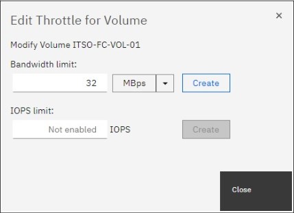
Figure 10-16 Creating a volume throttle in the GUI
If a throttle already exists, the dialog box that is shown in Figure 10-16 on page 501 also shows a Remove button that is used to delete the throttle.
10.12.9 Creating a host throttle
To create a host throttle, go to Hosts → Hosts, select the wanted host, then right-click it and chose Edit Throttle, as shown in Figure 10-17.
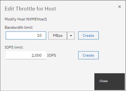
Figure 10-17 Creating a host throttle in the GUI
10.12.10 Creating a host cluster throttle
To create a host cluster throttle, go to Hosts → Host Clusters, select the wanted host cluster, then right-click it and chose Edit Throttle, as shown in Figure 10-18.

Figure 10-18 Creating a host cluster throttle in the GUI
10.12.11 Creating a storage pool throttle
To create a storage pool throttle, go to Pools → Pools, select the wanted storage pool, then right-click it and choose Edit Throttle, as shown in Figure 10-19.

Figure 10-19 Creating a storage pool throttle in the GUI
10.12.12 Creating an offload throttle
To create an offload throttle, go to Monitoring → System Hardware → Actions, then select Edit System Offload Throttle, as shown in Figure 10-20.
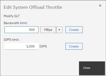
Figure 10-20 Creating system offload throttle in the GUI
10.13 Automation
Automation has become a priority for maintaining today’s busy storage environments. Automation software allows the creation of repeatable sets of instructions and processes to reduce the need for human interaction with computer systems. Red Hat Ansible and other third-party automation tools are becoming increasingly used across the enterprise IT environments and it is not unexpected that their use in storage environments is becoming more popular.
10.13.1 Red Hat Ansible
IBM FlashSystem family includes integration with Red Hat Ansible Automation Platform, allowing IT to create an Ansible playbook that automates repetitive tasks across an organization in a consistent way, helping improve outcomes and reduce errors.
Ansible is an agentless automation management tool that uses the SSH protocol. Currently, Ansible can be run from any machine with Python 2 (version 2.7) or Python 3 (versions 3.5 and higher) installed. This includes Red Hat, Debian, CentOS, macOS, any of the BSDs. Windows is not supported for the Ansible control node.
IBM is a Red Hat certified support module vendor, providing simple management for the following commands used in the IBM Spectrum Virtualize Ansible Collection:
•Collect facts: Collect basic information including hosts, host groups, snapshots, consistency groups, and volumes.
•Manage hosts: Create, delete, or modify hosts.
•Manage volumes: Create, delete, or extend the capacity of volumes.
•Manage MDisk: Create or delete a managed disk.
•Manage pool: Create or delete a pool (managed disk group).
•Manage volume map: Create or delete a volume map.
•Manage consistency group snapshot: Create or delete consistency group snapshots.
•Manage snapshot: Create or delete snapshots.
•Manage volume clones: Create or delete volume clones.
This collection provides a series of Ansible modules and plug-ins for interacting with the IBM Spectrum Virtualize Family storage systems. The modules in the IBM Spectrum Virtualize Ansible collection use the Representational State Transfer (REST) application programming interface (API) to connect to the IBM Spectrum Virtualize storage system. These storage systems include the IBM SAN Volume Controller, IBM FlashSystem family including FlashSystem 5010, 5030, 5100, 7200, 9100, 9200, 9200R, and IBM Spectrum Virtualize for Public Cloud.
More information can be found in the following IBM Redpaper Automate and Orchestrate® Your IBM FlashSystem Hybrid Cloud with Red Hat Ansible, REDP-5598.
For IBM Spectrum Virtualize modules, Ansible version 2.9 or higher is required. For more information about IBM Spectrum Virtualize modules, see Ansible Collections for IBM Spectrum Virtualize.
10.13.2 RESTful API
The Spectrum Virtualize REST model API consists of command targets that are used to retrieve system information and to create, modify, and delete system resources. These command targets allow command parameters to pass through unedited to the Spectrum Virtualize command-line interface, which handles parsing parameter specifications for validity and error reporting. Hypertext Transfer Protocol Secure (HTTPS) is used to communicate with the RESTful API server.
To interact with the storage system by using the RESTful API, use the curl utility (see https://curl.se) to make an HTTPS command request with a valid configuration node URL destination. Open TCP port 7443 and include the keyword rest followed by the Spectrum Virtualize target command you want to run:
Each curl command takes the following form:
curl –k –X POST –H <header_1> –H <header_2> ... -d <JSON input> https://<flashsystem_ip_address>:7443/rest/<target>
Where:
•POST is the only HTTPS method that the Spectrum Virtualize RESTful API supports.
•Headers <header_1> and <header_2> are individually specified HTTP headers (for example, Content-Type and X-AuthUsername).
•-d is followed by the JSON input; for example, ‘{“raid_level”: “raid5”}’.
•<flashsystem_ip_address> is the IP address of the IBM FlashSystem that you are sending requests to.
•<target> is the target object of commands, which includes any object IDs, names, and parameters.
Authentication
Aside from data encryption, the HTTPS server requires authentication of a valid username and password for each API session. Use two authentication header fields to specify your credentials: X-Auth-Username and X-Auth-Password.
Initial authentication requires that you POST the authentication target (/auth) with the username and password. The RESTful API server returns a hexadecimal token. A single session lasts a maximum of two active hours or thirty inactive minutes, whichever occurs first. When your session ends due to inactivity, or if you reach the maximum time that is allotted, error code 403 indicates the loss of authorization. Use the /auth command target to reauthenticate with the user name and password.
The following is an example of the correct procedure for authenticating. You authenticate by first producing an authentication token and then using that token in all future commands until the session ends.
For example, the following command passes the authentication command to IBM FlashSystem node IP address 192.168.10.20 at port 7443:
curl –k –X POST –H ‘Content-Type: application/json’ –H ‘X-Auth-Username: superuser’ –H ‘X-Auth-Password: passw0rd’ https://192.168.10.20:7443/rest/auth
|
Note: Make sure you format the request correctly using spaces after each colon in each header otherwise the command fails.
|
This request yields an authentication token, which can be used for all subsequent commands. For example:
{"token": "38823f60c758dca26f3eaac0ffee42aadc4664964905a6f058ae2ec92e0f0b63"}
Example command
Most actions must be taken only after authentication. The following example of creating an array demonstrates the use of the previously generated token in place of the authentication headers used in the authentication process.
curl –k –X POST –H ‘Content-Type: application/json’ –H ‘X-Auth-Token:
38823f60c758dca26f3eaac0ffee42aadc4664964905a6f058ae2ec92e0f0b63’
–d ‘{"level": "raid5", "drive": "6:7:8:9:10", "raid6grp"}’ https://192.168.10.20:7443/rest/mkarray
For more information about other examples, see the following web pages:
For more information about RESTful API, see Chapter 12., “Automation and scripting” on page 567.
10.14 Documenting IBM FlashSystem and SAN environment
This section focuses on the challenge of automating the documentation that is needed for an IBM FlashSystem solution. Consider the following points:
•Several methods and tools are available to automate the task of creating and updating the documentation. Therefore, the IT infrastructure might handle this task.
•Planning is key to maintaining sustained and organized growth. Accurate documentation of your storage environment is the blueprint with which you plan your approach to short-term and long-term storage growth.
•Your storage documentation must be conveniently available and easy to consult when needed. For example, you might need to determine how to replace your core SAN directors with newer ones, or how to fix the disk path problems of a single server. The relevant documentation might consist of a few spreadsheets and a diagram.
•Remember to also include photographs in the documentation where appropriate.
|
Storing documentation: Avoid storing IBM FlashSystem and SAN environment documentation only in the SAN. If your organization has a disaster recovery plan, include this storage documentation in it. Follow its guidelines about how to update and store this data. If no disaster recovery plan exists and you have the proper security authorization, it might be helpful to store an updated copy offsite.
|
In theory, this IBM FlashSystem and SAN environment documentation should be written at a level sufficient for any system administrator who has average skills in the products to understand. Make a copy that includes all your configuration information.
Use the copy to create a functionally equivalent copy of the environment by using similar hardware without any configuration, off-the-shelf media, and configuration backup files. You might need the copy if you ever face a disaster recovery scenario, which is also why it is so important to run periodic disaster recovery tests.
Create the first version of this documentation (“as-built documentation”) as you install your solution. If you completed forms to help plan the installation of your IBM FlashSystem solution, use these forms to help you document how your IBM FlashSystem solution was first configured. Minimum documentation is needed for an IBM FlashSystem solution. Because you might have more business requirements that require other data to be tracked, remember that the following sections do not address every situation.
10.14.1 Naming conventions
Whether you are creating your IBM FlashSystem and SAN environment documentation, or you are updating what is already in place, first evaluate whether you have a good naming convention in place. With a good naming convention, you can quickly and uniquely identify the components of your IBM FlashSystem and SAN environment. System administrators can then determine whether a name belongs to a volume, storage pool, MDisk, host, or HBA by looking at it.
Because error messages often point to the device that generated an error, a good naming convention quickly highlights where to start investigating when an error occurs. Typical IBM FlashSystem and SAN component names limit the number and type of characters you can use. For example, IBM FlashSystem names are limited to 63 characters, which make creating a naming convention easier
Many names in IBM FlashSystem and SAN environment can be modified online. Therefore, you do not need to worry about planning outages to implement your new naming convention. The naming examples that are used in the following sections are effective in most cases but might not be fully adequate for your environment or needs. The naming convention to use is your choice, but you must implement it in the whole environment.
Enclosures, node canisters, and external storage controllers
IBM FlashSystem names its internal canisters or nodes as nodeX, with X being a sequential decimal number. These range 2 - 8, in a four IBM FlashSystem 9200 system cluster.
If multiple external controllers are attached to your IBM FlashSystem solution, these are detected as controllerX so you might need to change the name so that it includes, for example, the vendor name, the model, or its serial number. Therefore, if you receive an error message that points to controllerX, you do not need to log in to IBM FlashSystem to know which storage controller to check.
|
Note: An IBM FlashSystem detects external controllers based on their worldwide node name (WWNN). If you have an external storage controller that has one WWNN for each worldwide port name (WWPN), this configuration might lead to many controllerX names pointing to the same physical box. In this case, prepare a naming convention to cover this situation.
|
MDisks and storage pools
When an IBM FlashSystem detects new MDisks, it names them by default as mdiskXX, where XX is a sequential number. You should change the XX value to something more meaningful. MDisks are either arrays (DRAID) from internal storage or volumes from an external storage system. Ultimately, it comes down to personal preference and what works in your environment. The main “convention” you should follow is avoid the use of special characters in names, apart from the underscore, the hyphen and the period, which are permitted and spaces (which can make scripting difficult).
For example, you can change it to include the following information:
•For internal MDisks refer to the IBM FlashSystem system or cluster name
•A reference to the external storage controller it belongs to (such as its serial number or last digits).
•The extpool, array, or RAID group that it belongs to in the storage controller.
•The LUN number or name it has in the storage controller.
Consider the following examples of MDisk names with this convention:
•FS9200CL01-MD03, where FS9200CL01 is the system or cluster name, and MD03 is the MDisk name.
•23K45_A7V10, where 23K45 is the serial number, 7 is the array, and 10 is the volume.
•75VXYZ1_02_0206, where 75VXYZ1 is the serial number, 02 is the extpool, and 0206 is the LUN.
Storage pools have several different possibilities. One possibility is to include the storage controller, the type of back-end disks if external, the RAID type, and sequential digits. If you have dedicated pools for specific applications or servers, another possibility is to use them instead.
Consider the following examples:
•FS9200-POOL01: where FS9200 is the system or cluster name, and POOL01 is the pool.
•P05XYZ1_3GR5: Pool 05 from serial 75VXYZ1, LUNs with 300 GB FC DDMs and RAID 5.
•P16XYZ1_EX01: Pool 16 from serial 75VXYZ1, pool 01 dedicated to Exchange Mail servers.
•XIV01_F9H02_ET: Pool with disks from XIV named XIV01 and FlashSystem 900 F9H02, both managed by Easy Tier.
Volumes
Volume names should include the following information:
•The host or cluster to which the volume is mapped.
•A single letter that indicates its usage by the host, as shown in the following examples:
– B: For a boot disk, or R for a rootvg disk (if the server boots from SAN)
– D: For a regular data disk
– Q: For a cluster quorum disk (do not confuse with IBM FlashSystem quorum disks)
– L: For a database log disk
– T: For a database table disk
•A few sequential digits, for uniqueness.
•Sessions standard for VMware data stores:
– esx01-sessions-001: For a data store composed of a single volume
– esx01-sessions-001a and esx01-sessions-001b: For a data store composed of two volumes
For example, ERPNY01-T03 indicates a volume that is mapped to server ERPNY01 and database table disk 03.
Hosts
In today’s environment, administrators deal with large networks, the internet, and cloud computing. Use good server naming conventions so that they can quickly identify a server and determine the following information:
•Where it is (to know how to access it).
•What kind it is (to determine the vendor and support group in charge).
•What it does (to engage the proper application support and notify its owner).
•Its importance (to determine the severity if problems occur).
Changing a server’s name in IBM FlashSystem is as simple as changing any other IBM FlashSystem object name. However, changing the name on the operating system of a server might have implications for application configuration, DNS and can require a server restart. Therefore, you might want to prepare a detailed plan if you decide to rename several servers in your network. The following example is for a server naming convention of LLAATRFFNN where:
•LL is the location, which might designate a city, data center, building floor, or room.
•AA is a major application, for example, billing, ERP, and Data Warehouse.
•T is the type, for example, UNIX, Windows, and VMware.
•R is the role, for example, Production, Test, Q&A, and Development.
•FF is the function, for example, DB server, application server, web server, and file server.
•NN is numeric.
SAN aliases and zones
SAN aliases often need to reflect only the device and port that is associated to it. Including information about where one particular device port is physically attached on the SAN might lead to inconsistencies if you make a change or perform maintenance and then forget to update the alias. Create one alias for each device port WWPN in your SAN and use these aliases in your zoning configuration. Consider the following examples:
•AIX_NYBIXTDB02_FC2: Interface fcs2 of AIX server NYBIXTDB02.
•LIN-POKBIXAP01-FC1: Interface fcs1 of Linux Server POKBIXAP01.
•WIN_EXCHSRV01_HBA1: Interface HBA1 of physical Windows server EXCHSRV01.
•ESX_NYVMCLUSTER01_VMHBA2: Interface vmhba2 of ESX server NYVMCLUSTER01.
•IBM-NYFS9200-N1P1_HOST: Port 1 of Node 1 from FS9200 Cluster NYFS9200 dedicated for hosts.
•IBM-NYFS9200-N1P5_INTRA: Port 5 of Node 1 from FS9200 Cluster NYFS9200 dedicated to intracluster traffic.
•IBM-NYFS9200-N1P7_REPL: Port 7 of Node 1 from FS9200 Cluster NYFS9200 dedicated to replication.
Be mindful of the IBM FlashSystem 9200 port aliases. There are mappings between the last digits of the port WWPN and the node FC port.
•IBM_D88870_75XY131_I0301: DS8870 serial number75XY131, port I0301.
•TS4500-TD06: TS4500 tape library, tape drive 06.
•EMC_VNX7500_01_SPA2: EMC VNX7500 hostname VNX7500_01, SP A, port 2.
If your SAN does not support aliases (for example, in heterogeneous fabrics with switches in some interoperation modes), use WWPNs in your zones. However, remember to update every zone that uses a WWPN if you change it.
Your SAN zone name should reflect the devices in the SAN it includes (normally in a one-to-one relationship), as shown in the following examples:
•SERVERALIAS_T1_FS9200CLUSTERNAME (from a server to the IBM FlashSystem 9200, where you use T1 as an identifier to zones that uses, for example, node ports P1 on Fabric A, and P2 on Fabric B).
•SERVERALIAS_T2_FS9200CLUSTERNAME (from a server to the IBM FlashSystem 9200, where you use T2 as an identifier to zones that uses, for example, node ports P3 on Fabric A, and P4 on Fabric B).
•IBM_DS8870_75XY131_FS9200CLUSTERNAME (zone between an external back-end storage and the IBM FlashSystem 9200).
•NYC_FS9200_POK_FS9200_REPLICATION (for Remote Copy services).
10.14.2 SAN fabric documentation
The most basic piece of SAN documentation is a SAN diagram. It is likely to be one of the first pieces of information you need if you ever seek support from your SAN switches vendor. Also, a good spreadsheet with ports and zoning information eases the task of searching for detailed information, which if included in the diagram, makes the diagram easier to use.
Brocade SAN Health
The Brocade SAN Health Diagnostics Capture tool is a no-cost, automated tool that can help you retain this documentation. SAN Health consists of a data collection tool that logs in to the SAN switches that you indicate and collects data by using standard SAN switch commands. The tool then creates a compressed file with the data collection. This file is sent to a Brocade automated machine for processing by secure web or email.
After some time (typically a few hours), you receive an email with instructions about how to download the report. The report includes a Visio diagram of your SAN and an organized Microsoft Excel spreadsheet that contains all your SAN information. For more information and to download the tool, see Brocade SAN Health.
The first time that you use the SAN Health Diagnostics Capture tool, explore the options that are provided to learn how to create a well-organized and useful diagram.
Figure 10-21 shows an example of a poorly formatted diagram.

Figure 10-21 Poorly formatted SAN diagram
Figure 10-22 shows a tab of the SAN Health Options window in which you can choose the format of SAN diagram that best suits your needs. Depending on the topology and size of your SAN fabrics, you might want to manipulate the options in the Diagram Format or Report Format tabs.

Figure 10-22 Brocade SAN Health Options window
SAN Health supports switches from manufacturers other than Brocade, such as Cisco. Both the data collection tool download and the processing of files are available at no cost. You can download Microsoft Visio and Excel viewers at no cost from the Microsoft website.
Another tool, which is known as SAN Health Professional, is also available for download at no cost. With this tool, you can audit the reports in detail by using advanced search functions and inventory tracking. You can configure the SAN Health Diagnostics Capture tool as a Windows scheduled task. To download of the SAN Health Diagnostics Capture tool, see this Broadcom web page.
|
Tip: Regardless of the method that is used, generate a fresh report at least once a month or after any major changes. Keep previous versions so that you can track the evolution of your SAN.
|
IBM Spectrum Control reporting
If you have IBM Spectrum Control running in your environment, you can use it to generate reports on your SAN. For more information about how to configure and schedule IBM Spectrum Control reports, see this IBM Documentation web page.
For more information about how to configure and set up Spectrum Control, see Chapter 9, “Implementing a storage monitoring system” on page 387.
Ensure that the reports that you generate include all the information that you need. Schedule the reports with a period that you can use to backtrack any changes that you make.
10.14.3 IBM FlashSystem documentation
You can back up the configuration data for an IBM FlashSystem system after preliminary tasks are completed. Configuration data for the system provides information about your system and the objects that are defined in it. It contains the configuration data of arrays, pools, volumes, and so on. The backup does not contain any data from the volumes themselves.
Before you back up your configuration data, the following prerequisites must be met:
•Independent operations that change the configuration for the system cannot be running while the backup command is running.
•Object names cannot begin with an underscore character (_).
|
Note: The system automatically creates a backup of the configuration data each day at 1 AM. This backup is known as a cron backup and on the configuration node is copied to /dumps/svc.config.cron.xml_<serial#>.
|
Complete the following steps to generate a manual backup at any time:
1. Issue the svcconfig backup command to back up your configuration. The command displays messages similar to the ones in Example 10-11 on page 512.
Example 10-11 Sample svcconfig backup command output
IBM_FlashSystem:IBM Redbook FS:superuser>svcconfig backup
..................................................................................
..................................................................................
............................................................................
CMMVC6155I SVCCONFIG processing completed successfully
The svcconfig backup command creates three files that provide information about the backup process and the configuration. These files are created in the /tmp directory and copied to the /dumps directory of the configuration node. You can use the lsdumps command to list them. Table 10-15 describes the three files that are created by the backup process.
Table 10-15 Files created by the backup process
|
File name
|
Description
|
|
svc.config.backup.xml_<serial#>
|
Contains your configuration data.
|
|
svc.config.backup.sh_<serial#>
|
Contains the names of the commands that were issued to create the backup of the system.
|
|
svc.config.backup.log_<serial#>
|
Contains details about the backup, including any reported errors or warnings.
|
2. Check that the svcconfig backup command completes successfully and examine the command output for any warnings or errors. The following output is an example of the message that is displayed when the backup process is successful:
CMMVC6155I SVCCONFIG processing completed successfully
3. If the process fails, resolve the errors and run the command again.
4. Keep backup copies of the files outside the system to protect them against a system hardware failure. With Microsoft Windows, use the PuTTY pscp utility. With UNIX or Linux, you can use the standard scp utility. By using the -unsafe option, you can use a wildcard to download all the svc.config.backup files with a single command. Example 10-12 shows the output of the pscp command.
Example 10-12 Saving the configuration backup files to your workstation
C:>
pscp -unsafe [email protected]:/dumps/svc.config.backup.* C:
Using keyboard-interactive authentication.
Password:
svc.config.backup.log_78E | 33 kB | 33.6 kB/s | ETA: 00:00:00 | 100%
svc.config.backup.sh_78E0 | 13 kB | 13.9 kB/s | ETA: 00:00:00 | 100%
svc.config.backup.xml_78E | 312 kB | 62.5 kB/s | ETA: 00:00:00 | 100%
C:>
The configuration backup file is in Extensible Markup Language (XML) format and can be inserted as an object into your IBM FlashSystem documentation spreadsheet. The configuration backup file might be large. For example, it contains information about each internal storage drive that is installed in the system.
|
Note: Directly importing the file into your IBM FlashSystem documentation spreadsheet might make the file unreadable.
|
Also, consider collecting the output of specific commands. At a minimum, you should collect the output of the following commands:
•svcinfo lsfabric
•svcinfo lssystem
•svcinfo lsmdisk
•svcinfo lsmdiskgrp
•svcinfo lsvdisk
•svcinfo lshost
•svcinfo lshostvdiskmap
|
Note: Most CLI commands that are shown here work without the svcinfo prefix; however, some commands might not work with only the short name and therefore require the svcinfo prefix to be added.
|
Import the commands into the master spreadsheet, preferably with the output from each command on a separate sheet.
One way to automate either task is to first create a batch file (Windows), shell script (UNIX or Linux) or playbook (Ansible) that collects and stores this information. Then, use spreadsheet macros to import the collected data into your IBM FlashSystem documentation spreadsheet.
When you are gathering IBM FlashSystem information, consider the following preferred practices:
•If you are collecting the output of specific commands, use the -delim option of these commands to make their output delimited by a character other than tab, such as comma, colon, or exclamation mark. You can import the temporary files into your spreadsheet in comma-separated values (CSV) format, specifying the same delimiter.
|
Note: It is important to use a delimiter that is not already part of the output of the command. Commas can be used if the output is a particular type of list. Colons might be used for special fields, such as IPv6 addresses, WWPNs, or ISCSI names.
|
•If you are collecting the output of specific commands, save the output to temporary files. To make your spreadsheet macros simpler, you might want to preprocess the temporary files and remove any “garbage” or undesired lines or columns. With UNIX or Linux, you can use commands such as grep, sed, and awk. Freeware software is available for Windows with the same commands, or you can use any batch text editor tool.
The objective is to fully automate this procedure so you can schedule it to regularly run automatically. Make the resulting spreadsheet easy to consult and have it contain only the information that you use frequently. The automated collection and storage of configuration and support data (which is typically more extensive and difficult to use) are described in 10.14.7, “Automated support data collection” on page 516.
10.14.4 Storage documentation
You must generate documentation of your back-end storage controllers after configuration. Then, you can update the documentation when these controllers receive hardware or code updates. As such, there is little point to automating this back-end storage controller documentation. The same applies to the IBM FlashSystem internal drives and enclosures.
Any portion of your external storage controllers that is used outside the IBM FlashSystem solution might have its configuration changed frequently. In this case, see your back-end storage controller documentation for more information about how to gather and store the information that you need.
Fully allocate all of the available space in any of the optional external storage controllers that you might use as more back-end to the IBM FlashSystem solution. This way, you can perform all your disk storage management tasks by using the IBM FlashSystem user interface.
10.14.5 Technical support information
If you must open a technical support incident for your storage and SAN components, create and keep available a spreadsheet with all relevant information for all storage administrators. This spreadsheet should include the following information:
•Hardware information:
– Vendor, machine and model number, serial number (example: IBM 9848-AF8 S/N 7812345)
– Configuration, if applicable
– Current code level
•Physical location:
– Data center, including the complete street address and phone number
– Equipment physical location (room number, floor, tile location, and rack number)
– Vendor’s security access information or procedure, if applicable
– Onsite person’s contact name and phone or page number
•Support contract information:
– Vendor contact phone numbers and website
– Customer’s contact name and phone or page number
– User ID to the support website, if applicable
– Do not store the password in the spreadsheet under any circumstances.
– Support contract number and expiration date
By keeping this data on a spreadsheet, storage administrators have all the information that they need to complete a web support request form or to provide to a vendor’s call support representative. Typically, you are asked first for a brief description of the problem and then asked later for a detailed description and support data collection.
10.14.6 Tracking incident and change tickets
If your organization uses an incident and change management and tracking tool (such as IBM Tivoli Service Request Manager®), you or the storage administration team might need to develop proficiency in its use for several reasons:
•If your storage and SAN equipment are not configured to send SNMP traps to this incident management tool, you should manually open incidents whenever an error is detected.
•The IBM FlashSystem has the ability to be managed by the IBM Storage Insights (SI) tool that is available free of charge to owners of IBM storage systems. The SI tool allows you to monitor all the IBM storage devices information on SI. For more information, see Chapter 9, “Implementing a storage monitoring system” on page 387.
•Disk storage allocation and deallocation and SAN zoning configuration modifications should be handled under properly submitted and approved change requests.
•If you are handling a problem yourself, or calling your vendor’s technical support desk, you might need to produce a list of the changes that you recently implemented in your SAN or that occurred since the documentation reports were last produced or updated.
When you use incident and change management tracking tools, adhere to the following guidelines for IBM FlashSystem and SAN Storage Administration:
•Whenever possible, configure your storage and SAN equipment to send SNMP traps to the incident monitoring tool so that an incident ticket is automatically opened, and the proper alert notifications are sent. If you do not use a monitoring tool in your environment, you might want to configure email alerts that are automatically sent to the mobile phones or pagers of the storage administrators on duty or on call.
•Discuss within your organization the risk classification that a storage allocation or deallocation change request is to have. These activities are typically safe and nondisruptive to other services and applications when properly handled.
However, they have the potential to cause collateral damage if a human error or an unexpected failure occurs during implementation. Your organization might decide to assume more costs with overtime and limit such activities to off-business hours, weekends, or maintenance windows if they assess that the risks to other critical applications are too high.
•Use templates for your most common change requests, such as storage allocation or SAN zoning modification, to facilitate and speed up their submission.
•Do not open change requests in advance to replace failed, redundant, hot-pluggable parts, such as disk drive modules (DDMs) in storage controllers with hot spares, or SFPs in SAN switches or servers with path redundancy.
Typically, these fixes do not change anything in your SAN storage topology or configuration, and do not cause any more service disruption or degradation than you already had when the part failed. Handle these fixes within the associated incident ticket because it might take longer to replace the part if you need to submit, schedule, and approve a nonemergency change request.
An exception is if you must interrupt more servers or applications to replace the part. In this case, you must schedule the activity and coordinate support groups. Use good judgment and avoid unnecessary exposure and delays.
•Keep handy the procedures to generate reports of the latest incidents and implemented changes in your SAN Storage environment. Typically, you do not need to periodically generate these reports because your organization probably already has a Problem and Change Management group that runs such reports for trend analysis purposes.
10.14.7 Automated support data collection
In addition to the easier-to-use documentation of your IBM FlashSystem and SAN Storage environment, collect and store for some time the configuration files and technical support data collection for all your SAN equipment.
For IBM FlashSystem, this information includes snap data. For other equipment, see the related documentation for more information about how to gather and store the support data that you might need.
You can create procedures that automatically create and store this data on scheduled dates, delete old data, or transfer the data to tape.
There is also the possibility to use IBM Storage Insights to create support tickets and then attach the snap data to this record from within the SI GUI. For more information, see Chapter 11, “Troubleshooting and diagnostics” on page 519.
10.14.8 Subscribing to IBM FlashSystem support
Subscribing to IBM FlashSystem support is probably the most overlooked practice in IT administration, and yet it is the most efficient way to stay ahead of problems. With this subscription, you can receive notifications about potential threats before they can reach you and cause severe service outages.
To subscribe to this support and receive support alerts and notifications for your products, see this web page.
If you do not have an IBM ID, create an ID.
You can subscribe to receive information from each vendor of storage and SAN equipment from the IBM website. You can often quickly determine whether an alert or notification is applicable to your SAN storage. Therefore, open them when you receive them and keep them in a folder of your mailbox.
Sign up and tailor the requests and alerts you want to receive. For example, type IBM FlashSystem 9200 in the Product lookup text box and then click Subscribe to subscribe to FlashSystem 9200 notifications, as shown in Figure 10-23.

Figure 10-23 Creating a subscription to IBM FlashSystem 9200 notifications
..................Content has been hidden....................
You can't read the all page of ebook, please click here login for view all page.