

IBM FlashCopy services capabilities
Copy services are a collection of functions that provide capabilities for disaster recovery, data migration, and data duplication solutions.
This chapter provides an overview and the preferred practices of IBM FlashSystem copy services capabilities, including FlashCopy, Metro Mirror and Global Mirror, and volume mirroring.
This chapter includes the following sections:
6.1 Introduction to copy services
IBM Spectrum Virtualize based systems, including the IBM FlashSystem family, offer a complete set of copy services functions that provide capabilities for disaster recovery, business continuity, data movement, and data duplication solutions.
6.1.1 FlashCopy
FlashCopy is a function that allows you to create a point-in-time copy of one of your volumes. This function might be helpful when performing backups or application testing. These copies can be cascaded on one another, read from, written to, and even reversed. These copies are able to conserve storage, if needed, by being space-efficient copies that only record items that have changed from the originals instead of full copies.
6.1.2 Metro Mirror and Global Mirror
Metro Mirror and Global Mirror are technologies that enable you to keep a real-time copy of a volume at a remote site that contains another IBM Spectrum Virtualize based system. Consider the following points:
•Metro Mirror makes synchronous copies of your volumes. This means that the original writes are not considered complete until the write to the destination volume has been confirmed. The distance between your two sites is usually determined by the amount of latency your applications can handle.
•Global Mirror makes asynchronous copies of your volumes. This means that the write is considered complete after it is complete at the local volume. It does not wait for the write to be confirmed at the remote system as Metro Mirror does. This requirement greatly reduces the latency experienced by your applications if the other system is far away. However, it also means that during a failure, the data on the Remote Copy might not have the most recent changes committed to the local volume.
IBM Spectrum Virtualize provides two types of asynchronous mirroring technology:
– The standard Global Mirror (referred to as Global Mirror)
– The Global Mirror with Change Volume (GMCV)
6.1.3 Volume mirroring
Volume mirroring is a function that is designed to increase high availability of the storage infrastructure. It provides the ability to create up to two local copies of a volume. Volume mirroring can use space from two storage pools, and preferably from two separate back-end disk subsystems.
Primarily, you use this function to insulate hosts from the failure of a storage pool and also from the failure of a back-end disk subsystem. During a storage pool failure, the system continues to provide service for the volume from the other copy on the other storage pool, with no disruption to the host.
You can also use Volume mirroring to change the capacity saving of a volume, and to migrate data between storage pools of different extent sizes and characteristics.
6.2 IBM FlashCopy
By using the IBM FlashCopy function of the IBM FlashSystem, you can perform a point-in-time copy of one or more volumes. This section describes the inner workings of FlashCopy, and provides some preferred practices for its use.
You can use FlashCopy to help you solve critical and challenging business needs that require duplication of data of your source volume. Volumes can remain online and active while you create consistent copies of the data sets. Because the copy is performed at the block level, it operates below the host operating system and its cache. Therefore, the copy is not apparent to the host.
|
Important: Because FlashCopy operates at the block level below the host operating system and cache, those levels do need to be flushed for consistent FlashCopies.
|
While the FlashCopy operation is performed, the source volume is stopped briefly to initialize the FlashCopy bitmap, and then input/output (I/O) can resume. Although several FlashCopy options require the data to be copied from the source to the target in the background, which can take time to complete, the resulting data on the target volume is presented so that the copy appears to complete immediately.
This process is performed by using a bitmap (or bit array) that tracks changes to the data after the FlashCopy is started, and an indirection layer that enables data to be read from the source volume transparently.
6.2.1 FlashCopy use cases
When you are deciding whether FlashCopy addresses your needs, you must adopt a combined business and technical view of the problems that you want to solve. First, determine the needs from a business perspective. Then, determine whether FlashCopy can address the technical needs of those business requirements.
The business applications for FlashCopy are wide-ranging. In the following sections, a short description of the most common use cases is provided.
Backup improvements with FlashCopy
FlashCopy does not reduce the time that it takes to perform a backup to traditional backup infrastructure. However, it can be used to minimize and, under certain conditions, eliminate application downtime that is associated with performing backups. FlashCopy can also transfer the resource usage of performing intensive backups from production systems.
After the FlashCopy is performed, the resulting image of the data can be backed up to tape as though it were the source system. After the copy to tape is complete, the image data is redundant and the target volumes can be discarded. For time-limited applications, such as these examples, “no copy” or incremental FlashCopy is used most often. The use of these methods puts less load on your infrastructure.
When FlashCopy is used for backup purposes, the target data usually is managed as read-only at the operating system level. This approach provides extra security by ensuring that your target data was not modified and remains true to the source.
Restore with FlashCopy
FlashCopy can perform a restore from any existing FlashCopy mapping. Therefore, you can restore (or copy) from the target to the source of your regular FlashCopy relationships. It might be easier to think of this method as reversing the direction of the FlashCopy mappings. This capability has the following benefits:
•There is no need to worry about pairing mistakes because you trigger a restore.
•The process appears instantaneous.
•You can maintain a pristine image of your data while you are restoring what was the primary data.
This approach can be used for various applications, such as recovering your production database application after an errant batch process that caused extensive damage.
|
Preferred practices: Although restoring from a FlashCopy is quicker than a traditional tape media restore, do not use restoring from a FlashCopy as a substitute for good archiving practices. Instead, keep one to several iterations of your FlashCopies so that you can near-instantly recover your data from the most recent history. Keep your long-term archive as appropriate for your business.
|
In addition to the restore option, which copies the original blocks from the target volume to modified blocks on the source volume, the target can be used to perform a restore of individual files. To do that, you must make the target available on a host. Do not make the target available to the source host, because seeing duplicates of disks causes problems for most host operating systems. Copy the files to the source by using the normal host data copy methods for your environment.
Moving and migrating data with FlashCopy
FlashCopy can be used to facilitate the movement or migration of data between hosts while minimizing downtime for applications. By using FlashCopy, application data can be copied from source volumes to new target volumes while applications remain online. After the volumes are fully copied and synchronized, the application can be brought down and then immediately brought back up on the new server that is accessing the new FlashCopy target volumes.
|
Use case: FlashCopy can be used to migrate volumes from and to DRPs, which do not support extent based migrations.
|
This method differs from the other migration methods, which are described later in this chapter. Common uses for this capability are host and back-end storage hardware refreshes.
Application testing with FlashCopy
It is often important to test a new version of an application or operating system that is using actual production data. This testing ensures the highest quality possible for your environment. FlashCopy makes this type of testing easy to accomplish without putting the production data at risk or requiring downtime to create a constant copy.
Create a FlashCopy of your source and use that for your testing. This copy is a duplicate of your production data down to the block level so that even physical disk identifiers are copied. Therefore, it is impossible for your applications to tell the difference.
Cyber Resiliency
FlashCopy is the foundation of the Spectrum Virtualize Safeguarded Copy function that supports the ability to create cyber-resilient point-in-time copies of volumes that cannot be changed or deleted through user errors, malicious actions, or ransomware attacks.
The Safeguarded Copy function supports creating cyber-resilient copies of your important data by implementing the following features:
•Separation of duties provides more security capabilities to prevent non-privileged users from compromising production data. Operations that are related to Safeguarded backups are restricted to only a subset of users with specific roles on the system (Administrator, Security Administrator, Superuser).
•Protected Copies provides capabilities to regularly create Safeguarded backups. Safeguarded backups cannot be mapped directly to hosts to prevent any application from changing these copies.
•Automation manages safeguarded backups and restores and recovers data with the integration of IBM Copy Services Manager. IBM Copy Services Manager automates the creation of Safeguarded backups according to the schedule that is defined in a Safeguarded policy. IBM Copy Services Manager supports testing, restoring, and recovering operations with Safeguarded backups.
For more information about Safeguarded Copy see Implementation Guide for SpecV/FlashSystem Safeguarded Copy, REDP-5654.
6.2.2 FlashCopy capabilities overview
FlashCopy occurs between a source volume and a target volume in the same storage system. The minimum granularity that IBM FlashSystem systems support for FlashCopy is an entire volume. It is not possible to use FlashCopy to copy only part of a volume.
To start a FlashCopy operation, a relationship between the source and the target volume must be defined. This relationship is called FlashCopy Mapping.
FlashCopy mappings can be stand-alone or a member of a Consistency Group. You can perform the actions of preparing, starting, or stopping FlashCopy on either a stand-alone mapping or a Consistency Group.
Figure 6-1 shows the concept of FlashCopy mapping.

Figure 6-1 FlashCopy mapping
A FlashCopy mapping has a set of attributes and settings that define the characteristics and the capabilities of the FlashCopy.
These characteristics are explained in more detail in the following sections.
Background copy
The background copy rate is a property of a FlashCopy mapping that allows to specify whether a background physical copy of the source volume to the corresponding target volume occurs. A value of 0 disables the background copy. If the FlashCopy background copy is disabled, only data that has changed on the source volume is copied to the target volume. A FlashCopy with background copy disabled is also known as No-Copy FlashCopy.
The benefit of using a FlashCopy mapping with background copy enabled is that the target volume becomes a real clone (independent from the source volume) of the FlashCopy mapping source volume after the copy is complete. When the background copy function is not performed, the target volume remains a valid copy of the source data while the FlashCopy mapping remains in place.
Valid values for the background copy rate are 0 - 150. The background copy rate can be defined and changed dynamically for individual FlashCopy mappings.
Table 6-1 lists the relationship of the background copy rate value to the attempted amount of data to be copied per second.
Table 6-1 Relationship between the rate and data rate per second
|
Value
|
Data copied per second
|
|
01 - 10
|
0128 KB
|
|
11 - 20
|
0256 KB
|
|
21 - 30
|
0512 KB
|
|
31 - 40
|
0001 MB
|
|
41 - 50
|
0002 MB
|
|
51 - 60
|
0004 MB
|
|
61 - 70
|
0008 MB
|
|
71 - 80
|
0016 MB
|
|
81 - 90
|
0032 MB
|
|
91 - 100
|
0064 MB
|
|
101-110
|
0128 MB
|
|
111-120
|
0256 MB
|
|
121-130
|
0512 MB
|
|
131-140
|
1024 MB
|
|
141-150
|
2048 MB
|
|
Note: To ensure optimal performance of all IBM Spectrum Virtualize features, it is advised not to exceed a copyrate value of 130.
|
FlashCopy Consistency Groups
Consistency Groups can be used to help create a consistent point-in-time copy across multiple volumes. They are used to manage the consistency of dependent writes that are run in the application following the correct sequence.
When Consistency Groups are used, the FlashCopy commands are issued to the Consistency Groups. The groups perform the operation on all FlashCopy mappings contained within the Consistency Groups at the same time.
Figure 6-2 shows a Consistency Group that consists of two volume mappings.

Figure 6-2 Multiple volumes mapping in a Consistency Group
|
FlashCopy mapping considerations: If the FlashCopy mapping has been added to a Consistency Group, it can only be managed as part of the group. This limitation means that FlashCopy operations are no longer allowed on the individual FlashCopy mappings.
|
Incremental FlashCopy
By using Incremental FlashCopy, you can reduce the required time of copy. Also, because less data must be copied, the workload put on the system and the back-end storage is reduced.
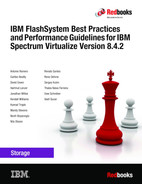
Incremental FlashCopy does not require that you copy an entire disk source volume whenever the FlashCopy mapping is started. Instead, only the changed regions on source volumes are copied to target volumes, as shown in Figure 6-3.
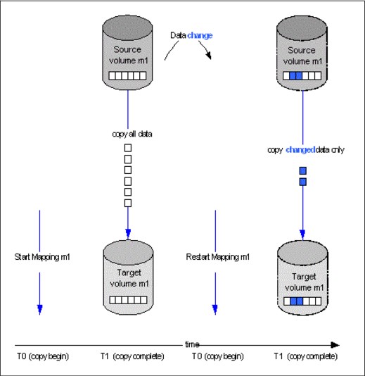
Figure 6-3 Incremental FlashCopy
If the FlashCopy mapping was stopped before the background copy completed, then when the mapping is restarted, the data that was copied before the mapping was stopped will not be copied again. For example, if an incremental mapping reaches 10 percent progress when it is stopped and then it is restarted, that 10 percent of data will not be recopied when the mapping is restarted, assuming that it was not changed.
|
Stopping an incremental FlashCopy mapping: If you are planning to stop an incremental FlashCopy mapping, make sure that the copied data on the source volume will not be changed, if possible. Otherwise, you might have an inconsistent point-in-time copy.
|
A difference value is provided in the query of a mapping, which makes it possible to know how much data has changed. This data must be copied when the Incremental FlashCopy mapping is restarted. The difference value is the percentage (0-100 percent) of data that has been changed. This data must be copied to the target volume to get a fully independent copy of the source volume.
An incremental FlashCopy can be defined setting the incremental attribute in the FlashCopy mapping.
Multiple Target FlashCopy
In Multiple Target FlashCopy, a source volume can be used in multiple FlashCopy mappings, while the target is a different volume, as shown in Figure 6-4.
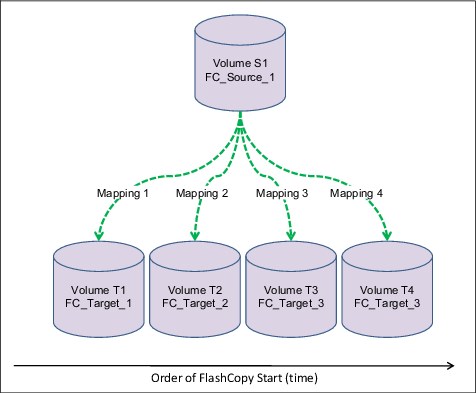
Figure 6-4 Multiple Target FlashCopy
Up to 256 different mappings are possible for each source volume. These mappings are independently controllable from each other. Multiple Target FlashCopy mappings can be members of the same or different Consistency Groups. In cases where all the mappings are in the same Consistency Group, the result of starting the Consistency Group will be to FlashCopy to multiple identical target volumes.
Cascaded FlashCopy
With Cascaded FlashCopy, you can have a source volume for one FlashCopy mapping and as the target for another FlashCopy mapping; this is referred to as a Cascaded FlashCopy. This function is illustrated in Figure 6-5.

Figure 6-5 Cascaded FlashCopy
A total of 255 mappings are possible for each cascade.
Reverse FlashCopy
Reverse FlashCopy enables FlashCopy targets to become restore points for the source without breaking the FlashCopy relationship, and without having to wait for the original copy operation to complete. It can be used in combination with the Multiple Target Flashcopy to create multiple rollback points.
A key advantage of the Multiple Target Reverse FlashCopy function is that the reverse FlashCopy does not destroy the original target. This feature enables processes that are using the target, such as a tape backup, to continue uninterrupted. IBM FlashSystem systems also allow you to create an optional copy of the source volume to be made before the reverse copy operation starts. This ability to restore back to the original source data can be useful for diagnostic purposes.
Thin-provisioned FlashCopy
When a new volume is created, you can designate it as a thin-provisioned volume, and it has a virtual capacity and a real capacity.
Virtual capacity is the volume storage capacity that is available to a host. Real capacity is the storage capacity that is allocated to a volume copy from a storage pool. In a fully allocated volume, the virtual capacity and real capacity are the same. However, in a thin-provisioned volume, the virtual capacity can be much larger than the real capacity.
The virtual capacity of a thin-provisioned volume is typically larger than its real capacity. On IBM Spectrum Virtualize based systems, the real capacity is used to store data that is written to the volume, and metadata that describes the thin-provisioned configuration of the volume. As more information is written to the volume, more of the real capacity is used.
Thin-provisioned volumes can also help to simplify server administration. Instead of assigning a volume with some capacity to an application and increasing that capacity following the needs of the application if those needs change, you can configure a volume with a large virtual capacity for the application. You can then increase or shrink the real capacity as the application needs change, without disrupting the application or server.
When you configure a thin-provisioned volume, you can use the warning level attribute to generate a warning event when the used real capacity exceeds a specified amount or percentage of the total real capacity. For example, if you have a volume with 10 GB of total capacity and you set the warning to 80 percent, an event is registered in the event log when you use 80 percent of the total capacity. This technique is useful when you need to control how much of the volume is used.
If a thin-provisioned volume does not have enough real capacity for a write operation, the volume is taken offline and an error is logged (error code 1865, event ID 060001). Access to the thin-provisioned volume is restored by either increasing the real capacity of the volume or increasing the size of the storage pool on which it is allocated.
You can use thin volumes for cascaded FlashCopy and multiple target FlashCopy. It is also possible to mix thin-provisioned with normal volumes. It can be used for incremental FlashCopy too, but using thin-provisioned volumes for incremental FlashCopy only makes sense if the source and target are thin-provisioned.
When using thin provisioned volumes on Data Reduction Pools (DRPs), consider also implementing compression because it provides several benefits:
•Reduced amount of I/O operation to the back-end as the amount of data to be actually written to the back-end reduces with compressed data. This is particularly relevant with a poorly performing back-end, but less of an issue with the high performing back-end on IBM FlashSystem systems.
•Space efficiency as the compressed data provides more capacity savings.
•Better back-end capacity monitoring, as DRP pools with thin provisioned uncompressed volumes do not provide physical allocation information.
Therefore, the recommendation is to always enable compression on DRP thin provisioned volumes.
Thin-provisioned incremental FlashCopy
The implementation of thin-provisioned volumes does not preclude the use of incremental FlashCopy on the same volumes. It does not make sense to have a fully allocated source volume and then use incremental FlashCopy, which is always a full copy at first, to copy this fully allocated source volume to a thin-provisioned target volume. However, this action is not prohibited.
Consider this optional configuration:
•A thin-provisioned source volume can be copied incrementally by using FlashCopy to a thin-provisioned target volume. Whenever the FlashCopy is performed, only data that has been modified is recopied to the target. Note that if space is allocated on the target because of I/O to the target volume, this space will not be reclaimed with subsequent FlashCopy operations.
•A fully allocated source volume can be copied incrementally using FlashCopy to another fully allocated volume at the same time as it is being copied to multiple thin-provisioned targets (taken at separate points in time). This combination allows a single full backup to be kept for recovery purposes, and separates the backup workload from the production workload. At the same time, it allows older thin-provisioned backups to be retained.
6.2.3 FlashCopy functional overview
Understanding how FlashCopy works internally helps you to configure it and enables you to obtain more benefits from it.
FlashCopy mapping states
A FlashCopy mapping defines the relationship that copies data between a source volume and a target volume. FlashCopy mappings can be either stand-alone or a member of a Consistency Group. You can perform the actions of preparing, starting, or stopping FlashCopy on either a stand-alone mapping or a Consistency Group.
A FlashCopy mapping has an attribute that represents the state of the mapping. The FlashCopy states are the following:
Idle_or_copied
Read and write caching is enabled for both the source and the target. A FlashCopy mapping exists between the source and target, but the source and target behave as independent volumes in this state.
Copying
The FlashCopy indirection layer (see “Indirection layer” on page 256) governs all I/O to the source and target volumes while the background copy is running. The background copy process is copying grains from the source to the target. Reads and writes are executed on the target as though the contents of the source were instantaneously copied to the target during the startfcmaporstartfcconsistgrp command. The source and target can be independently updated. Internally, the target depends on the source for certain tracks. Read and write caching is enabled on the source and the target.
Stopped
The FlashCopy was stopped either by a user command or by an I/O error. When a FlashCopy mapping is stopped, the integrity of the data on the target volume is lost. Therefore, while the FlashCopy mapping is in this state, the target volume is in the Offline state. To regain access to the target, the mapping must be started again (the previous point-in-time will be lost) or the FlashCopy mapping must be deleted. The source volume is accessible, and read and write caching is enabled for the source. In the Stopped state, a mapping can either be prepared again or deleted.
Stopping
The mapping is in the process of transferring data to a dependent mapping. The behavior of the target volume depends on whether the background copy process had completed while the mapping was in the Copying state. If the copy process had completed, the target volume remains online while the stopping copy process completes. If the copy process had not completed, data in the cache is discarded for the target volume. The target volume is taken offline, and the stopping copy process runs. After the data has been copied, a stop complete asynchronous event notification is issued. The mapping will move to the Idle/Copied state if the background copy has completed or to the Stopped state if the background copy has not completed. The source volume remains accessible for I/O.
Suspended
The FlashCopy was in the Copying or Stopping state when access to the metadata was lost. As a result, both the source and target volumes are offline and the background copy process has been halted. When the metadata becomes available again, the FlashCopy mapping will return to the Copying or Stopping state. Access to the source and target volumes will be restored, and the background copy or stopping process will resume. Unflushed data that was written to the source or target before the FlashCopy was suspended is pinned in cache until the FlashCopy mapping leaves the Suspended state.
Preparing
The FlashCopy is in the process of preparing the mapping. While in this state, data from cache is destaged to disk and a consistent copy of the source exists on disk. At this time, cache is operating in write-through mode and therefore writes to the source volume will experience additional latency. The target volume is reported as online, but it will not perform reads or writes. These reads and writes are failed by the SCSI front end. Before starting the FlashCopy mapping, it is important that any cache at the host level, for example, buffers on the host operating system or application, are also instructed to flush any outstanding writes to the source volume. Performing the cache flush that is required as part of the startfcmap or startfcconsistgrp command causes I/Os to be delayed waiting for the cache flush to complete. To overcome this problem, FlashCopy supports the prestartfcmap or prestartfcconsistgrp commands. These commands prepare for a FlashCopy start while still allowing I/Os to continue to the source volume.
In the Preparing state, the FlashCopy mapping is prepared by the following steps:
1. Flush any modified write data associated with the source volume from the cache. Read data for the source is left in the cache.
2. Place the cache for the source volume into write-through mode so that subsequent writes wait until data is written to disk before completing the write command that is received from the host.
3. Discard any read or write data that is associated with the target volume from the cache.
Prepared
While in the Prepared state, the FlashCopy mapping is ready to perform a start. While the FlashCopy mapping is in this state, the target volume is in the Offline state. In the Prepared state, writes to the source volume experience additional latency, because the cache is operating in write-through mode.
Figure 6-6 represent the FlashCopy mapping state diagram. It illustrates the states in which a mapping can exist, and which events are responsible for a state change.
Figure 6-6 FlashCopy mapping states diagram
FlashCopy bitmaps and grains
A bitmap is an internal data structure stored in a particular I/O Group that is used to track which data in FlashCopy mappings has been copied from the source volume to the target volume. Grains are units of data grouped together to optimize the use of the bitmap. One bit in each bitmap represents the state of one grain. FlashCopy grain can be either 64 KB or 256 KB.
A FlashCopy bitmap takes up the bitmap space in the memory of the I/O group that must be shared with bitmaps of other features (such as Remote Copy bitmaps, volume mirroring bitmaps, and RAID bitmaps).
Indirection layer
The FlashCopy indirection layer governs the I/O to the source and target volumes when a FlashCopy mapping is started. This process is done by using a FlashCopy bitmap. The purpose of the FlashCopy indirection layer is to enable both the source and target volumes for read and write I/O immediately after FlashCopy starts.
The following description illustrates how the FlashCopy indirection layer works when a FlashCopy mapping is prepared and then started.
When a FlashCopy mapping is prepared and started, the following sequence is applied:
1. Flush the write cache to the source volume or volumes that are part of a Consistency Group.
2. Put the cache into write-through mode on the source volumes.
3. Discard the cache for the target volumes.
4. Establish a sync point on all of the source volumes in the Consistency Group (creating the FlashCopy bitmap).
5. Ensure that the indirection layer governs all of the I/O to the source volumes and target.
6. Enable the cache on source volumes and target volumes.
FlashCopy provides the semantics of a point-in-time copy that uses the indirection layer, which intercepts I/O that is directed at either the source or target volumes. The act of starting a FlashCopy mapping causes this indirection layer to become active in the I/O path, which occurs automatically across all FlashCopy mappings in the Consistency Group. The indirection layer then determines how each of the I/O is to be routed based on the following factors:
•The volume and the logical block address (LBA) to which the I/O is addressed
•Its direction (read or write)
The indirection layer allows the I/O to go through the underlying volume preserving the point-in-time copy. In order to do that, the Spectrum Virtualize code uses two mechanisms:
•Copy-on-Write (CoW). With this mechanism, when a write operation occurs in the source volume, a portion of data (grain) containing the data to be modified is copied to the target volume before the operation completion.
•Redirect-on-Write (RoW). With this mechanism, when a write operation occurs in the source volume, the data to be modified is written in another area leaving the original data unmodified to be used by the target volume.
Spectrum Virtualize implements CoW and RoW logics transparently to the user with the aim to optimize the performance and capacity. By using the RoW mechanism, the performance can improve by reducing the number of physical IOs for the write operations, while a significant capacity-saving can be achieved by improving the overall deduplication ratio.
The RoW was introduced with IBM Spectrum Virtualize version 8.4 and is used in the following conditions:
•Source and target volumes in the same pool.
•Source and target volumes in the same IO group.
•The pool that contains the source and target volumes must be a DRP.
•Source and target volumes do not participate in a volume mirroring relationship.
•Source and target volumes are not fully allocated.
In all the cases in which the RoW in not applicable, the CoW is used.
Table 6-2 lists the indirection layer algorithm in case of CoW.
Table 6-2 Summary table of the FlashCopy indirection layer algorithm
|
Volume being accessed
|
Has the grain been copied?
|
Host I/O operation
| |
|
Read
|
Write
| ||
|
Source
|
No
|
Read from the source volume.
|
Copy grain to the most recently started target for this source, then write to the source.
|
|
Yes
|
Read from the source volume.
|
Write to the source volume.
| |
|
Target
|
No
|
If any newer targets exist for this source in which this grain has already been copied, read from the oldest of these targets. Otherwise, read from the source.
|
Hold the write. Check the dependency target volumes to see whether the grain has been copied. If the grain is not already copied to the next oldest target for this source, copy the grain to the next oldest target. Then, write to the target.
|
|
Yes
|
Read from the target volume.
|
Write to the target volume.
| |
Interaction with cache
The Spectrum Virtualize technology provides a two-layer cache, as follows:
•Upper cache serves mostly as write cache and hides the write latency from the hosts and application.
•Lower cache is a read/write cache and optimizes I/O to and from disks.
Figure 6-7 shows the IBM Spectrum Virtualize cache architecture.

Figure 6-7 New cache architecture
The CoW process might introduce significant latency into write operations. To isolate the active application from this additional latency, the FlashCopy indirection layer is placed logically between the upper and lower cache. Therefore, the additional latency that is introduced by the CoW process is encountered only by the internal cache operations, and not by the application.
The logical placement of the FlashCopy indirection layer is shown in Figure 6-8.

Figure 6-8 Logical placement of the FlashCopy indirection layer
The two-level cache architecture provides performance benefits to the FlashCopy mechanism. Because the FlashCopy layer is above the lower cache in the IBM Spectrum Virtualize software stack, it can benefit from read prefetching and coalescing writes to back-end storage.
Also, preparing FlashCopy is fast because upper cache write data does not have to go directly to back-end storage, but to the lower cache layer only.
Interaction and dependency between Multiple Target FlashCopy mappings
Figure 6-9 on page 260 shows a set of three FlashCopy mappings that share a common source. The FlashCopy mappings target volumes Target 1, Target 2, and Target 3.
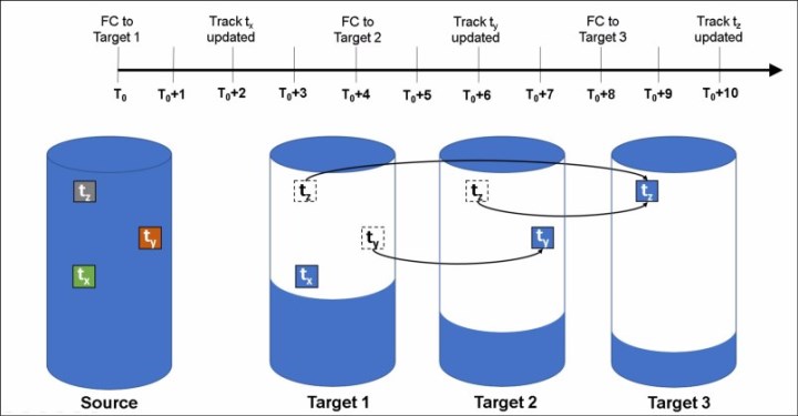
Figure 6-9 Interaction between Multiple Target FlashCopy mappings
Consider the following events timeline:
•At time T0 a FlashCopy mapping is started between the source and the Target 1.
•At time T0+2 the track tx is updated in the source. Since this track has not yet been copied in background on Target 1, the copy-on-write process copies this track to the Target 1 before being updated on the source.
•At time T0+4 a FlashCopy mapping is started between the source and the Target 2.
•At time T0+6 the track ty is updated in the source. Because this track has not yet been copied in background on Target 2, the copy-on-write process copies this track to the Target 2 only before being updated on the source.
•At time T0+8 a FlashCopy mapping is started between the source and the Target 3.
•At time T0+10 the track tz is updated in the source. Because this track has not yet been copied in background on Target 3, the copy-on-write process copies this track to the Target 3 only before being updated on the source.
As a result of this sequence of events, the configuration in Figure 6-9 has the following characteristics:
•Target 1 is dependent upon Target 2 and Target 3. It remains dependent until all of Target 1 has been copied. No target depends on Target 1, so the mapping can be stopped without need to copy any data to maintain the consistency in the other targets.
•Target 2 depends on Target 3, and will remain dependent until all of Target 2 has been copied. Target 1 depends on Target 2, so if this mapping is stopped, the cleanup process is started to copy all data that is uniquely held on this mapping (that is ty) to Target 1.
•Target 3 is not dependent on any target, but it has Target 1 and Target 2 depending on it, so if this mapping is stopped the cleanup process is started to copy all data that is uniquely held on this mapping (that is tz) to Target 2.
Target writes with Multiple Target FlashCopy
A write to an intermediate or newest target volume must consider the state of the grain within its own mapping, and the state of the grain of the next oldest mapping:
•If the grain of the next oldest mapping has not been copied yet, it must be copied before the write is allowed to proceed to preserve the contents of the next oldest mapping. The data that is written to the next oldest mapping comes from a target or source.
•If the grain in the target being written has not yet been copied, the grain is copied from the oldest already copied grain in the mappings that are newer than the target, or the source if none are already copied. After this copy is done, the write can be applied to the target.
Target reads with Multiple Target FlashCopy
If the grain being read has already been copied from the source to the target, the read simply returns data from the target being read. If the grain has not been copied, each of the newer mappings is examined in turn and the read is performed from the first copy found. If none are found, the read is performed from the source.
6.2.4 FlashCopy planning considerations
The FlashCopy function, like all the advanced IBM FlashSystem products features, offers useful capabilities. However, some basic planning considerations are to be followed for a successful implementation.
FlashCopy configurations limits
To plan for and implement FlashCopy, you must check the configuration limits and adhere to them. Table 6-3 lists the system limits that apply to the latest version as of this writing.
Table 6-3 FlashCopy properties and maximum configurations
|
FlashCopy property
|
Maximum
|
Comment
|
|
FlashCopy targets per source
|
256
|
This maximum is the maximum number of FlashCopy mappings that can exist with the same source volume.
|
|
FlashCopy mappings per system
|
15864
|
This maximum is the maximum number of FlashCopy mappings per system.
|
|
FlashCopy Consistency Groups per system
|
500
|
This maximum is an arbitrary limit that is policed by the software.
|
|
FlashCopy volume space per I/O Group
|
4096 TB
|
This maximum is a limit on the quantity of FlashCopy mappings by using bitmap space from one I/O Group.
|
|
FlashCopy mappings per Consistency Group
|
512
|
This limit is due to the time that is taken to prepare a Consistency Group with many mappings.
|
|
Configuration limits: The configuration limits always change with the introduction of new hardware and software capabilities. For more information about the latest configuration limits, see this IBM Support web page.
|
The total amount of cache memory reserved for the FlashCopy bitmaps limits the amount of capacity that can be used as a FlashCopy target. Table 6-4 shows the relationship of bitmap space to FlashCopy address space, depending on the size of the grain and the kind of FlashCopy service being used.
Table 6-4 Relationship of bitmap space to FlashCopy address space for the specified I/O Group
|
Copy service
|
Grain size (KB)
|
1 MB of memory provides the following volume capacity for the specified I/O Group
|
|
FlashCopy
|
256
|
2 TB of target volume capacity
|
|
FlashCopy
|
64
|
512 GB of target volume capacity
|
|
Incremental FlashCopy
|
256
|
1 TB of target volume capacity
|
|
Incremental FlashCopy
|
64
|
256 GB of target volume capacity
|
|
Mapping consideration: For multiple FlashCopy targets, you must consider the number of mappings. For example, for a mapping with a 256 KB grain size, 8 KB of memory allows one mapping between a 16 GB source volume and a 16 GB target volume. Alternatively, for a mapping with a 256 KB grain size, 8 KB of memory allows two mappings between one 8 GB source volume and two 8 GB target volumes.
When you create a FlashCopy mapping, if you specify an I/O Group other than the I/O Group of the source volume, the memory accounting goes towards the specified I/O Group, not towards the I/O Group of the source volume.
|
The default amount of memory for FlashCopy is 20 MB. This value can be increased or decreased by using the chiogrp command or through the GUI. The maximum amount of memory that can be specified for FlashCopy is 2048 MB (512 MB for 32-bit systems). The maximum combined amount of memory across all copy services features is 2600 MB (552 MB for 32-bit systems).
|
Bitmap allocation: When creating a FlashCopy mapping, you can optionally specify the I/O group where the bitmap is allocated. If you specify an I/O Group other than the I/O Group of the source volume, the memory accounting goes towards the specified I/O Group, not towards the I/O Group of the source volume. This option can be useful when an I/O group is exhausting the memory that is allocated to the FlashCopy bitmaps and no more free memory is available in the I/O group.
|
FlashCopy general restrictions
The following implementation restrictions apply to FlashCopy:
•The size of source and target volumes must be the same when creating a FlashCopy mapping.
•Multiple FlashCopy mappings that use the same target volume can be defined, but only one of these mappings can be started at a time. This limitation means that no multiple FlashCopy can be active to the same target volume.
•The following restrictions apply when expanding or shrinking volumes that are defined in a FlashCopy mapping:
– Target volumes cannot be shrunk
– Source volume can be shrunk, but only to the largest starting size of a target volume (in a multiple target or cascading mappings) when in copying or stopping state.
– Source and target volumes must be same size when the mapping is prepared or started.
– Source and target volumes can be expanded in any order except in case of incremental FlashCopy where the target volume must be expanded before the source volume can be expanded.
|
Note: Expanding or shrinking volumes that are participating in a FlashCopy map is allowed with code level 8.4.2 or later.
|
•In a cascading FlashCopy, the grain size of all the FlashCopy mappings that participate must be the same.
•In a multi-target FlashCopy, the grain size of all the FlashCopy mappings that participate must be the same.
•In a reverse FlashCopy, the grain size of all the FlashCopy mappings that participate must be the same.
•No FlashCopy mapping can be added to a consistency group while the FlashCopy mapping status is Copying.
•No FlashCopy mapping can be added to a consistency group while the consistency group status is Copying.
•The use of Consistency Groups is restricted when using Cascading FlashCopy. A Consistency Group serves the purpose of starting FlashCopy mappings at the same point in time. Within the same Consistency Group, it is not possible to have mappings with these conditions:
– The source volume of one mapping is the target of another mapping.
– The target volume of one mapping is the source volume for another mapping.
These combinations are not useful because within a Consistency Group, mappings cannot be established in a certain order. This limitation renders the content of the target volume undefined. For instance, it is not possible to determine whether the first mapping was established before the target volume of the first mapping that acts as a source volume for the second mapping.
Even if it were possible to ensure the order in which the mappings are established within a Consistency Group, the result is equal to Multi Target FlashCopy (two volumes holding the same target data for one source volume). In other words, a cascade is useful for copying volumes in a certain order (and copying the changed content targets of FlashCopies), rather than at the same time in an undefined order (from within one single Consistency Group).
•Source and target volumes can be used as primary in a Remote Copy relationship. For more information about the FlashCopy and the Remote Copy possible interactions, see “Interaction between Remote Copy and FlashCopy” on page 304.
FlashCopy presets
The IBM FlashSystem GUI interface provides three FlashCopy presets (Snapshot, Clone, and Backup) to simplify the more common FlashCopy operations. Figure 6-10 shows the preset selection window in the GUI.
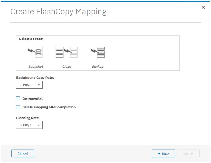
Figure 6-10 GUI FlashCopy Presets
Although these presets meet most FlashCopy requirements, they do not provide support for all possible FlashCopy options. If more specialized options are required that are not supported by the presets, the options must be performed by using CLI commands.
This section describes the three preset options and their use cases.
Snapshot
This preset creates a copy-on-write point-in-time copy. The snapshot is not intended to be an independent copy. Instead, the copy is used to maintain a view of the production data at the time that the snapshot is created. Therefore, the snapshot holds only the data from regions of the production volume that have changed since the snapshot was created. Because the snapshot preset uses thin provisioning, only the capacity that is required for the changes
is used.
is used.
Snapshot uses the following preset parameters:
•Background copy: None
•Incremental: No
•Delete after completion: No
•Cleaning rate: No
•Primary copy source pool: Target pool
A typical use case for the Snapshot is when the user wants to produce a copy of a volume without affecting the availability of the volume. The user does not anticipate many changes to be made to the source or target volume. A significant proportion of the volumes remains unchanged.
By ensuring that only changes require a copy of data to be made, the total amount of disk space that is required for the copy is reduced. Therefore, many Snapshot copies can be used in the environment.
Snapshots are useful for providing protection against corruption or similar issues with the validity of the data. However, they do not provide protection from physical controller failures. Snapshots can also provide a vehicle for performing repeatable testing (including “what-if” modeling that is based on production data) without requiring a full copy of the data to be provisioned.
Clone
The clone preset creates a replica of the volume, which can then be changed without affecting the original volume. After the copy completes, the mapping that was created by the preset is automatically deleted.
Clone uses the following preset parameters:
•Background copy rate: 50
•Incremental: No
•Delete after completion: Yes
•Cleaning rate: 50
•Primary copy source pool: Target pool
A typical use case for the Snapshot is when users want a copy of the volume that they can modify without affecting the original volume. After the clone is established, there is no expectation that it is refreshed or that there is any further need to reference the original production data again. If the source is thin-provisioned, the target is thin-provisioned for the auto-create target.
Backup
The backup preset creates a point-in-time replica of the production data. After the copy completes, the backup view can be refreshed from the production data, with minimal copying of data from the production volume to the backup volume.
Backup uses the following preset parameters:
•Background Copy rate: 50
•Incremental: Yes
•Delete after completion: No
•Cleaning rate: 50
•Primary copy source pool: Target pool
The Backup preset can be used when the user wants to create a copy of the volume that can be used as a backup if the source becomes unavailable. This unavailability can happen during loss of the underlying physical controller. The user plans to periodically update the secondary copy, and does not want to suffer from the resource demands of creating a new copy each time.
Incremental FlashCopy times are faster than full copy, which helps to reduce the window where the new backup is not yet fully effective. If the source is thin-provisioned, the target is also thin-provisioned in this option for the auto-create target.
Another use case, which is not supported by the name, is to create and maintain (periodically refresh) an independent image. This image can be subjected to intensive I/O (for example, data mining) without affecting the source volume’s performance.
Thin provisioning considerations
When creating FlashCopy with thin provisioned target volumes, the no-copy option often is used. The real size of a thin provisioned volume is an attribute that defines how much physical capacity is reserved for the volume. The real size can vary 0 - 100% of the virtual capacity.
When thin provisioned volumes are used as FlashCopy targets, it is important to provide a non-zero real size. This size is required because when the FlashCopy is started, the copy-on-write process requires to allocate capacity on the target volumes. If some capacity is not yet allocated, the write IO can be delayed until the capacity is made available (as with thin provisioned volumes with zero real size). Often, the write caching hides this effect, but in the case of heavy write workloads, the performance could be affected.
Sizing consideration
When Thin Provisioned FlashCopy is used, an estimation of the physical capacity consumption is required. Consider that while a FlashCopy is active, the thin provisioned target volume allocates physical capacity whenever a grain is modified for the first time on source or target volume.
The following factors must be considered that so that an accurate sizing can be completed:
•The FlashCopy duration in terms of seconds (D).
•The write operation per second (W).
•The grain size in terms of KB (G).
•The rewrite factor. This factor represents the average chance that a write operation reoccurs in the same grain (R) in percentage
While the first three factors are easy to assess, the rewrite factor can be only roughly estimated as it is dependent on the workload type and the FlashCopy duration. The used capacity (CC) of a thin provisioned target volume of C size while the FlashCopy is active can be estimated by using the following equation:
CC = min{(W - W x R) x G x D,C}
For example, consider a 100 GB volume that has a FlashCopy active for 3 hours (10.800 seconds) with a grain size of 64 K. Consider also a write workload of 100 IOPS with a rewrite factor of 85% (85% of writes occur on the same grains). In this case, the estimation of the used capacity is:
CC = (100 - 85) x 64 x 10.800 = 10.368.000 KB = 9,88 GB
|
Important: Consider the following points:
•The recommendation with thin provisioned target volumes is to assign at least 2 GB of real capacity.
•Thin provisioned FlashCopy can greatly benefit from the Redirect-on-Write capability that was introduced with Spectrum Virtualize version 8.4. For more information, see “Indirection layer” on page 256.
|
Grain size considerations
When creating a mapping a grain size of 64 KB can be specified as compared to the default 256 KB. This smaller grain size has been introduced specifically for the incremental FlashCopy, even though its use is not restricted to the incremental mappings.
In an incremental FlashCopy, the modified data is identified by using the bitmaps. The amount of data to be copied when refreshing the mapping depends on the grain size. If the grain size is 64 KB, as compared to 256 KB, there might be less data to copy to get a fully independent copy of the source again.
The following are the preferred settings for thin-provisioned FlashCopy:
•Thin-provisioned volume grain size should be equal to the FlashCopy grain size. Anyway if the 256 KB thin-provisioned volume grain size is chosen, it is still beneficial to limit the FlashCopy grain size to 64 KB. It is possible to minimize the performance impact to the source volume, even though this size increases the I/O workload on the target volume.
•Thin-provisioned volume grain size must be 64 KB for the best performance and the best space efficiency.
The exception is where the thin target volume is going to become a production volume (and is likely to be subjected to ongoing heavy I/O). In this case, the 256 KB thin-provisioned grain size is preferable because it provides better long-term I/O performance at the expense of a slower initial copy.
|
FlashCopy limitation: Configurations with large numbers of FlashCopy/Remote Copy relationships might be forced to choose a 256 KB grain size for FlashCopy to avoid constraints on the amount of bitmap memory.
|
Cascading FlashCopy and Multi Target FlashCopy require that all the mappings that are participating in the FlashCopy chain feature the same grain size. For more information, see “FlashCopy general restrictions” on page 262.
Volume placement considerations
The source and target volumes placement among the pools and the I/O groups must be planned to minimize the effect of the underlying FlashCopy processes. In normal condition (that is with all the canisters fully operative), the FlashCopy background copy workload distribution follows this schema:
•The preferred node of the source volume is responsible for the background copy read operations.
•The preferred node of the target volume is responsible for the background copy write operations.
Table 6-5 shows how the back-end I/O operations are distributed across the nodes.
Table 6-5 Workload distribution for back-end I/O operations
|
|
Read from source
|
Read from target
|
Write to source
|
Write to target
|
|
Node that performs the back-end I/O if the grain is copied
|
Preferred node in source volume’s I/O group
|
Preferred node in target volume’s I/O group
|
Preferred node in source volume’s I/O group
|
Preferred node in target volume’s I/O group
|
|
Node that performs the back-end I/O if the grain is not yet copied
|
Preferred node in source volume’s I/O group
|
Preferred node in source volume’s I/O group
|
The preferred node in source volume’s I/O group will read and write, and the preferred node in target volume’s I/O group will write
|
The preferred node in source volume’s I/O group will read, and the preferred node in target volume’s I/O group will write
|
The data transfer among the source and the target volume’s preferred nodes occurs through the node-to-node connectivity. Consider the following volume placement alternatives:
•Source and target volumes use the same preferred node.
In this scenario, the node that is acting as preferred for source and target volume manages all the read and write FlashCopy operations. Only resources from this node are used for the FlashCopy operations, and no node-to-node bandwidth is used.
•Source and target volumes use the different preferred node.
In this scenario, both nodes that are acting as preferred nodes manage read and write FlashCopy operations according to the previously described scenarios. The data that is transferred between the two preferred nodes goes through the node-to-node network.
Both alternatives described have advantages and disadvantages, but in general option 1 (source and target volumes use the same preferred node) is preferred. Consider the following exceptions:
•A clustered IBM FlashSystem system with multiple I/O groups in HyperSwap, where the source volumes are evenly spread across all the nodes.
In this case the preferred node placement should follow the location of the source and target volumes on the back-end storage. For example, if the source volume is on site A and the target volume is on site B, then the target volumes preferred node must be in site B. Placing the target volumes preferred node in site A will cause the re-direction of the FlashCopy write operation through the node-to-node network.
•A clustered IBM FlashSystem system with multiple control enclosures, where the source volumes are evenly spread across all the canisters.
In this case the preferred node placement should follow the location of source and target volumes on the internal storage. For example, if the source volume is on the internal storage attached to control enclosure A and the target volume is on internal storage attached to control enclosure B, then the target volumes preferred node must be in one canister of control enclosure B. Placing the target volumes preferred node on control enclosure A will cause the re-direction of the FlashCopy write operation through the node-to-node network.
Placement on the back-end storage is mainly driven by the availability requirements. Generally, use different back-end storage controllers or arrays for the source and target volumes.
|
DRP optimized snapshots: To use the Redirect-on-Write capability that was introduced with Spectrum Virtualize version 8.4, check the volume placement restrictions that are described in “Indirection layer” on page 256.
|
Background copy considerations
The background copy process uses internal resources, such as CPU, memory, and bandwidth. This copy process tries to reach the target copy data rate for every volume according to the background copy rate parameter setting (see Table 6-1 on page 248).
If the copy process is unable to achieve these goals, it starts contending resources to the foreground I/O (that is the I/O coming from the hosts). As result, both background copy and foreground I/O will tend to see an increase in latency and therefore reduction in throughput compared to the situation when the bandwidth not been limited. Degradation is graceful. Both background copy and foreground I/O continue to make progress, and will not stop, hang, or cause the node to fail.
To avoid any impact on the foreground I/O, that is in the hosts response time, carefully plan the background copy activity, taking in account the overall workload running in the systems. The background copy basically reads and writes data to managed disks. Usually, the most affected component is the back-end storage. CPU and memory are not normally significantly affected by the copy activity.
The theoretical added workload due to the background copy is easily estimable. For instance, starting 20 FlashCopy with a background copy rate of 70 each adds a maximum throughput of 160 MBps for the reads and 160 MBps for the writes.
The source and target volumes distribution on the back-end storage determines where this workload is going to be added. The duration of the background copy depends on the amount of data to be copied. This amount is the total size of volumes for full background copy or the amount of data that is modified for incremental copy refresh.
Performance monitoring tools like IBM Spectrum Control can be used to evaluate the existing workload on the back-end storage in a specific time window. By adding this workload to the foreseen background copy workload, you can estimate the overall workload running toward the back-end storage. Disk performance simulation tools, like Disk Magic or StorM, can be used to estimate the effect, if any, of the added back-end workload to the host service time during the background copy window. The outcomes of this analysis can provide useful hints for the background copy rate settings.
When performance monitoring and simulation tools are not available, use a conservative and progressive approach. Consider that the background copy setting can be modified at any time, even when the FlashCopy is already started. The background copy process can even be completely stopped by setting the background copy rate to 0.
Initially set the background copy rate value to add a limited workload to the back-end (for example less than 100 MBps). If no effects on hosts are noticed, the background copy rate value can be increased. Do this process until you see negative effects. Note that the background copy rate setting follows an exponential scale, so changing, for instance, from 50 to 60 doubles the data rate goal from 2 MBps to 4 MBps.
Cleaning process and Cleaning Rate
The Cleaning Rate is the rate at which the data is copied among dependent FlashCopies, such as Cascaded and Multi Target FlashCopy. The Cleaning process aims to release the dependency of a mapping in such a way that it can be stopped immediately (without going to the stopping state). The typical use case for setting the Cleaning Rate is when it is required to stop a Cascaded or Multi Target FlashCopy that is not the oldest in the FlashCopy chain. In this case to avoid the stopping state lasting for a long time, the cleaning rate can be adjusted accordingly.
An interaction occurs between the background copy rate and the Cleaning Rate settings:
•Background copy = 0 and Cleaning Rate = 0
No background copy or cleaning take place. When the mapping is stopped, it goes into stopping state and a cleaning process starts with the default cleaning rate, which is 50 or
2 MBps.
2 MBps.
•Background copy > 0 and Cleaning Rate = 0
The background copy takes place at the background copy rate but no cleaning process is started. When the mapping is stopped, it goes into stopping state and a cleaning process starts with the default cleaning rate (50 or 2 MBps).
•Background copy = 0 and Cleaning Rate > 0
No background copy takes place, but the cleaning process runs at the cleaning rate. When the mapping is stopped, the cleaning completes (if not yet completed) at the cleaning rate.
•Background copy > 0 and Cleaning Rate > 0
The background copy takes place at the background copy rate but no cleaning process is started. When the mapping is stopped, it goes into stopping state and a cleaning process starts with the specified cleaning rate.
Regarding the workload considerations for the cleaning process, the same guidelines as for background copy apply.
Host and application considerations to ensure FlashCopy integrity
Because FlashCopy is at the block level, it is necessary to understand the interaction between your application and the host operating system. From a logical standpoint, it is easiest to think of these objects as “layers” that sit on top of one another. The application is the topmost layer, and beneath it is the operating system layer.
Both of these layers have various levels and methods of caching data to provide better speed. Because IBM FlashSystem systems, and therefore FlashCopy, sit below these layers, they are unaware of the cache at the application or operating system layers.
To ensure the integrity of the copy that is made, it is necessary to flush the host operating system and application cache for any outstanding reads or writes before the FlashCopy operation is performed. Failing to flush the host operating system and application cache produces what is referred to as a crash consistent copy.
The resulting copy requires the same type of recovery procedure, such as log replay and file system checks, that is required following a host crash. FlashCopies that are crash consistent often can be used following file system and application recovery procedures.
|
Note: Although the best way to perform FlashCopy is to flush host cache first, some companies, such as Oracle, support using snapshots without it, as stated in Metalink note 604683.1.
|
Various operating systems and applications provide facilities to stop I/O operations and ensure that all data is flushed from host cache. If these facilities are available, they can be used to prepare for a FlashCopy operation. When this type of facility is not available, the host cache must be flushed manually by quiescing the application and unmounting the file system or drives.
|
Preferred practice: From a practical standpoint, when you have an application that is backed by a database and you want to make a FlashCopy of that application’s data, it is sufficient in most cases to use the write-suspend method that is available in most modern databases. You can use this method because the database maintains strict control over I/O.
This method is as opposed to flushing data from both the application and the backing database, which is always the suggested method because it is safer. However, this method can be used when facilities do not exist or your environment includes time sensitivity.
|
6.3 Remote Copy services
IBM FlashSystem technology offers various Remote Copy services functions that address Disaster Recovery and Business Continuity needs.
Metro Mirror is designed for metropolitan distances with a zero recovery point objective (RPO), which is zero data loss. This objective is achieved with a synchronous copy of volumes. Writes are not acknowledged until they are committed to both storage systems. By definition, any vendors’ synchronous replication makes the host wait for write I/Os to complete at both the local and remote storage systems, and includes round-trip network latencies. Metro Mirror has the following characteristics:
•Zero RPO
•Synchronous
•Production application performance that is affected by round-trip latency
Global Mirror technologies are designed to minimize the network latency effects by replicating asynchronously. Spectrum Virtualize provides two types of asynchronous mirroring technology:
•The standard Global Mirror (referred to as Global Mirror)
•The Global Mirror with Change Volume (GMCV)
With the Global Mirror, writes are acknowledged as soon as they can be committed to the local storage system, sequence-tagged, and passed on to the replication network. This technique allows Global Mirror to be used over longer distances. By definition, any vendors’ asynchronous replication results in an RPO greater than zero. However, for Global Mirror, the RPO is quite small, typically anywhere from several milliseconds to some number of seconds.
Although Global Mirror is asynchronous, the RPO is still small, and thus the network and the remote storage system must both still be able to cope with peaks in traffic. Global Mirror has the following characteristics:
•Near-zero RPO
•Asynchronous
•Production application performance that is affected by I/O sequencing preparation time
GMCV provides an option to replicate point-in-time copies of volumes. This option generally requires lower bandwidth because it is the average rather than the peak throughput that must be accommodated. The RPO for Global Mirror with Change Volumes is higher than traditional Global Mirror. Global Mirror with Change Volumes has the following characteristics:
•Larger RPO
•Point-in-time copies
•Asynchronous
•Possible system performance effect because point-in-time copies are created locally
Successful implementation of Remote Copy depends on taking a holistic approach in which you consider all components and their associated properties. The components and properties include host application sensitivity, local and remote SAN configurations, local and remote system and storage configuration, and the inter-system network.
6.3.1 Remote Copy use cases
Data replication techniques are the foundations of Disaster Recovery and Business Continuity solutions. Besides these common use cases, Remote Copy technologies can be used in other data movement scenarios, as described in the following sections.
Storage systems renewal
Remote Copy functions can be used to facilitate the migration of data between storage systems while minimizing downtime for applications. By using remote copy, application data can be copied from an IBM Spectrum Virtualize-based system to another, while applications remain online. After the volumes are fully copied and synchronized, the application can be stopped and then immediately started on the new storage system.
Starting with IBM Spectrum Virtualize version 8.4.2, the Nondisruptive Volume Migration capability was introduced. This feature uses the Remote Copy capabilities to transparently move host volumes between IBM Spectrum Virtualize based systems.
For more information, see 5.8, “Volume migration” on page 223.
Data center moving
Remote Copy functions can be used to move data between Spectrum Virtualize-based systems to facilitate data centers moving operations. By using remote copy, application data can be copied from volumes in a source data center to volumes in another data center while applications remain online. After the volumes are fully copied and synchronized, the applications can be stopped and then immediately started in the target data center.
6.3.2 Remote Copy functional overview
This section presents the terminology and the basic functional aspects of the Remote Copy services.
Common terminology and definitions
When such a breadth of technology areas is covered, the same technology component can have multiple terms and definitions. This document uses the following definitions:
•Local system or master system
The system on which the foreground applications run.
•Local hosts
Hosts that run on the foreground applications.
•Master volume or source volume
The local volume that is being mirrored. The volume has nonrestricted access. Mapped hosts can read and write to the volume.
•inter-system link or inter-system network
The network that provides connectivity between the local and the remote site. It can be a Fibre Channel (FC) network (SAN), an IP network, or a combination of the two.
•Remote system or auxiliary system
The system that holds the remote mirrored copy.
•Auxiliary volume or target volume
The remote volume that holds the mirrored copy. It is read-access only.
•Remote copy
A generic term that is used to describe a Metro Mirror or Global Mirror relationship in which data on the source volume is mirrored to an identical copy on a target volume. Often the two copies are separated by some distance, which is why the term remote is used to describe the copies. However, having remote copies is not a prerequisite. A Remote Copy relationship includes the following states:
– Consistent relationship
A Remote Copy relationship where the data set on the target volume represents a data set on the source volumes at a certain point.
– Synchronized relationship
A relationship is synchronized if it is consistent and the point that the target volume represents is the current point. The target volume contains identical data as the source volume.
•Synchronous Remote Copy
•Writes to the source and target volumes that are committed in the foreground before confirmation is sent about completion to the local host application. Metro Mirror is a synchronous Remote Copy type.
•Asynchronous remote copy
A foreground write I/O is acknowledged as complete to the local host application before the mirrored foreground write I/O is cached at the remote system. Mirrored foreground writes are processed asynchronously at the remote system, but in way that a consistent copy is always present in the remote system. Global Mirror and GMCV are asynchronous Remote Copy types.
•The background copy process manages the initial synchronization or resynchronization processes between source volumes to target mirrored volumes on a remote system.
•Foreground I/O reads and writes I/O on a local SAN, which generates a mirrored foreground write I/O that is across the inter-system network and remote SAN.
Figure 6-11 shows some of the concepts of remote copy.
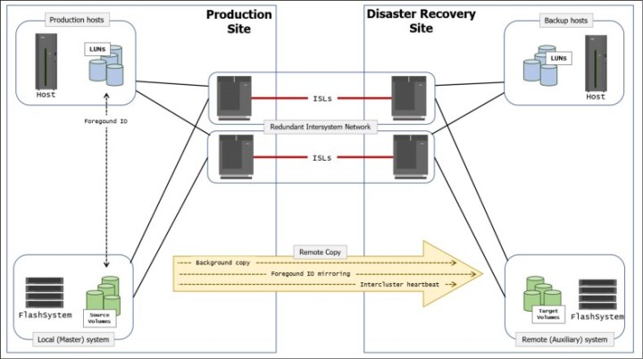
Figure 6-11 Remote Copy components and applications
A successful implementation of inter-system Remote Copy services significantly depends on the quality and configuration of the inter-system network.
Remote Copy partnerships and relationships
A Remote Copy partnership is a partnership that is established between a master (local) system and an auxiliary (remote) system, as shown in Figure 6-12.

Figure 6-12 Remote Copy partnership
Partnerships are established between two systems by issuing the mkfcpartnership or mkippartnership command once from each end of the partnership. The following parameters must be specified:
•The remote system name (or ID).
•The link bandwidth (in Mbps).
•The background copy rate as a percentage of the link bandwidth.
•The background copy parameter that determines the maximum speed of the initial synchronization and resynchronization of the relationships.
|
Tip: To establish a fully functional Metro Mirror or Global Mirror partnership, issue the mkfcpartnership or mkippartnership command from both systems.
|
In addition to the background copy rate setting, the initial synchronization can be adjusted at relationship level with the relationship_bandwidth_limit parameter. The relationship_bandwidth_limit is a system-wide parameter that sets the maximum bandwidth that can be used to initially synchronize a single relationship.
After background synchronization or resynchronization is complete, a Remote Copy relationship provides and maintains a consistent mirrored copy of a source volume to a target volume.
Copy directions and default roles
When a Remote Copy relationship is created, the source volume is assigned the role of the master, and the target volume is assigned the role of the auxiliary. This design implies that the initial copy direction of mirrored foreground writes and background resynchronization writes (if applicable) is from master to auxiliary. When a Remote Copy relationship is initially started, the master volume assumes the role of primary volume, while the auxiliary volume became secondary volumes.
After the initial synchronization is complete, you can change the copy direction (see Figure 6-13) by switching the roles of primary and secondary. The ability to change roles is used to facilitate disaster recovery.
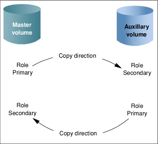
Figure 6-13 Role and direction changes
|
Attention: When the direction of the relationship is changed, the roles primary/secondary of the volumes are altered. A consequence is that the read/write properties are also changed, meaning that the master volume takes on a secondary role and becomes read-only.
|
Consistency Groups
A Consistency Group (CG) is a collection of relationships that can be treated as one entity. This technique is used to preserve write order consistency across a group of volumes that pertain to one application, for example, a database volume and a database log file volume.
After a Remote Copy relationship is added into a Consistency Group, you cannot manage the relationship in isolation from the Consistency Group. So, for example, issuing a stoprcrelationship command on the stand-alone volume would fail because the system knows that the relationship is part of a Consistency Group.
Similarly to the Remote Copy relationships, also a Consistency Group, when created, assigns the role of master to the source storage system and auxiliary to the target storage system.
Consider the following points regarding Consistency Groups:
•Each volume relationship can belong to only one Consistency Group.
•Volume relationships can also be stand-alone; that is, not in any Consistency Group.
•Consistency Groups can also be created and left empty or can contain one or many relationships.
•You can create up to 256 Consistency Groups on a system.
•All volume relationships in a Consistency Group must have matching primary and secondary systems, but they do not need to share I/O groups.
•All relationships in a Consistency Group have the same copy direction and state.
•Each Consistency Group is either for Metro Mirror or for Global Mirror relationships, but not both. This choice is determined by the first volume relationship that is added to the Consistency Group.
|
Consistency Group consideration: A Consistency Group relationship does not have to be in a directly matching I/O group number at each site. A Consistency Group owned by I/O group 1 at the local site does not have to be owned by I/O group 1 at the remote site. If you have more than one I/O group at either site, you can create the relationship between any two I/O groups. This technique spreads the workload, for example, from local I/O group 1 to remote I/O group 2.
|
Streams
Consistency Groups can also be used as a way to spread replication workload across multiple streams within a partnership.
The Metro or Global Mirror partnership architecture allocates traffic from each Consistency Group in a round-robin fashion across 16 streams. That is, cg0 traffic goes into stream0, and cg1 traffic goes into stream1.
Any volume that is not in a Consistency Group also goes into stream0. You might want to consider creating an empty Consistency Group 0 so that stand-alone volumes do not share a stream with active Consistency Group volumes.
It can also pay to optimize your streams by creating more Consistency Groups. Within each stream, each batch of writes must be processed in tag sequence order and any delays in processing any particular write also delays the writes behind it in the stream. Having more streams (up to 16) reduces this kind of potential congestion.
Each stream is sequence-tag-processed by one node, so generally you would want to create at least as many Consistency Groups as you have IBM FlashSystem canisters, and, ideally, perfect multiples of the node count.
Layer concept
The layer is an attribute of Spectrum Virtualize-based systems which allows you to create partnerships among different Spectrum Virtualize products. The key points concerning layers are listed here:
•IBM SAN Volume Controller is always in the Replication layer.
•By default, IBM FlashSystem products are in the Storage layer.
•A system can only form partnerships with systems in the same layer.
•An IBM SAN Volume Controller can virtualize an IBM FlashSystem system only if the FlashSystem is in Storage layer.
•An IBM FlashSystem system in the Replication layer can virtualize an IBM FlashSystem system in the Storage layer.
Figure 6-14 shows the concept of layers.
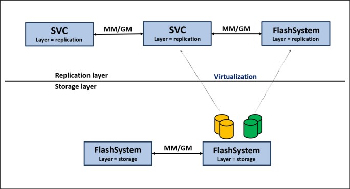
Figure 6-14 Conceptualization of layers
Generally, changing the layer is only performed at initial setup time or as part of a major reconfiguration. To change the layer of an IBM FlashSystem system, the system must meet the following preconditions:
•The IBM FlashSystem system must not have IBM Spectrum Virtualize, Storwize, or FlashSystem host objects defined, and must not be virtualizing any other IBM FlashSystem/Storwize controllers.
•The IBM FlashSystem system must not be visible to any other IBM Spectrum Virtualize, Storwize, or FlashSystem system in the SAN fabric, which might require SAN zoning changes.
•The IBM FlashSystem system must not have any system partnerships defined. If it is already using Metro Mirror or Global Mirror, the existing partnerships and relationships must be removed first.
Changing an IBM FlashSystem system from Storage layer to Replication layer can only be performed by using the CLI. After you are certain that all of the preconditions have been met, issue the following command:
chsystem -layer replication
Partnership topologies
IBM Spectrum Virtualize allows various partnership topologies, as shown in Figure 6-15. Each box represents an IBM Spectrum Virtualize based system.
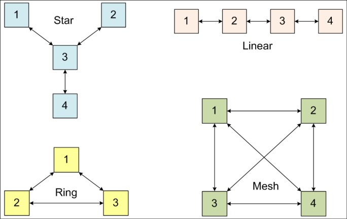
Figure 6-15 Supported topologies for Remote Copy partnerships
The set of systems directly or indirectly connected form the connected set. A system can be partnered with up to three remote systems. No more than four systems can be in the same connected set is allowed.
Star topology
A star topology can be used, for example, to share a centralized disaster recovery system (3, in this example) with up to three other systems, for example replicating 1 → 3, 2 → 3, and 4 → 3.
Ring topology
A ring topology (3 or more systems) can be used to establish a one-in, one-out implementation. For example, the implementation can be 1 → 2, 2 → 3, 3 → 1 to spread replication loads evenly among three systems.
Linear topology
A linear topology of two or more sites is also possible. However, it would generally be simpler to create partnerships between system 1 and system 2, and separately between system 3 and system 4.
Mesh topology
A fully connected mesh topology is where every system has a partnership to each of the three other systems. This topology allows flexibility in that volumes can be replicated between any two systems.
|
Topology considerations: Consider the following points:
•Although systems can have up to three partnerships, any one volume can be part of only a single relationship. That is, you cannot establish a multi-target Remote Copy relationship for a specific volume. However, three-site replication is possible with the introduction of the Spectrum Virtualize 3-site replication. For more information, see IBM Spectrum Virtualize 3-Site Replication, SG24-8504.
•Although various topologies are supported, it is advisable to keep your partnerships as simple as possible, which in most cases mean system pairs or a star.
|
Intrasystem Remote Copy
The Intrasystem Remote Copy feature allows Remote Copy relationships to be created within the same Spectrum Virtualize system. A preconfigured local parthership is created by default in the system for the intrasystem Remote Copy.
Considering that within a single system a Remote Copy does not protect data in a disaster scenarios, this capability has no practical use except for functional testing. For this reason, intrasystem Remote Copy is not officially supported for production data.
Metro Mirror functional overview
Metro Mirror provides synchronous replication. It is designed to ensure that updates are committed to both the primary and secondary volumes before sending an acknowledgment (Ack) of the completion to the server.
If the primary volume fails completely for any reason, Metro Mirror is designed to ensure that the secondary volume holds the same data as the primary did immediately before the failure.
Metro Mirror provides the simplest way to maintain an identical copy on both the primary and secondary volumes. However, as with any synchronous copy over long distance, there can be a performance impact to host applications due to network latency.
Metro Mirror supports relationships between volumes that are up to 300 kilometers (km) apart. Latency is an important consideration for any Metro Mirror network. With typical fiber optic round-trip latencies of 1 millisecond (ms) per 100 km, you can expect a minimum of 3 ms extra latency, due to the network alone, on each I/O if you are running across the 300 km separation.
Figure 6-16 shows the order of Metro Mirror write operations.
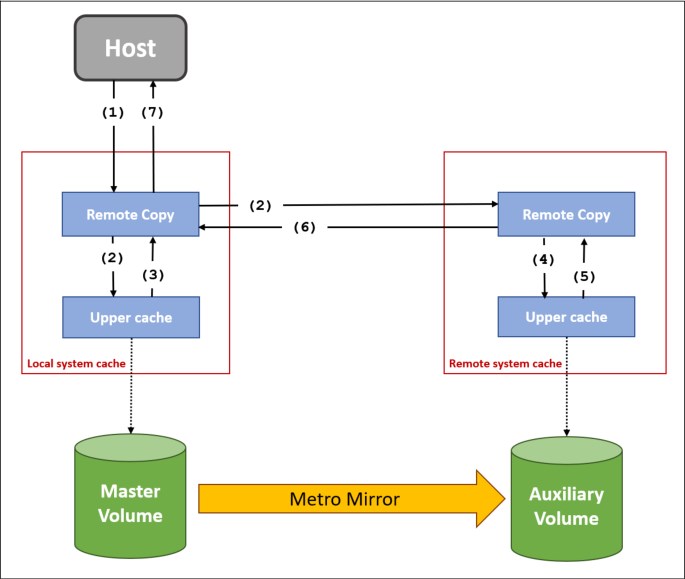
Figure 6-16 Metro Mirror write sequence
The write operation sequence includes the following steps:
1. The write operation is initiated by the host and intercepted by the Remote Copy component of the local system cache.
2. The write operation is simultaneously written in the upper cache component and sent to the remote system.
3. The write operation on local system upper cache is acknowledged back to Remote Copy component on local system.
4. The write operation is written in the upper cache component of the remote system. This operation is initiated as soon as the data arrives from the local system and do not depend on operation ongoing in the local system.
5. The write operation on remote system upper cache is acknowledged back to Remote Copy component on remote system.
6. The remote write operation is acknowledged back to Remote Copy component on local system.
7. The write operation is acknowledged back to the host.
For a write to be considered as committed, it is required that the data is written in both local and remote systems cache. De-staging to disk is a natural part of I/O management, but it is not generally in the critical path for a Metro Mirror write acknowledgment.
Global Mirror functional overview
Global Mirror provides asynchronous replication. It is designed to reduce the dependency on round-trip network latency by acknowledging the primary write in parallel with sending the write to the secondary volume.
If the primary volume fails completely for any reason, Global Mirror is designed to ensure that the secondary volume holds the same data as the primary did at a point a short time before the failure. That short period of data loss is typically 10 ms - 10 seconds, but varies according to individual circumstances.
Global Mirror provides a way to maintain a write-order-consistent copy of data at a secondary site only slightly behind the primary. Global Mirror has minimal impact on the performance of the primary volume.
Although Global Mirror is an asynchronous Remote Copy technique, foreground writes at the local system and mirrored foreground writes at the remote system are not wholly independent of one another. IBM Spectrum Virtualize implementation of Global Mirror uses algorithms to maintain a consistent image at the target volume always.
They achieve this image by identifying sets of I/Os that are active concurrently at the source, assigning an order to those sets, and applying these sets of I/Os in the assigned order at the target. The multiple I/Os within a single set are applied concurrently.
The process that marshals the sequential sets of I/Os operates at the remote system, and therefore is not subject to the latency of the long-distance link.
Figure 6-17 on page 283 shows that a write operation to the master volume is acknowledged back to the host that issues the write before the write operation is mirrored to the cache for the auxiliary volume.

Figure 6-17 Global Mirror relationship write operation
The write operation sequence includes the following steps:
1. The write operation is initiated by the host and intercepted by the Remote Copy component of the local system cache.
2. The Remote Copy component on local system completes the sequence tagging and the write operation is simultaneously written in the upper cache component and sent to the remote system (along with the sequence number).
3. The write operation on local system upper cache is acknowledged back to Remote Copy component on local system.
4. The write operation is acknowledged back to the host.
5. The Remote Copy component on remote system initiates the write operation to the upper cache component according with the sequence number. This operation is initiated as soon as the data arrives from the local system and do not depend on operation ongoing in the local system.
6. The write operation on remote system upper cache is acknowledged back to Remote Copy component on remote system.
7. The remote write operation is acknowledged back to Remote Copy component on local system.
With Global Mirror, a confirmation is sent to the host server before the host receives a confirmation of the completion at the auxiliary volume. The Global Mirror function identifies sets of write I/Os that are active concurrently at the primary volume. It then assigns an order to those sets and applies these sets of I/Os in the assigned order at the auxiliary volume.
Further writes might be received from a host when the secondary write is still active for the same block. In this case, although the primary write might complete, the new host write on the auxiliary volume is delayed until the previous write is completed. Finally, note that any delay in step 2 is reflected in write-delay on primary volume.
Write ordering
Many applications that use block storage are required to survive failures, such as a loss of power or a software crash. They are also required to not lose data that existed before the failure. Because many applications must perform many update operations in parallel to that storage block, maintaining write ordering is key to ensuring the correct operation of applications after a disruption.
An application that performs a high volume of database updates is often designed with the concept of dependent writes. Dependent writes ensure that an earlier write completes before a later write starts. Reversing the order of dependent writes can undermine the algorithms of the application and can lead to problems, such as detected or undetected data corruption.
Colliding writes
Colliding writes are defined as new write I/Os that overlap existing active write I/Os.
The original Global Mirror algorithm required only a single write to be active on any 512-byte LBA of a volume. If another write was received from a host while the auxiliary write was still active, the new host write was delayed until the auxiliary write was complete (although the master write might complete). This restriction was needed if a series of writes to the auxiliary must be retried (which is known as reconstruction). Conceptually, the data for reconstruction comes from the master volume.
If multiple writes were allowed to be applied to the master for a sector, only the most recent write had the correct data during reconstruction. If reconstruction was interrupted for any reason, the intermediate state of the auxiliary was inconsistent.
Applications that deliver such write activity do not achieve the performance that Global Mirror is intended to support. A volume statistic is maintained about the frequency of these collisions. The original Global Mirror implementation has been modified to allow multiple writes to a single location to be outstanding in the Global Mirror algorithm.
A need still exists for master writes to be serialized. The intermediate states of the master data must be kept in a non-volatile journal while the writes are outstanding to maintain the correct write ordering during reconstruction. Reconstruction must never overwrite data on the auxiliary with an earlier version. The colliding writes of volume statistic monitoring are now limited to those writes that are not affected by this change.

Figure 6-18 Colliding writes
The following numbers correspond to the numbers that are shown in Figure 6-18:
1. A first write is performed from the host to LBA X.
2. A host is provided acknowledgment that the write is complete, even though the mirrored write to the auxiliary volume is not yet completed.
The first two actions (1 and 2) occur asynchronously with the first write.
3. A second write is performed from the host to LBA X. If this write occurs before the host receives acknowledgment (2), the write is written to the journal file.
4. A host is provided acknowledgment that the second write is complete.
Global Mirror Change Volumes functional overview
Global Mirror with Change Volumes (GMCV) provides asynchronous replication based on point-in-time copies of data. It is designed to allow for effective replication over lower bandwidth networks and to reduce any impact on production hosts.
Metro Mirror and Global Mirror both require the bandwidth to be sized to meet the peak workload. Global Mirror with Change Volumes must only be sized to meet the average workload across a cycle period.
Figure 6-19 shows a high-level conceptual view of Global Mirror with Change Volumes. GMCV uses FlashCopy to maintain image consistency and to isolate host volumes from the replication process.

Figure 6-19 Global Mirror with Change Volumes
Global Mirror with Change Volumes also only sends one copy of a changed grain that might have been rewritten many times within the cycle period.
If the primary volume fails completely for any reason, GMCV is designed to ensure that the secondary volume holds the same data as the primary did at a specific point in time. That period of data loss is typically between 5 minutes and 24 hours, but varies according to the design choices that you make.
Change Volumes hold point-in-time copies of 256 KB grains. If any of the disk blocks in a grain change, that grain is copied to the change volume to preserve its contents. Change Volumes are also maintained at the secondary site so that a consistent copy of the volume is always available even when the secondary volume is being updated.
Primary and Change Volumes are always in the same I/O group and the Change Volumes are always thin-provisioned. Change Volumes cannot be mapped to hosts and used for host I/O, and they cannot be used as a source for any other FlashCopy or Global Mirror operations.
Figure 6-20 on page 287 shows how a Change Volume is used to preserve a point-in-time data set, which is then replicated to a secondary site. The data at the secondary site is in turn preserved by a Change Volume until the next replication cycle has completed.
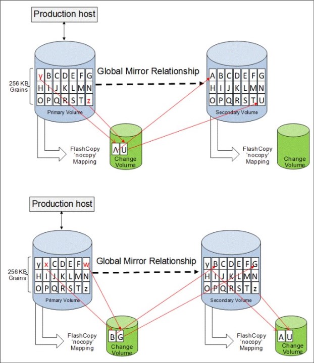
Figure 6-20 Global Mirror with Change Volumes uses FlashCopy point-in-time copy technology
|
FlashCopy mapping note: These FlashCopy mappings are not standard FlashCopy volumes and are not accessible for general use. They are internal structures that are dedicated to supporting Global Mirror with Change Volumes.
|
The options for -cyclingmode are none and multi.
Specifying or taking the default none means that Global Mirror acts in its traditional mode without Change Volumes.
Specifying multi means that Global Mirror starts cycling based on the cycle period, which defaults to 300 seconds. The valid range is from 60 seconds to 24*60*60 seconds
(86,400 seconds = one day).
(86,400 seconds = one day).
If all of the changed grains cannot be copied to the secondary site within the specified time, then the replication is designed to take as long as it needs and to start the next replication as soon as the earlier one completes. You can choose to implement this approach by deliberately setting the cycle period to a short amount of time, which is a perfectly valid approach. However, remember that the shorter the cycle period, the less opportunity there is for peak write I/O smoothing, and the more bandwidth you need.
The -cyclingmode setting can only be changed when the Global Mirror relationship is in a stopped state.
Recovery point objective using Change Volumes
RPO is the maximum tolerable period in which data might be lost if you switch over to your secondary volume.
If a cycle completes within the specified cycle period, then the RPO is not more than 2x cycle long. However, if it does not complete within the cycle period, then the RPO is not more than the sum of the last two cycle times.
The current RPO can be determined by looking at the lsrcrelationship freeze time attribute. The freeze time is the time stamp of the last primary Change Volume that has completed copying to the secondary site. Note the following example:
1. The cycle period is the default of 5 minutes and a cycle is triggered at 6:00 AM. At 6:03 AM, the cycle completes. The freeze time would be 6:00 AM, and the RPO is 3 minutes.
2. The cycle starts again at 6:05 AM. The RPO now is 5 minutes. The cycle is still running at 6:12 AM, and the RPO is now up to 12 minutes because 6:00 AM is still the freeze time of the last complete cycle.
3. At 6:13 AM, the cycle completes and the RPO now is 8 minutes because 6:05 AM is the freeze time of the last complete cycle.
4. Because the cycle period has been exceeded, the cycle immediately starts again.
6.3.3 Remote Copy network planning
Remote Copy partnerships and relationships do not work reliably if the connectivity on which they are running is configured incorrectly. This section focuses on the inter-system network, giving an overview of the remote system connectivity options.
Terminology
The inter-system network is specified in terms of latency and bandwidth. These parameters define the capabilities of the link regarding the traffic that is on it. They be must be chosen so that they support all forms of traffic, including mirrored foreground writes, background copy writes, and inter-system heartbeat messaging (node-to-node communication).
Link latency is the time that is taken by data to move across a network from one location to another and is measured in milliseconds. The latency measures the time spent to send the data and to receive the acknowledgment back (Round Trip Time - RTT).
Link bandwidth is the network capacity to move data as measured in millions of bits per second (Mbps) or billions of bits per second (Gbps).
The term bandwidth is also used in the following context:
•Storage bandwidth: The ability of the back-end storage to process I/O. Measures the amount of data (in bytes) that can be sent in a specified amount of time.
•Remote Copy partnership bandwidth (parameter): The rate at which background write synchronization is attempted (unit of MBps).
inter-system connectivity supports mirrored foreground and background I/O. A portion of the link is also used to carry traffic that is associated with the exchange of low-level messaging between the nodes of the local and remote systems. A dedicated amount of the link bandwidth is required for the exchange of heartbeat messages and the initial configuration of inter-system partnerships.
Fibre Channel connectivity is the standard connectivity that is used for the Remote Copy inter-system networks. It uses the FC protocol and SAN infrastructures to interconnect the systems.
Native IP connectivity is a connectivity option based on standard TPC/IP infrastructures provided by IBM Spectrum Virtualize technology.
Standard SCSI operations and latency
A single SCSI read operation over a Fibre Channel network is shown in Figure 6-21.

Figure 6-21 Standard SCSI read operation
The initiator starts by sending a read command (FCP_CMND) across the network to the target. The target is responsible to retrieve the data and to respond sending the data (FCP_DATA_OUT) to the initiator. Finally, the target completes the operation sending the command completed response (FCP_RSP). Note that FCP_DATA_OUT and FCP_RSP are sent to the initiator in sequence. Overall, one round trip is required to complete the read; therefore, the read takes at least one RTT, plus the time for the data out.
Typical SCSI behavior for a write is shown in Figure 6-22.

Figure 6-22 Standard SCSI write operation
A standard-based SCSI write is a two-step process:
1. The write command (FCP_CMND) is sent across the network to the target. The first round trip is essentially asking transfer permission from the target. The target responds with an acceptance (FCP_XFR_RDY).
The initiator waits until it receives a response from the target before starting the second step; that is, sending the data (FCP_DATA_OUT).
2. The target completes the operation y sending the command completed response (FCP_RSP). Overall, two round trips are required to complete the write; therefore, the write takes at least 2 × RTT, plus the time for the data out.
Within the confines of a data center, where the latencies are measured in microseconds (μsec), no issues exist. However, across a geographical network where the latencies are measured in milliseconds (ms), the overall service time can be significantly affected.
Considering that the network delay over fiber optics per kilometer (km) is approximately 5 μsec (10 μsec RTT), the resulting minimum service time per every km of distance for a SCSI operation is 10 μsec and 20 μsec for reads and writes respectively; for example, a SCSI write over 50 km has a minimum service time of 1000 μsec (that is, 1ms).
IBM Spectrum Virtualize remote write operations
With the standard SCSI operations, the writes are especially affected by the latency. IBM Spectrum Virtualize implements a proprietary protocol to mitigate the effects of the latency in the write operations over a FC network.
Figure 6-23 shows how a remote copy write operation is performed over a Fibre Channel network.
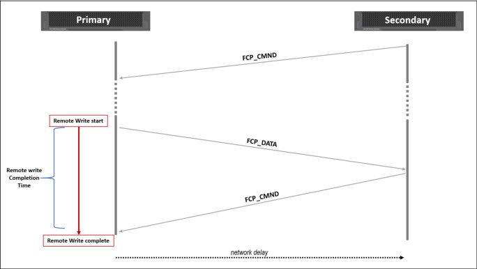
Figure 6-23 Spectrum Virtualize remote copy write
When the remote copy is initialized, the target system (secondary system) sends a dummy read command (FCP_CMND) to the initiator (primary system). This command waits on the initiator until a write operation is requested.
When a write operation is started, the data is sent to the target as response of the dummy read command (FCP_DATA_OUT). Finally, the target completes the operation by sending a new dummy read command (FCP_CMND).
Overall, one round trip is required to complete the remote write using this protocol; therefore, replicating a write takes at least one RTT plus the time for the data out.
Network latency considerations
The maximum supported round-trip latency between sites depends on the type of partnership between systems. Table 6-6 lists the maximum round-trip latency. This restriction applies to all variants of remote mirroring.
Table 6-6 Maximum round trip
|
Partnership
| ||
|
FC
|
1 Gbps IP
|
10 Gbps IP
|
|
250 ms
|
80 ms
|
10 ms
|
More configuration requirements and guidelines apply to systems that perform remote mirroring over extended distances, where the round-trip time is greater than 80 ms. If you use remote mirroring between systems with 80 - 250 ms round-trip latency, you must meet the following additional requirements:
•The RC buffer size setting must be 512 MB on each system in the partnership. This setting can be accomplished by running the chsystem -rcbuffersize 512 command on each system.
|
Important: Changing this setting is disruptive to Metro Mirror and Global Mirror operations. Use this command only before partnerships are created between systems, or when all partnerships with the system are stopped.
|
•Two FC ports on each node that will be used for replication must be dedicated for replication traffic. This configuration can be achieved by using SAN zoning and port masking.
•SAN zoning should be applied to provide separate intrasystem zones for each local-remote I/O group pair that is used for replication. For more information about zoning guidelines, see “Remote system ports and zoning considerations” on page 298.
Link bandwidth that is used by internode communication
IBM Spectrum Virtualize uses part of the bandwidth for its internal inter-system heartbeat. The amount of traffic depends on how many nodes are in each of the local and remote systems. Table 6-7 shows the amount of traffic (in megabits per second) that is generated by different sizes of systems.
Table 6-7 IBM Spectrum Virtualize inter-system heartbeat traffic (megabits per second)
|
Local or remote system
|
Two nodes
|
Four nodes
|
Six nodes
|
Eight nodes
|
|
Two nodes
|
5
|
6
|
6
|
6
|
|
Four nodes
|
6
|
10
|
11
|
12
|
|
Six nodes
|
6
|
11
|
16
|
17
|
|
Eight nodes
|
6
|
12
|
17
|
21
|
These numbers represent the total traffic between the two systems when no I/O is occurring to a mirrored volume on the remote system. Half of the data is sent by one system, and half of the data is sent by the other system. The traffic is divided evenly over all available connections. Therefore, if you have two redundant links, half of this traffic is sent over each link during fault-free operation.
If the link between the sites is configured with redundancy to tolerate single failures, size the link so that the bandwidth and latency statements continue to be accurate even during single failure conditions.
Network sizing considerations
Proper network sizing is essential for the Remote Copy services operations. Failing to estimate the network sizing requirements can lead to poor performance in Remote Copy services and the production workload.
Consider that inter-system bandwidth should be capable of supporting the combined traffic of the following items:
•Mirrored foreground writes, as generated by your server applications at peak times
•Background write synchronization, as defined by the Global Mirror bandwidth parameter
•inter-system communication (heartbeat messaging)
Calculating the required bandwidth is essentially a question of mathematics based on your current workloads, so you should start by assessing your current workloads.
Metro Mirror and Global Mirror network sizing
With the Metro Mirror, due to its synchronous nature, the amount of replication bandwidth required to mirror a given foreground write-data throughput is not less than the foreground write-data throughput.
The Global Mirror, not having write buffering resources, tends to mirror the foreground write as soon as it is committed in cache and therefore the bandwidth requirements are similar to the Metro Mirror.
For a proper bandwidth sizing with Metro or Global Mirror, you must know your peak write workload to at least a five-minute interval. This information can be easily gained from tools like IBM Spectrum Control. Finally, you need to allow for the background copy, intercluster communication traffic, and a safe margin for unexpected peaks and workload growth.
|
Recommendation: Do not compromise on bandwidth or network quality when planning a Metro or Global Mirror deployment. If bandwidth is likely to be an issue in your environment, consider GMCV.
|
As an example, consider a business with the following I/O profile:
•The average write size is 8 KB (= 8 x 8 bits/1024 = 0.0625 Mb).
•For most of the day between 8 AM and 8 PM, the write activity is approximately 1500 writes per second.
•Twice a day (once in the morning and once in the afternoon), the system bursts up to 4500 writes per second for up to 10 minutes.
This example represents a general traffic pattern that might be common in many medium-sized sites. Furthermore, 20% of bandwidth must be left available for the background synchronization.
Metro Mirror or Global Mirror require bandwidth on the instantaneous peak of 4500 writes per second as follows:
4500 x 0.0625 = 282 Mbps + 20% resync allowance + 5 Mbps heartbeat = 343 Mbps dedicated plus any safety margin plus growth
GMCV network sizing
The GMCV is typically less demanding in terms of bandwidth requirements for a number of reasons.
First, by using its journaling capabilities, the GMCV provides a way to maintain point-in-time copies of data at a secondary site where insufficient bandwidth is available to replicate the peak workloads in real time.
Another factor that can reduce the bandwidth that is required for GMCV is that it only sends one copy of a changed grain, which might have been rewritten many times within the cycle period.
The GMCV network sizing is basically a trade-off between RPO, journal capacity, and network bandwidth. A direct relationship exists between the RPO and the physical occupancy of the change volumes: the lower the RPO, the less capacity is used by change volumes. However, higher RPO requires usually less network bandwidth.
For a proper bandwidth sizing with GMCV, you need to know your average write workload during the cycle time. This information can be easily gained from tools like IBM Spectrum Control. Finally, you need to allow for the background resync workload, intercluster communication traffic, and a safe margin for unexpected peaks and workload growth.
Consider the following sizing exercises:
•GMCV peak 30-minute cycle time
If we look at this time broken into 10-minute periods, the peak 30-minute period is made up of one 10-minute period of 4500 writes per second, and two 10-minute periods of 1500 writes per second. The average write rate for the 30-minute cycle period can then be expressed mathematically as follows:
(4500 + 1500 + 1500) / 3 = 2500 writes/sec for a 30-minute cycle period
The minimum bandwidth that is required for the cycle period of 30 minutes is as follows:
2500 x 0.0625 = 157 Mbps + 20% resync allowance + 5 Mbps heartbeat = 195 Mbps dedicated plus any safety margin plus growth
•GMCV peak 60-minute cycle time
For a cycle period of 60 minutes, the peak 60-minute period is made up of one 10-minute period of 4500 writes per second, and five 10-minute periods of 1500 writes per second. The average write for the 60-minute cycle period can be expressed as follows:
(4500 + 5 x 1500) replicating until 8 AM at the latest would probably require at least the following bandwidth:
(9000 + 70 x 1500) / 72 = 1584 x 0.0625 = 99 Mbps + 100% + 5 Mbps heartbeat = 203 Mbps at night plus any safety margin plus growth, non-dedicated, time-shared with daytime traffic
The central principle of sizing is that you need to know your write workload:
•For Metro Mirror and Global Mirror, you need to know the peak write workload.
•For GMCV, you need to know the average write workload.
|
GMCV bandwidth: In the above samples, the bandwidth estimation for the GMCV is based on the assumption that the write operations occurs in such a way that a change volume grain (that has a size of 256 KB) is completely changed before it is transferred to the remote site. In the real life, this situation is unlikely to occur.
Usually only a portion of a grain is changed during a GMCV cycle, but the transfer process always copies the whole grain to the remote site. This behavior can lead to an unforeseen processor burden in the transfer bandwidth that, in the edge case, can be even higher than the one required for a standard Global Mirror.
|
Global Mirror and GMCV coexistence considerations
Global Mirror and GMCV relationships can be defined in the same system. With these configurations, particular attention must be paid to bandwidth sizing and the partnership settings.
The two Global Mirror technologies, as previously described, use the available bandwidth in different ways:
•Regular Global Mirror uses the amount of bandwidth needed to sustain the write workload of the replication set.
•The GMCV uses the fixed amount of bandwidth as defined in the partnership as background copy.
For this reason, during GMCV cycle-creation, a fixed part of the bandwidth is allocated for the background copy and only the remaining part of the bandwidth is available for Global Mirror. To avoid bandwidth contention, which can lead to a 1920 error (see 6.3.6, “1920 error” on page 316) or delayed GMCV cycle creation, the bandwidth must be sized to consider both requirements.
Ideally, in these cases the bandwidth should be enough to accommodate the peak write workload for the Global Mirror replication set plus the estimated bandwidth needed to fulfill the RPO of GMCV. If these requirements cannot be met due to bandwidth restrictions, the least impacting option is to increase the GMCV cycle period and then reduce the background copy rate to minimize the chance of a 1920 error.
Note that these considerations also apply to configurations where multiple IBM Spectrum Virtualize based systems are sharing the same bandwidth resources.
Fibre Channel connectivity
When you use FC technology for the inter-system network, consider the following items:
•Hops
Redundancy
The inter-system network must adopt the same policy toward redundancy as for the local and remote systems to which it is connecting. The ISLs must have redundancy, and the individual ISLs must provide the necessary bandwidth in isolation.
Basic topology and problems
Because of the nature of FC, you must avoid ISL congestion whether within individual SANs or across the inter-system network. Although FC (and IBM FlashSystem system) can handle an overloaded host or storage array, the mechanisms in FC are ineffective for dealing with congestion in the fabric in most circumstances. The problems that are caused by fabric congestion can range from dramatically slow response time to storage access loss. These issues are common with all high-bandwidth SAN devices and are inherent to FC. They are not unique to the IBM Spectrum Virtualize products.
When an FC network becomes congested, the FC switches stop accepting more frames until the congestion clears. They can also drop frames. Congestion can quickly move upstream in the fabric and clog the end devices from communicating anywhere.
This behavior is referred to as head-of-line blocking. Although modern SAN switches internally have a nonblocking architecture, head-of-line-blocking still exists as a SAN fabric problem. Head-of-line blocking can result in IBM FlashSystem canisters that cannot mirror their write caches because you have a single congested link that leads to an edge switch.
Distance extensions options
To implement remote mirroring over a distance by using the FC, you have the following choices:
•Optical multiplexors, such as dense wavelength division multiplexing (DWDM) or coarse wavelength division multiplexing (CWDM) devices.
Optical multiplexors can extend a SAN up to hundreds of kilometers (or miles) at high speeds. For this reason, they are the preferred method for long-distance expansion. If you use multiplexor-based distance extensions, closely monitor your physical link error counts in your switches. Optical communication devices are high-precision units. When they shift out of calibration, you will start to see errors in your frames.
•Long-distance Small Form-factor Pluggable (SFP) transceivers and XFPs.
Long-distance optical transceivers have the advantage of extreme simplicity. You do not need expensive equipment, and only a few configuration steps need to be performed. However, ensure that you use only transceivers that are designed for your particular SAN switch.
•Fibre Channel-to-IP conversion boxes. FC over IP (FCIP) is, by far, the most common and least expensive form of distance extension. It is also complicated to configure. Relatively subtle errors can have severe performance implications.
With IP-based distance extension, you must dedicate bandwidth to your FCIP traffic if the link is shared with other IP traffic. Do not assume that because the link between two sites has low traffic or is used only for email, this type of traffic is always the case. FC is far more sensitive to congestion than most IP applications.
Also, when you are communicating with the networking architects for your organization, make sure to distinguish between megabytes per second as opposed to megabits per second. In the storage world, bandwidth is often specified in megabytes per second (MBps), and network engineers specify bandwidth in megabits per second (Mbps).
Of these options, the optical distance extension is the preferred method. IP distance extension introduces more complexity, is less reliable, and has performance limitations. However, optical distance extension can be impractical in many cases because of cost or unavailability.
For more information about supported SAN routers and FC extenders, see this IBM Documentation web page.
Hops
The hop count is not increased by the intersite connection architecture. For example, if you have a SAN extension that is based on DWDM, the DWDM components are not apparent to the number of hops. The hop count limit within a fabric is set by the fabric devices (switch or director) operating system. It is used to derive a frame hold time value for each fabric device.
This hold time value is the maximum amount of time that a frame can be held in a switch before it is dropped, or the fabric is busy condition is returned. For example, a frame might be held if its destination port is unavailable. The hold time is derived from a formula that uses the error detect timeout value and the resource allocation timeout value. It is considered that every extra hop adds about 1.2 microseconds of latency to the transmission.
Currently, IBM FlashSystem copy services support three hops when protocol conversion exists. Therefore, if you have DWDM extended between primary and secondary sites, three SAN directors or switches can exist between the primary and secondary systems.
Buffer credits
SAN device ports need memory to temporarily store frames as they arrive, assemble them in sequence, and deliver them to the upper layer protocol. The number of frames that a port can hold is called its buffer credit. FC architecture is based on a flow control that ensures a constant stream of data to fill the available pipe.
When two FC ports begin a conversation, they exchange information about their buffer capacities. An FC port sends only the number of buffer frames for which the receiving port gives credit. This method avoids overruns and provides a way to maintain performance over distance by filling the pipe with in-flight frames or buffers.
The following types of transmission credits are available:
•Buffer_to_Buffer Credit
During login, N_Ports and F_Ports at both ends of a link establish its Buffer to Buffer Credit (BB_Credit).
•End_to_End Credit
In the same way during login, all N_Ports establish End-to-End Credit (EE_Credit) with each other. During data transmission, a port must not send more frames than the buffer of the receiving port can handle before you receive an indication from the receiving port that it processed a previously sent frame. Two counters are used: BB_Credit_CNT and EE_Credit_CNT. Both counters are initialized to zero during login.
|
FC Flow Control: Each time that a port sends a frame, it increments BB_Credit_CNT and EE_Credit_CNT by one. When it receives R_RDY from the adjacent port, it decrements BB_Credit_CNT by one. When it receives ACK from the destination port, it decrements EE_Credit_CNT by one.
At any time, if BB_Credit_CNT becomes equal to the BB_Credit, or EE_Credit_CNT becomes equal to the EE_Credit of the receiving port, the transmitting port stops sending frames until the respective count is decremented.
|
The previous statements are true for Class 2 service. Class 1 is a dedicated connection. Therefore, BB_Credit is not important, and only EE_Credit is used (EE Flow Control). However, Class 3 is an unacknowledged service. Therefore, it uses only BB_Credit (BB Flow Control), but the mechanism is the same in all cases.
The number of buffers is an important factor in overall performance. You need enough buffers to ensure that the transmitting port can continue to send frames without stopping to use the full bandwidth, which is true with distance. The total amount of buffer credit needed to optimize the throughput depends on the link speed and the average frame size.
For example, consider an 8 Gbps link connecting two switches that are 100 km apart. At 8 Gbps, a full frame (2148 bytes) occupies about 0.51 km of fiber. In a 100 km link, you can send 198 frames before the first one reaches its destination. You need an ACK to go back to the start to fill EE_Credit again. You can send another 198 frames before you receive the first ACK.
You need at least 396 buffers to allow for nonstop transmission at 100 km distance. The maximum distance that can be achieved at full performance depends on the capabilities of the FC node that is attached at either end of the link extenders, which are vendor-specific. A match should occur between the buffer credit capability of the nodes at either end of the extenders.
Remote system ports and zoning considerations
Ports and zoning requirements for the remote system partnership have changed over time.
The current preferred configuration is based on the information that is available at this IBM Support web page.
The preferred practice for the IBM FlashSystem systems is to provision dedicated node ports for local node-to-node traffic (by using port masking) and isolate Global Mirror node-to-node traffic between the local nodes from other local SAN traffic.
|
Remote port masking: To isolate the node-to-node traffic from the Remote Copy traffic, the local and remote port masking implementation is preferable.
|
This configuration of local node port masking is less of a requirement on non-clustered IBM FlashSystem systems, where traffic between node canisters in an I/O group is serviced by the dedicated PCI inter-canister link in the enclosure. The following guidelines apply to the remote system connectivity:
•The minimum requirement to establish a Remote Copy partnership is to connect at least one node per system. When remote connectivity among all the nodes of both systems is not available, the nodes of the local system not participating to the remote partnership will use the node/nodes defined in the partnership as a bridge to transfer the replication data to the remote system.
This replication data transfer occurs through the node-to-node connectivity. Note that this configuration, even though supported, allows the replication traffic to go through the node-to-node connectivity and this is not recommended.
•Partnered systems should use the same number of nodes in each system for replication.
•For maximum throughput, all nodes in each system should be used for replication, both in terms of balancing the preferred node assignment for volumes and for providing inter-system FC connectivity.
•Where possible, use the minimum number of partnerships between systems. For example, assume site A contains systems A1 and A2, and site B contains systems B1 and B2. In this scenario, creating separate partnerships between pairs of systems (such as A1-B1 and A2-B2) offers greater performance for Global Mirror replication between sites than a configuration with partnerships defined between all four systems.
For zoning, the following rules for the remote system partnership apply:
•For Remote Copy configurations where the round-trip latency between systems is less than 80 milliseconds, zone two FC ports on each node in the local system to two FC ports on each node in the remote system.
•For Remote Copy configurations where the round-trip latency between systems is more than 80 milliseconds, apply SAN zoning to provide separate intrasystem zones for each local-remote I/O group pair that is used for replication, as shown in Figure 6-24.

Figure 6-24 Zoning scheme for >80 ms Remote Copy partnerships
|
NPIV: IBM FlashSystem systems with the NPIV feature enabled provide virtual WWPN for the host zoning. Those WWPNs are intended for host zoning only and cannot be used for the Remote Copy partnership.
|
SAN Extension design considerations
Disaster Recovery solutions based on Remote Copy technologies require reliable SAN extensions over geographical links. In order to avoid single points of failure, multiple physical links are usually implemented. When implementing these solutions, particular attention must be paid in the Remote Copy network connectivity set up.
Consider a typical implementation of a Remote Copy connectivity using ISLs, as shown in Figure 6-25 on page 300.

Figure 6-25 Typical Remote Copy network configuration
In the configuration that is shown in Figure 6-25, the Remote Copy network is isolated in a Replication SAN that interconnects Site A and Site B through a SAN extension infrastructure using of two physical links. Assume that, for redundancy reasons, two ISLs are used for each fabric for the Replication SAN extension.
There are two possible configurations to interconnect the Replication SANs. In Configuration 1, as shown in Figure 6-26, one ISL per fabric is attached to each physical link through xWDM or FCIP routers. In this case, the physical paths Path A and Path B are used to extend both fabrics.
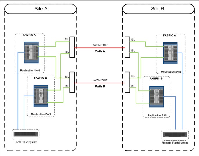
Figure 6-26 Configuration 1: physical paths shared among the fabrics
In Configuration 2, shown in Figure 6-27, ISLs of fabric A are attached only to Path A, while ISLs of fabric B are attached only to Path B. In this case the physical paths are not shared between the fabrics.
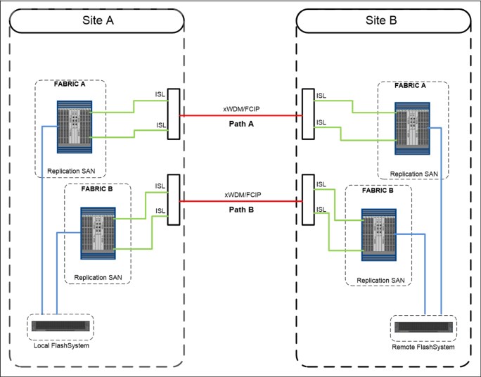
Figure 6-27 Configuration 2: physical paths not shared among the fabrics
With Configuration 1, in case of failure of one of the physical paths, both fabrics are simultaneously affected and a fabric reconfiguration occurs because of an ISL loss. This situation could lead to a temporary disruption of the Remote Copy communication and, in the worst case, to partnership loss condition. To mitigate this situation, link aggregation features like Brocade ISL trunking can be implemented.
With Configuration 2, a physical path failure leads to a fabric segmentation of one of the two fabrics, leaving the other fabric unaffected. In this case, the Remote Copy communication would be guaranteed through the unaffected fabric.
Summarizing, the recommendation is to fully understand the implication of a physical path or xWDM/FCIP router loss in the SAN extension infrastructure and to implement the appropriate architecture to avoid a simultaneous impact.
6.3.4 Remote Copy services planning
When you plan for Remote Copy services, you must keep in mind the considerations that are outlined in the following sections.
Remote Copy configurations limits
To plan for and implement Remote Copy services, you must check the configuration limits and adhere to them. Table 6-8 shows the limits for a system that currently apply to IBM FlashSystem V8.4. Check the online documentation as these limits can change over time.
Table 6-8 Remote Copy maximum limits
|
Remote copy property
|
Maximum
|
Comment
|
|
Remote Copy (Metro Mirror and Global Mirror) relationships per
system
|
10000
|
This configuration can be any mix of Metro Mirror and Global Mirror relationships.
|
|
Active-Active Relationships
|
2000
|
This is the limit for the number of HyperSwap volumes in a system.
|
|
Remote Copy relationships per consistency group
|
None
|
No limit is imposed beyond the Remote Copy relationships per system limit. Apply to Global Mirror and Metro Mirror.
|
|
GMCV relationships per consistency group
|
200
|
|
|
Remote Copy consistency groups per system
|
256
|
|
|
Total Metro Mirror and Global Mirror volume capacity per I/O group
|
2048 TB
|
This limit is the total capacity for all master and auxiliary volumes in the I/O group.
|
|
Total number of Global Mirror with Change Volumes relationships per system
|
256
|
60s cycle time.
|
|
2500
|
300s cycle time.
|
Similar to FlashCopy, the Remote Copy services require memory to allocate the bitmap structures used to track the updates while volume are suspended or synchronizing. The default amount of memory for Remote Copy services is 20 MB. This value can be increased or decreased by using the chiogrp command. The maximum amount of memory that can be specified for Remote Copy services is 512 MB. The grain size for the Remote Copy services is 256 KB.
Remote Copy general restrictions
To use Metro Mirror and Global Mirror, you must adhere to the following rules:
•You must have the same size for source and target volume when defining a Remote Copy relationship. However, the target volume can be a different type (image, striped, or sequential mode) or have different cache settings (cache-enabled or cache-disabled).
•You cannot move Remote Copy source or target volumes to different I/O groups.
•Remote Copy volumes can be resized with the following restrictions:
– Resizing applies to Metro Mirror and Global Mirror only. GMCV is not supported.
– The Remote Copy Consistency Protection feature is not allowed and must be removed before resizing the volumes.
– The Remote Copy relationship must be in synchronized status.
– The resize order must ensure that the target volume always is larger than the source volume.
|
Note: The volume expansion for Metro and Global Mirror volumes was introduced with Spectrum Virtualize version 7.8.1 with some restrictions:
•In the first implementation (up to version 8.2.1), only thin provisioned or compressed volumes were supported.
•With version 8.2.1 also non-mirrored fully allocated volumes were supported.
•With version 8.4 all the restrictions on volume type have been removed.
|
•You can mirror intrasystem Metro Mirror or Global Mirror only between volumes in the same I/O group.
|
Intrasystem remote copy: The intrasystem Global Mirror is not supported on IBM Spectrum Virtualize based systems running version 6 or later.
|
•Global Mirror is not recommended for cache-disabled volumes that are participating in a Global Mirror relationship.
Changing the Remote Copy type
Changing the Remote Copy type for an existing relationship is an easy task. It is enough to stop the relationship, if it is active, and change the properties to set the new Remote Copy type. Remember to create the change volumes in case of change from Metro or Global Mirror to GMCVs.
Interaction between Remote Copy and FlashCopy
Remote Copy functions can be used in conjunction with the FlashCopy function so that you can have both operating concurrently on the same volume. The possible combinations between Remote Copy and FlashCopy follow:
•Remote Copy source:
– A Remote Copy source can be a FlashCopy source.
– A Remote Copy source can be a FlashCopy target with the following restrictions:
• A FlashCopy target volume cannot be updated while it is the source volume of a Metro or Global Mirror relationship that is actively mirroring. A FlashCopy mapping cannot be started while the target volume is in an active Remote Copy relationship.
• The I/O group for the FlashCopy mappings must be the same as the I/O group for the FlashCopy target volume (that is the I/O group of the Remote Copy source).
•Remote Copy target:
– A Remote Copy target can be a FlashCopy source.
– A Remote Copy target can be a FlashCopy target with the following restriction: A FlashCopy mapping must be in the idle_copied state when its target volume is the target volume of an active Metro Mirror or Global Mirror relationship.
When implementing FlashCopy functions for volumes in GMCV relationships, FlashCopy multi-target mappings are created. As described in “Interaction and dependency between Multiple Target FlashCopy mappings” on page 259, this results in dependent mappings that can affect the cycle formation due to the cleaning process. For more information, see “Cleaning process and Cleaning Rate” on page 270.
With such configurations, it is recommended to set the Cleaning Rate accordingly. This recommendation applies also to Consistency Protection volumes and HyperSwap configurations.
Native back-end controller copy functions considerations
As previously discussed, the IBM FlashSystem technology provides a widespread set of copy services functions that cover most of the clients requirements.
However, some storage controllers can provide specific copy services capabilities not available with the current version of IBM Spectrum Virtualize software. The IBM FlashSystem technology addresses these situations by using cache-disabled image mode volumes that virtualize LUN participating to the native back-end controller’s copy services relationships.
Keeping the cache disabled guarantees data consistency throughout the I/O stack, from the host to the back-end controller. Otherwise, by leaving the cache enabled on a volume, the underlying controller does not receive any write I/Os as the host writes them. IBM FlashSystem caches them and processes them later. This process can have more ramifications if a target host depends on the write I/Os from the source host as they are written.
|
Note: Native copy services are not supported on all storage controllers. For more information about the known limitations, see this IBM Support web page.
|
As part of its copy services function, the storage controller might take a LUN offline or suspend reads or writes. IBM FlashSystem does not recognize why this happens. Therefore, it might log errors when these events occur. For this reason, if the IBM FlashSystem must detect the LUN, ensure that the LUN remains in the unmanaged state until full access is granted.
Native back-end controller copy services can also be used for LUNs that are not managed by the IBM FlashSystem. Note that accidental incorrect configurations of the back-end controller copy services involving IBM FlashSystem attached LUN can produce unpredictable results.
For example, if you accidentally use a LUN with IBM FlashSystem data on it as a point-in-time target LUN, you can corrupt that data. Moreover, if that LUN was a managed disk in a managed-disk group with striped or sequential volumes on it, the managed disk group might be brought offline. This situation, in turn, makes all the volumes that belong to that group go offline, leading to a widespread host access disruption.
Remote Copy and code upgrade considerations
When you upgrade system software where the system participates in one or more inter-system relationships, upgrade only one cluster at a time. That is, do not upgrade the systems concurrently.
|
Attention: Upgrading both systems concurrently is not monitored by the software upgrade process.
|
Allow the software upgrade to complete one system before it is started on the other system. Upgrading both systems concurrently can lead to a loss of synchronization. In stress situations, it can further lead to a loss of availability.
Usually, pre-existing Remote Copy relationships are unaffected by a software upgrade that is performed correctly. However, always check in the target code release notes for special considerations on the copy services.
Although it is not a best practice, a Remote Copy partnership can be established, with some restrictions, among systems with different IBM Spectrum Virtualize versions. For more information, see this IBM Support web page.
Volume placement considerations
You can optimize the distribution of volumes within I/O groups at the local and remote systems to maximize performance.
Although defined at a system level, the partnership bandwidth and consequently the background copy rate) is evenly divided among the cluster’s I/O groups. The available bandwidth for the background copy can be used by either canister or shared by both canisters within the I/O Group.
This bandwidth allocation is independent from the number of volumes for which a canister is responsible. Each node, in turn, divides its bandwidth evenly between the (multiple) Remote Copy relationships with which it associates volumes that are performing a background copy.
Volume preferred node
Conceptually, a connection (path) goes between each node on the primary system to each node on the remote system. Write I/O, which is associated with remote copying, travels along this path. Each node-to-node connection is assigned a finite amount of Remote Copy resource and can sustain only in-flight write I/O to this limit.
The node-to-node in-flight write limit is determined by the number of nodes in the remote system. The more nodes that exist at the remote system, the lower the limit is for the in-flight write I/Os from a local node to a remote node. That is, less data can be outstanding from any one local node to any other remote node. Therefore, to optimize performance, Global Mirror volumes must have their preferred nodes distributed evenly between the nodes of the systems.
The preferred node property of a volume helps to balance the I/O load between nodes in that I/O group. This property is also used by Remote Copy to route I/O between systems.
The IBM FlashSystem canister that receives a write for a volume is normally the preferred node of the volume. For volumes in a Remote Copy relationship, that node is also responsible for sending that write to the preferred node of the target volume. The primary preferred node is also responsible for sending any writes that relate to the background copy. Again, these writes are sent to the preferred node of the target volume.
Each node of the remote system has a fixed pool of Remote Copy system resources for each node of the primary system. That is, each remote node has a separate queue for I/O from each of the primary nodes. This queue is a fixed size and is the same size for every node. If preferred nodes for the volumes of the remote system are set so that every combination of primary node and secondary node is used, Remote Copy performance is maximized.
Figure 6-28 on page 307 shows an example of Remote Copy resources that are not optimized. Volumes from the local system are replicated to the remote system. All volumes with a preferred node of Node 1 are replicated to the remote system, where the target volumes also have a preferred node of Node 1.

Figure 6-28 Remote Copy resources that are not optimized
With the configuration that is shown in Figure 6-28, the resources for remote system Node 1 that are reserved for local system Node 2 are not used. Also, the resources for local system Node 1 that are reserved for remote system Node 2 are not used.
If the configuration that is shown in Figure 6-28 changes to the configuration that is shown in Figure 6-29, all Remote Copy resources for each node are used, and Remote Copy operates with better performance.

Figure 6-29 Optimized Global Mirror resources
GMCV Change Volumes placement considerations
The Change Volumes in a GMCV configuration are thin-provisioned volumes that are used as FlashCopy targets. For this reason the same considerations apply that are described in “Volume placement considerations” on page 267. The Change Volumes can be compressed to reduce the amount of space used; however, it is important to note that the Change Volumes might be subject to heavy write workload both in the primary and secondary system.
Therefore, the placement on the back-end is critical to provide adequate performances. Consider to use DRP for the change volumes only if beneficial in terms of space savings.
|
Trick: The internal FlashCopy used by the GMCV is with 256KB grain size. However, it is possible to force a 64KB grain size by creating a FlashCopy with 64KB grain size from the GMCV volume and a dummy target volume before assigning the change volume to the relationship. This can be done to both source and target volumes. After the CV assignment is done, the dummy FlashCopy can be deleted.
|
Background copy considerations
The Remote Copy partnership bandwidth parameter explicitly defines the rate at which the background copy is attempted, but also implicitly affects foreground I/O. Background copy bandwidth can affect foreground I/O latency in one of the following ways:
•Increasing latency of foreground I/O
If the Remote Copy partnership bandwidth parameter is set too high for the actual inter-system network capability, the background copy resynchronization writes use too much of the inter-system network. It starves the link of the ability to service synchronous or asynchronous mirrored foreground writes. Delays in processing the mirrored foreground writes increase the latency of the foreground I/O as perceived by the applications.
•Read I/O overload of primary storage
If the Remote Copy partnership background copy rate is set too high, the added read I/Os that are associated with background copy writes can overload the storage at the primary site and delay foreground (read and write) I/Os.
•Write I/O overload of auxiliary storage
If the Remote Copy partnership background copy rate is set too high for the storage at the secondary site, the background copy writes overload the auxiliary storage. Again, they delay the synchronous and asynchronous mirrored foreground write I/Os.
|
Important: An increase in the peak foreground workload can have a detrimental effect on foreground I/O. It does so by pushing more mirrored foreground write traffic along the inter-system network, which might not have the bandwidth to sustain it. It can also overload the primary storage.
|
To set the background copy bandwidth optimally, consider all aspects of your environments, starting with the following biggest contributing resources:
•Primary storage
•inter-system network bandwidth
•Auxiliary storage
Provision the most restrictive of these three resources between the background copy bandwidth and the peak foreground I/O workload. Perform this provisioning by calculation or by determining experimentally how much background copy can be allowed before the foreground I/O latency becomes unacceptable.
Then, reduce the background copy to accommodate peaks in workload. In cases where the available network bandwidth cannot sustain an acceptable background copy rate, consider alternatives to the initial copy as described in “Initial synchronization options and Offline Synchronization” on page 309.
Changes in the environment, or loading of it, can affect the foreground I/O. IBM FlashSystem technology provides a means to monitor, and a parameter to control, how foreground I/O is affected by running Remote Copy processes. IBM Spectrum Virtualize software monitors the delivery of the mirrored foreground writes.
If latency or performance of these writes extends beyond a (predefined or client-defined) limit for a period, the Remote Copy relationship is suspended. For more information, see 6.3.6, “1920 error” on page 316.
Finally, note that with Global Mirror Change Volume, the cycling process that transfers the data from the local to the remote system is a background copy task. For more information, see “Global Mirror and GMCV coexistence considerations” on page 294. For this reason, the background copy rate, and the relationship_bandwidth_limit setting, affects the available bandwidth not only during the initial synchronization, but also during the normal cycling process.
|
Background copy bandwidth allocation: As described in “Volume placement considerations” on page 306, the available bandwidth of a Remote Copy partnership is evenly divided among the cluster’s I/O Groups. In a case of unbalanced distribution of the remote copies among the I/O groups, the partnership bandwidth should be adjusted accordingly to reach the desired background copy rate.
Consider, for example, a 4-I/O groups cluster that has a partnership bandwidth of 4,000 Mbps and a background copy percentage of 50. The expected maximum background copy rate for this partnership is then 250 MBps.
Because the available bandwidth is evenly divided among the I/O groups, every I/O group in this cluster can theoretically synchronize data at a maximum rate of approximately 62 MBps (50% of 1,000 Mbps). Now, in an edge case where only volumes from one I/O group are replicated, the partnership bandwidth should be adjusted to 16000 Mbps to reach the full background copy rate (250 MBps).
|
Initial synchronization options and Offline Synchronization
When creating a Remote Copy relationship, two options regarding the initial synchronization process are available:
•The not synchronized option is the default. With this option, when a Remote Copy relationship is started, a full data synchronization at the background copy rate occurs between the source and target volumes. It is the simplest approach because apart from issuing the necessary IBM FlashSystem commands, other administrative activity is not required. However, in some environments, the available bandwidth makes this option unsuitable.
•The already synchronized option does not force any data synchronization when the relationship is started. The administrator must ensure that the source and target volumes contain identical data before a relationship is created. The administrator can perform this check in one of the following ways:
– Create both volumes with the security delete feature to change all data to zero.
– Copy a complete tape image (or other method of moving data) from one disk to the other.
In either technique, write I/O must not take place to the source and target volume before the relationship is established. The administrator must then complete the following actions:
– Create the relationship with the synchronized settings (-sync option).
– Start the relationship.
|
Attention: If you do not perform these steps correctly, the Remote Copy reports the relationship as being consistent, when it is not. This setting is likely to cause auxiliary volumes to be useless.
|
By understanding the methods to start a Metro Mirror and Global Mirror relationship, you can use one of them as a means to implement the Remote Copy relationship saving bandwidth.
Consider a situation where you have a large source volume (or many source volumes) containing already-active data and that you want to replicate to a remote site. Your planning shows that the mirror initial-sync time takes too long (or is too costly if you pay for the traffic that you use). In this case, you can set up the sync by using another medium that is less expensive. This synchronization method is called Offline Synchronization.
This example uses tape media as the source for the initial sync for the Metro Mirror relationship or the Global Mirror relationship target before it uses Remote Copy services to maintain the Metro Mirror or Global Mirror. This example does not require downtime for the hosts that use the source volumes.
Before you set up Global Mirror relationships and save bandwidth, complete the following steps:
1. Ensure that the hosts are up and running and are using their volumes normally. The Metro Mirror relationship nor Global Mirror relationship is not yet defined.
Identify all volumes that become the source volumes in a Metro Mirror relationship or in a Global Mirror relationship.
2. Establish the Remote Copy partnership with the target IBM Spectrum Virtualize-based system.
To set up Global Mirror relationships and save bandwidth, complete the following steps:
1. Define a Metro Mirror relationship or a Global Mirror relationship for each source disk. When you define the relationship, ensure that you use the -sync option, which stops the system from performing an initial sync.
|
Attention: If you do not use the -sync option, all of these steps are redundant because the IBM Spectrum Virtualize system will perform a full initial synchronization.
|
2. Stop each mirror relationship by using the -access option, which enables write access to the target volumes. You need write access later.
3. Copy the source volume to the alternative media by using the dd command to copy the contents of the volume to tape. Another option is to use your backup tool (for example, IBM Spectrum Protect) to make an image backup of the volume.
|
Change tracking: Although the source is being modified while you are copying the image, the IBM FlashSystem is tracking those changes. The image that you create might have some of the changes and is likely to also miss some of the changes.
When the relationship is restarted, the IBM FlashSystem applies all of the changes that occurred since the relationship stopped in step 2. After all the changes are applied, you have a consistent target image.
|
4. Ship your media to the remote site and apply the contents to the targets of the Metro Mirror or Global Mirror relationship. You can mount the Metro Mirror and Global Mirror target volumes to a UNIX server and use the dd command to copy the contents of the tape to the target volume.
If you used your backup tool to make an image of the volume, follow the instructions for your tool to restore the image to the target volume. Remember to remove the mount if the host is temporary.
|
Tip: It does not matter how long it takes to get your media to the remote site to perform this step. However, the faster you can get the media to the remote site and load it, the quicker IBM FlashSystem system starts running and maintaining the Metro Mirror and Global Mirror.
|
5. Unmount the target volumes from your host. When you start the Metro Mirror and Global Mirror relationship later, the IBM FlashSystem stops write-access to the volume while the mirror relationship is running.
6. Start your Metro Mirror and Global Mirror relationships. The relationships must be started with the -clean parameter. This way, changes that are made on the secondary volume are ignored. Only changes made on the clean primary volume are considered when synchronizing the primary and secondary volumes.
7. While the mirror relationship catches up, the target volume is not usable at all. When it reaches ConsistentSynchnonized status, your remote volume is ready for use in a disaster.
Back-end storage considerations
To reduce the overall solution costs, it is a common practice to provide the remote systems with lower performance characteristics compared to the local system, especially when using asynchronous Remote Copy technologies. This attitude can be risky especially when using the Global Mirror technology where the application performances at the primary system can indeed be limited by the performance of the remote system.
The preferred practice is to perform an accurate back-end resource sizing for the remote system to fulfill the following capabilities:
•The peak application workload to the Global Mirror or Metro Mirror volumes
•The defined level of background copy
•Any other I/O that is performed at the remote site
Remote Copy tunable parameters
Several commands and parameters help to control Remote Copy and its default settings. You can display the properties and features of the systems by using the lssystem command. Also, you can change the features of systems by using the chsystem command.
relationshipbandwidthlimit
The relationshipbandwidthlimit is an optional parameter that specifies the new background copy bandwidth in the range 1 - 1000 MBps. The default is 25 MBps. This parameter operates system-wide, and defines the maximum background copy bandwidth that any relationship can adopt. The existing background copy bandwidth settings that are defined on a partnership continue to operate, with the lower of the partnership and volume rates attempted.
|
Important: Do not set this value higher than the default without establishing that the higher bandwidth can be sustained.
|
The relationshipbandwidthlimit also applies to Metro Mirror relationships.
gmlinktolerance and gmmaxhostdelay
The gmlinktolerance and gmmaxhostdelay parameters are critical in the system for deciding internally whether to terminate a relationship due to a performance problem. In most cases, these two parameters need to be considered in tandem. The defaults would not normally be changed unless you had a specific reason to do so.
The gmlinktolerance parameter can be thought of as how long you allow the host delay to go on being significant before you decide to terminate a Global Mirror volume relationship. This parameter accepts values of 20 - 86,400 seconds in increments of 10 seconds. The default is 300 seconds. You can disable the link tolerance by entering a value of zero for this parameter.
The gmmaxhostdelay parameter can be thought of as the maximum host I/O impact that is due to Global Mirror. That is, how long would that local I/O take with Global Mirror turned off, and how long does it take with Global Mirror turned on. The difference is the host delay due to Global Mirror tag and forward processing.
Although the default settings are adequate for most situations, increasing one parameter while reducing another might deliver a tuned performance environment for a particular circumstance.
Example 6-1 shows how to change gmlinktolerance and the gmmaxhostdelay parameters using the chsystem command.
Example 6-1 Changing gmlinktolerance to 30 and gmmaxhostdelay to 100
chsystem -gmlinktolerance 30
chsystem -gmmaxhostdelay 100
|
Test and monitor: To reiterate, thoroughly test and carefully monitor the host impact of any changes such as these before putting them into a live production environment.
|
For more information about settings considerations for the gmlinktolerance and the gmmaxhostdelay parameters, see 6.3.6, “1920 error” on page 316.
rcbuffersize
The rcbuffersize parameter was introduced to manage workloads with intense and bursty write I/O that do not fill the internal buffer while Global Mirror writes were undergoing sequence tagging.
|
Important: Do not change the rcbuffersize parameter except under the direction of IBM Support.
|
Example 6-2 shows how to change rcbuffersize to 64 MB by using the chsystem command. The default value for rcbuffersize is 48 MB and the maximum is 512 MB.
Example 6-2 Changing rcbuffersize to 64 MB
chsystem -rcbuffersize 64
Remember that any extra buffers you allocate are taken away from the general cache.
maxreplicationdelay and partnershipexclusionthreshold
maxreplicationdelay is a system-wide parameter that defines a maximum latency (in seconds) for individual writes that pass through the Global Mirror logic. If a write is hung for the specified amount of time, for example due to a rebuilding array on the secondary system, Global Mirror stops the relationship (and any containing consistency group), which triggers a 1920 error.
The partnershipexclusionthreshold parameter was introduced to allow users to set the timeout for an I/O that triggers a temporarily dropping of the link to the remote cluster. The value must be a number from 30 - 315.
|
Important: Do not change the partnershipexclusionthreshold parameter, except under the direction of IBM Support.
|
For more information about settings considerations for the maxreplicationdelay parameter, see 6.3.6, “1920 error” on page 316.
Link delay simulation parameters
Even though Global Mirror is an asynchronous replication method, there can be an impact to server applications due to Global Mirror managing transactions and maintaining write order consistency over a network. To mitigate this impact, as a testing and planning feature, Global Mirror allows you to simulate the effect of the round-trip delay between sites by using the following parameters:
•gminterclusterdelaysimulation
This optional parameter specifies the inter-system delay simulation, which simulates the Global Mirror round-trip delay between two systems in milliseconds. The default is 0. The valid range is 0 - 100 milliseconds.
•gmintraclusterdelaysimulation
This optional parameter specifies the intrasystem delay simulation, which simulates the Global Mirror round-trip delay in milliseconds. The default is 0. The valid range is 0 - 100 milliseconds.
6.3.5 Multiple site remote copy
The most common use cases for the Remote Copy functions are obviously Disaster Recovery solutions. Code level 8.3.1 introduced further Disaster Recovery capabilities such as the Spectrum Virtualize 3-site replication that provides a solution for coordinated disaster recovery across three sites in various topologies. A complete discussion about the Disaster Recovery solutions based on IBM Spectrum Virtualize technology is beyond the intended scope for this book. For an overview of the Disaster Recovery solutions with the IBM Spectrum Virtualize copy services, see IBM System Storage SAN Volume Controller and Storwize V7000 Replication Family Services, SG24-7574. For a deepening of the 3-site replication, see IBM Spectrum Virtualize 3-Site Replication, SG24-8504.
Another typical Remote Copy use-case is the data movement among distant locations as required, for instance, for data center relocation and consolidation projects. In these scenarios, the IBM Spectrum Virtualize Remote Copy technology is particularly effective when combined with the image copy feature that allows data movement among storage systems of different technology or vendor.
Mirroring scenarios that involve multiple sites can be implemented using a combination of Spectrum Virtualize capabilities as described in the following sections.
Performing cascading copy service functions
Cascading copy service functions that use IBM FlashSystem are not directly supported. However, you might require a three-way (or more) replication by using copy service functions (synchronous or asynchronous mirroring). You can address this requirement both by using IBM FlashSystem copy services and by combining IBM FlashSystem copy services (with image mode cache-disabled volumes) and native storage controller copy services.
|
DRP limitation: Currently, the image mode VDisk is not supported with DRP.
|
Cascading with native storage controller copy services
Figure 6-30 describes the configuration for 3-site cascading by using the native storage controller copy services in combination with IBM FlashSystem Remote Copy functions.

Figure 6-30 Using three-way copy services
In Figure 6-30, the primary site uses IBM FlashSystem Remote Copy functions (Global Mirror or Metro Mirror) at the secondary site. Therefore, if a disaster occurs at the primary site, the storage administrator enables access to the target volume (from the secondary site) and the business application continues processing.
While the business continues processing at the secondary site, the storage controller copy services replicate to the third site. This configuration is allowed under the following conditions:
•The back-end controller native copy services must be supported by IBM FlashSystem. For more information, see “Native back-end controller copy functions considerations” on page 305.
•The source and target volumes used by the back-end controller native copy services must be imported to the IBM FlashSystem system as image-mode volumes with the cache disabled.
Cascading with IBM FlashSystem systems copy services
Remote Copy services cascading is allowed with the Spectrum Virtualize 3-site replication capability. See IBM Spectrum Virtualize 3-Site Replication, SG24-8504. However, a cascading-like solution is also possible by combining the IBM FlashSystem copy services. These Remote Copy services implementations are useful in 3-site disaster recovery solutions and data center moving scenarios.
In the configuration described in Figure 6-31, a Global Mirror (Metro Mirror can also be used) solution is implemented between the Local System in Site A, the production site, and the Remote System 1 located in Site B, the primary disaster recovery site. A third system, Remote System 2, is located in Site C, the secondary disaster recovery site. Connectivity is provided between Site A and Site B, between Site B and Site C, and optionally between Site A and Site C.

Figure 6-31 Cascading-like infrastructure
To implement a cascading-like solution, the following steps must be completed:
1. Set up phase. Perform the following actions to initially set up the environment:
a. Create the Global Mirror relationships between the Local System and Remote System 1.
b. Create the FlashCopy mappings in the Remote System 1 using the target Global Mirror volumes as FlashCopy source volumes. The FlashCopy must be incremental.
c. Create the Global Mirror relationships between Remote System 1 and Remote System 2 using the FlashCopy target volumes as Global Mirror source volumes.
d. Start the Global Mirror from Local System to Remote System 1.
After the Global Mirror is in ConsistentSynchronized state, you are ready to create the cascading.
2. Consistency point creation phase. The following actions must be performed every time a consistency point creation in the Site C is required.
a. Check whether the Global Mirror between Remote System 1 and Remote System 2 is in stopped or idle status, if it is not, stop the Global Mirror.
b. Stop the Global Mirror between the Local System to Remote System 1.
c. Start the FlashCopy in Remote Site 1.
d. Resume the Global Mirror between the Local System and Remote System 1.
e. Start/resume the Global Mirror between Remote System 1and Remote System 2.
The first time that these operations are performed, a full copy between Remote System 1 and Remote System 2 occurs. Later executions of these operations perform incremental resynchronization instead. After the Global Mirror between Remote System 1 and Remote System 2 is in Consistent Synchronized state, the consistency point in Site C is created. The Global Mirror between Remote System 1 and Remote System 2 can now be stopped to be ready for the next consistency point creation.
6.3.6 1920 error
An IBM Spectrum Virtualize based system generates a 1920 error message whenever a Metro Mirror or Global Mirror relationship stops because of adverse conditions. The adverse conditions, if left unresolved, might affect performance of foreground I/O.
A 1920 error can result for many reasons. The condition might be the result of a temporary failure, such as maintenance on the inter-system connectivity, unexpectedly higher foreground host I/O workload, or a permanent error because of a hardware failure. It is also possible that not all relationships are affected and that multiple 1920 errors can be posted.
The 1920 error can be triggered for Metro Mirror and Global Mirror relationships. However, in Metro Mirror configurations, the 1920 error is associated with only a permanent I/O error condition. For this reason, the main focus of this section is 1920 errors in a Global Mirror configuration.
Internal Global Mirror control policy and raising 1920 errors
Although Global Mirror is an asynchronous Remote Copy service, the local and remote sites have some interplay. When data comes into a local volume, work must be done to ensure that the remote copies are consistent. This work can add a delay to the local write. Normally, this delay is low.
To mitigate the effects of the Global Mirror to the foreground I/Os, the IBM SAN Volume Controller code implements different control mechanisms for Slow I/O and Hung I/O conditions. The Slow I/O condition is a persistent performance degradation on write operations introduced by the Remote Copy logic; the Hung I/O condition is a long delay (seconds) on write operations.
Slow IO condition: gmmaxhostdelay and gmlinktolerance
The gmmaxhostdelay and gmlinktolerance parameters help to ensure that hosts do not perceive the latency of the long-distance link, regardless of the bandwidth of the hardware that maintains the link or the storage at the secondary site.
In terms of nodes and back-end characteristics, the system configuration must be provisioned so that when combined, they can support the maximum throughput that is delivered by the applications at the primary that uses Global Mirror.
If the capabilities of the system configuration are exceeded, the system becomes backlogged and the hosts receive higher latencies on their write I/O. Remote Copy in Global Mirror implements a protection mechanism to detect this condition and halts mirrored foreground write and background copy I/O. Suspension of this type of I/O traffic ensures that misconfiguration or hardware problems (or both) do not affect host application availability.
Global Mirror attempts to detect and differentiate between backlogs that occur because of the operation of the Global Mirror protocol. It does not examine the general delays in the system when it is heavily loaded, where a host might see high latency even if Global Mirror were disabled.
Global Mirror uses the gmmaxhostdelay and gmlinktolerance parameters to monitor Global Mirror protocol backlogs in the following ways:
•Users set the gmmaxhostdelay and gmlinktolerance parameters to control how software responds to these delays. The gmmaxhostdelay parameter is a value in milliseconds with a maximum value of 100.
•Every 10 seconds, Global Mirror samples all of the Global Mirror writes and determines how much of a delay it added. If the delay added by at least a third of these writes is greater than the gmmaxhostdelay setting, that sample period is marked as bad.
•Software keeps a running count of bad periods. Each time that a bad period occurs, this count goes up by one. Each time a good period occurs, this count goes down by 1, to a minimum value of 0. That is for instance, ten bad periods, followed by five good periods, followed by ten bad periods, results in a bad period count of 15.
•The gmlinktolerance parameter is defined in seconds. Since bad periods are assessed at intervals of ten seconds, the maximum bad period count is the gmlinktolerance parameter value that is divided by 10. For instance, with a gmlinktolerance value of 300, the maximum bad period count is 30. When maximum bad period count is reached, a 1920 error is reported.
In this case, the 1920 error is identified with the specific event ID 985003 that is associated to the GM relationship, which in the last ten seconds period had the greatest accumulated time spent on delays. This event ID is generated with the text: Remote Copy retry timeout.
An edge case is achieved by setting the gmmaxhostdelay and gmlinktolerance parameters to their minimum settings (1 ms and 20 s). With these settings, you need only two consecutive bad sample periods before a 1920 error condition is reported. Consider a foreground write I/O that has a light I/O load. For example, a single I/O happens in the 20 s. With unlucky timing, a single bad I/O results (that is, a write I/O that took over 1 ms in remote copy), and it spans the boundary of two, ten-second sample periods. This single bad I/O theoretically can be counted as twice the number of bad periods and triggers a 1920 error.
A higher gmlinktolerance value, gmmaxhostdelay setting, or I/O load, might reduce the risk of encountering this edge case.
Hung IO condition: maxreplicationdelay and partnershipexclusionthreshold
The system-wide maxreplicationdelay attribute configures how long a single write can be outstanding from the host before the relationship is stopped, which triggers a 1920 error. It can protect the hosts from seeing timeouts because of secondary hung I/Os.
This parameter is mainly intended to protect from secondary system issues. It does not help with ongoing performance issues, but can be used to limit the exposure of hosts to long write response times that can cause application errors. For instance, setting maxreplicationdelay to 30 means that if a write operation for a volume in a Remote Copy relationship does not complete within 30 seconds, the relationship is stopped, triggering a 1920 error. This happens even if the cause of the write delay is not related to the remote copy. For this reason the maxreplicationdelay settings can lead to false positive1920 error triggering.
In addition to the 1920 error, the specific event ID 985004 is generated with the text: Maximum replication delay exceeded.
The maxreplicationdelay values can be 0 - 360 seconds. Setting maxreplicationdelay to 0 disables the feature.
The partnershipexclusionthreshold is a system-wide parameter that sets the timeout for an I/O that triggers a temporarily dropping of the link to the remote system. Similar to maxreplicationdelay, the partnershipexclusionthreshold attribute provides some flexibility in a part of replication that tries to shield a production system from hung I/Os on a secondary system.
To better understand the partnershipexclusionthreshold parameter, consider the following scenario. By default in an IBM FlashSystem 9200, a node assert (restart with a 2030 error) occurs if any individual I/O takes longer than 6 minutes. To avoid this situation, some actions are attempted to clean up anything that might be hanging I/O before the I/O reaches 6 minutes.
One of these actions is temporarily dropping (for 15 minutes) the link between systems if any I/O takes longer than 5 minutes 15 seconds (315 seconds). This action often removes hang conditions that are caused by replication problems. The partnershipexclusionthreshold parameter introduced the ability to set this value to a time lower than 315 seconds to respond to hung I/O more swiftly. The partnershipexclusionthreshold value must be a number in the range 30 - 315.
If an I/O takes longer the partnershipexclusionthreshold value, a 1720 error is triggered (with an event ID 987301) and any regular Global Mirror or Metro Mirror relationships stop on the next write to the primary volume.
|
Important: Do not change the partnershipexclusionthreshold parameter except under the direction of IBM Support.
|
To set the maxreplicationdelay and partnershipexclusionthreshold parameters, the chsystem command must be used, as shown in Example 6-3.
Example 6-3 maxreplicationdelay and partnershipexclusionthreshold setting
IBM_FlashSystem:ITSO:superuser>chsystem -maxreplicationdelay 30
IBM_FlashSystem:ITSO:superuser>chsystem -partnershipexclusionthreshold 180
The maxreplicationdelay and partnershipexclusionthreshold parameters do not interact with the gmlinktolerance and gmmaxhostdelay parameters.
Troubleshooting 1920 errors
When you are troubleshooting 1920 errors that are posted across multiple relationships, you must diagnose the cause of the earliest error first. You must also consider whether other higher priority system errors exist and fix these errors because they might be the underlying cause of the 1920 error.
The diagnosis of a 1920 error is assisted by SAN performance statistics. To gather this information, you can use IBM Spectrum Control with a statistics monitoring interval of 1 or 5 minutes. Also, turn on the internal statistics gathering function, IOstats, in IBM FlashSystem. Although not as powerful as IBM Spectrum Control, IOstats can provide valuable debug information if the snap command gathers system configuration data close to the time of failure.
The following main performance statistics must be investigated for the 1920 error:
•Write I/O Rate and Write Data Rate
For volumes that are primary volumes in relationships, these statistics are the total amount of write operations submitted per second by hosts on average over the sample period, and the bandwidth of those writes. For secondary volumes in relationships, this is the average number of replicated writes that are received per second, and the bandwidth that these writes consume. Summing the rate over the volumes you intend to replicate gives a coarse estimate of the replication link bandwidth required.
•Write Response Time and Peak Write Response Time
On primary volumes, these are the average time (in milliseconds) and peak time between a write request being received from a host, and the completion message being returned. The write response time is the best way to show what kind of write performance that the host is seeing.
If a user complains that an application is slow, and the stats show the write response time leap from 1 ms to 20 ms, the two are most likely linked. However, some applications with high queue depths and low to moderate workloads will not be affected by increased response times. Note that this being high is an effect of some other problem. The peak is less useful, as it is sensitive to individual glitches in performance, but it can show more detail of the distribution of write response times.
On secondary volumes, these statistics describe the time for the write to be submitted from the replication feature into the system cache, and should normally be of a similar magnitude to those on the primary volume. Generally, the write response time should be below 1 ms for a fast-performing system.
•Global Mirror Write I/O Rate
This statistic shows the number of writes per second, the (regular) replication feature is processing for this volume. It applies to both types of Global Mirror and to Metro Mirror, but in each case only for the secondary volume. Because writes are always separated into 32 KB or smaller tracks before replication, this setting might be different from the Write I/O Rate on the primary volume (magnified further because the samples on the two systems will not be aligned, so they will capture a different set of writes).
•Global Mirror Overlapping Write I/O Rate
This statistic monitors the amount of overlapping I/O that the Global Mirror feature is handling for regular Global Mirror relationships. That is where an LBA is written again after the primary volume has been updated, but before the secondary volume has been updated for an earlier write to that LBA. To mitigate the effects of the overlapping I/Os, a journaling feature was implemented, as discussed in “Colliding writes” on page 284.
•Global Mirror secondary write lag
This statistic is valid for regular Global Mirror primary and secondary volumes. For primary volumes, it tracks the length of time in milliseconds that replication writes are outstanding from the primary system. This amount includes the time to send the data to the remote system, consistently apply it to the secondary non-volatile cache, and send an acknowledgment back to the primary system.
For secondary volumes, this statistic records only the time that is taken to consistently apply it to the system cache, which is normally up to 20 ms. Most of that time is spent coordinating consistency across many nodes and volumes. Primary and secondary volumes for a relationship tend to record times that differ by the round-trip time between systems. If this statistic is high on the secondary system, look for congestion on the secondary system’s fabrics, saturated auxiliary storage, or high CPU utilization on the secondary system.
•Write-cache Delay I/O Rate
These statistics show how many writes could not be instantly accepted into the system cache because cache was full. It is a good indication that the write rate is faster than the storage can cope with. If this amount starts to increase on auxiliary storage while primary volumes suffer from increased Write Response Time, it is possible that the auxiliary storage is not fast enough for the replicated workload.
•Port to Local Node Send Response Time
The time in milliseconds that it takes this node to send a message to other nodes in the same system (which will mainly be the other node in the same I/O group) and get an acknowledgment back. This amount should be well below 1 ms, with values below 0.3 ms being essential for regular Global Mirror to provide a Write Response Time below 1 ms.
This requirement is necessary because up to three round-trip messages within the local system will happen before a write completes to the host. If this number is higher than you want, look at fabric congestion (Zero Buffer Credit Percentage) and CPU Utilization of all nodes in the system.
•Port to Remote Node Send Response Time
This value is the time in milliseconds that it takes to send a message to nodes in other systems and get an acknowledgment back. This amount is not separated out by remote system, but for environments that have replication to only one remote system. This amount should be close to the low-level ping time between your sites. If this starts going significantly higher, it is likely that the link between your systems is saturated, which usually causes high Zero Buffer Credit Percentage as well.
•Sum of Port-to-local node send response time and Port-to-local node send queue time
The time must be less than 1 ms for the primary system. A number in excess of 1 ms might indicate that an I/O group is reaching its I/O throughput limit, which can limit performance.
•System CPU Utilization
These values show how heavily loaded the nodes in the system are. If any core has high utilization (say, over 90%) and there is an increase in write response time, it is possible that the workload is being CPU limited. You can resolve this by upgrading to faster hardware, or spreading out some of the workload to other nodes and systems.
•Zero Buffer Credit Percentage or Port Send Delay IO Percentage
This is the fraction of messages that this node attempted to send through FC ports that had to be delayed because the port ran out of buffer credits. If you have a long link from the node to the switch it is attached to, there might be benefit in getting the switch to grant more buffer credits on its port.
It is more likely to be the result of congestion on the fabric, because running out of buffer credits is how FC performs flow control. Normally, this value is well under 1%. From 1 - 10% is a concerning level of congestion, but you might find the performance acceptable. Over 10% indicates severe congestion. This amount is also called out on a port-by-port basis in the port-level statistics, which gives finer granularity about where any congestion might be.
When looking at the port-level statistics, high values on ports used for messages to nodes in the same system are much more concerning than those on ports that are used for messages to nodes in other systems.
•Back-end Write Response Time
This value is the average response time in milliseconds for write operations to the back-end storage. This time might include several physical I/O operations, depending on the type of RAID architecture.
Poor back-end performance on secondary system is a frequent cause of 1920 errors, while it is not so common for primary systems. Exact values to watch out for depend on the storage technology, but usually the response time should be less than 50 ms. A longer response time can indicate that the storage controller is overloaded. If the response time for a specific storage controller is outside of its specified operating range, investigate for the same reason.
Focus areas for 1920 errors
The causes of 1920 errors might be numerous. To fully understand the underlying reasons for posting this error, consider the following components that are related to the Remote Copy relationship:
•The inter-system connectivity network
•Primary storage and remote storage
•IBM FlashSystem node canisters
•Storage area network
Data collection for diagnostic purposes
A successful diagnosis depends on the collection of the following data at both systems:
•The snap command with livedump (triggered at the point of failure)
•I/O Stats that are running at operating system level (if possible)
•IBM Spectrum Control performance statistics data (if possible)
•The following information and logs from other components:
– Inter-system network and switch details:
• Technology
• Bandwidth
• Typical measured latency on the inter-system network
• Distance on all links (which can take multiple paths for redundancy)
• Whether trunking is enabled
• How the link interfaces with the two SANs
• Whether compression is enabled on the link
• Whether the link dedicated or shared; if so, the resource and amount of those resources they use
• Switch Write Acceleration to check with IBM for compatibility or known limitations
• Switch Compression, which should be transparent but complicates the ability to predict bandwidth
– Storage and application:
• Specific workloads at the time of 1920 errors, which might not be relevant, depending upon the occurrence of the 1920 errors and the volumes that are involved
• RAID rebuilds
• Whether 1920 errors are associated with Workload Peaks or Scheduled Backup
Inter-system network
For diagnostic purposes, ask the following questions about the inter-system network:
•Was network maintenance being performed?
Consider the hardware or software maintenance that is associated with inter-system network, such as updating firmware or adding more capacity.
•Is the inter-system network overloaded?
You can find indications of this situation by using statistical analysis with the help of I/O stats, IBM Spectrum Control, or both. Examine the internode communications, storage controller performance, or both. By using IBM Spectrum Control, you can check the storage metrics for the Global Mirror relationships were stopped, which can be tens of minutes depending on the gmlinktolerance and maxreplicationdelay parameters.
Diagnose the overloaded link by using the following methods:
– Look at the statistics generated by the routers or switches near your most bandwidth-constrained link between the systems
Exactly what is provided, and how to analyze it varies depending on the equipment used.
– Look at the port statistics for high response time in the internode communication
An overloaded long-distance link causes high response times in the internode messages (the Port to remote node send response time statistic) that are sent by IBM Spectrum Virtualize. If delays persist, the messaging protocols exhaust their tolerance elasticity and the Global Mirror protocol is forced to delay handling new foreground writes while waiting for resources to free up.
– Look at the port statistics for buffer credit starvation
The Zero Buffer Credit Percentage and Port Send Delay IO Percentage statistic can be useful here, because you normally have a high value here as the link saturates. Only look at ports that are replicating to the remote system.
– Look at the volume statistics (before the 1920 error is posted):
• Target volume write throughput approaches the link bandwidth.
If the write throughput on the target volume is equal to your link bandwidth, your link is likely overloaded. Check what is driving this situation. For example, does peak foreground write activity exceed the bandwidth, or does a combination of this peak I/O and the background copy exceed the link capacity?
• Source volume write throughput approaches the link bandwidth.
This write throughput represents only the I/O that is performed by the application hosts. If this number approaches the link bandwidth, you might need to upgrade the link’s bandwidth. Alternatively, reduce the foreground write I/O that the application is attempting to perform, or reduce the number of Remote Copy relationships.
• Target volume write throughput is greater than the source volume write throughput.
If this condition exists, the situation suggests a high level of background copy and mirrored foreground write I/O. In these circumstances, decrease the background copy rate parameter of the Global Mirror partnership to bring the combined mirrored foreground I/O and background copy I/O rates back within the remote links bandwidth.
– Look at the volume statistics (after the 1920 error is posted):
• Source volume write throughput after the Global Mirror relationships were stopped.
If write throughput increases greatly (by 30% or more) after the Global Mirror relationships are stopped, the application host was attempting to perform more I/O than the remote link can sustain.
When the Global Mirror relationships are active, the overloaded remote link causes higher response times to the application host. This overload, in turn, decreases the throughput of application host I/O at the source volume. After the Global Mirror relationships stop, the application host I/O sees a lower response time, and the true write throughput returns.
To resolve this issue, increase the remote link bandwidth, reduce the application host I/O, or reduce the number of Global Mirror relationships.
Storage controllers
Investigate the primary and remote storage controllers, starting at the remote site. If the back-end storage at the secondary system is overloaded, or another problem is affecting the cache there, the Global Mirror protocol fails to keep up. Similarly, the problem exhausts the (gmlinktolerance) elasticity and has a similar effect at the primary system.
In this situation, ask the following questions:
•Are the storage controllers at the remote system overloaded (performing slowly)?
Use IBM Spectrum Control to obtain the back-end write response time for each MDisk at the remote system. A response time for any individual MDisk that exhibits a sudden increase of 50 ms or more, or that is higher than 100 ms, generally indicates a problem with the back-end. In case of 1920 error triggered by the “max replication delay exceeded” condition, check the peek back-end write response time to see if it has exceeded the maxreplicationdelay value around the 1920 occurrence.
Check whether an error condition is on the internal storage controller, for example, media errors, a failed physical disk, or a recovery activity, such as RAID array rebuilding that uses more bandwidth.
If an error occurs, fix the problem and then restart the Global Mirror relationships.
If no error occurs, consider whether the secondary controller can process the required level of application host I/O. You might improve the performance of the controller in the following ways:
– Adding more or faster physical disks to a RAID array.
– Changing the cache settings of the controller and checking that the cache batteries are healthy, if applicable.
•Are the storage controllers at the primary site overloaded?
Analyze the performance of the primary back-end storage by using the same steps that you use for the remote back-end storage. The main effect of bad performance is to limit the amount of I/O that can be performed by application hosts. Therefore, you must monitor back-end storage at the primary site regardless of Global Mirror. In case of 1920 error triggered by the “max replication delay exceeded” condition, check the peek back-end write response time to see if it has exceeded the maxreplicationdelay value around the 1920 occurrence.
However, if bad performance continues for a prolonged period, a false 1920 error might be flagged.
Node canister
For IBM FlashSystem node canister hardware, the possible cause of the 1920 errors might be from a heavily loaded secondary or primary system. If this condition persists, a 1920 error might be posted.
Global Mirror needs to synchronize its I/O processing across all nodes in the system to ensure data consistency. If any node is running out of CPU, it can affect all relationships. So check the CPU cores usage statistic. If it looks higher when there is a performance problem, then running out of CPU bandwidth might be causing the problem. Of course, CPU usage goes up when the IOPS going through a node goes up, so if the workload increases, you would expect to see CPU usage increase.
If there is an increase in CPU usage on the secondary system but no increase in IOPS, and volume write latency increases too, it is likely that the increase in CPU usage has caused the increased volume write latency. In that case, try to work out what might have caused the increase in CPU usage (for example, starting many FlashCopy mappings). Consider moving that activity to a time with less workload. If there is an increase in both CPU usage and IOPS, and the CPU usage is close to 100%, then that node might be overloaded. A Port-to-local node send queue time value higher than 0.2 ms often denotes CPU cores overloading.
In a primary system, if it is sufficiently busy, the write ordering detection in Global Mirror can delay writes enough to reach a latency of gmmaxhostdelay and cause a 1920 error. Stopping replication potentially lowers CPU usage, and also lowers the opportunities for each I/O to be delayed by slow scheduling on a busy system.
Solve overloaded nodes by upgrading them to newer, faster hardware if possible, or by
adding more I/O groups/control enclosures (or systems) to spread the workload over more resources.
adding more I/O groups/control enclosures (or systems) to spread the workload over more resources.
Storage area network
Issues and congestions both in local and remote SANs can lead to 1920 errors. The Port to local node send response time is the key statistic to investigate on. It captures the round-trip time between nodes in the same system. Anything over 1.0 ms is surprisingly high, and will cause high secondary volume write response time. Values greater than 1 ms on primary system will cause an impact on write latency to Global Mirror primary volumes of 3 ms or more.
If you have checked CPU core utilization on all the nodes, and it has not gotten near 100%, a high Port to local node send response time means that there is fabric congestion or a slow-draining FC device.
A good indicator of SAN congestion is the Zero Buffer Credit Percentage and Port Send Delay IO Percentage on the port statistics. For more information about buffer credit, see “Buffer credits” on page 297.
If a port has more than 10% zero buffer credits, that will definitely cause a problem for all I/O, not just Global Mirror writes. Values from 1 - 10% are moderately high and might contribute to performance issues.
For both primary and secondary systems, congestion on the fabric from other slow-draining devices becomes much less of an issue when only dedicated ports are used for node-to-node traffic within the system. However, this only really becomes an option on systems with more than four ports per node. Use port masking to segment your ports.
FlashCopy considerations
Check that FlashCopy mappings are in the prepared state. Check whether the Global Mirror target volumes are the sources of a FlashCopy mapping and whether that mapping was in the prepared state for an extended time.
Volumes in the prepared state are cache disabled, so their performance is impacted. To resolve this problem, start the FlashCopy mapping, which re-enables the cache and improves the performance of the volume and of the Global Mirror relationship.
Consider also that FlashCopy can add significant workload to the back-end storage, especially when the background copy is active (see “Background copy considerations” on page 269). In cases where the remote system is used to create golden or practice copies for Disaster Recovery testing, the workload added by the FlashCopy background processes can overload the system. This overload can lead to poor Remote Copy performances and then to a 1920 error, even though with IBM FlashSystem this is less of an issue because of high-performing flash back-end.
Careful planning of the back-end resources is particularly important with these kinds of scenarios. Reducing the FlashCopy background copy rate can also help to mitigate this situation. Furthermore, note that the FlashCopy copy-on-write process adds some latency
by delaying the write operations on the primary volumes until the data is written to the FlashCopy target.
by delaying the write operations on the primary volumes until the data is written to the FlashCopy target.
This process does mot directly affect the Remote Copy operations because it is logically placed below the Remote Copy processing in the I/O stack, as shown in Figure 6-7 on page 258. Nevertheless, in some circumstances, especially with write intensive environments, the copy-on-write process tends to stress some of the internal resources of the system, such as CPU and memory. This condition can also affect the remote copy that competes for the same resources, eventually leading to 1920 errors.
FCIP considerations
When you get a 1920 error, always check the latency first. The FCIP routing layer can introduce latency if it is not properly configured. If your network provider reports a much lower latency, you might have a problem at your FCIP routing layer. Most FCIP routing devices have built-in tools to enable you to check the RTT. When you are checking latency, remember that TCP/IP routing devices (including FCIP routers) report RTT by using standard 64-byte ping packets.
In Figure 6-32 on page 326, you can see why the effective transit time must be measured only by using packets that are large enough to hold an FC frame, or 2148 bytes (2112 bytes of payload and 36 bytes of header). Allow estimated resource requirements to be a safe amount because various switch vendors have optional features that might increase this size. After you verify your latency by using the proper packet size, proceed with normal hardware troubleshooting.
Look at the second largest component of your RTT, which is serialization delay. Serialization delay is the amount of time that is required to move a packet of data of a specific size across a network link of a certain bandwidth. The required time to move a specific amount of data decreases as the data transmission rate increases.
Figure 6-32 shows the orders of magnitude of difference between the link bandwidths. It is easy to see how 1920 errors can arise when your bandwidth is insufficient. Never use a TCP/IP ping to measure RTT for FCIP traffic.
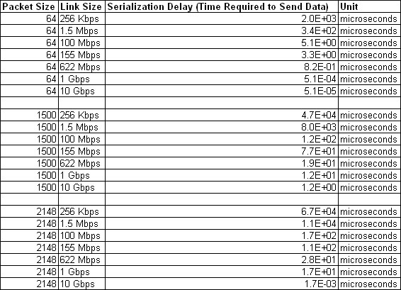
Figure 6-32 Effect of packet size (in bytes) versus the link size
In Figure 6-32, the amount of time in microseconds that is required to transmit a packet across network links of varying bandwidth capacity is compared. The following packet sizes are used:
•64 bytes: The size of the common ping packet
•1500 bytes: The size of the standard TCP/IP packet
•2148 bytes: The size of an FC frame
Finally, your path maximum transmission unit (MTU) affects the delay that is incurred to get a packet from one location to another location. An MTU might cause fragmentation, or be too large and cause too many retransmits when a packet is lost.
Hung I/O
An hung I/O condition is reached when a write operation is delayed in the IBM Spectrum Virtualize stack for a significant time (typically seconds). This condition is monitored by IBM Spectrum Virtualize, which eventually leads to a 1920 error if the delay is higher than maxreplicationdelay settings.
Hung I/Os can be caused by many factors, such as back-end performance, cache fullness, internal resource starvation, and remote copy issues. When the maxreplicationdelay setting triggers a 1920 error, the following areas must be investigated:
•Inter-site network disconnections. This kind of event generates partnership instability, which leads the mirrored write operations to be delayed until the condition is resolved.
•Secondary system poor performance. In the case of bad performance, the secondary system can become virtually unresponsive, which delays the replica of the write operations.
•Primary or secondary system node warmstarts. During a node warmstart, the system freezes all the I/Os for few seconds to get a consistent state of the cluster resources. These events often are not directly related to the remote copy operations.
|
Note: The maxreplicationdelay trigger can occur, even if the cause of the write delay is not related to the remote copy. In this case, the replication suspension does not resolve the hung I/O condition.
To exclude the remote copy as cause of the hung I/O, the duration of the delay (peek write response time) can be checked by using tools, such as Spectrum Control. If the measured delay is greater than the maxreplicationdelay settings, it is unlikely that the remote copy is responsible.
|
Recovery after 1920 errors
After a 1920 error occurs, the Global Mirror auxiliary volumes are no longer in a Consistent Synchronized state. You must establish the cause of the problem and fix it before you restart the relationship.
When the relationship is restarted, you must resynchronize it. During this period, the data on the Metro Mirror or Global Mirror auxiliary volumes on the secondary system is inconsistent, and your applications cannot use the volumes as backup disks. To address this data consistency exposure on the secondary system, a FlashCopy of the auxiliary volumes can be created to maintain a consistent image until the Global Mirror (or the Metro Mirror) relationships are synchronized again and back in a consistent state.
IBM Spectrum Virtualize provides the Remote Copy Consistency Protection feature that automates this process. When Consistency Protection is configured, the relationship between the primary and secondary volumes does not go in to the Inconsistent copying status after it is restarted. Instead, the system uses a secondary change volume to automatically copy the previous consistent state of the secondary volume.
The relationship automatically moves to the Consistent copying status as the system resynchronizes and protects the consistency of the data. The relationship status changes to Consistent synchronized when the resynchronization process completes.
For more information about the Consistency Protection feature, see Implementing the IBM SAN Volume Controller with IBM Spectrum Virtualize Version 8.4.2, SG24-8507.
To ensure that the system can handle the background copy load, delay restarting the Metro Mirror or Global Mirror relationship until a quiet period occurs. If the required link capacity is unavailable, you might experience another 1920 error, and the Metro Mirror or Global Mirror relationship might stop in an inconsistent state.
Copy services tools, like IBM Copy Services Manager (CSM), or manual scripts can be used to automatize the relationships to restart after a 1920 error. CSM implements a logic to avoid recurring restart operations in case of a persistent problem. CSM attempts an automatic restart for every occurrence of 1720/1920 error a certain number of times (determined by the gmlinktolerance value) within a 30 minute time period.
If the number of allowable automatic restarts is exceeded within the time period, CSM will not automatically restart GM on the next 1720/1920 error. Furthermore, with CSM it is possible to specify the amount of time, in seconds, in which the tool will wait after an 1720/1920 error before automatically restarting the GM. For more information, see this IBM Documentation web page.
|
Tip: When implementing automatic restart functions, it is advised to preserve the data consistency on GM target volumes during the resychronization by using features, such as FlashCopy or Consistency Protection.
|
Adjusting the Global Mirror settings
Although the default values are valid in most configurations, the settings of the gmlinktolerance and gmmaxhostdelay can be adjusted to accommodate particular environment or workload conditions.
For example, Global Mirror is designed to look at average delays. However, some hosts such as VMware ESX might not tolerate a single I/O getting old, for example, 45 seconds, before it decides to reboot. Given that it is better to terminate a Global Mirror relationship than it is to reboot a host, you might want to set gmlinktolerance to something like 30 seconds and then compensate so that you do not get too many relationship terminations by setting gmmaxhostdelay to something larger, such as 100 ms.
If you compare the two approaches, the default (gmlinktolerance 300, gmmaxhostdelay 5) is a rule that “If more than one third of the I/Os are slow and that happens repeatedly for 5 minutes, then terminate the busiest relationship in that stream.” In contrast, the example of gmlinktolerance 30, gmmaxhostdelay 100 is a rule that “If more than one third of the I/Os are extremely slow and that happens repeatedly for 30 seconds, then terminate the busiest relationship in the stream.”
So one approach is designed to pick up general slowness, and the other approach is designed to pick up shorter bursts of extreme slowness that might disrupt your server environment. The general recommendation is to change the gmlinktolerance and gmmaxhostdelay values progressively and evaluate the overall impact to find an acceptable compromise between performances and Global Mirror stability.
You can even disable the gmlinktolerance feature by setting the gmlinktolerance value to 0. However, the gmlinktolerance parameter cannot protect applications from extended response times if it is disabled. You might consider disabling the gmlinktolerance feature in the following circumstances:
•During SAN maintenance windows, where degraded performance is expected from SAN components and application hosts can withstand extended response times from Global Mirror volumes.
•During periods when application hosts can tolerate extended response times and it is expected that the gmlinktolerance feature might stop the Global Mirror relationships. For example, you are testing usage of an I/O generator that is configured to stress the back-end storage. Then, the gmlinktolerance feature might detect high latency and stop the Global Mirror relationships. Disabling the gmlinktolerance parameter stops the Global Mirror relationships at the risk of exposing the test host to extended response times.
Another tunable parameter that interacts with the GM is the maxreplicationdelay. Note that the maxreplicationdelay settings do not mitigate the 1920 error occurrence because it actually adds a trigger to the 1920 error itself. However, the maxreplicationdelay provides users with a fine granularity mechanism to manage the hung I/Os condition and it can be used in combination with gmlinktolerance and gmmaxhostdelay settings to better address particular environment conditions.
In the above VMware example, an alternative option is to set the maxreplicationdelay to 30 seconds and leave the gmlinktolerance and gmmaxhostdelay settings to their default. With these settings, the maxreplicationdelay timeout effectively handles the hung I/Os conditions, while the gmlinktolerance and gmmaxhostdelay settings still provide an adequate mechanism to protect from ongoing performance issues.
6.4 Native IP replication
The native IP replication feature enables replication between any IBM Spectrum Virtualize products by using the built-in networking ports or optional 1/10 Gb adapter.
Native IP replication uses SANslide technology developed by Bridgeworks Limited of Christchurch, UK. They specialize in products that can bridge storage protocols and accelerate data transfer over long distances. Adding this technology at each end of a wide area network (WAN) TCP/IP link significantly improves the utilization of the link.
This technology improves the link utilization by applying patented artificial intelligence (AI) to hide latency that is normally associated with WANs. Doing so can greatly improve the performance of mirroring services, in particular GMCV over long distances.
6.4.1 Native IP replication technology
Remote Mirroring over IP communication is supported on the IBM FlashSystem systems by using Ethernet communication links. The IBM Spectrum Virtualize Software IP replication uses innovative Bridgeworks SANSlide technology to optimize network bandwidth and utilization. This new function enables the use of a lower-speed and lower-cost networking infrastructure for data replication.
Bridgeworks’ SANSlide technology, which is integrated into the IBM Spectrum Virtualize Software, uses artificial intelligence to help optimize network bandwidth use and adapt to changing workload and network conditions. This technology can improve remote mirroring network bandwidth usage up to three times. It can enable clients to deploy a less costly network infrastructure, or speed up remote replication cycles to enhance disaster recovery effectiveness.
With an Ethernet network data flow, the data transfer can slow down over time. This condition occurs because of the latency that is caused by waiting for the acknowledgment of each set of packets that are sent. The next packet set cannot be sent until the previous packet is acknowledged, as shown in Figure 6-33 on page 330.
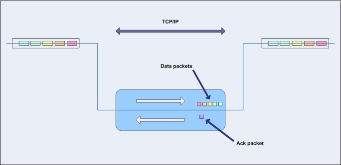
Figure 6-33 Typical Ethernet network data flow
However, by using the embedded IP replication, this behavior can be eliminated with the enhanced parallelism of the data flow. This parallelism uses multiple virtual connections (VCs) that share IP links and addresses.
The artificial intelligence engine can dynamically adjust the number of VCs, receive window size, and packet size as appropriate to maintain optimum performance. While the engine is waiting for one VC’s ACK, it sends more packets across other VCs. If packets are lost from any VC, data is automatically retransmitted, as shown in Figure 6-34.

Figure 6-34 Optimized network data flow by using Bridgeworks SANSlide technology
For more information about this technology, see IBM SAN Volume Controller and Storwize Family Native IP Replication, REDP-5103.
Metro Mirror, Global Mirror, and Global Mirror Change Volume are supported with native
IP partnership.
IP partnership.
6.4.2 IP partnership limitations
The following prerequisites and assumptions must be considered before IP partnership between two IBM Spectrum Virtualize based systems can be established:
•The systems have 7.2 or later code levels.
•The systems have the necessary licenses that enable Remote Copy partnerships to be configured between two systems. A separate license is not required to enable IP partnership.
•The storage SANs are configured correctly and the correct infrastructure to support the systems in Remote Copy partnerships over IP links is in place.
•The two systems must be able to ping each other and perform the discovery.
•The maximum number of partnerships between the local and remote systems, including IP and FC partnerships, is limited to the current maximum that is supported, which is three partnerships (four systems total).
|
Note: With code versions earlier than 8.4.2, only a single partnership over IP is supported.
|
•A system can have simultaneous partnerships over FC and IP, but with separate systems. The FC zones between two systems must be removed before an IP partnership is configured.
•The use of WAN-optimization devices, such as Riverbed, is not supported in IP partnership configurations containing SAN Volume Controller.
•IP partnerships are supported with 25, 10, and 1 Gbps links. However, the intermix /on a single link is not supported.
•The maximum supported round-trip time is 80 ms for 1 Gbps links.
•The maximum supported round-trip time is 10 ms for 25 and 10 Gbps links.
•The minimum supported link bandwidth is 10 Mbps.
•The inter-cluster heartbeat traffic uses 1 Mbps per link.
•Migrations of Remote Copy relationships directly from FC-based partnerships to IP partnerships are not supported.
•IP partnerships between the two systems can be over either IPv4 or IPv6, but not both.
•Virtual LAN (VLAN) tagging of the IP addresses that are configured for Remote Copy is supported.
•Management IP and Internet SCSI (iSCSI) IP on the same port can be in a different network.
•An added layer of security is provided by using Challenge Handshake Authentication Protocol (CHAP) authentication.
•Direct attached systems configurations are supported with the following restrictions:
– Only two direct attach link are allowed.
– The direct attach links must be on the same I/O group.
– Use two portsets, where a portset contains only the two ports that are directly linked.
•Transmission Control Protocol (TCP) ports 3260 and 3265 are used for IP partnership communications. Therefore, these ports must be open in firewalls between the systems.
•Network address translation (NAT) between systems that are being configured in an IP Partnership group is not supported.
•Only one Remote Copy data session per portset can be established. It is intended that only one connection (for sending or receiving Remote Copy data) is made for each independent physical link between the systems.
|
Note: A physical link is the physical IP link between the two sites, A (local) and B (remote). Multiple IP addresses on local system A can be connected (by Ethernet switches) to this physical link. Similarly, multiple IP addresses on remote system B can be connected (by Ethernet switches) to the same physical link. At any point, only a single IP address on cluster A can form an RC data session with an IP address on cluster B.
|
•The maximum throughput is restricted based on the use of 1 Gbps or 10 Gbps Ethernet ports. The output varies based on distance (for example, round-trip latency) and quality of communication link (for example, packet loss). The following maximum throughputs are achievable:
– One 1 Gbps port can transfer up to 120 MB
– One 10 Gbps port can transfer up to 600 MB
Table 6-9 lists the IP replication limits.
Table 6-9 IP replication limits
|
Remote Copy property
|
Maximum
|
Apply to
|
Comment
|
|
Inter-system IP partnerships per system
|
3 MBps
|
All models
|
A system can be partnered with up to three remote systems.
|
|
Inter-site links per IP partnership
|
2 MBps
|
All models
|
A maximum of two inter-site links can be used between two IP partnership sites.
|
|
Ports per node
|
1 MBps
|
All models
|
A maximum of one port per node can be used for IP partnership
|
|
IP partnership Software Compression Limit
|
140 MBps
|
All models
|
|
6.4.3 VLAN support
VLAN tagging is supported for iSCSI host attachment and IP replication. Hosts and remote-copy operations can connect to the system through Ethernet ports. Each traffic type has different bandwidth requirements, which can interfere with each other if they share a port.
VLAN tagging creates two separate connections on the same IP network for different types of traffic. The system supports VLAN configuration on both IPv4 and IPv6 connections.
When the VLAN ID is configured for the IP addresses that are used for iSCSI host attach or IP replication, the suitable VLAN settings on the Ethernet network and servers must be configured correctly to avoid connectivity issues. After the VLANs are configured, changes to the VLAN settings disrupt iSCSI and IP replication traffic to and from the partnerships.
During the VLAN configuration for each IP address, the VLAN settings for the local and failover ports on two nodes of an I/O Group can differ. To avoid any service disruption, switches must be configured so that the failover VLANs are configured on the local switch ports and the failover of IP addresses from a failing node to a surviving node succeeds.
If failover VLANs are not configured on the local switch ports, no paths are available to the Spectrum Virtualize system during a node failure and the replication fails.
Consider the following requirements and procedures when implementing VLAN tagging:
•VLAN tagging is supported for IP partnership traffic between two systems.
•VLAN provides network traffic separation at the layer 2 level for Ethernet transport.
•VLAN tagging by default is disabled for any IP address of a node port. You can use the CLI or GUI to set the VLAN ID for port IPs on both systems in the IP partnership.
•When a VLAN ID is configured for the port IP addresses that are used in Remote Copy port groups, appropriate VLAN settings on the Ethernet network must also be properly configured to prevent connectivity issues.
Setting VLAN tags for a port is disruptive. Therefore, VLAN tagging requires that you stop the partnership first before you configure VLAN tags. Then, restart again when the configuration is complete.
6.4.4 IP compression
IBM FlashSystem can leverage the IP compression capability to speed up replication cycles or to reduce bandwidth utilization.
This feature reduces the volume of data that must be transmitted during Remote Copy operations by using compression capabilities similar to those experienced with existing Real-time Compression implementations.
|
No License: The IP compression feature does not require an RtC software license.
|
The data compression is made within the IP replication component of the IBM Spectrum Virtualize code. It can be used with all the Remote Copy technology (Metro Mirror, Global Mirror, and GMCV). The IP compression feature provides two kinds of compression mechanisms: the hardware compression and software compression.
The IP compression can be enabled on hardware configurations that support hardware-assisted compression acceleration engines. The hardware compression is active when compression accelerator engines are available, otherwise software compression is used.
Hardware compression makes use of currently underused compression resources. The internal resources are shared between data and IP compression. Software compression uses the system CPU and might have an impact on heavily used systems.
To evaluate the benefits of the IP compression, the Comprestimator tool can be used to estimate the compression ratio of the data to be replicated. The IP compression can be enabled and disabled without stopping the Remote Copy relationship by using the mkippartnership and chpartnership commands with the -compress parameter. Furthermore, in systems with replication enabled in both directions, the IP compression can be enabled in only one direction. IP compression is supported for IPv4 and IPv6 partnerships.
6.4.5 Replication portsets
This section describes the replication portsets and different ways to configure the links between the two remote systems. Two systems can be connected over one link or, at most, two links. To address the requirement to enable the systems to know about the physical links between the two sites, the concept of a portset is used.
Portsets are groupings of logical addresses that are associated with the specific traffic types. IBM Spectrum Virtualize supports portsets for host attachment (iSCSI or iSER), back-end storage connectivity (iSCSI only), and IP replication. Each physical Ethernet Port can have maximum 64 IP addresses with each IP on unique portset.
A portset object is a system-wide object that might contain IP addresses from every I/O group. Figure 6-35 shows a sample of portsets definition across the canister ports in a two IO group clustered FlashSystem.

Figure 6-35 Portsets
Complete the following steps to establish an IP partnership between two systems:
1. Identify the Ethernet ports to be used for the IP replication.
2. Define a replication type portset.
3. Set the IP addresses to the identified ports and add them to the portset.
4. Create the IP partnership from both systems specifying the portset to be used.
Multiple FlashSystem canisters can be connected to the same physical long-distance link by setting IP addresses in the same portset. Samples of supported configurations are described in 6.4.6, “Supported configurations examples” on page 336.
In scenarios with two physical links between the local and remote clusters, two separate replication portset must be used to designate which IP addresses are connected to which physical link. The relationship between the physical links and the replication portsets is not monitored by the IBM Spectrum Virtualize code. Therefore, two different replication portsets can be used with a single physical link and vice versa.
All IP addresses in a replication portset must be IPv4 or IPv6 addresses (IP types cannot be mixed). IP addresses can be shared among replication and host type portsets, although it is not recommended.
|
Note: The concept of a portset was introduced in IBM Spectrum Virtualize version 8.4.2 and the IP Multi-tenancy feature. Versions before 8.4.2 use the Remote Copy Port Groups concept to tag the IP addresses to associate with an IP partnership. For more information about the Remote Copy Port Group configuration, see this IBM Documentation web page.
When upgrading to version 8.4.2, an automatic process occurs to convert the Remote Copy Port Groups configuration to an equivalent replication portset configuration.
|
Failover operations within and between portsets
Within one portset, only one IP from each system is selected for sending and receiving Remote Copy data at any one time. Therefore, on each system, at most one IP for each portset group is reported as used.
If the IP partnership cannot continue over an IP, the system fails over to another IP within that portset. Some reasons this issue might occur include the switch to which it is connected fails, the node goes offline, or the cable that is connected to the port is unplugged.
For the IP partnership to continue during a failover, multiple ports must be configured within the portset. If only one link is configured between the two systems, configure at least two IPs (one per node) within the portset. You can configure these two IPs on two nodes within the same I/O group or within separate I/O groups.
While failover is in progress, no connections in that portset exist between the two systems in the IP partnership for a short time. Typically, failover completes within 30 seconds to 1 minute. If the systems are configured with two portsets, the failover process within each portset continues independently of each other.
The disadvantage of configuring only one link between two systems is that, during a failover, a discovery is initiated. When the discovery succeeds, the IP partnership is reestablished. As a result, the relationships might stop, in which case a manual restart is required. To configure two inter-system links, you must configure two replication type portsets.
When a node fails in this scenario, the IP partnership can continue over the other link until the node failure is rectified. Failback then occurs when both links are again active and available to the IP partnership. The discovery is triggered so that the active IP partnership data path is made available from the new IP address.
In a two-node system, or more than one I/O Group exists and the node in the other I/O group has IP addresses within the replication portset, the discovery is triggered. The discovery makes the active IP partnership data path available from the new IP address.
6.4.6 Supported configurations examples
Different IP replication topologies are available depending on the number of physical links, the number of nodes and the number of IP partnerships. In the following sections, some typical configurations are described.
Single partnership configurations
In this section, some single partnership configurations are described.
Single inter-site link configurations
Consider single control enclosure systems in IP partnership over a single inter-site link (with failover ports configured), as shown in Figure 6-36.

Figure 6-36 Only one link on each system and canister with failover ports configured
Figure 6-36 shows two systems: System A and System B. A single portset is used with IP addressees on two Ethernet ports, one each on Canister A1 and Canister A2 on System A. Similarly, a single portset is configured on two Ethernet ports on Canister B1 and Canister B2 on System B.
Although two ports on each system are configured in the portset, only one Ethernet port in each system actively participates in the IP partnership process. This selection is determined by a path configuration algorithm that is designed to choose data paths between the two systems to optimize performance.
The other port on the partner canister in the control enclosure behaves as a standby port that is used during a canister failure. If Canister A1 fails in System A, IP partnership continues servicing replication I/O from Ethernet Port 2 because a failover port is configured on Canister A2 on Ethernet Port 2.
However, it might take some time for discovery and path configuration logic to reestablish paths post failover. This delay can cause partnerships to change to Not_Present for that time. The details of the particular IP port that is actively participating in IP partnership is provided in the lspartnership output (reported as link1_ip_id and link2_ip_id).
This configuration has the following characteristics:
•Each canister in the control enclosure has ports with IP addresses defined in the same replication type portset. However, only one path is active at any time at each system.
•If Canister A1 in System A or Canister B2 in System B fails in the respective systems, IP partnerships rediscovery is triggered and continues servicing the I/O from the failover port.
•The discovery mechanism that is triggered because of failover might introduce a delay where the partnerships momentarily change to the Not_Present state and recover.
A four control enclosures system in IP partnership with two control enclosure system over single inter-site link is shown in Figure 6-37.
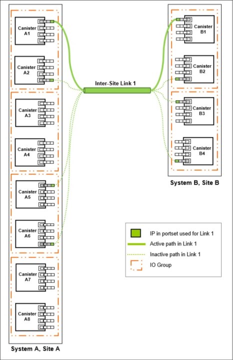
Figure 6-37 Configuration 2: clustered systems single inter-site link with only one link
Figure 6-37 on page 338 shows a four control enclosure system (System A in Site A) and a two control enclosure system (System B in Site B). A single replication portset is used on canisters A1, A2, A5, and A6 on System A at Site A. Similarly, a single portset is used on canisters B1, B2, B3, and B4 on System B.
Although four control enclosures are in System A, only two control enclosure are configured for IP partnerships. Port selection is determined by a path configuration algorithm. The other ports play the role of standby ports.
If Canister A1 fails in System A, IP partnership continues using one of the ports that is configured in the portset from any of the canisters from either of the two control enclosures in System A.
However, it might take some time for discovery and path configuration logic to reestablish paths post-failover. This delay might cause partnerships to change to the Not_Present state. This process can lead to Remote Copy relationships stopping. The administrator must manually start them if the relationships do not auto-recover.
The details of which particular IP port is actively participating in IP partnership process is provided in lspartnership output (reported as link1_ip_id and link2_ip_id).
This configuration includes the following characteristics:
•The replication portset that is used contains IPs from canisters of all the control enclosures. However, only one path is active at any time at each system.
•If the Canister A1 in System A or the Canister B2 in System B fails in the system, the IP partnerships trigger discovery and continue servicing the I/O from the failover ports.
•The discovery mechanism that is triggered because of failover might introduce a delay where the partnerships momentarily change to the Not_Present state and then recover.
•The bandwidth of the single link is used completely.
Two inter-site link configurations
A single control enclosure system with two inter-site links configuration is shown in Figure 6-38.
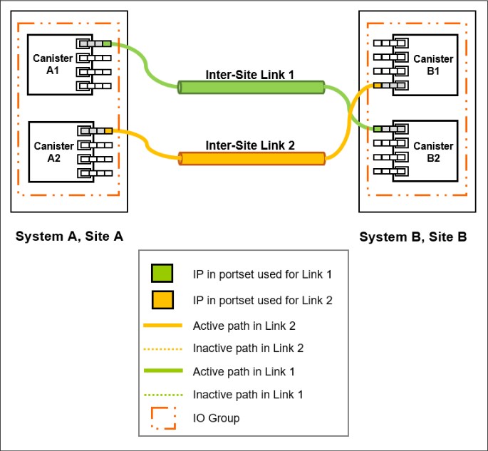
Figure 6-38 Dual links with two replication portset on each system configured
As shown in Figure 6-38, two replication portsets are configured on System A and System B because two inter-site links are available. In this configuration, the failover ports are not configured on partner canisters in the control enclosure. Rather, the ports are maintained in different portsets on both of the canisters. They can remain active and participate in IP partnership by using both of the links. Failover ports cannot be used with this configuration because only one active path per canister per partnership is allowed.
However, if either of the canisters in the control enclosure fail (that is, if Canister A1 on System A fails), the IP partnership continues from only the available IP that is configured in portset associated to link 2. Therefore, the effective bandwidth of the two links is reduced to 50% because only the bandwidth of a single link is available until the failure is resolved.
This configuration includes the following characteristics:
•Two inter-site links exist, and two replication portset are used.
•Each node has only one IP in each replication portset.
•Both IP in the two portsets participate simultaneously in IP partnerships. Therefore, both of the links are used.
•During canister failure or link failure, the IP partnership traffic continues from the other available link. Therefore, if two links of 10 Mbps each are available and you have 20 Mbps of effective link bandwidth, bandwidth is reduced to 10 Mbps only during a failure.
•After the canister failure or link failure is resolved and failback happens, the entire bandwidth of both of the links is available as before.
A four control enclosures clustered system in IP partnership with a two control enclosure clustered system over dual inter-site links is shown in Figure 6-39.

Figure 6-39 Clustered systems with dual inter-site links between the two systems
Figure 6-39 on page 341 shows a four control enclosure System A in Site A and a two control enclosure System B in Site B. Canisters from only two control enclosures are configured with replication portsets in System A.
In this configuration, two links and two control enclosures are configured with replication portsets. However, path selection logic is managed by an internal algorithm. Therefore, this configuration depends on the pathing algorithm to decide which of the canisters actively participate in IP partnership. Even if Canister A5 and Canister A6 have IPs configured within replication portsets properly, active IP partnership traffic on both of the links can be driven from Canister A1 and Canister A2 only.
If Canister A1 fails in System A, IP partnership traffic continues from Canister A2 (that is, link 2). The failover also causes IP partnership traffic to continue from Canister A5 on which a portset associated to link 1 is configured. The details of the specific IP port actively participating in IP partnership process is provided in the lspartnership output (reported as link1_ip_id and link2_ip_id).
This configuration includes the following characteristics:
•Two control enclosure have IPs configured in two replication portsets because two inter-site links for participating in IP partnership are used. However, only one IP per system in a particular portset remains active and participates in IP partnership.
•One IP per system from each replication portset participates in IP partnership simultaneously. Therefore, both of the links are used.
•If a canister or port on the canister that is actively participating in IP partnership fails, the Remote Copy data path is established from that port because another IP is available on an alternative canister in the system within the replication portset.
•The path selection algorithm starts discovery of available IPs in the affected portset in the alternative I/O groups and paths are reestablished. This process restores the total bandwidth across both links.
Multiple partnerships configurations
In this section some multiple partnerships configurations are described.
Figure 6-40 on page 343 shows a two control enclosures System A in Site A, a two control enclosures System B in Site B and a two control enclosures System C in Site C.
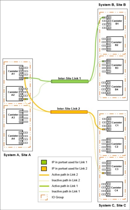
Figure 6-40 Multiple IP partnerships with two links and only one IO group
In this configuration, two links and only one control enclosure are configured with replication portsets in System A. Both replication portsets use the same Ethernet ports in canister A1 and A2. System B uses a replication portset associated to link 1, while System C uses a replication portset associated to link 2. System B and System C have configured portsets across both control enclosures.
However, path selection logic is managed by an internal algorithm. Therefore, this configuration depends on the pathing algorithm to decide which of the canisters actively participate in a IP partnerships. In this example, the active paths go from Canister A1 to Canister B1 and Canister A1 to Canister C1, respectively. In this configuration, multiple paths are allowed for a single canister because they are used for different IP partnerships.
If Canister A1 fails in System A, IP partnerships continues servicing replication I/O from Canister A2 because a failover port is configured on that node.
However, it might take some time for discovery and path configuration logic to reestablish paths post failover. This delay can cause partnerships to change to Not_Present for that time and this can lead to a replication stopping. The details of the specific IP port that is actively participating in IP partnership is provided in the lspartnership output (reported as link1_ip_id and link2_ip_id).
This configuration includes the following characteristics:
•One IP per system from each replication portset participates in IP partnership simultaneously. Therefore, both of the links are used.
•Replication portsets on System A for both links are defined in the same physical ports
•If a canister or port on the canister that is actively participating in IP partnership fails, the Remote Copy data path is established from that port because another IP is available on an alternative canister in the system within the replication portset.
•The path selection algorithm starts discovery of available IPs in the affected portset in the alternative control enclosures and paths are reestablished. This process restores the total bandwidth across both links.
Finally, an alternative partnership layout configuration is shown in Figure 6-41 on page 345.

Figure 6-41 Multiple IP partnerships with two links
In this configuration, two links and two control enclosures are configured with replication portsets in System A. On System A control enclosure 0 (Canister A1 and Canister A2) uses IPs on the replication portset associated to link 1, while control enclosure 1 (Canister A3 and Canister A4) uses IPs on the replication portset associated to link 2. System B uses a replication portset associated to link 1, while System C uses a replication portset associated to link 2. System B and System C have configured portsets across both control enclosures.
However, path selection logic is managed by an internal algorithm. Therefore, this configuration depends on the pathing algorithm to decide which of the nodes actively participate in IP partnerships. In this example, the active paths go from Canister A1 to Canister B1 and Canister A4 to Canister C1 for System A to System B and System A to System C, respectively.
If Canister A1 fails in System A, IP partnership for System A to System B continues servicing replication I/O from Canister A2 because a failover port is configured on that node.
However, it might take some time for discovery and path configuration logic to reestablish paths post failover. This delay can cause partnerships to change to Not_Present for that time, which can lead to a replication stopping. The partnership for System A to System C remains unaffected. The details of the specific IP port that is actively participating in IP partnership is provided in the lspartnership output (reported as link1_ip_id and link2_ip_id).
This configuration includes the following characteristics:
•One IP per system from each replication portset participates in IP partnership simultaneously. Therefore, both of the links are used.
•Replication portsets on System A for the two links are defined in different physical ports
•If a canister or port on the canister that is actively participating in IP partnership fails, the Remote Copy data path is established from that port because another IP is available on an alternative canister in the system within the replication portset.
•The path selection algorithm starts discovery of available IPs in the affected portset in the alternative canisters and paths are reestablished. This process restores the total bandwidth across both links.
•If a canister or link failure occurs, only one partnership is affected.
|
Replication portsets: As described in these sections, configuring two replication portsets provides more bandwidth and resilient configurations in case of a link failure. Two replication portsets also can be configured with a single physical link. This configuration make sense only if the total link bandwidth exceeds the aggregate bandwidth of two replication portsets together. The use of two portsets when the link bandwidth does not provide the aggregate throughput can lead to network resources contention and bad link performance.
|
6.4.7 Native IP replication performance consideration
A number of factors affect the performance of an IP partnership. Some of these factors are latency, link speed, number of intersite links, host I/O, MDisk latency, and hardware. Since the introduction, many improvements have been made to make the IP replication better performing and more reliable.
Nevertheless, in presence of poor quality networks that have significant packet loss and high latency, the actual usable bandwidth might decrease considerably.
Figure 6-42 shows the throughput trend for a 1 Gbps port in respect of the packet loss ratio and the latency.

Figure 6-42 1 Gbps port throughput trend
The chart in Figure 6-42 shows how the combined effect of the packet loss and the latency can lead to a throughput reduction of more than 85%. For these reasons, the IP replication option should be considered only for the replication configuration that is not affected by poor quality and poor performing networks. Due to its characteristic of low-bandwidth requirement, the GMCV is the preferred solution with the IP replication.
To improve the performance when using compression and IP partnership in the same system, it is advised that you use a different port for iSCSI host I/O and IP partnership traffic. Also, use a different VLAN ID for iSCSI host I/O and IP partnership traffic.
6.5 Volume mirroring
By using volume mirroring, you can have two physical copies of a volume that provide a basic RAID-1 function. These copies can be in the same storage pool or in different storage pools, with different extent sizes of the storage pool. Typically. the two copies are allocated in different storage pools.
The first storage pool contains the original (primary volume copy). If one storage controller or storage pool fails, a volume copy is not affected if it has been placed on a different storage controller or in a different storage pool.
If a volume is created with two copies, both copies use the same virtualization policy. However, you can have two copies of a volume with different virtualization policies. In combination with thin-provisioning, each mirror of a volume can be thin-provisioned, compressed or fully allocated, and in striped, sequential, or image mode.
A mirrored (secondary) volume has all of the capabilities of the primary volume copy. It also has the same restrictions (for example, a mirrored volume is owned by an I/O Group, just as any other volume). This feature also provides a point-in-time copy function that is achieved by “splitting” a copy from the volume. However, the mirrored volume does not address other forms of mirroring based on Remote Copy (Global or Metro Mirror functions), which mirrors volumes across I/O Groups or clustered systems.
One copy is the primary copy, and the other copy is the secondary copy. Initially, the first volume copy is the primary copy. You can change the primary copy to the secondary copy
if required.
if required.
Figure 6-43 shows an overview of volume mirroring.
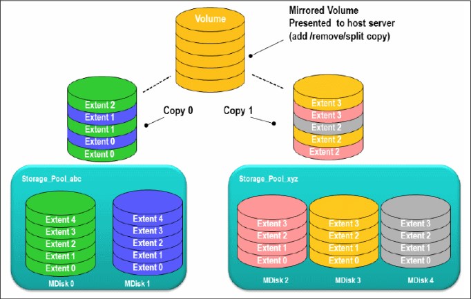
Figure 6-43 Volume mirroring overview
6.5.1 Read and write operations
Read and write operations behavior depends on the status of the copies and on other environment settings. During the initial synchronization or a resynchronization, only one of the copies is in synchronized status, and all the reads are directed to this copy. The write operations are directed to both copies.
When both copies are synchronized, the write operations are again directed to both copies. The read operations usually are directed to the primary copy, unless the system is configured in Enhanced Stretched Cluster topology, which applies to SAN Volume Controller system types only.
During back-end storage failure, note the following points:
•If one of the mirrored volume copies is temporarily unavailable, the volume remains accessible to servers.
•The system remembers which areas of the volume are written and resynchronizes these areas when both copies are available.
•The remaining copy can service read I/O when the failing one is offline, without user intervention.
6.5.2 Volume mirroring use cases
Volume mirroring offers the capability to provide extra copies of the data that can be used for High Availability solutions and data migration scenarios. You can convert a non-mirrored volume into a mirrored volume by adding a copy. When a copy is added using this method, the cluster system synchronizes the new copy so that it is the same as the existing volume. You can convert a mirrored volume into a non-mirrored volume by deleting one copy or by splitting one copy to create a new non-mirrored volume.
|
Access: Servers can access the volume during the synchronization processes described.
|
You can use mirrored volumes to provide extra protection for your environment or to perform a migration. This solution offers several options:
•Export to Image mode
This option allows you to move storage from managed mode to image mode. This option is useful if you are using IBM FlashSystem as a migration device. For example, suppose vendor A’s product cannot communicate with vendor B’s product, but you need to migrate existing data from vendor A to vendor B.
Using Export to image mode allows you to migrate data by using the Copy Services functions and then return control to the native array, while maintaining access to the hosts.
•Import to Image mode
This option allows you to import an existing storage MDisk or logical unit number (LUN) with its existing data from an external storage system, without putting metadata on it.
The existing data remains intact. After you import it, the volume mirroring function can be used to migrate the storage to the other locations, while the data remains accessible to your hosts.
The existing data remains intact. After you import it, the volume mirroring function can be used to migrate the storage to the other locations, while the data remains accessible to your hosts.
•Volume cloning by using volume mirroring and then by using the Split into New Volume option
This option allows any volume to be cloned without any interruption to the host access. You have to create two mirrored copies of data and then break the mirroring with the split option to make two independent copies of data. This option doesn’t apply to already mirrored volumes.
•Volume pool migration using the volume mirroring option
This option allows any volume to be moved between storage pools without any interruption to the host access. You might use this option to move volumes as an alternative to Migrate to Another Pool function.
Compared to the Migrate to Another Pool function, volume mirroring provides more manageability because it can be suspended and resumed anytime and also it allows you to move volumes among pools with different extent sizes. This option doesn’t apply to already mirrored volumes.
|
Use case: Volume mirroring can be used to migrate volumes from and to DRPs which do not support extent based migrations. For more information, see 4.3.6, “Data migration with DRP” on page 145.
|
•Volume capacity saving change
This option allows you to modify the capacity saving characteristics of any volume from standard to thin provisioned or compressed and vice versa, without any interruption to host access. This option works the same as the volume pool migration but specifying a different capacity saving for the newly created copy. This option doesn’t apply to already mirrored volumes.
When you use volume mirroring, consider how quorum candidate disks are allocated. Volume mirroring maintains some state data on the quorum disks. If a quorum disk is not accessible and volume mirroring cannot update the state information, a mirrored volume might need to be taken offline to maintain data integrity. To ensure the high availability of the system, ensure that multiple quorum candidate disks, which are allocated on different storage systems, are configured.
|
Quorum disk consideration: Mirrored volumes can be taken offline if there is no quorum disk available. This behavior occurs because synchronization status for mirrored volumes is recorded on the quorum disk. To protect against mirrored volumes being taken offline, follow the guidelines for setting up quorum disks.
|
The following are other volume mirroring usage cases and characteristics:
•Creating a mirrored volume:
– The maximum number of copies is two.
– Both copies are created with the same virtualization policy, by default.
To have a volume mirrored using different policies, you need to add a volume copy with a different policy to a volume that has only one copy.
– Both copies can be located in different storage pools. The first storage pool that is specified contains the primary copy.
– It is not possible to create a volume with two copies when specifying a set of MDisks.
•Add a volume copy to an existing volume:
– The volume copy to be added can have a different space allocation policy.
– Two existing volumes with one copy each cannot be merged into a single mirrored volume with two copies.
•Remove a volume copy from a mirrored volume:
– The volume remains with only one copy.
– It is not possible to remove the last copy from a volume.
•Split a volume copy from a mirrored volume and create a new volume with the split copy:
– This function is only allowed when the volume copies are synchronized. Otherwise, use the -force command.
– It is not possible to recombine the two volumes after they have been split.
– Adding and splitting in one workflow enables migrations that are not currently allowed.
– The split volume copy can be used as a means for creating a point-in-time copy (clone).
•Repair or validate volume copies, by comparing them and performing the following three functions:
– Report the first difference found. It can iterate by starting at a specific LBA by using the -startlba parameter.
– Create virtual medium errors where there are differences. This is useful in case of back-end data corruption.
– Correct the differences that are found (reads from primary copy and writes to secondary copy).
•View to list volumes affected by a back-end disk subsystem being offline:
– Assumes that a standard use is for mirror between disk subsystems.
– Verifies that mirrored volumes remain accessible if a disk system is being shut down.
– Reports an error in case a quorum disk is on the back-end disk subsystem.
•Expand or shrink a volume:
– This function works on both of the volume copies at once.
– All volume copies always have the same size.
– All copies must be synchronized before expanding or shrinking them.
|
DRP limitation: DRPs do not support thin/compressed volumes shrinking.
|
•Delete a volume. When a volume gets deleted, all copies get deleted.
•Migration commands apply to a specific volume copy.
•Out-of-sync bitmaps share the bitmap space with FlashCopy and Metro Mirror/Global Mirror. Creating, expanding, and changing I/O groups might fail if there is insufficient memory.
•GUI views contain volume copy identifiers.
6.5.3 Mirrored volume components
Note the following points regarding mirrored volume components:
•A mirrored volume is always composed of two copies (copy 0 and copy1).
•A volume that is not mirrored consists of a single copy (which for reference might be copy 0 or copy 1).
A mirrored volume looks the same to upper-layer clients as a non-mirrored volume. That is, upper layers within the cluster software, such as FlashCopy and Metro Mirror/Global Mirror, and storage clients, do not know whether a volume is mirrored. They all continue to handle the volume as they did before without being aware of whether the volume is mirrored.
6.5.4 Volume mirroring synchronization options
As soon as a volume is created with two copies, copies are in the out-of-sync state. The primary volume copy (located in the first specified storage pool) is defined as in sync and the secondary volume copy as out of sync. The secondary copy is synchronized through the synchronization process.
This process runs at the default synchronization rate of 50 (as shown in Table 6-10 on page 353), or at the defined rate while creating or modifying the volume. For more information on the effect of the copy rate setting, see 6.5.5, “Volume mirroring performance considerations” on page 352. When the synchronization process is completed, the volume mirroring copies are in-sync state.
By default, when a mirrored volume is created a format process is also initiated. This process guarantees that the volume data is zeroed, avoiding access to data that is still present on reused extents.
This format process runs in background at the defined synchronization rate, as shown in Table 6-10 on page 353. Before Spectrum Virtualize version 8.4, the format processing overwrite with zeros only the Copy 0 and then synchronize the Copy 1. With version 8.4 or later, the format process is initiated concurrently to both volume mirroring copies and thus avoiding the second synchronization step.
You can specify that a volume is synchronized (-createsync parameter), even if it is not. Using this parameter can cause data corruption if the primary copy fails and leaves an unsynchronized secondary copy to provide data. Using this parameter can cause loss of read stability in unwritten areas if the primary copy fails, data is read from the primary copy, and then different data is read from the secondary copy. To avoid data loss or read stability loss, use this parameter only for a primary copy that has been formatted and not written to. When using the -createsync setting, the initial formatting is skipped.
Another example use case for -createsync is for a newly created mirrored volume where both copies are thin provisioned or compressed because no data has been written to disk and unwritten areas return zeros (0). If the synchronization between the volume copies has been lost, the resynchronization process is incremental. This term means that only grains that have been written to need to be copied, and then get synchronized volume copies again.
The progress of the volume mirror synchronization can be obtained from the GUI or by using the lsvdisksyncprogress command.
6.5.5 Volume mirroring performance considerations
Because the writes of mirrored volumes always occur to both copies, mirrored volumes put more workload on the cluster, the back-end disk subsystems, and the connectivity infrastructure. The mirroring is symmetrical, and writes are only acknowledged when the write to the last copy completes. The result is that if the volumes copies are on storage pools with different performance characteristics, the slowest storage pool determines the performance of writes to the volume. This performance applies when writes must be destaged to disk.
|
Tip: Locate volume copies of one volume on storage pools of the same or similar characteristics. Usually, if only good read performance is required, you can place the primary copy of a volume in a storage pool with better performance. Because the data is always only read from one volume copy, reads are not faster than without volume mirroring.
However, be aware that this is only true when both copies are synchronized. If the primary is out of sync, then reads are submitted to the other copy.
|
Synchronization between volume copies has a similar impact on the cluster and the back-end disk subsystems as FlashCopy or data migration. The synchronization rate is a property of a volume that is expressed as a value of 0 - 150. A value of 0 disables synchronization.
Table 6-10 shows the relationship between the rate value and the data copied per second.
Table 6-10 Relationship between the rate value and the data copied per second
|
User-specified rate attribute value per volume
|
Data copied per second
|
|
00
|
Synchronization is disabled
|
|
01 - 10
|
128 KB
|
|
11 - 20
|
256 KB
|
|
21 - 30
|
512 KB
|
|
31 - 40
|
1 MB
|
|
41 - 50
|
2 MB (50% is the default value)
|
|
51 - 60
|
4 MB
|
|
61 - 70
|
8 MB
|
|
71 - 80
|
6 MB
|
|
81 - 90
|
32 MB
|
|
91 - 100
|
64 MB
|
|
101 - 110
|
128 MB
|
|
111 - 120
|
256 MB
|
|
121 - 130
|
512 MB
|
|
131 - 140
|
1024 MB
|
|
141 - 150
|
2048 MB
|
|
Rate attribute value: The rate attribute is configured on each volume that you want to mirror. The default value of a new volume mirror is 50%.
|
In large, IBM FlashSystem configurations, the settings of the copy rate can considerably affect the performance in scenarios where a back-end storage failure occurs. For instance, consider a scenario where a failure of a back-end storage controller is affecting one copy of 300 mirrored volumes. The host continues the operations by using the remaining copy.
When the failed controller comes back online, the resynchronization process for all the 300 mirrored volumes starts at the same time. With a copy rate of 100 for each volume, this process would add a theoretical workload of 18.75 GBps, which will considerably overload
the system.
the system.
The general suggestion for the copy rate settings is then to evaluate the impact of massive resynchronization and set the parameter accordingly. Consider setting the copy rate to high values for initial synchronization only, and with a limited number of volumes at a time. Alternatively, consider defining a volume provisioning process that allows the safe creation of already synchronized mirrored volumes, as described in 6.5.4, “Volume mirroring synchronization options” on page 351.
Volume mirroring I/O time-out configuration
A mirrored volume has pointers to the two copies of data, usually in different storage pools, and each write completes on both copies before the host receives I/O completion status. For a synchronized mirrored volume, if a write I/O to a copy has failed or a long timeout has expired, then system has completed all available controller level Error Recovery Procedures (ERPs). In this case, that copy is taken offline and goes out of sync. The volume remains online and continues to service I/O requests from the remaining copy.
The Fast Failover feature isolates hosts from temporarily poorly-performing back-end storage of one Copy at the expense of a short interruption to redundancy. The fast failover feature behavior is that during normal processing of host write I/O, the system submits writes to both copies with a timeout of 10 seconds (20 seconds for stretched volumes). If one write succeeds and the other write takes longer than 5 seconds, then the slow write is stopped. The FC abort sequence can take around 25 seconds.
When the stop is completed, one copy is marked as out of sync and the host write I/O completed. The overall fast failover ERP aims to complete the host I/O in approximately 30 seconds (or 40 seconds for stretched volumes).
The fast failover can be set for each mirrored volume by using the chvdisk command and the mirror_write_priority attribute settings:
•Latency (default value): A short timeout prioritizing low host latency. This option enables the fast failover feature.
•Redundancy: A long timeout prioritizing redundancy. This option indicates a copy that is slow to respond to a write I/O can use the full ERP time. The response to the I/O is delayed until it completes to keep the copy in sync if possible. This option disables the fast failover feature.
Volume mirroring ceases to use the slow copy for 4 - 6 minutes, and subsequent I/O data is not affected by a slow copy. Synchronization is suspended during this period. After the copy suspension completes, volume mirroring resumes, which allows I/O data and synchronization operations to the slow copy that often quickly completes the synchronization.
If another I/O times out during the synchronization, then the system stops using that copy again for 4 - 6 minutes. If one copy is always slow, then the system tries it every 4 - 6 minutes and the copy gets progressively more out of sync as more grains are written. If fast failovers are occurring regularly, there is probably an underlying performance problem with the copy’s back-end storage.
The preferred mirror_write_priority setting for the Enhanced Stretched Cluster configurations is latency.
6.5.6 Bitmap space for out-of-sync volume copies
The grain size for the synchronization of volume copies is 256 KB. One grain takes up one bit of bitmap space. 20 MB of bitmap space supports 40 TB of mirrored volumes. This relationship is the same as the relationship for copy services (Global and Metro Mirror) and standard FlashCopy with a grain size of 256 KB (see Table 6-11).
Table 6-11 Relationship of bitmap space to volume mirroring address space
|
Function
|
Grain size in KB
|
1 byte of bitmap space gives a total of
|
4 KB of bitmap space gives a total of
|
1 MB of bitmap space gives a total of
|
20 MB of bitmap space gives a total of
|
512 MB of bitmap space gives a total of
|
|
Volume mirroring
|
256
|
2 MB of volume capacity
|
8 GB of volume capacity
|
2 TB of volume capacity
|
40 TB of volume capacity
|
1024 TB of volume capacity
|
|
Shared bitmap space: This bitmap space on one I/O group is shared between Metro Mirror, Global Mirror, FlashCopy, and volume mirroring.
|
The command to create Mirrored Volumes can fail if there is not enough space to allocate bitmaps in the target I/O Group. To verify and change the space allocated and available on each I/O Group with the CLI, see the Example 6-4.
Example 6-4 A lsiogrp and chiogrp command example
IBM_FlashSystem:ITSO:superuser>lsiogrp
id name node_count vdisk_count host_count site_id site_name
0 io_grp0 2 9 0
1 io_grp1 0 0 0
|2 io_grp2 0 0 0
3 io_grp3 0 0 0
4 recovery_io_grp 0 0 0
IBM_FlashSystem:ITSO:superuser>lsiogrp io_grp0|grep _memory
flash_copy_total_memory 20.0MB
flash_copy_free_memory 20.0MB
remote_copy_total_memory 20.0MB
remote_copy_free_memory 20.0MB
mirroring_total_memory 20.0MB
mirroring_free_memory 20.0MB
raid_total_memory 40.0MB
raid_free_memory 40.0MB
flash_copy_maximum_memory 2048.0MB
compression_total_memory 0.0MB
.
IBM_FlashSystem:ITSO:superuser>chiogrp -feature mirror -size 64 io_grp0
IBM_FlashSystem:ITSO:superuser>lsiogrp io_grp0|grep _memory
flash_copy_total_memory 20.0MB
flash_copy_free_memory 20.0MB
remote_copy_total_memory 20.0MB
remote_copy_free_memory 20.0MB
mirroring_total_memory 64.0MB
mirroring_free_memory 64.0MB
raid_total_memory 40.0MB
raid_free_memory 40.0MB
flash_copy_maximum_memory 2048.0MB
compression_total_memory 0.0MB
..................Content has been hidden....................
You can't read the all page of ebook, please click here login for view all page.