

Volume types
In IBM FlashSystem, a volume is a logical disk that the system presents to attached hosts. This chapter describes the various types of volumes and it provides guidance for managing their properties.
This chapter includes the following topics:
5.1 Volumes overview
A volume can have one or two volume copies on the local storage system. A volume can also be replicated to a remote storage system. A basic volume has one local copy. A mirrored volume has two local copies. Each volume copy can be in different pools and have different capacity reduction attributes.
For best performance, spread host workload over multiple volumes.
Volumes can be created with the following attributes:
•Standard provisioned volumes
Volumes with no special attributes, which also are referred to as fully allocated volumes.
•Thin-provisioned volumes
Volumes that present a larger capacity to the host than their real capacity.
•Compressed volumes
Volumes whose data is compressed.
•Deduplicated volumes
Volumes whose data is deduplicated with other volumes in a data reduction pool (DRP).
•Mirrored volumes
A volume can contain a duplicate copy of the data in another volume. Two copies are called a mirrored volume.
•HyperSwap volumes
Volumes that participate in a HyperSwap relationship.
•VMware Virtual Volumes (VVols)
Volumes that are managed remotely by VMware vCenter.
•Cloud volumes
Volumes that are enabled for transparent cloud tiering.
Each volume in IBM FlashSystem also can feature the following attributes that affect where the extents are allocated;
•Striped
A volume that is striped at the extent level. The extents are allocated from each MDisk that is in the storage pool. This volume type is the most frequently used because each I/O to the volume is spread across many external storage MDisks or internal disk drives compared to a sequential volume.
•Sequential
A volume on which extents are allocated sequentially from one MDisk. This type of volume is rarely used because striped volume is better suited to most of the cases.
•Image
Type of volume that has a direct relationship with one MDisk. The extents on the volume are directly mapped to the extents on the MDisk. This image is commonly used for data migration from a storage subsystem to an IBM FlashSystem.
5.2 Guidance for creating volumes
When creating volumes, consider the following guidelines:
•Consider the naming rules before you create volumes. It is easier to assign the correct name when the volume is created than to modify it later.
•Choose which type of volume that you want to create. First, decide whether fully allocated (standard volumes) or thin-provisioned. If you decide to create a thin-provisioned volume, analyze whether you need compression and deduplication enabled. Volume capacity reduction options are independent of any reduction done that is by the back-end controller.
•A fully allocated volume is automatically formatted, which can be a time-consuming process. However, this background process does not impede the immediate use of the volume. During the format, extents are over written with zeros and SCSI unmap commands are sent to the backend storage if supported.
Actions, such as moving, expanding, shrinking, or adding a volume copy, are unavailable when the specified volume is formatting. Although it is unlikely that you must perform one of these actions after the volume is created, you can disable the format option in the Custom tab of the volume creation window by clearing the Format volumes option, as shown in Figure 5-1.

Figure 5-1 Volumes format option
You also can create volumes by using the CLI. Example 5-1 shows the command to disable the auto formatting option with the -nofmtdisk parameter.
Example 5-1 Volume creation without auto formatting option
superuser>mkvdisk -name VOL01 -mdiskgrp 0 -size 1 -unit gb -vtype striped -iogrp io_grp0 -nofmtdisk
Virtual Disk, id [52], successfully created
superuser>lsvdisk VOL01
id 52
name VOL01
IO_group_id 0
IO_group_name io_grp0
status online
mdisk_grp_id 0
mdisk_grp_name Swimming
capacity 1.00GB
type striped
formatted no
formatting no
.
lines removed for brevity
When you create a volume, it takes some time to completely format it (depending on the volume size). The syncrate parameter of the volume specifies the volume copy synchronization rate and can be modified to accelerate the completion of the format process.
For example, the initialization of a 1 TB volume can take more than 120 hours to complete with the default syncrate value 50, or approximately 4 hours if you manually set the syncrate to 100. If you increase the syncrate to accelerate the volume initialization, remember to reduce it again to avoid issues the next time you use volume mirroring to perform a data migration of that volume.
For more information about creating a thin-provisioned volume, see 5.3, “Thin-provisioned volumes” on page 203.
•Each volume includes an I/O group and an associated preferred node. When creating a volume, consider balancing volumes across the I/O groups to balance the load across the cluster.
In configurations where it is not possible to zone a host to multiple I/O groups so that the host can access only one I/O group, the volume must be created in the I/O group to which the host can access.
Also, it is possible to define a list of I/O groups in which a volume can be accessible to hosts. It is recommended that a volume is accessible to hosts by the caching only I/O group. You can have more than one I/O group in the access list of a volume in some scenarios with specific requirements, such as when a volume is migrated to another I/O group.
|
Tip: Migrating volumes across I/O groups can be a disruptive action. Therefore, specify the correct I/O group at the time the volume is created.
|
•By default, the preferred node, which owns a volume within an I/O group, is selected in a load-balancing basis. Although it is not easy to estimate the workload when the volume is created, distribute the workload evenly on each node within an I/O group.
•Except in a few cases, the cache mode of a volume is set to read/write. For more information, see 5.12, “Volume cache mode” on page 236.
•A volume occupies an integer number of extents, but its length does not need to be an integer multiple of the extent size. Also, the length does need to be an integer multiple of the block size. Any space that is left over between the last logical block in the volume and the end of the last extent in the volume is unused.
•The maximum number of volumes per I/O group and system is listed in the “Configurations Limits and Restrictions” section for your system’s code level on the following IBM Support web pages:
5.3 Thin-provisioned volumes
A thin-provisioned volume presents a different capacity to mapped hosts than the capacity that the volume uses in the storage pool. The system supports thin-provisioned volumes in standard pools and DRPs.
|
Note: We do not recommend the use of thin-provisioned volumes in a DRP with FlashCore Modules.
|
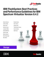
Figure 5-2 shows the basic concept of a thin-provisioned volume.
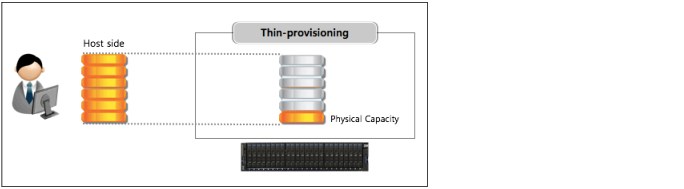
Figure 5-2 Thin-provisioned volume

Figure 5-3 Different kinds of volumes in DRP
In standard pools, thin-provisioned volumes are created based on capacity savings criteria. These properties are managed at the volume level. However, in DRPs, all the benefits of thin-provisioning are available to all the volumes that are assigned to the pool. For the thin-provisioned volumes in DRPs, you can configure compression and data deduplication on these volumes, which increases the capacity savings for the entire pool.
You can enhance capacity efficiency for thin-provisioned volumes by monitoring the hosts’ use of capacity. When the host indicates that the capacity is no longer needed, the space is released and can be reclaimed by the DRP. Standard pools do not have these functions.
Figure 5-4 shows the concepts of thin-provisioned volumes. These concepts are described next.

Figure 5-4 Thin-provisioned volume concepts
Real capacity defines how much disk space from a pool is allocated to a volume. Virtual capacity is the capacity of the volume that is reported to the hosts. A volume’s virtual capacity is larger than its real capacity.
Each system uses the real capacity to store data that is written to the volume and metadata that describes the thin-provisioned configuration of the volume. As more information is written to the volume, more of the real capacity is used. The system identifies read operations to unwritten parts of the virtual capacity and returns zeros to the server without the use of any real capacity.
Thin-provisioned volumes in a standard pool are available in two operating modes: autoexpand and noautoexpand. You can switch the mode at any time. Thin-provisioned volumes in a DRP always have autoexpand enabled.
If you select the autoexpand feature, IBM FlashSystem automatically adds a fixed amount of real capacity to the thin volume as required. Therefore, the autoexpand feature attempts to maintain a fixed amount of unused real capacity for the volume. We recommend the use of autoexpand by default to avoid volume offline issues.
This amount extra real capacity is known as the contingency capacity. The contingency capacity is initially set to the real capacity that is assigned when the volume is created. If the user modifies the real capacity, the contingency capacity is reset to be the difference between the used capacity and real capacity.
A volume that is created without the autoexpand feature (and therefore has a zero contingency capacity) goes offline when the real capacity is used. In this case, it must be expanded.
When creating a thin-provisioned volume with compression and deduplication that is enabled, you must be careful of out-of-space issues in the volume and pool where the volume is created. Set the warning threshold in the pools that contain thin-provisioned volumes, and in the volume.
|
Warning threshold: When you are working with thin-provisioned volumes, enable the warning threshold (by using email or an SNMP trap) in the storage pool. If the autoexpand feature is not used, you also must enable the warning threshold on the volume level. If the pool or volume runs out of space, the volume goes offline, which results in a loss of access.
|
If you do not want to be concerned with monitoring volume capacity, it is highly recommended that the autoexpand option is enabled. Also, when you create a thin-provisioned volume, you must specify the space that is initially allocated to it (-rsize option in the CLI) and the grain size.
By default, rsize (or real capacity) is set to 2% of the volume virtual capacity, and grain size is 256 KiB. These default values, with autoexpand enabled and warning disabled options, work in most scenarios. Some instances exist in which you might consider the use of different values to suit your environment.
Example 5-2 shows the command to create a volume with the suitable parameters.
Example 5-2 Creating thin-provisioned volume
superuser>mkvdisk -name VOL02 -mdiskgrp Pool1 -size 100 -unit gb -vtype striped -iogrp io_grp0 -rsize 2% -autoexpand -warning 0 -grainsize 256
Virtual Disk, id [53], successfully created
superuser>lsvdisk VOL02
id 53
name VOL02
.
lines removed for brevity
.
capacity 100.00GB
.
lines removed for brevity
.
used_capacity 0.75MB
real_capacity 2.02GB
free_capacity 2.01GB
overallocation 4961
autoexpand on
warning 0
grainsize 256
se_copy yes
.
lines removed for brevity
A thin-provisioned volume can be converted nondisruptively to a fully allocated volume, or vice versa. Figure 5-5 shows how to modify capacity savings of a volume. You can right-click the volume and select Modify Capacity Savings.

Figure 5-5 Modifying capacity savings of a volume nondisruptively
The fully allocated to thin-provisioned migration procedure uses a zero-detection algorithm so that grains that contain all zeros do not cause any real capacity to be used.
5.3.1 Compressed volumes
When you create volumes, you can specify compression as a method to save capacity for the volume. With compressed volumes, data is compressed as it is written to disk, which saves more space. When data is read to hosts, the data is decompressed.
|
Note: The volume compression attribute is independent of any compression that is performed by FlashCore Modules or any other compressing backend.
|
IBM FlashSystem support compressed volumes in a DRP only. DRPs also reclaims capacity that is not used by hosts if the host supports SCSI unmap commands. When these hosts issue SCSI unmap commands, a DRP reclaims the released capacity.
Compressed volumes in DRPs do not display their individual compression ratio. The pool used capacity before reduction indicates the total amount of data that is written to volume copies in the storage pool before data reduction occurs. The pool used capacity after reduction is the space that is used after thin provisioning, compression, and deduplication. This compression solution provides nondisruptive conversion between compressed and decompressed volumes.
If you are planning to virtualize volumes that are connected to your hosts directly from any storage subsystems, and you want an estimate of the space saving that likely is to be achieved, run the IBM Data Reduction Estimator Tool (DRET).
DRET tool is a command-line and host-based utility that can be used to estimate an expected compression rate for block devices. This tool also can evaluate capacity savings by using deduplication. For more information, see this IBM Support web page.
IBM FlashSystem also includes an integrated Comprestimator tool, which is available through the management GUI and command-line interface (CLI). If you are considering applying compression on noncompressed volumes in an IBM FlashSystem, you can use this tool to evaluate if compression generates enough capacity savings.
For more information, see 4.1.4, “Data reduction estimation tools” on page 125.
As shown in Figure 5-6, customize the Volume view to see the compression savings for a compressed volume, and estimated compression savings for a noncompressed volume that you are planning to migrate.

Figure 5-6 Customized view
5.3.2 Deduplicated volumes
Deduplication is a data reduction technique for eliminating duplicate copies of data. It can be configured with thin-provisioned and compressed volumes in a DRP for saving capacity.
The deduplication process identifies unique chunks of data (or byte patterns) and stores a signature of the chunk for reference when writing new data chunks. If the new chunk’s signature matches an existing signature, the new chunk is replaced with a small reference that points to the stored chunk. The same byte pattern can occur many times, which results in the amount of data that must be stored being greatly reduced.
If a volume is configured with deduplication and compression, data is deduplicated first and then, compressed. Therefore, deduplication references are created on the compressed data that is stored on the physical domain.
The scope of deduplication is all deduplicated volumes in the same pool, regardless of the volume’s preferred node or IO group.
Figure 5-7 shows the settings to create a compressed and deduplicated volume.

Figure 5-7 Creating deduplicated volumes
To create a thin-provisioned volume that uses deduplication, enter the command in the CLI that is shown in Example 5-3.
Example 5-3 Creating thin-provisioned volume with deduplication option
superuser>mkvolume -name dedup_test_01 -size 10 -unit gb -pool 0 -thin -deduplicated
Volume, id [55], successfully created
To create a compressed volume that uses deduplication, enter the command that is shown in Example 5-4.
Example 5-4 Creating compressed volume with deduplication option
superuser>mkvolume -name dedup_test_02 -size 10 -unit gb -pool 0 -compressed -deduplicated
Volume, id [56], successfully created
To maximize the space that is available for the deduplication database, the system distributes it between all nodes in the I/O groups that contain deduplicated volumes. Each node holds a distinct portion of the records that are stored in the database.
Depending on the data type stored on the volume, the capacity savings can be significant. Examples of use cases that typically benefit from deduplication are virtual environments with multiple virtual machines running the same operating system and backup servers.
In both cases, it is expected that multiple copies of identical files exist, such as components of the standard operating system or applications that are used in the organization. Conversely, data that is encrypted or compressed at the file system level does not benefit from deduplication because these operations were removed for redundancy.
If you want to evaluate if savings are realized by migrating a set of volumes to deduplicated volumes, you can use DRET. For more information about DRET, see 4.1.4, “Data reduction estimation tools” on page 125.
5.3.3 Thin provisioning considerations
Thin provisioning works best if the host limits writes to areas of the volume that store data. For example, if the host performs a low-level format of the entire volume, the host writes to the entire volume and no advantage is gained by using a thin provisioning volume over a fully allocated volume.
Consider the following properties of thin-provisioned volumes that are useful to understand for the rest of the section:
•When the used capacity first exceeds the volume warning threshold, an event is raised, which indicates that real capacity is required. The default warning threshold value is 80% of the volume capacity. To disable warnings, specify 0%.
•Compressed volumes include an attribute called decompressed used capacity (for standard pools) and used capacity before reduction (for a DRP). These volumes are the used capacities before compression or data reduction. They are used to calculate the compression ratio.
Thin provisioning and over-allocation
Because thin-provisioned volumes do not store the zero blocks, a storage pool is over-allocated only after the sum of all volume capacities exceeds the size of the storage pool.
Storage administrators likely think about the out-of-space problem. If enough capacity exists on disk to store fully allocated volumes, and you convert them to thin-provisioned volumes, enough space exists to store data (even if the servers writes to every byte of virtual capacity). Therefore, this issue is not going to be a problem for the short term, and you have time to monitor your system and understand how your capacity grows.
Monitoring capacity with thin-provisioned volumes
|
Note: It is critical that capacity be monitored when thin-provisioned or compressed volumes are used. Be sure to add capacity before running out of space.
|
If you run out of space on a volume or storage pool, the host that uses the affected volumes cannot perform new write operations to these volumes. Therefore, an application or database that is running on this host becomes unavailable.
In a storage pool with only fully allocated volumes, the storage administrator can easily manage the used and available capacity in the storage pool as its used capacity grows when volumes are created or expanded.
However, in a pool with thin-provisioned volumes, the used capacity can increase at any time if the host file system grows. For this reason, the storage administrator must consider capacity planning carefully. It is critical to put in place volume and pool capacity monitoring.
Tools, such as IBM Spectrum Control and Storage Insights, can display the capacity of a storage pool in real time and graph how it is growing over time. These tools are important because they are used to predict when the pool will run out of space.
IBM FlashSystem also alerts you by including an event in the event log when the storage pool reaches the configured threshold, which is called the warning level. The GUI sets this threshold to 80% of the capacity of the storage pool by default.
By using enhanced Call Home and Storage Insights, IBM now has the ability to monitor and flag systems that have low capacity. This ability can result in a support ticket being generated and the client being contacted.
What to do if you run out of space in a storage pool
You can use one or a combination of the following options that are available if a storage pool runs out of space:
•Contingency capacity on thin-provisioned volumes
If the storage pool runs out of space, each volume has its own contingency capacity, which is an amount of storage that is reserved by the volume and is sizable. Contingency capacity is defined by the real capacity parameter that is specified when the volume is created, which has a default value of 2%.
The contingency capacity protects the volume from going offline when its storage pool runs out of space by having the storage pool use this reserved space first. Therefore, you have some time to repair things before everything starts going offline.
If you want more safety, you might implement a policy of creating volumes with 10% of real capacity. Also, remember that you do not need to have the same contingency capacity for every volume.
|
Note: This protection likely solves most immediate problems. However, after you are informed that you ran out of space, a limited amount of time exists to react. You need a plan in place and well-understood about what to do next.
|
•Have unallocated storage on standby
You can always have spare drives or managed disks ready to be added to whichever storage pool runs out of space within only a few minutes. This capacity gives you some breathing room while you take other actions. The more drives or MDisks you have, the more time you must solve the problem.
•Sacrificial emergency space volume
Consider the use of a fully allocated sacrificial emergency space volume in each pool. If the storage pool is running out of space, you can delete or shrink this volume to quickly provide more available space in the pool.
•Move volumes
You can migrate volumes to other pools to free up space. However, data migration on IBM FlashSystem is designed to move slowly to avoid performance problems. Therefore, it might be impossible to complete this migration before your applications go offline.
•Policy-based solutions
No policy is going to solve the problem if you run out of space; however, you can use policies to reduce the likelihood of that ever happening to the point where you feel comfortable doing less of the other options.
You can use these types of policies for thin provisioning:
|
Note: The following policies use arbitrary numbers. These numbers are designed to make the suggested policies more readable. We do not provide any recommended numbers to insert into these policies because they are determined by business risk, and this consideration is different for every client.
|
– Manage free space such that enough free capacity always is available for your 10 largest volumes to reach 100% full without running out of free space.
– Never over-allocate more than 200%. That is, if you have 100 TB of capacity in the storage pool, the sum of the volume capacities in the same pool must not exceed 200 TB.
– Always start the process of adding capacity when the storage pool reaches 70% full.
Grain size
The grain size is defined when the thin-provisioned volume is created and can be set to 32 KB, 64 KB, 128 KB, or 256 KB (default). The grain size cannot be changed after the thin-provisioned volume is created.
Smaller granularities can save more space, but they have larger directories. If you select
32 KB for the grain size, the volume size cannot exceed 260,000 GB. Therefore, if you are not going to use the thin-provisioned volume as a FlashCopy source or target volume, use
256 KB by default to maximize performance.
32 KB for the grain size, the volume size cannot exceed 260,000 GB. Therefore, if you are not going to use the thin-provisioned volume as a FlashCopy source or target volume, use
256 KB by default to maximize performance.
Thin-provisioned volume copies in DRPs feature a grain size of 8 KB. This predefined value cannot be set or changed.
If you are planning to use thin provisioning with FlashCopy, remember that grain size for FlashCopy volumes can be only 64 KB or 256 KB. In addition, to achieve best performance, the grain size for the thin-provisioned volume and FlashCopy mapping must be same. For this reason, it is not recommended to use thin-provisioned volume in DRPS as a FlashCopy source or target volume.
|
Note: The use of thin-provisioned volumes in a DRP for FlashCopy is not recommended.
|
5.4 Mirrored volumes
By using volume mirroring, a volume can have two copies. Each volume copy can belong to a different pool and have different capacity reduction attributes. Each copy features the same virtual capacity as the volume. In the management GUI, an asterisk (*) indicates the primary copy of the mirrored volume. The primary copy indicates the preferred volume for read requests.
When a server writes to a mirrored volume, the system writes the data to both copies. When a server reads a mirrored volume, the system picks one of the copies to read. If one of the mirrored volume copies is temporarily unavailable (for example, because the storage system that provides the pool is unavailable), the volume remains accessible to servers. The system remembers which areas of the volume are written and resynchronizes these areas when both copies are available.
You can create a volume with one or two copies, and you can convert a non-mirrored volume into a mirrored volume by adding a copy. When a copy is added in this way, the system synchronizes the new copy so that it is the same as the existing volume. Servers can access the volume during this synchronization process.
You can convert a mirrored volume into a nonmirrored volume by deleting one copy or by splitting one copy to create a non-mirrored volume.
The volume copy can be any type: image, striped, or sequential. The volume copy can use thin-provisioning or compression to save capacity. If the copies are in DRPs, you can also use deduplication to the volume copies to increase the capacity savings.
If you are creating a volume, the two copies can use different capacity reduction attributes. However, to create a mirrored volume, both copies must be in a DRP. You can add a deduplicated volume copy in a DRP to a volume with a copy in a standard pool. You can use this method to migrate volume copies to data migration pools.
You can use mirrored volumes for the following reasons:
•Improving availability of volumes by protecting them from a single storage system failure.
•Providing concurrent maintenance of a storage system that does not natively support concurrent maintenance.
•Providing an alternative method of data migration with better availability characteristics. While a volume is migrated by using the data migration feature, it is vulnerable to failures on the source and target pool. Volume mirroring provides an alternative because you can start with a non-mirrored volume in the source pool, and then, add a copy to that volume in the destination pool.
When the volume is synchronized, you can delete the original copy that is in the source pool. During the synchronization process, the volume remains available, even if a problem occurs with the destination pool.
•Converting fully allocated volumes to use data reduction technologies, such as thin-provisioning, compression, or deduplication.
•Converting compressed or thin-provisioned volumes in standard pools to DRPs to improve capacity savings.
When a volume mirror is synchronized, a mirrored copy can become unsynchronized if it goes offline and write I/O requests must be processed, or if a mirror fast failover occurs. The fast failover isolates the host systems from temporarily slow-performing mirrored copies, which affect the system with a short interruption to redundancy.
|
Note: In standard-provisioned volumes, the primary volume formats before synchronizing to the volume copies. The -syncrate parameter on the mkvdisk command controls the format and synchronization speed.
|
You can create a mirrored volume by using the Mirrored option in the Create Volume window, as showing in Figure 5-8.

Figure 5-8 Mirrored volume creation
You can convert a non-mirrored volume into a mirrored volume by adding a copy, as shown in Figure 5-9.

Figure 5-9 Adding a volume copy
5.4.1 Write fast failovers
With write fast failovers, the system submits writes to both copies during processing of host write I/O. If one write succeeds and the other write takes longer than 10 seconds, the slower request times-out and ends. The duration of the ending sequence for the slow copy I/O depends on the backend from which the mirror copy is configured. For example, if the I/O occurs over the Fibre Channel network, the I/O ending sequence typically completes in 10 - 20 seconds.
However, in rare cases, the sequence can take more than 20 seconds to complete. When the I/O ending sequence completes, the volume mirror configuration is updated to record that the slow copy is now no longer synchronized. When the configuration updates finish, the write I/O can be completed on the host system.
The volume mirror stops by using the slow copy for 4 - 6 minutes; subsequent I/O requests are satisfied by the remaining synchronized copy. During this time, synchronization is suspended. Also, the volume’s synchronization progress shows less than 100% and decreases if the volume receives more host writes. After the copy suspension completes, volume mirroring synchronization resumes and the slow copy starts synchronizing.
If another I/O request times out on the unsynchronized copy during the synchronization, volume mirroring again stops by using that copy for 4 - 6 minutes. If a copy is always slow, volume mirroring attempts to synchronize the copy again every 4 - 6 minutes and another I/O timeout occurs.
The copy is not used for another 4 - 6 minutes and becomes progressively unsynchronized. Synchronization progress gradually decreases as more regions of the volume are written.
If write fast failovers occur regularly, an underlying performance problem can exist within the storage system that is processing I/O data for the mirrored copy that became unsynchronized. If one copy is slow because of storage system performance, multiple copies on different volumes are affected. The copies might be configured from the storage pool that is associated with one or more storage systems. This situation indicates possible overloading or other back-end performance problems.
When you run the mkvdisk command to create a volume, the mirror_write_priority parameter is set to latency by default. Fast failover is enabled. However, fast failover can be controlled by changing the value of the mirror_write_priority parameter on the chvdisk command. If the mirror_write_priority is set to redundancy, fast failover is disabled.
The system applies a full SCSI initiator-layer error recovery procedure (ERP) for all mirrored write I/O. If one copy is slow, the ERP can take up to 5 minutes. If the write operation is still unsuccessful, the copy is taken offline. Carefully consider whether maintaining redundancy or fast failover and host response time (at the expense of a temporary loss of redundancy) is more important.
|
Note: Mirrored volumes can be taken offline if no quorum disk is available. This behavior occurs because synchronization status for mirrored volumes is recorded on the quorum disk. To protect against mirrored volumes being taken offline, follow the guidelines for setting up quorum disks.
|
5.4.2 Read fast failovers
Read fast failovers affect how the system processes read I/O requests. A read fast failover determines which copy of a volume the system tries first for a read operation. The primary-for-read copy is the copy that the system tries first for read I/O.
The system submits a host read I/O request to one copy of a volume at a time. If that request succeeds, the system returns the data. If it is not successful, the system retries the request to the other copy volume.
With read fast failovers, when the primary-for-read copy goes slow for read I/O, the system fails over to the other copy. Therefore, the system tries the other copy first for read I/O during the following 4 - 6 minutes. After that attempt, the system reverts to read the original primary-for-read copy.
During this period, if read I/O to the other copy also is slow, the system reverts immediately. Also, if the primary-for-read copy changes, the system reverts to try the new primary-for-read copy. This issue can occur when the system topology changes or when the primary or local copy changes. For example, in a standard topology, the system normally tries to read the primary copy first. If you change the volume’s primary copy during a read fast failover period, the system reverts to read the newly set primary copy immediately.
The read fast failover function is always enabled on the system. During this process, the system does not suspend the volumes or make the copies out of sync.
5.4.3 Maintaining data integrity of mirrored volumes
Volume mirroring improves data availability by allowing hosts to continue I/O to a volume, even if one of the back-end storage systems fails. However, this mirroring does not affect data integrity. If either of the back-end storage systems corrupts the data, the host is at risk of reading that corrupted data in the same way as for any other volume.
Therefore, before you perform maintenance on a storage system that might affect the data integrity of one copy, it is important to check that both volume copies are synchronized. Then, remove that volume copy before you begin the maintenance.
5.5 HyperSwap volumes
HyperSwap volumes create copies on two separate sites for systems that are configured with HyperSwap topology. Data that is written to a HyperSwap volume is automatically sent to both copies so that either site can provide access to the volume if the other site becomes unavailable.
HyperSwap is a system topology that enables Disaster Recovery (DR) and high availability between I/O groups at different locations. Before you configure HyperSwap volumes, the system topology must be configured for HyperSwap and sites must be defined. Figure 5-10 shows an overall view of IBM FlashSystem HyperSwap that is configured with two sites.

Figure 5-10 Overall HyperSwap diagram
In the management GUI, HyperSwap volumes are configured by specifying volume details, such as quantity, capacity, name, and the method for saving capacity. As with basic volumes, you can choose compression or thin-provisioning to save capacity on volumes.
For thin-provisioning or compression, you can also select to use deduplication for the volume that you create. For example, you can create a compressed volume that also uses deduplication to remove duplicated data.
The method for capacity savings applies to all HyperSwap volumes and copies that are created. The volume location displays the site where copies are located, based on the configured sites for the HyperSwap system topology. For each site, specify a pool and I/O group that are used by the volume copies that are created on each site. If you select to deduplicate volume data, the volume copies must be in DRPs on both sites.
The management GUI creates an HyperSwap relationship and change volumes automatically. HyperSwap relationships manage the synchronous replication of data between HyperSwap volume copies at the two sites.
If your HyperSwap system supports self-encrypting drives and the base volume is fully allocated in a DRP, the corresponding change volume is created with compression enabled. If the base volume is in a standard pool, the change volume is created as a thin-provisioned volume.
You can specify a consistency group that contains multiple active-active relationships to simplify management of replication and provide consistency across multiple volumes. A consistency group is commonly used when an application spans multiple volumes. Change volumes maintain a consistent copy of data during resynchronization. Change volumes allow an older copy to be used for DR if a failure occurred on the up-to-date copy before resynchronization completes.
You can also use the mkvolume command line to create a HyperSwap volume. The command also defines pools and sites for HyperSwap volume copies and creates the active-active relationship and change volumes automatically. If your HyperSwap system supports self-encrypting drives and the base volume is fully allocated in a DRP, the corresponding change volume is created with compression enabled. If the base volume is in a standard pool, the change volume is created as a thin-provisioned volume.
You can see the relationship between the Master and Auxiliary volume in a 2-site HyperSwap topology in Figure 5-11.

Figure 5-11 Master and Auxiliary volumes
For more information about HyperSwap volumes, see 7.3, “HyperSwap Volumes” on page 364.
5.6 VMware virtual volumes
The IBM FlashSystem supports VMware vSphere Virtual Volumes, sometimes referred to as VVols, which allows VMware vCenter to automate the management of system objects, such as volumes and pools.
You can assign ownership of Virtual Volumes to IBM Spectrum Connect by creating a user with the VASA Provider security role. IBM Spectrum Connect provides communication between the VMware vSphere infrastructure and the system.
Although you can complete specific actions on volumes and pools that are owned by the VASA Provider security role, IBM Spectrum Connect retains management responsibility for Virtual Volumes.
When virtual volumes are enabled on the system, a utility volume is created to store metadata for the VMware vCenter applications. You can select a pool to provide capacity for the utility volume. With each new volume that is created by the VASA provider, VMware vCenter defines a few kilobytes of metadata that are stored on the utility volume.
The utility volume can be mirrored to a second storage pool to ensure that the failure of a storage pool does not result in loss of access to the metadata. Utility volumes are exclusively used by the VASA provider and cannot be deleted or mapped to other host objects.
|
Note: The utility volume cannot be created in a DRP.
|
Figure 5-12 provides a high-level overview of the key components that enable the VVols management framework.

Figure 5-12 Overview of the key components of VMware environment
You can also use data copy through VMware vSphere Storage APIs Array Integration (VAAI), as shown in Figure 5-13.
Figure 5-13 VMware vSphere Storage APIs Array Integration (VAAI)
The following are prerequisites must be met before configuring Virtual Volumes:
•An IBM Spectrum Connect must be set up.
•VMware vSphere ESXi hosts and vCenter running version 6.0 or later.
•The Network Time Protocol (NTP) server is configured on IBM FlashSystem and IBM Spectrum Connect.
To start using Virtual Volumes, complete the following steps on the IBM FlashSystem before you configure any settings within the IBM Spectrum Connect server:
1. Enable Virtual Volumes on the IBM FlashSystem:
a. In the management GUI, click Settings → System → VVOL and select On.
b. Select the pool to where the utility volume is stored. If possible, store a mirrored copy of the utility volume in a second storage pool that is in a separate failure domain. The utility volume cannot be created in a DRP.
c. Create a user for IBM Spectrum Connect to communicate with the IBM FlashSystem, as shown in Figure 5-14 on page 220.

Figure 5-14 Enable VVOL window
2. Create the user account for the IBM Spectrum Connect and the user group with VMware vSphere API for Storage Awareness (VASA) provider role, if they were not set in the previous step:
a. Create a user group by clicking Access → Users by Group → Create User Group. Enter the user group name, select VASA Provider for the role and click Create.
b. Create the user account by clicking Access → Users by Group, select the user group that was created in the previous step, and click Create User. Enter the name of the user account, select the user group with VASA Provider role, enter a valid password for the user, and click Create.
3. For each ESXi host server to use Virtual Volumes, create a host object:
a. In the management GUI, select Hosts → Hosts → Add Host.
b. Enter the name of the ESXi host server, enter connection information, select VVOL for the host type and then, click Add Host.
c. If the ESXi host was previously configured, the host type can be changed by modifying the ESXi host type.
|
Note: The user account with VASA Provider role is used by only the IBM Spectrum Connect server to access the IBM FlashSystem and to run the automated tasks that are required for Virtual Volumes. Users must not directly log in to the management GUI or CLI with this type of account and complete system tasks, unless they are directed to by IBM Support.
|
5.7 Cloud volumes
A cloud volume is any volume that is enabled for transparent cloud tiering. After transparent cloud tiering is enabled on a volume, point-in-time copies or snapshots can be created and copied to cloud storage that is provided by a cloud service provider. These snapshots can be restored to the system for DR purposes. Before you create cloud volumes, a valid connection to a supported cloud service provider must be configured.
With transparent cloud tiering, the system supports connections to cloud service providers and the creation of cloud snapshots of any volume or volume group on the system. Cloud snapshots are point-in-time copies of volumes that are created and transferred to cloud storage that is managed by a cloud service provider.
A cloud account defines the connection between the system and a supported cloud service provider. It also must be configured before data can be transferred to or restored from the cloud storage. After a cloud account is configured with the cloud service provider, you determine which volumes you want to create cloud snapshots of and enable transparent cloud tiering on those volumes.
Figure 5-15 shows an example of IBM Transparent Cloud Tiering.

Figure 5-15 Transparent Cloud Tiering example
A cloud account is an object on the system that represents a connection to a cloud service provider by using a particular set of credentials. These credentials differ depending on the type of cloud service provider that is being specified. Most cloud service providers require the host name of the cloud service provider and an associated password. Some cloud service providers also require certificates to authenticate users of the cloud storage. Public clouds use certificates that are signed by well-known certificate authorities.
Private cloud service providers can use a self-signed certificate or a certificate that is signed by a trusted certificate authority. These credentials are defined on the cloud service provider and passed to the system through the administrators of the cloud service provider.
A cloud account defines whether the system can successfully communicate and authenticate with the cloud service provider by using the account credentials.
If the system is authenticated, it can access cloud storage to copy data to the cloud storage or restore data that is copied to cloud storage back to the system. The system supports one cloud account to a single cloud service provider. Migration between providers is not supported.
The system supports IBM Cloud, OpenStack Swift and Amazon S3 cloud service providers.
5.7.1 Transparent cloud tiering configuration limitations and rules
Consider the following limitations and rules regarding transparent cloud tiering:
•One cloud account per system.
•A maximum of 1024 volumes can have cloud-snapshot enabled volumes.
•The maximum number of active snapshots per volume is 256.
•The maximum number of volume groups is 512.
•Cloud volumes cannot be expanded or shrunk.
•A volume cannot be configured for a cloud snapshot if any of the following conditions exist:
– The volume is part of a Remote Copy relationship (Metro Mirror, Global Mirror, or active-active) master, auxiliary, or change volume. This configuration prevents the cloud snapshot from being used with HyperSwap volumes.
– The volume is a VMware vSphere Virtual Volumes volume, including IBM FlashCopy owned volumes that are used internally for Virtual Volumes restoration functions.
– The volume is:
• A file system volume
• Associated with any user-owned FlashCopy maps
• A mirrored volume with copies in different storage pools
• Being migrated between storage pools
•A volume cannot be enabled for cloud snapshots if the cloud storage is set to import mode.
•A volume cannot be enabled for cloud snapshots if the maximum number of cloud volumes exists. The maximum number of cloud volumes on the system is 1024. If the system exceeds this limit, you can disable cloud snapshots on a cloud volume and delete its associated snapshots from the cloud storage to accommodate snapshots on new cloud volumes.
•A volume cannot be used for a restore operation if it meets any of the following criteria:
– A Virtual Volume, including FlashCopy volumes that are used internally for Virtual Volumes restoration functions
– A file system volume
– Part of a Remote Copy relationship (Metro Mirror, Global Mirror, or active-active) master, auxiliary, or change volume
•A volume that is configured for backup or is being used for restoration cannot be moved between I/O groups.
•Only one operation (cloud snapshot, restore, or snapshot deletion) is allowed at a time on a cloud volume.
•Cloud volume traffic is allowed only through management interfaces (1 G or 10 G).
5.7.2 Restoring to the production volume
This process is used to restore a snapshot version to the production volume, which is the original volume from which the snapshots were created. After the restore operation completes, the snapshot version completely replaces the current data that exists on production volume. During the restore operation, the production volume goes offline until it completes. Data is not fully restored to the production volume until the changes are committed.
5.7.3 Restore to a new volume
If you do not want to have the production volume offline for the restore, you can restore a cloud snapshot to a new volume. The production volume remains online and host operations are not disrupted.
When the snapshot version is restored to a new volume, you can use the restored data independently of the original volume from which the snapshot was created. If the new volume exists on the system, the restore operation uses the unique identifier (UID) of the new volume.
If the new volume does not exist on the system, you must choose whether to use the UID from the original volume or create a UID. If you plan to use the new volume on the same system, use the UID that is associated with the snapshot version that is being restored.
5.8 Volume migration
Migrating an image mode volume to managed mode volume or vice versa is done by migrating a volume from one storage pool to another. A non-image mode volume also can be migrated to a different storage pool.
When migrating from image to managed or vice versa, the command varies, as listed in Table 5-1.
Table 5-1 Migration types and associated commands
|
Storage pool-to-storage pool type
|
Command
|
|
Managed-to-managed or
Image-to-managed |
migratevdisk
|
|
Managed-to-image or
Image-to-image |
migratetoimage
|
Migrating a volume from one storage pool to another is nondisruptive to the host application that uses the volume. Depending on the workload of IBM FlashSystem, performance might be slightly affected.
The migration of a volume from one storage pool to another storage pool by using migratevdisk command is allowed only if both storage pools feature the same extent site. Volume mirroring can be used if a volume must be migrated from one storage pool to another storage pool with different extent sizes.
5.8.1 Image-type to striped-type volume migration
When you are migrating storage into the IBM FlashSystem, the storage is brought in as image-type volumes, which means that the volume is based on a single MDisk. The CLI command that can be used is migratevdisk.
Example 5-5 shows the migratevdisk command that can be used to migrate an image-type volume to a striped-type volume. The command also can be used to migrate a striped-type volume to a striped-type volume.
Example 5-5 The migratevdisk command
superuser> migratevdisk -mdiskgrp MDG1DS4K -threads 4 -vdisk Migrate_sample
This command migrates the volume Migrate_sample to the storage pool MDG1DS4K, and uses four threads when migrating. Instead of the use of the volume name, you can use its ID number.
You can monitor the migration process by using the lsmigrate command, as shown in Example 5-6.
Example 5-6 Monitoring the migration process
superuser> lsmigrate
migrate_type MDisk_Group_Migration
progress 0
migrate_source_vdisk_index 3
migrate_target_mdisk_grp 2
max_thread_count 4
migrate_source_vdisk_copy_id 0
5.8.2 Migrating to image-type volume
An image-type volume is a direct, “straight-through” mapping to one image mode MDisk. If a volume is migrated to another MDisk, the volume is represented as being in managed mode during the migration (because it is striped on two MDisks).
It is represented only as an image-type volume after it reaches the state where it is a straight-through mapping. An image-type volume cannot be expanded.
Image-type disks are used to migrate data to an IBM FlashSystem and migrate data out of virtualization. In general, the reason for migrating a volume to an image type volume is to move the data on the disk to a non-virtualized environment.
If the migration is interrupted by a cluster recovery, the migration resumes after the recovery completes.
The migratetoimage command migrates the data of a user-specified volume by consolidating its extents (which might be on one or more MDisks) onto the extents of the target MDisk that you specify. After migration is complete, the volume is classified as an image type volume, and the corresponding MDisk is classified as an image mode MDisk.
The MDisk that is specified as the target must be in an unmanaged state at the time that the command is run. Running this command results in the inclusion of the MDisk into the user-specified storage pool.
|
Remember: This command cannot be used if the source volume copy is in a child pool or if the target MDisk group that is specified is a child pool. This command does not work if the volume is fast formatting.
|
The migratetoimage command fails if the target or source volume is offline. Correct the offline condition before attempting to migrate the volume.
If the volume (or volume copy) is a target of a FlashCopy mapping with a source volume in an active-active relationship, the new managed disk group must be in the same site as the source volume. If the volume is in an active-active relationship, the new managed disk group must be in the same site as the source volume. Also, the site information for the MDisk being added must be well defined and match the site information for other MDisks in the storage pool.
|
Note: You cannot migrate a volume or volume image between storage pools if cloud snapshot is enabled on the volume.
|
An encryption key cannot be used when migrating an image mode MDisk. To use encryption (when the MDisk has an encryption key), the MDisk must be self-encrypting before configuring storage pool.
The migratetoimage command is useful when you want to use your system as a data mover. For more information about the requirements and specifications for the migratetoimage command, see this IBM Documentation web page.
5.8.3 Migrating with volume mirroring
Volume mirroring also offers the ability to migrate volumes between storage pools with different extent sizes.
Complete the following steps to migrate volumes between storage pools:
1. Add a copy to the target storage pool.
2. Wait until the synchronization is complete.
3. Remove the copy in the source storage pool.
To migrate from a thin-provisioned volume to a fully allocated volume, the process is similar:
1. Add a target fully allocated copy.
2. Wait for synchronization to complete.
3. Remove the source thin-provisioned copy.
In both cases, if you set the autodelete option to yes when creating the volume copy, the source copy is automatically deleted, and you can skip the third step in both processes. The preferred practice on this type of migration is to try not to overload the systems with a high syncrate or with too many migrations at the same time.
The syncrate parameter specifies the copy synchronization rate. A value of zero prevents synchronization. The default value is 50. The supported -syncrate values and their corresponding rates are listed in Table 5-2.
Table 5-2 Sample syncrate values
|
User-specified syncrate attribute value
|
Data copied per second
|
|
01 - 10
|
128 KB
|
|
11 - 20
|
256 KB
|
|
21 - 30
|
512 KB
|
|
31 - 40
|
1 MB
|
|
41 - 50
|
2 MB
|
|
51 - 60
|
4 MB
|
|
61 - 70
|
8 MB
|
|
71 - 80
|
16 MB
|
|
81 - 90
|
32 MB
|
|
91 - 100
|
64 MB
|
|
101 - 110
|
128 MB
|
|
111 - 120
|
256 MB
|
|
121 - 130
|
512 MB
|
|
131 - 140
|
1 GB
|
|
141 - 150
|
2 GB
|
We recommend modifying syncrate after monitoring overall bandwidth and latency. Then, if the performance is not affected on migration, increase the syncrate to complete within the allotted time.
You can also use volume mirroring when you migrate a volume from a non-virtualized storage device to IBM FlashSystem. As you can see in Figure 5-16, you first must attach the storage to IBM FlashSystem by using the virtualization solution, which requires some downtime because hosts start to access the volumes through IBM FlashSystem.

Figure 5-16 Migration with volume mirroring
After the storage is correctly attached to IBM FlashSystem, map the image-type volumes to the hosts so the host recognizes volumes as though they were accessed through the non-virtualized storage device. Then, you can restart applications.
After that process completed, you can use volume mirroring to migrate the volumes to a storage pool with managed MDisks, which creates striped-type copies of each volume in this target pool. Data synchronization in the volume copies then starts in the background.
For more information, see this IBM Documentation web page.
5.8.4 Migration from standard pools to Data Reduction Pools
If you want to migrate volumes to DRP, you can move them with volume mirroring between a standard pool and DRP. Hosts I/O operations are not disrupted during migration.
Figure 5-17 shows two examples of how you can use volume mirroring to convert volumes to a different type or migrate volumes to a different type of pool.

Figure 5-17 Converting volumes with volume mirroring
You can also move compressed or thin-provisioned volumes in standard pools to DRPs to simplify management of reclaimed capacity. The DRP tracks the unmap operations of the hosts and reallocates capacity automatically. The system supports volume mirroring to create a copy of the volume in a new DRP. This method creates a copy of the volume in a new DRP and does not disrupt host operations.
Deleting a volume copy in a DRP is a background task and can take a significant amount of time. During the deletion process, the deleting copy is still associated with the volume and a new volume mirror cannot be created until the deletion is complete. If you want to use volume mirroring again on the same volume without waiting for the delete, split the copy to be deleted to a new volume before deleting it.
5.8.5 Migrating a volume between systems nondisruptively
With nondisruptive system migration, storage administrators can migrate volumes from one IBM Spectrum Virtualize system to another without any application downtime. This function supports several use cases. For example, you can use this function to balance the load between multiple systems or to update and decommission hardware.
You can also migrate data between node-based systems and enclosure-based systems. Unlike replication remote-copy types, nondisruptive system migration does not require a Remote Mirroring license before you can configure a remote-copy relationship that is used for migration.
There are some configuration and host operating system restrictions that are documented in the Configuration Limits and Restrictions document under Volume Mobility.
Prerequisites
The following prerequisites must be met for nondisruptive system migration:
•Both systems are running 8.4.2 or later.
•A Fibre Channel or IP partnership exists between the two systems that you want to migrate volumes between. The maximum supported round-trip time (RTT) between the two systems is 3 milliseconds. Ensure that the partnership has sufficient bandwidth to support the write throughput for all the volumes you are migrating. For more information, see mkfcpartnership command for creating Fibre Channel partnerships and mkippartnership command for creating IP partnerships.
•Any hosts that are mapped to volumes that you are migrating are correctly zoned to both systems. Hosts must appear in an online state on both systems.
Using the management GUI
Complete the following steps to configure volume migration by using the GUI:
1. On the source system, select Volumes → Volumes. On the Volumes page, identify the volumes that you want to migrate and record of the volume name and capacity.
2. On the target system, select Volumes → Volumes and select Create Volume. Create the target volume within the appropriate storage tier with the same capacity as the source volume.
3. On the source system, select Copy Services → Remote Copy.
4. Select Independent Relationship.
5. Select Create Relationship.
6. On the Create Relationship page, select Non-disruptive System Migration.
7. Ensure that the auxiliary volume location specifies the system that you want to migrate to, select Next.
8. Select the Master and Auxiliary volumes to use in the relationship.
|
Note: The volumes must be the same size. If the GUI window does not show the expected auxiliary volume, check the size by running the lsvdisk -unit b <volume name or id> command.
|
9. Select Yes to start the copy. Click Finish.
10. In the management GUI, select Copy Services → Remote Copy → Independent Relationship. Wait until the migration relationship that you created displays the Consistent Synchronized state.
|
Note: Data is copied to the target system at the lowest of partnership background copy rate or relationship bandwidth. The relationship bandwidth default is 25 MBps per relationship and can be increased by running the chsystem -relationshipbandwidthlimit <new value in MB> command if needed.
|
11. Create host mappings to the auxiliary volumes on the remote system. Ensure that all auxiliary volumes are mapped to the same hosts that were previously mapped to the master volumes on the older system.
12. Ensure that the HBAs in all hosts that are mapped to the volume are rescanned to ensure that all new paths are detected to the auxiliary volumes. Record the current path states on any connected hosts. Identify the WWPNs used for the active and standby (ghost) paths.
13. In the management GUI, select Copy Services → Remote Copy → Independent Relationship. Right-click the migration relationship and select Switch Direction. This action reverses the copy direction of the relationship and switches the active and standby paths, which result in all host I/O being directed to the new volume.
14. Validate that all hosts use the new paths to the volume by verifying that the paths that were reporting as standby (or ghost) are now reporting active. Verify that all previously active paths are now reporting standby (or ghost).
|
Note: Do not proceed if the added standby paths are not visible on the host. Standby paths might be listed under a different name on the host, such as “ghost” paths. Data access can be affected if all standby paths are not visible to the hosts when the direction is switched on the relationship.
|
15. Validate that all hosts use the target volume for I/O and verify that no issues exist.
16. On the original source system that was used in the migration, select the Hosts → Hosts. Right-click the hosts and select Unmap Volumes. Verify the number of volumes that are being unmapped and then, select Unmap.
17. On the original source system, select Volumes → Volumes. Right-click the volumes and select Delete. Verify the number of volumes that are being deleted and select Continue.
The volume migration process is complete.
Using the command-line interface
Perform the following steps to configure volume migration by using the CLI:
1. On the source system, enter the lsvdisk command to determine all the volumes that you want to migrate to the target system.
In the results, record the name, ID, and capacity for each volume that you want to migrate to the target system.
2. On the target system, create volumes for each volume that you want to migrate, ensuring that you create the volume with the same capacity as the source volume; for example,
mkvolume -pool 0 -size 1000 -unit gb.
mkvolume -pool 0 -size 1000 -unit gb.
3. On the source system, enter the following command to create a relationship for migration:
mkrcrelationship -master sourcevolume -aux targetvolume -cluster system2 -migration -name migrationrc, where sourcevolume is the name or ID of the master volume on the source system and targetvolume is the name or ID of the auxiliary volume that you created on the target system.
mkrcrelationship -master sourcevolume -aux targetvolume -cluster system2 -migration -name migrationrc, where sourcevolume is the name or ID of the master volume on the source system and targetvolume is the name or ID of the auxiliary volume that you created on the target system.
The -migration flag indicates that the remote copy relationship can be used to migrate data between the two systems defined in the partnership only.
Optionally, you can specify a name with the -name parameter. In this example, migrationrc is the name of the relationship. If no name is specified, an identifier is assigned to the relationship.
4. On the source system, start the relationship by entering the running the
startrcrelationship migrationrc command, where migrationrc is the name of the relationship.
startrcrelationship migrationrc command, where migrationrc is the name of the relationship.
5. Verify that the state of the relationship is consistent_synchronized, by entering the lsrcrelationship migrationrc command, where migrationrc is the name of the relationship. In the results that display, ensure that the state is consistent_synchronized.
|
Attention: Do not proceed until the relationship is in the consistent_synchronized state.
|
Depending on the amount of data that is being migrated, the process can take some time.
|
Note: Data is copied to the target system at the lowest of partnership background copy rate or relationship bandwidth. The relationship bandwidth default is 25 MBps per relationship and can be increased by running the chsystem -relationshipbandwidthlimit <new value in MB> command, if needed.
|
6. After the relationship is in the consistent_synchronized state, create host mappings to the auxiliary volumes on the target system by entering the mkvdiskhostmap -host host1 targetvolume command, where targetvolume is the name of the auxiliary volume on the target system. Ensure that all auxiliary volumes are mapped to the same hosts that were previously mapped to the master volumes on the source system.
7. On all hosts, ensure that the HBAs are mapped to the volume are rescanned to ensure that all new paths are detected to the auxiliary volumes. Record the current path states on any connected hosts. Identify the WWPNs used for the active and standby (ghost) paths.
|
Attention: Do not proceed if the added standby paths are not visible on the host. Standby paths might be listed under a different name on the host, such as “ghost” paths. Data access can be affected if all standby paths are not visible to the hosts when the direction is switched on the relationship.
|
8. Switch the direction of the relationship so the auxiliary volume on the target system becomes the primary source for host I/O operations be entering the switchrcrelationship -primary aux migrationrc command, where migrationrc indicates the name of the relationship. This command reverses the copy direction of the relationship and switches the active and standby paths, which result in all host I/O being directed to the auxiliary volume.
9. Validate that all hosts use the new paths to the volume by verifying that the paths previously reporting as standby (or ghost) are now reporting active.
10. Verify that all previously active paths are now reporting standby (or ghost).
11. Validate that all hosts use the target volume for I/O and verify that no issues exist.
12. On the original source system, unmap hosts from the original volumes by entering the rmvdiskhostmap -host host1 sourcevolume command, where sourcevolume is the name of the original volume that was migrated.
13. On the original source system, delete the original source volumes by entering the rmvolume sourcevolume command, where sourcevolume is the name of the original volume that was migrated.
The migration process is now complete.
5.9 Preferred paths to a volume
When a volume is created, it is assigned to an I/O group and assigned a preferred node. The preferred node is the node that normally processes I/Os for the volume. The primary purposes of a preferred node are load balancing and determine which node destages writes to the backend storage.
Preferred node assignment is normally automatic. The system selects the node in the I/O group that includes the fewest volumes. However, the preferred node can be specified or changed, if needed.
All modern multipathing drivers support Asymmetric Logical Unit Access (ALUA). This access allows the storage to mark certain paths as preferred (paths to the preferred node). ALUA multipathing drivers honor preferred pathing and send I/O to only the other node if the preferred node is not accessible.
Figure 5-18 shows write operations from a host to two volumes with different preferred nodes.

Figure 5-18 Write operations from a host
When debugging performance problems, it can be useful to review the Non-Preferred Node Usage Percentage metric in IBM Spectrum Control or IBM Storage Insights. I/O to the nonpreferred node might cause performance problems for the I/O group and can be identified on these tools.
For more information about this performance metric and more in IBM Spectrum Control, see this IBM Documentation web page.
5.10 Moving a volume between I/O groups and nodes
To balance the workload across I/O groups and nodes, you can move volumes between I/O groups and nodes.
The change of preferred node of a volume within an I/O group or to another I/O group is a nondisruptive process.
5.10.1 Changing the preferred node of a volume within an I/O group
Changing the preferred node within an I/O group can be done with concurrent I/O. However, it can lead to some delay in performance and in the case of some specific operating systems or applications, they might detect some timeouts.
This operation can be done by using the CLI and GUI; however, if you have only one I/O group, this operation is not possible by using the GUI. To change the preferred node within an I/O group by using CLI, use the movevdisk -node <node_id or node_name> <vdisk_id or vdisk_name> command.
5.10.2 Moving a volume between I/O groups
When moving a volume between I/O groups, it is recommended that the system chooses the volume preferred node in the new I/O group. However, it is possible to manually set the preferred node during this operation by using the GUI and CLI.
Some limitations exist in to moving a volume across I/O groups, which is named Non-Disruptive Volume Move (NDVM). These limitations are mostly in Host Cluster environments, and you can check the compatibility at the IBM SSIC website.
|
Note: These migration tasks can be nondisruptive if performed correctly and the hosts that are mapped to the volume support NDVM. The cached data that is held within the system must first be written to disk before the allocation of the volume can be changed.
|
Modifying the I/O group that services the volume can be done concurrently with I/O operations if the host supports nondisruptive volume move. It also requires a rescan at the host level to ensure that the multipathing driver is notified that the allocation of the preferred node changed and the ports by which the volume is accessed changed. This rescan can be done in the situation where one pair of nodes becomes over-used.
If any host mappings are available for the volume, the hosts must be members of the target I/O group or the migration fails.
Verify that you created paths to I/O groups on the host system. After the system successfully adds the new I/O group to the volume’s access set and you moved the selected volumes to another I/O group, detect the new paths to the volumes on the host.
The commands and actions on the host vary depending on the type of host and the connection method used. These steps must be completed on all hosts to which the selected volumes are currently mapped.
|
Note: If the selected volume is performing quick initialization, this wizard is unavailable until quick initialization is complete.
|
5.11 Volume throttling
Volume throttling effectively throttles the number of I/O operations per second (IOPS) or bandwidth (MBps) that can be achieved to and from a specific volume. You might want to use I/O throttling if you have a volume that has an access pattern that adversely affects the performance of other volumes.
For example, volumes that are used for backup or archive operations can have I/O intensive workloads, potentially taking bandwidth from production volumes. Volume throttle can be used to limit I/Os for these types of volumes so that I/O operations for production volumes are not affected.
Figure 5-19 shows the example of volume throttling.

Figure 5-19 Volume throttling for each LUNs
When deciding between using IOPS or bandwidth as the I/O governing throttle, consider the disk access pattern of the application. Database applications often issue large amounts of I/O, but they transfer only a relatively small amount of data. In this case, setting an I/O governing throttle that is based on MBps does not achieve the expected result. Therefore, it is better to set an IOPS limit.
However, a streaming video application often issues a small amount of I/O, but it transfers large amounts of data. In contrast to the database example, defining an I/O throttle based in IOPS does not achieve a good result. For a streaming video application, it is better to set an MBps limit.
You can edit the throttling value in the menu, as shown in Figure 5-20.

Figure 5-20 Volume throttling
Figure 5-21 shows both bandwidth and IOPS parameter that can be set.

Figure 5-21 Edit bandwidth and IOPS limit
Throttling at a volume level can be set by using the following commands:
•mkthrottle
This command is used to set I/O throttles for volumes that use this command. It must be used with -type vdisk parameter, followed by -bandwidth bandwidth_limit_in_mbdisk or-iops iops_limit to define MBps and IOPS limits.
•chvdisk
When used with -rate throttle_rate parameter, this command specifies the IOPS and MBps limits. The default throttle_rate units are I/Os. To change the throttle_rate units to megabits per second (MBps), specify the -unitmb parameter. If throttle_rate value is zero, the throttle rate is disabled. By default, the throttle_rate parameter
is disabled.
is disabled.
|
Note: The mkthrottle command can be used to create throttles for volumes, hosts, host clusters, pools, or system offload commands.
|
When the IOPS limit is configured on a volume and it is smaller than 100 IOPS, the throttling logic rounds it to 100 IOPS. Even if throttle is set to a value smaller than 100 IOPS, the throttling occurs at 100 IOPS.
After any of the commands that were described thus far are used to set volume throttling, a throttle object is created. Then, you can list your created throttle objects by using the lsthrottle command and change their parameters with the chthrottle command. Example 5-7 shows some command examples.
Example 5-7 Throttle commands example
superuser>mkthrottle -type vdisk -bandwidth 100 -vdisk Vol01
Throttle, id [0], successfully created.
superuser>lsthrottle
throttle_id throttle_name object_id object_name throttle_type IOPs_limit bandwidth_limit_MB
0 throttle0 52 Vol01 vdisk 100
superuser>chthrottle -iops 1000 throttle0
superuser>lsthrottle
throttle_id throttle_name object_id object_name throttle_type IOPs_limit bandwidth_limit_MB
0 throttle0 52 Vol01 vdisk 1000 100
superuser>lsthrottle throttle0
id 0
throttle_name throttle0
object_id 52
object_name Vol01
throttle_type vdisk
IOPs_limit 1000
bandwidth_limit_MB 100
|
Note: The throttle reduces IOPS or bandwidth by adding latency as a resource approaches a defined throttle. This increased response time is observable in performance monitoring tools.
|
For more information and the procedure to set volume throttling, see IBM Documentation.
5.12 Volume cache mode
Cache mode in IBM FlashSystem determines whether read and write operations are stored in cache. For each volume, one of the following cache modes can be used:
•readwrite (enabled)
All read and write I/O operations that are performed by the volume are stored in cache. This default cache mode is used for all volumes. A volume or volume copy that is created from a DRP must have a cache mode of readwrite.
When you create a thin provisioned volume, set the cache mode to readwrite to maximize performance. If you set the mode to none, the system cannot cache the thin-provisioned metadata and performance is decreased. In a DRP, a thin-provisioned or compressed volume copy setting cannot be created for the cache mode that is different than readwrite.
•readonly
All read I/O operations that are performed by the volume are stored in cache.
•none (disabled)
All read and write I/O operations that are performed by the volume are not stored in cache.
By default, when a volume is created, the cache mode is set to readwrite. Disabling cache can affect performance and increase read and write response time.
Figure 5-22 shows write operation behavior when volume cache is activated (readwrite).

Figure 5-22 Cache activated
Figure 5-23 shows a write operation behavior when volume cache is deactivated (none).

Figure 5-23 Cache deactivated
In most cases, the volume with readwrite cache mode is recommended because disabling cache for a volume can result in performance issues to the host. However, some specific scenarios exist in which it is recommended to disable the readwrite cache.
You might use cache-disabled (none) volumes when you have Remote Copy or FlashCopy in a backend storage controller, and these volumes are virtualized in IBM FlashSystem devices as image VDisks. Another possible use of a cache-disabled volume is when intellectual capital is in copy services automation scripts. Keep the use of cache-disabled volumes to minimum for normal workloads.
You can also use cache-disabled volumes to control the allocation of cache resources. By disabling the cache for specific volumes, more cache resources are available to cache I/Os to other volumes in the same I/O group. An example of this use is a non-critical application that uses volumes in MDisks from all-flash storage.
|
Note: Volumes with readwrite cache enabled is recommended.
|
By default, volumes are created with cache mode enabled (read/write); however, you can specify the cache mode when the volume is created by using the -cache option.
The cache mode of a volume can be concurrently changed (with I/O) by using the chvdisk command or GUI, and selecting Volumes → Volumes → Actions → Cache Mode. Figure 5-24 shows editing cache mode for a volume.

Figure 5-24 Edit cache mode
The command line does not fail I/O to the user, and the command must be allowed to run on any volume. If used correctly without the -force flag, the command does not result in a corrupted volume. Therefore, the cache must be flushed and you must discard cache data if the user disables cache on a volume.
Example 5-8 shows an image volume VDISK_IMAGE_1 that changed the cache parameter after it was created.
Example 5-8 Changing the cache mode of a volume
superuser>mkvdisk -name VDISK_IMAGE_1 -iogrp 0 -mdiskgrp IMAGE_Test -vtype image -mdisk D8K_L3331_1108
Virtual Disk, id [9], successfully created
superuser>lsvdisk VDISK_IMAGE_1
id 9
.
lines removed for brevity
.
fast_write_state empty
cache readwrite
.
lines removed for brevity
superuser>chvdisk -cache none VDISK_IMAGE_1
superuser>lsvdisk VDISK_IMAGE_1
id 9
.
lines removed for brevity
.
cache none
.
lines removed for brevity
In an environment with Copy Services (FlashCopy, Metro Mirror, Global Mirror, and volume mirroring) and typical workloads, disabling IBM FlashSystem cache is detrimental to overall performance.
|
Attention: Carefully evaluate the effect to the entire system with quantitative analysis before and after making this change.
|
5.13 Other considerations
This section describes other considerations regarding volumes.
5.13.1 Volume protection
You can protect volumes to prevent active volumes or host mappings from being deleted. IBM FlashSystem features a global setting enabled by default that prevents these objects from being deleted if the system detects recent I/O activity. You can set this value to apply to all volumes that are configured on your system, or control whether the system-level volume protection is enabled or disabled on specific pools.
To prevent an active volume from being deleted unintentionally, administrators must enable volume protection. They can also specify a period that the volume must be idle before it can be deleted. If volume protection is enabled and the period is not expired, the volume deletion fails, even if the -force parameter is used.
When you delete a volume, the system verifies whether it is a part of a host mapping, FlashCopy mapping, or remote-copy relationship. In these cases, the system fails to delete the volume, unless the -force parameter is specified. However, if volume protection is enabled, the -force parameter does not delete a volume if it has I/O activity in the last minutes defined in the protection duration time in volume protection.
|
Note: The -force parameter overrides the volume dependencies, not the volume protection setting. Volume protection must be disabled to permit a volume or host-mapping deletion if the volume had recent I/O activity.
|
Consider enabling volume protection by using chsystem vdiskprotectionenabled yes -vdiskprotectiontime <value_in_minutes>.
If you want to have volume protection enabled in your system, but disabled in a specific storage pool, you can use the chmdiskgrp -vdiskprotectionenabled no <pool_name_or_ID> command.
You can also manage volume protection in GUI by selecting Settings → System → Volume Protection, as shown in Figure 5-25.
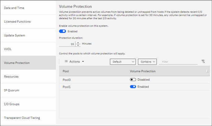
Figure 5-25 Volume Protection
5.13.2 Volume resizing
Fully allocated and thin-provisioned volumes can have their sizes increased or decreased. A volume can be expanded with concurrent I/Os for some operating systems. However, never attempt to shrink a volume that is in use that contains data because volume capacity is removed from the end of the disk, whether that capacity is in use by a server. A volume cannot be expanded or shrunk during its quick initialization process.
Expanding a volume
You can expand volumes for the following reasons:
•To increase the available capacity on a specific volume that is mapped to a host.
•To increase the size of a volume to make it match the size of the source or master volume so that it can be used in a FlashCopy mapping or Metro Mirror relationship.
Figure 5-26 shows the Expand Volume window.
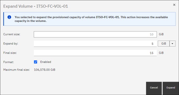
Figure 5-26 Expand Volumes
Shrinking a volume
Volumes can be reduced in size if necessary. If a volume does not contain any data, it is unlikely that you encounter any issues when shrinking its size. However, if a volume is in use and contains data, do not shrink its size because IBM Spectrum Virtualize is unaware if it is removing used or non-used capacity.
|
Attention: When you shrink a volume, capacity is removed from the end of the disk, whether that capacity is in use. Even if a volume includes free capacity, do not assume that only unused capacity is removed when you shrink a volume.
|
Figure 5-27 shows shrinking volumes.

Figure 5-27 Shrink volumes
..................Content has been hidden....................
You can't read the all page of ebook, please click here login for view all page.