

IBM i considerations
The IBM Spectrum Virtualize family of block storage systems including the IBM Flash System 5000 series, IBM FlashSystem 7200, and IBM FlashSystem 9200/9200R provides a broad range of flexible and scalable SAN storage solutions. These solutions can meet demands of IBM i customers for entry to high-end storage infrastructure solutions.
All family members that are based on IBM Spectrum Virtualize software use a common management interface. They also provide a comprehensive set of advanced functions and technologies, such as advanced Copy Services functions, encryption, compression, storage tiering, NVMe flash, and storage class memory (SCM) devices, and external storage virtualization. Many of these advanced functions and technologies also are of interest to IBM i customers who are looking for a flexible, high-performing, and highly available SAN storage solution.
This appendix provides important considerations and guidelines for successfully implementing the IBM Spectrum Virtualize family and its advanced functions with IBM i. Unless otherwise stated, the considerations also apply to previous generations of products like the IBM Storwize family, the IBM Flash System 9100 series, and IBM Flash System V9000.
This appendix includes the following topics:
IBM i Storage management
Because of the unique IBM i storage architecture, special considerations for planning and implementing a SAN storage solution are required (also with IBM Spectrum Virtualize-based storage). This section describes how IBM i storage management manages its available disk storage.
Many host systems require the user to take responsibility for how information is stored and retrieved from the disk units. An administrator must also manage the environment to balance disk usage, enable disk protection, and maintain balanced data to be spread for optimum performance.
The IBM i architecture is different in a way that the system takes over many of the storage management functions, which on other platforms are the responsibility of a system administrator.
IBM i, with its Technology Independent Machine Interface (TIMI), largely abstracts the underlying hardware layer from the IBM i operating system and its users and manages its system and user data in IBM i disk pools, which are also called auxiliary storage pools (ASPs).
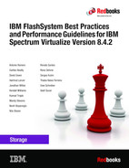
When you create a file, you do not assign it to a storage location. Instead, the IBM i system places the file in the location that ensures the best performance from an IBM i perspective (see Figure A-1).
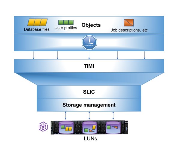
Figure A-1 IBM i storage management spreads objects across LUNs
|
Note: When a program presents instructions to the machine interface for execution, the interface appears to the program as the system hardware, but it is not. The instructions that are presented to TIMI pass through a layer of microcode before they are understood by the hardware.
|
As a component of the IBM i System Licensed Internal Code (SLIC), IBM i storage management normally spreads the data in the file across multiple disk units (LUNs when external storage is used). When you add records to the file, the system automatically assigns more space on one or more disk units or LUNs.
Single-level storage
IBM i uses a single-level storage, object-orientated architecture. It sees all disk space and the main memory or main storage as one address space. It also uses the same set of virtual addresses to cover main memory and disk space. Paging the objects in this virtual address space is performed in 4 KB pages, as shown in Figure A-2. After a page gets written to disk, it is stored with metadata, including its unique virtual address. For this purpose, IBM i originally used a proprietary 520 bytes per sector disk format.
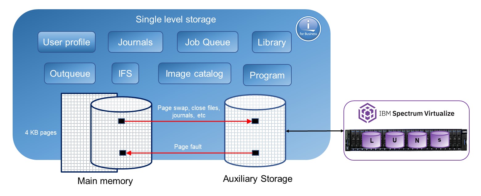
Figure A-2 Virtual address space.
|
Note: The system storage that is conformed with main storage or main memory and auxiliary storage is addressed in the same way. This single, device-independent addressing mechanism means that objects are referred to by name or name and library, but never by disk location. The virtual addressing of IBM i is independent of the physical location of the object, type, capacity, and the number of disks units or LUNs on the system.
|
The IBM i disk storage space is managed by using auxiliary storage pools. Each IBM i system has a system ASP (ASP 1), which includes the load source (also known as boot volume on other systems) as disk unit 1, and optional user ASPs (ASP 2-33). The system ASP and the user ASPs are designated as SYSBAS and constitute the system database.
The single-level storage with its unique virtual addresses also implies that the disk storage that is configured in SYSBAS of an IBM i system must be available in its entirety for the system to remain operational. It cannot be shared for simultaneous access by other IBM i systems.
To allow for sharing of IBM i disk storage space between multiple IBM i systems in a cluster, switchable independent auxiliary storage pools (IASPs) can be configured. The IBM i auxiliary storage pools architecture is shown in Figure A-3.
Figure A-3 IBM i auxiliary storage pools architecture
Single-level storage makes main memory work as a large cache. Reads are done from pages in main memory, and requests to disk are done only when the needed page is not there yet.
Writes are done to main memory or main storage, and write operations to disk are performed as a result of swap, file close, or forced write. Application response time depends on disk response time and many other factors.
Other storage-related factors include the IBM i storage pool configuration for the application, how frequently the application closes files, and whether it uses journaling. An example is shown in Figure A-4.
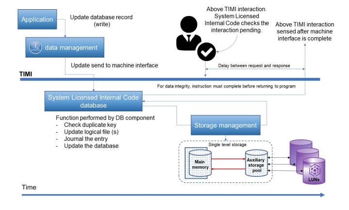
Figure A-4 TIMI atomicity
IBM i response time
IBM i customers often are concerned about the following types of performance:
•Application response time: The response time of an application transaction. This time is usually critical for the customer.
•Duration of batch job: Batch jobs are usually run during the night or other off-peak periods. The duration of a batch job is critical for the customer because it must be finished before regular daily transactions start.
•Disk response time: Disk response time is the time that is needed for a disk I/O operation to complete. It includes the service time for I/O processing and the wait time for potential I/O queuing on the IBM i host.
Disk response time can significantly influence application response time and the duration of a batch job. Because the performance of the disk subsystem has a significant effect on overall system performance, this issue is discussed next.
Disk performance considerations
Performance of the disk subsystem significantly affects overall IBM i system performance. especially in a commercial data processing environment in which a large volume of data must proceed. Disk drives or LUNs’ response times contribute to a major portion of the overall response time (OLTP) or runtime (batch).
The performance of a disk subsystem is affected by the type of protection (RAID, DRAID, or mirroring).
The amount of free space (GB) on the drives and the extent of fragmentation also has an effect. The reason for the effect is the need to find suitable contiguous space on the disks to create objects or extend objects. Disk space often is allocated in extents of 32 KB. If a 32 KB contiguous extent is not available, two extents of 16 KB are used.
Next, we discuss the following important disk performance considerations:
•Disk I/O requests
•Disk subsystems
•Disk operation
•Asynchronous I/O wait
•Disk protection
•Logical Database I/O versus physical disk I/O
Disk I/O requests
Greater sources of disk request are faults that arise from a request for information not being satisfied by what is in memory. Request to bring information in to memory also result in disk I/O. Memory pages also can be purged from periodically, which results disk I/O activity.
|
Note: The Set Object Access (SETOBJACC) command on IBM i temporarily changes the speed of access to an object by bringing the object into a main storage pool or purging it from all main storage pools. An object can be kept in main storage resident by selecting a pool for the object that has available space and does not have jobs that are associated with it.
For more information see, this IBM Documentation web page.
|
Disk subsystems
Typically, an external disk subsystem (storage system) connects a server through a SAN, as shown in Figure .
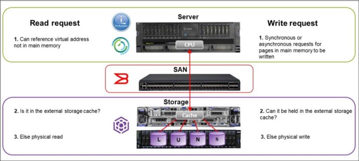
Figure A-5 Disk subsystem
A request information (data or instructions) from the CPU based on user interactions are submitted to the disk subsystem if it cannot be satisfied from the contents of memory. Whether the request can be satisfied from the disk subsystem cache, it responds or forwards the request to the disk drives or LUNs.
Similarly, a write request is retained in memory, unless the operating system determines that it must be written to the disk subsystem. The operating system attempts to satisfy the request by writing to the controller cache.
|
Note: The QAPMDISKRB from collections services data files in IBM i includes disk file response bucket entries. It also contains one record for each device resource name. It is intended to be used with the QAPMDISK file. For more information, see this IBM Documentation web page.
|
Disk operation
On IBM i, physical disk I/O requests are categorized as database (physical or logical files) or nondatabase I/Os, as shown in Figure A-6.
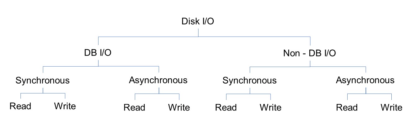
Figure A-6 Disk I/O on IBM i
The time that is taken to respond to synchronous disk I/Os contributes to the Online transaction processing (OLTP) response time or batch runtime. With asynchronous I/O, the progress of a request does not wait for the completion of I/O.
Often, write requests are asynchronous, including journal deposits with commitment control. However, the writes become synchronous if journaling is active without commitment control.
Asynchronous I/O wait
On IBM i, at times jobs might have to wait for asynchronous I/O requests to complete. The job issues a request but requires the data sooner than it can be made available by the disk subsystem. When a job waits for asynchronous I/O portion of the operation, it becomes synchronous. The time is recorded as asynchronous disk I/O wait in the QAPMJOBL file.
JBWIO is the number of times that the process specifically waited for outstanding asynchronous I/O operations to complete. For more information, see this IBM Documentation web page.
This issue might be caused by faster processors running with relatively poor disk subsystems performance. Disk subsystem performance can be affected by busy or slow disk, small I/O cache.
Disk protection
For more information about external storage consideration to set up your RAID protection, see Chapter 3, “Planning, configuring, and managing storage backend” on page 69.
|
Note: If you need high I/O performance on your IBM i workload, you can create a DRAID 1 on your supported storage system, such as IBM Flash System 7200 and 9200 with IBM Spectrum Virtualize 8.4. In this configuration, the rebuild area is distributed over all member drives. The minimum extent size for this type of DRAID is 1024 MB.
|
Logical database I/O versus physical disk I/O
Information that is in partition buffers memory is available for use by any job or thread. Commonly, information is available in the partition buffer as a block of data rather than individual records. Data in a job buffer is available for use by the job only.
When an application program requests data, storage management checks whether they are available in memory. If so, it is moved to the open data path in the job buffer. If the data is not in memory, the request is submitted to the disk subsystem as a read command.
In that context, logical Database I/O information is moved between the open data path of user program and the partition buffer. This information is a count of the number of buffer movements and not a reflection of the records that were processed.
For more information, see the following IBM Documentation web pages:
Physical disk I/O occurs when information is read or written as a block of data to or from the disk. It involves the movement of data between the disk and the partition buffer in memory. For more information, see this IBM Documentation web page.
Planning for IBM i storage capacity
To correctly plan the storage capacity that is provided by IBM Spectrum Virtualize family systems for IBM i, you must be aware of IBM i block translation for external storage that is formatted in 512-byte blocks. IBM i internal disks use a block size of 520 or 4160 bytes.
Because IBM Spectrum Virtualize storage for hosts is formatted with 512-byte blocks, a translation or mapping is required to attach it to IBM i. IBM i changes the data layout to support 512-byte blocks (sectors) in external storage by using an extra ninth sector to store the headers for every page.
The eight 8-byte headers from each 520-byte sector of a page are stored in the ninth sector, which is different than 520-byte sector storage where the 8 bytes are stored continuously with the 512 bytes of data to form the 520-byte sector.
The data that was stored in eight sectors is now stored by using nine sectors; therefore, the required disk capacity on IBM Spectrum Virtualize based systems is 9/8 of the IBM i usable capacity. Similarly, the usable capacity in IBM i is 8/9 of the allocated capacity in these storage systems.
When attaching IBM Spectrum Virtualize family storage to IBM i, plan for the extra capacity on the storage system so that the 8/9ths of the effective storage capacity that is available to IBM i covers the capacity requirements for the IBM i workload.
The performance effect of block translation in IBM i is small or negligible.
Figure A-7 shows byte sectors for IBM i.
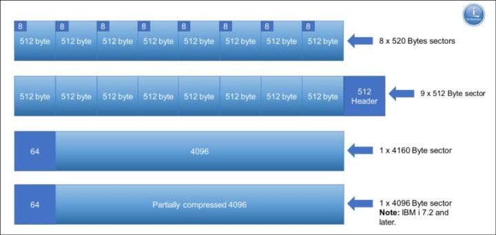
Figure A-7 IBM i with different sector sizes
Storage connection to IBM i
IBM Spectrum Virtualize storage can be attached to IBM i in the following ways:
•Native connection without the use of the IBM PowerVM Virtual I/O Server (VIOS)
•Connection with VIOS in:
– NPIV mode
– Virtual SCSI mode
The decision for IBM i native storage attachment or a VIOS attachment is based on the customer’s requirements. Native attachment has its strength in terms of simplicity and can be a preferred option for static and smaller IBM i environments with only a few partitions. It does not require extra administration and configuration of a VIOS environment. However, it also provides the least flexibility and cannot be used with IBM PowerVM advanced functions, such as Live Partition Mobility or remote restart.
Table A-1 lists key criteria to help you with the decision for selecting an IBM i storage attachment method.
Table A-1 Comparing IBM i native and Virtual I/O Server attachment
|
Criteria
|
Native attachment
|
VIOS attachment
|
|
Simplicity
(Configuration, maintenance, failure analysis) |
ü
|
More complex
|
|
Performance
|
ü
|
ü
(with NPIV)
|
|
Consolidation
(Storage or network adapters) |
More limited
|
ü
|
|
PowerVM advanced functions
(Partition mobility, suspend, or resume, remote restart, private cloud deployment) |
Not available
|
ü
|
|
Hardware support
(storage or network adapters, entry level servers) |
More limited
|
ü
|
Next, we discuss the guidelines and preferred practices for each type of connection.
|
Note: For more information about the current requirements, see the following web pages:
|
Native attachment
Native connection support for IBM i with IBM Spectrum Virtualize storage is available with IBM Power Systems POWER7 or later server technology. It requires IBM i 7.1, Technology Refresh (TR) 7 or later for POWER7, and IBM i 7.1 TR 8 or later for POWER8.
Native connection with SAN switches can be done by using the following adapters:
•32 Gb PCIe3 2-port FC adapters feature number #EN1A or #EN1B (IBM POWER9™ only)
•16 Gb PCIe3 4-port FC adapters feature number #EN1C or #EN1D (POWER9 only)
•16 Gb PCIe3 2-port FC adapters feature number #EN0A or #EN0B
•8 Gb PCIe 2-port FC adapters feature number #5735 or #5273
•4 Gb PCIe 2-port Fibre Channel (FC) adapters feature number #5774 or #5276
Direct native connection without SAN switches can be done by using the following adapters:
•16 Gb adapters in IBM i connected to 16 Gb adapters in IBM Spectrum Virtualize V7.5 or later based storage with non-NPIV target ports
•4 Gb FC adapters in IBM i connected to 8 Gb adapters in IBM Spectrum Virtualize based storage with non-NPIV target ports
For resiliency and performance reasons, connect IBM Spectrum Virtualize storage to IBM i with multipath by using two or more FC adapters. Consider the following points:
•You can define a maximum of 127 LUNs (up to 127 active + 127 passive paths) to a 16 or 32 Gb port in IBM i, with IBM i 7.2 Technology Refresh (TR) 7 or later, and with IBM i 7.3 TR3 or later.
•You can define a maximum of 64 LUNs (up to 64 active + 64 passive paths) to a
16 or 32 Gb port with IBM i release and TR lower than i 7.2 TR7 and i 7.3 TR3.
16 or 32 Gb port with IBM i release and TR lower than i 7.2 TR7 and i 7.3 TR3.
•You can define a maximum of 64 LUNs (up to 64 active + 64 passive paths) to a 4 or 8 Gb port, regardless of the IBM i level.
The LUNs report in IBM i as disk units with type 2145.
IBM i enables SCSI command tag queuing in the LUNs from natively connected IBM Spectrum Virtualize storage. The IBM i queue depth per LUN and path with this type of connection is 16.
VIOS attachment
The following FC adapters are supported for VIOS attachment of IBM i to IBM Spectrum Virtualize storage:
•32 Gb PCIe3 2-port FC adapter feature number #EN1A or #EN1B (POWER9 only)
•16 Gb PCIe3 4-port FC adapter feature number #EN1C or #EN1D (POWER9 only)
•16 Gb PCIe3 2-port FC adapter feature number #EN0A or #EN0B
•8 Gb PCIe 2-port FC adapter feature number #5735 or #5273
•8 Gb PCIe2 2-port FC adapter feature number #EN0G or #EN0F
•8 Gb PCIe2 4-port FC adapter feature number #5729
•8 Gb PCIe2 4-port FC adapter feature number #EN12 or #EN0Y
|
Important: For more information about the current requirements, see the following web pages:
|
Connection with VIOS NPIV
IBM i storage attachment support that uses IBM PowerVM® Virtual I/O Server N_Port ID Virtualization (NPIV) was introduced with POWER6 server technology. With NPIV, volumes (LUNs) from the IBM Spectrum Virtualize storage system are directly mapped to the IBM i server. VIOS does not see NPIV connected LUNs; instead, it is an FC pass-through.
The storage LUNs are presented to IBM i with their native device type of 2145 for IBM Spectrum Virtualize-based storage. NPIV attachment requires 8 Gb or newer generation FC adapter technology and SAN switches that must be NPIV enabled, as shown in Figure A-8.
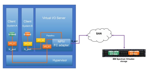
Figure A-8 IBM i SAN access using NPIV
Redundant VIOS with NPIV
For resiliency and performance reasons, connect IBM Spectrum Virtualize storage to IBM i by using multipathing across two or more VIOS servers.
Observe the following rules for mapping IBM i server virtual FC client adapters to the physical FC ports in VIOS when implementing NPIV connection:
•You can map up to 64 virtual FC adapters to the same physical FC adapter port in VIOS. With VIOS 3.1 and later, this limit was increased for support of mapping of up to 255 virtual FC adapters to a 32 Gb physical FC adapter port.
•Mapping of more than one NPIV client virtual FC adapter from the same IBM i system to a VIOS physical FC adapter port is supported since IBM i 7.2 TR7 and i 7.3 TR3; however, when PowerVM partition mobility is used, only a single virtual FC adapter can be mapped from the same IBM i system to a VIOS physical FC adapter port.
•You can use the same port in VIOS for NPIV mapping and connecting with VIOS virtual SCSI (VSCSI).
•If PowerHA solutions with IBM i independent auxiliary storage pools (IASPs) are implemented, you must use different virtual FC adapters for attaching the IASP LUNs, and not share adapters between SYSBAS and IASP LUNs.
You can configure a maximum of 127 LUNs (up to 127 active + 127 passive paths) to a virtual FC adapter with IBM i 7.2 TR7 or later, and with IBM i 7.3 TR3 or later.
You can configure a maximum of 64 LUNs (up to 64 active + 64 passive paths) to a virtual FC adapter with IBM i release and TR lower than i 7.2 TR7 and i 7.3 TR3.
IBM i enables SCSI command tag queuing for LUNs from VIOS NPIV connected to IBM Spectrum Virtualize storage. The IBM i queue depth per LUN and path with this type of connection is 16.
|
Note: If you encounter issues with NPIV/Virtual FC of IBM i that is attached to an IBM Spectrum Virtualize, such as missing paths and missing disk units, consider the following suggestions:
•Use System Snapshot (SYSSNAP) and be sure to include LIC LOGs, QHST, and PALs. Change the date range to include the date range of the problem. For more information, see this IBM Support web page.
•VIOS SNAPs can be collected from the VIOS partitions as part of the SYSSNAP or separately. For more information, see this IBM Support web page.
•Collect switch logs as close as possible to the time of the problem.
•Collect the applicable statesave, snap, and so on, from the IBM Spectrum Virtualize at the time the problem is occurring. This information is needed by the IBM Storage Support team.
If you experience a performance problem with poor disk response time and the IBM Spectrum Virtualize is connected with NPIV, see this IBM Support web page.
|
NPIV acceleration
Virtual I/O Server version 3.1.2 or later strengthened FC N_Port ID Virtualization (NPIV) to provide multi-queue support. This enhanced performance, including more throughput, reduced latency, and higher IOPS, spreads the I/O workload across multiple work queues.
The following FC adapter feature codes are supported:
•32 Gb PCIe3 2-port FC adapters feature number #EN1A or #EN1B (POWER9 only)
•16 Gb PCIe3 4-port FC adapters feature number #EN1C or #EN1D (POWER9 only)
•16 Gb PCIe3 2-port FC adapters feature number #EN2A or #EN2B
|
Note: NPIV acceleration is supported by IBM i 7.2 or later, and by the firmware level for IBM Power Systems 9 is FW940 or later.
|
Connection with VIOS virtual SCSI
IBM i storage attachment by way of the IBM PowerVM Virtual I/O Server Connection that uses virtual SCSI was introduced with IBM Power Systems POWER6 technology.
When deciding on an IBM PowerVM Virtual I/O Server storage attachment for IBM i, NPIV attachment is often preferred over virtual SCSI attachment for the following reasons:
•With virtual SCSI, an emulation of generic SCSI devices is performed by VIOS for its client partitions, such as IBM i, which requires extra processing and adds a small delay to I/O response times.
•Virtual SCSI provides much lower scalability in terms of maximum supported LUNs per virtual adapter than NPIV, and requires more storage management, such as multipath configuration and customization at the VIOS layer, which adds complexity.
•Because of the virtual SCSI emulation unique device characteristics of the storage device, such as device type or in case of tape devices media type and other device attributes are no longer presented to the IBM i client.
Virtual SCSI attachment is not supported for PowerHA LUN level switching technology, which is required for IASP HyperSwap solutions with IBM Spectrum Virtualize. Similar considerations for NPIV apply with regard to the use of IBM i multipathing across two or more VIOS to improve resiliency and performance. However, because multipathing is implemented at the VIOS layer with virtual SCSI, the following considerations apply:
•IBM i multipathing is performed with two or more VSCSI client adapters, each of them assigned to a VSCSI server adapter in different VIOS. With virtual SCSI, volumes (LUNs) from the IBM Spectrum Virtualize storage system are not mapped directly to an IBM i host but instead to the two or more VIOS servers. These LUNs are detected as hdisks on each VIOS and must be mapped as a virtual target device to the relevant VSCSI server adapters to be used by the IBM i client.
•In addition to IBM i multipathing across multiple VIOS servers, with virtual SCSI, multipathing must be implemented at the VIOS server layer to provide further I/O parallelism and resiliency by using multiple physical FC adapters and SAN fabric paths from each VIOS server to its storage.
The IBM recommended multipath driver for IBM Spectrum Virtualize based storage running microcode V7.6.1 or later is the VIOS built-in AIXPCM multipath driver, which replaces the previously recommended SDDPCM multipath driver.
For more information, see this IBM Support web page.
IBM i storage attachment by using the IBM PowerVM Virtual I/O Server Connection that uses virtual SCSI was introduced with IBM Power Systems POWER6 technology.
When deciding on an IBM PowerVM Virtual I/O Server storage attachment for IBM i, NPIV attachment is often preferred over virtual SCSI attachment for the following reasons:
•With virtual SCSI, an emulation of generic SCSI devices is performed by VIOS for its client partitions, such as IBM i, which requires extra processing and adds a small delay to I/O response times.
•Virtual SCSI provides much lower scalability in terms of the maximum supported LUNs per virtual adapter than NPIV. It also requires more storage management, such as multipath configuration and customization at the VIOS layer, which adds complexity.
•Because of the virtual SCSI emulation unique device characteristics of the storage device, such as device type (or in the case of tape devices), media type and other device attributes are no longer presented to the IBM i client.
•Virtual SCSI attachment is not supported for PowerHA LUN level switching technology, which is required for IASP HyperSwap solutions with IBM Spectrum Virtualize.
Similar considerations for NPIV apply with regard to the use of IBM i multipathing across two or more VIOS to improve resiliency and performance. However, because multipathing is also implemented at the VIOS layer with virtual SCSI, the following considerations apply:
•IBM i multipathing is performed with two or more VSCSI client adapters, each is assigned to a VSCSI server adapter in different VIOS. With virtual SCSI, volumes (LUNs) from the IBM Spectrum Virtualize storage system are not mapped directly to an IBM i host but to the two or more VIOS servers. These LUNs that are detected as HDDs on each VIOS must be mapped as a virtual target device to the relevant VSCSI server adapters to be used by the IBM i client.
•In addition to IBM i multipathing across multiple VIOS servers, with virtual SCSI, multipathing is implemented at the VIOS server layer to provide further I/O parallelism and resiliency by using multiple physical FC adapters and SAN fabric paths from each VIOS server to its storage.
•The IBM recommended multipath driver for IBM Spectrum Virtualize-based storage running microcode V7.6.1 or later is the VIOS built-in AIXPCM multipath driver, which replaces the previously recommended SDDPCM multipath driver.
•For more information, see this IBM Support web page.
Up to 4095 LUNs can be connected per target, and up to 510 targets per port in a physical adapter in VIOS. With IBM i 7.2 and later, you can attach a maximum of 32 disk LUNs to a virtual SCSI adapter in IBM i. With IBM i releases before i 7.2, a maximum of 16 disk LUNs can be attached to a virtual SCSI adapter in IBM i. The LUNs are reported in IBM i as generic SCSI disk units of type 6B22.
IBM i enables SCSI command tag queuing in the LUNs from VIOS VSCSI connected to IBM Spectrum Virtualize storage. The queue depth on a LUN with this type of connection is 32.
Setting attributes in VIOS
This section describes the values of specific device attributes in VIOS that must be configured for resiliency and performance.
FC adapter attributes
With VIOS virtual SCSI connection or NPIV connection, use the VIOS chdev command to specify the following attributes for each SCSI I/O Controller Protocol Device (fscsi) device that connects an IBM Spectrum Virtualize storage LUN for IBM i:
•The attribute fc_err_recov must be set to fast_fail
•The attribute dyntrk must be set to yes
The specified values for the two attributes specify how the VIOS FC adapter driver or VIOS disk driver handle specific types of fabric-related failures and dynamic configuration changes. Without setting these values for the two attributes, the way these events are handled is different and causes unnecessary retries or manual actions.
|
Note: These attributes also are set to the recommended values when applying the default rules set that is available with VIOS 2.2.4.x or later.
|
Disk device attributes
With VIOS virtual SCSI connection, use the VIOS chdev command to specify the following attributes for each hdisk device that represents an IBM Spectrum Virtualize storage LUN connected to IBM i:
•If IBM i multipathing across two or more VIOS servers is used, the attribute reserve_policy must set to no_reserve.
•The attribute queue_depth must be set to 32.
•The attribute algorithm must be set to shortest_queue.
Setting reserve_policy to no_reserve is required to be set in each VIOS if multipath with two or more VIOS is implemented to prevent SCSI reservations on the hdisk device.
Set queue_depth to 32 for performance reasons. Setting this value ensures that the maximum number of I/O requests that can be outstanding on an HDD in the VIOS at a time matches the maximum number of 32 I/O operations that IBM i operating system allows at a time to one VIOS VSCSI-connected LUN.
Set algorithm to shortest_queue for performance reasons. Setting this value allows the AIXPCM driver in VIOS to use a dynamic load balancing instead of the default path failover algorithm for distributing the I/O across the available paths to IBM Spectrum Virtualize storage.
Setting a physical volume identifier (PVID) for HHD devices that are used for virtual SCSI attachment of IBM i client partitions is not recommended because it makes those devices ineligible for a possible later migration to NPIV or native attachment.
|
Important: While working with SCSI and NPIV, you cannot mix both regarding the paths to the same LUN. However, VIOS supports NPIV and SCSI concomitantly; that is, some LUNs can be attached to the virtual WWPNs of the NPIV FC adapter. At the same time, the VIOS also can provide access to LUNs that are mapped to virtual target devices and exported as VSCSI devices.
You can have one or more Virtual I/O Servers providing the pass-through function for NPIV. Also, you can have one or more Virtual I/O Servers hosting VSCSI storage. Therefore, the physical HBA in the Virtual I/O Server supports NPIV and VSCSI traffic.
|
Guidelines for Virtual I/O Server resources
Be aware of the memory requirements of the hypervisor when determining the overall memory of the system. Above and beyond the wanted memory for each partition, you must add memory for virtual resources (VSCSI and Virtual FC) and hardware page tables to support the maximum memory value for each partition.
The suggestion is to use the IBM Workload Estimator tool to estimate the needed Virtual I/O Server resources. However, as a starting point in context of CPU and memory for Virtual I/O Server. For more information, see this IBM Support web page.
Disk drives for IBM i
This section describes how to implement internal disk drives in IBM Spectrum Virtualize storage or externally virtualized back-end storage for an IBM i host. These suggestions are based on the characteristics of a typical IBM i workload, such as a relatively high write ratio, a relatively high access density, and a small degree of I/O skew because of the spreading of data by IBM i storage management.
Considering these characteristics and typical IBM i customer expectations for low I/O response times, we expect that many SAN storage configurations for IBM i are based on an all-flash storage configuration.
If a multitier storage configuration that uses enterprise class (tier0_flash) and high-capacity (tier1_flash) flash drives or even enterprise hard disk drives (tier2_HDD) is preferred for less demanding workloads or for commercial reasons, ensure that a sufficiently large part of disk capacity is on flash drives. As a best practice for a multitier configuration considering the typically low IBM i I/O skew, at least 20% of IBM i capacity should be based on the higher tier flash storage technology.
Even if specific parts of IBM i capacity are on flash drives, it is important that you provide enough HDDs with high rotation speed for a hybrid configuration with flash drives and HDDs. Preferably, use 15 K RPM HDDs of 300 GB or 600 GB capacity, along with flash technology.
IBM i transaction workload usually achieves the best performance when disk capacity is used entirely from enterprise class flash (tier0_flash) storage. High capacity or read-intensive flash drives are typically not the best choice for IBM i performance critical workload. This issue is especially for the top storage tier, considering a usually high IBM i write percentage of often 50% and higher, the disk write amplification by using RAID 6, and the significant lower random write performance of tier1 compared to tier0 flash drives.
The use of a multitier storage configuration by IBM Spectrum Virtualize storage is achieved by using Easy Tier. For more information, see Implementing the IBM SAN Volume Controller with IBM Spectrum Virtualize Version 8.4.2, SG24-8507.
Even if you do not plan to install multitier storage configuration, or have no multitier storage configuration that is installed, you can still use Easy Tier for intra-tier rebalancing. You also can evaluate your workload with its I/O skew, which provides information about the benefit you might gain by adding flash technology in the future.
Compression considerations
If compression is wanted, the preferred choice for using compression at the IBM Spectrum Virtualize storage system layer for performance critical IBM i workload is by using IBM FlashCore module (FCM) hardware compression technology at the disk drive level within IBM Spectrum Virtualize standard pools or data reduction pools (DRPs) with fully allocated volumes. These configuration options do not affect performance compared to other compression technologies, such as DRP compressed volumes or Real-Time Compression at the storage subsystem level.
|
Important: Data reduction or deduplication can be used with IBM i, which affects performance positively.
Nevertheless, the performance is affected and different whenever something is touched, such as 30 minutes taking 3 - 18 hours. The data is affected whenever something is created, changed, or used. The integrity of the objects is maintained.
However, if a physical page on disk is corrupted, potentially hundreds or thousands of objects become corrupted instead of only one. Another consideration is the amount of wear that occurs on the drives from so much read/write activity.
If you plan to use deduplication for archival or test purposes, deduplication might be a viable solution for saving huge amounts of storage. If the deduplication solution is planned for a production or development environment, we strongly recommend that you test thoroughly before committing.
|
Storage sizing and performance modeling
IBM provides tools, such as IBM Storage Modeller (StorM) and IntelliMagic Disk Magic for IBM representatives and Business Partners, which are recommended to be used for performance modeling and sizing before implementing a wanted IBM Spectrum Virtualize storage configuration for IBM i. These tools allow the user to enter the performance data of the current IBM i workload manually or by using file import from IBM i (5770-PT1 reports or PDI data) or from IBM Spectrum Control performance data. Enter the current storage configuration and model the wanted configuration.
When modeling Easy Tier, specify the lowest skew level for IBM i workload or import an existing I/O skew curve from available Easy Tier reports. The steps that are taken for sizing and modeling IBM i are shown in Figure A-9.
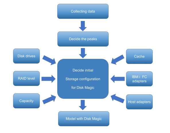
Figure A-9 Diagram of sizing and modeling for IBM i using Disk Magic
The modeling helps assure an adequate solution sizing by providing predictions for the modeled IBM Spectrum Virtualize storage resource of system usage, predicted disk response time for IBM i, and usage and response times at workload growth.
|
Note: Contact your IBM representative or IBM Business Partner to discuss a performance modeling and sizing for a planned IBM Spectrum Virtualize storage solution for IBM i.
|
IBM i Unmap support
To better use IBM Spectrum Virtualize storage flash technology with an efficient storage space allocation and deallocation, IBM i supports the space of storage system unmap capabilities by corresponding host unmap functions.
Initially, IBM i unmap support that is implemented by way of the SCSI Write Same command was introduced with i 7.2 TR8 and i 7.3 TR4 for LUN initialization only; that is, for the add disk units to ASP function.
With i 7.3 TR9 and i 7.3 TR5, runtime support was added, which also supports synchronous unmap for scenarios, such as object deletion and journal clearance. The runtime unmap algorithm was further enhanced supported by i 7.3 TR7 and i 7.4 TR1, which implements an asynchronous periodic free-space cleaning.
IBM Spectrum Virtualize V8.1.1 and later storage systems can use the unmap function for efficiently deallocate space, such as for volume deletion, on their back-end storage by sending SCSI unmap commands to specific supported internal SSDs and FCMs, and selected virtualized external flash storage.
Space reclamation that is triggered by host unmap commands is supported by IBM Spectrum Virtualize V8.1.2 and later for DRP thin provisioned volumes, which can increase the free capacity in the storage pool so that it becomes available also for use by other volumes in the pool.
For more information about IBM Spectrum Virtualize storage SCSI unmap support, see 4.1.2, “Data reduction pools” on page 117, and this IBM Support web page.
Defining LUNs for IBM i
LUNs for an IBM i host are defined from IBM Spectrum Virtualize block-based storage. They are created from available extents within a storage pool, the same way as for open system hosts.
Even though IBM i supports a usable LUN size of up to 2 TB (1 byte for IBM Spectrum Virtualize storage), the use of only a few large-size LUNs for IBM i is not recommended for performance reasons.
In general, the more LUNs that are available to IBM i, the better the performance for the following the reasons:
•If more LUNs are attached to IBM i, storage management uses more threads and therefore enables better performance.
•More LUNs provide a higher I/O concurrency, which reduces the likelihood of I/O queuing and therefore the wait time component of the disk response time, which results in lower latency of disk I/O operations.
For planning, consider that a higher number of LUNs might also require more physical or virtual FC adapters on IBM i based on the maximum number of LUNs that is supported by IBM i per FC adapter port.
The sizing process helps to determine a reasonable number of LUNs that are required to access the needed capacity, while meeting performance objectives. Regarding both of these aspects and the preferred practices, consider the following guidelines:
•For any IBM i disk pool (ASP), define all the LUNs as the same size.
•40 GB is the preferred minimum LUN size.
•You should not define LUNs larger than approximately 200 GB.
|
Note: This rule is not a fixed rule because it is important that enough LUNs are configured, with which this guideline helps. Selecting a larger LUN size should not lead to configurations, such as storage migrations, with a significantly fewer number of LUNs being configured with possibly detrimental effects on performance.
|
•A minimum of 8 LUNs for each ASP is preferred for small IBM i partitions and typically a couple of dozen LUNs for medium and up to a few hundreds for large systems.
When defining LUNs for IBM i, consider the following required minimum capacities for the load source (boot disk) LUN:
•With IBM i release 7.1, the minimum capacity is 20 GB
•With IBM i release 7.2 before TR1, the minimum capacity is 80 GB in IBM i
•With IBM i release 7.2 TR1 and later, the minimum capacity is 40 GB in IBM i
IBM Spectrum Virtualize dynamic volume expansion is supported for IBM i with IBM i 7.3 TR4 and later. An IBM i IPL is required to use the extra volume capacity.
|
Tip: For more information about cross-referencing IBM i disks units with IBM Spectrum Virtualize LUNs by using N-Port ID Virtualization (NPIV), see this IBM Support web page.
|
Disk arms and maximum LUN size
Selected limits that are related to disk arms and LUNs sizes were increased in IBM i 7.4, as listed in Table A-2.
Table A-2 Limits increased for Max Disk Arms and LUN size
|
System Limits
|
IBM i 7.2
|
IBM i 7.3
|
IBM i 7.4
|
|
Disk arms in all basic auxiliary storage pools (ASPs 1 - 32), per LPAR
|
2047
|
2047
|
3999
|
|
Disk arms in all independent auxiliary storage pools (IASPs 33 - 255) in all nodes in a cluster
|
2047
|
2047
|
5999
|
|
Maximum combined number of disk arms and redundant connections to disk units
|
35.600
|
35.600
|
35.600
|
|
512 byte block size LUNs a
|
2 TB
|
2 TB
|
2 TB
|
|
4096 byte block size LUNs b
|
2 TB
|
2 TB
|
16 TB
|
a. Actual limit is one block short of the maximum that is shown in Table A-2. For all 512-block LUNs, the maximum is still up to 2 TB, including IBM Storwize LUNs and SAN Volume Controller LUNs.
b. Includes IBM FlashSystems LUNs, and 4 K block SAS disks (VSCSI attached).
|
Note: For more information about these limits, and others, see IBM Documentation web page.
|
Data layout
Spreading workloads across all IBM Spectrum Virtualize storage components maximizes the use of the hardware resources in the storage subsystem. I/O activity must be balanced between the two nodes or controllers of the IBM Spectrum Virtualize storage system I/O group, which is usually taken care of by the alternating preferred node volume assignments at LUN creation.
However, especially with improper sizing or unanticipated workload increases, performance problems might arise when sharing resources because of resource contention. Some isolation of workloads, at least regarding a shared back-end storage, can be accomplished by a configuration in which each IBM i ASP or LPAR has its own managed storage pool.
Such a configuration with dedicated storage pools results in a trade-off between accomplishing savings from storage consolidation and isolating workloads for performance protection. This is because a dedicated storage pool configuration likely requires more back-end storage hardware resources because it cannot use the averaging effect of multiple workloads that typically show their peaks at different intervals.
Consider the following data layout:
•For all-flash storage configurations (assuming a correctly sized storage backend), no reason often exists for not sharing the disk pool among multiple IBM i workloads.
•For hybrid configurations with Easy Tier on mixed HDD and flash disks, the storage pool can also be shared among IBM i workloads. Only very large performance critical workloads must be configured in isolated disk pools.
•For HDD-only pools, ensure that you isolate performance critical IBM i workloads in separate storage pools.
•Avoid mixing IBM i LUNs and non-IBM i LUNs in the same disk pool.
Apart from the use of Easy Tier on IBM Spectrum Virtualize for managing a multitier storage pool, an option also exists to create a separate storage pool for different storage tiers on IBM Spectrum Virtualize storage and create different IBM i ASPs for each tier. IBM i applications that have their data in an ASP of a higher storage tier experience a performance boost compared to those applications that use an ASP with a lower storage tier.
IBM i internal data relocation methods, such as the ASP balancer hierarchical storage management function and IBM DB2 media preference, are not available to use with IBM Spectrum Virtualize flash storage.
Fibre Channel adapters in IBM i and VIOS
When you size the number of FC adapters for an IBM i workload for native or VIOS attachment, consider the maximum I/O rate (IOPS) and data rate (MBps) that a port in a particular adapter can sustain at 70% utilization. Also, consider the I/O rate and data rate of the IBM i workload.
If multiple IBM i partitions connect through the same FC port in VIOS, consider the maximum rate of the port at 70% utilization and the sum of I/O rates and data rates of all connected LPARs.
For sizing, you might consider the throughput that is listed in Table A-3 that shows the throughput of a port in a specific adapter at 70% utilization.
Table A-3 Throughput of Fibre Channel adapters
|
Maximal I/O rate per port
|
16 Gb 2-port adapter
|
8 Gb 2-port adapter
|
|
IOPS per port
|
52,500 IOPS
|
23,100 IOPS
|
|
Sequential throughput per port
|
1,330 MBps
|
770 MBps
|
|
Transaction throughput per port
|
840 MBps
|
371 MBps
|
Make sure to plan for the use of separate FC adapters for IBM i disk and tape attachment. This separation is recommended because of the required IBM i virtual I/O processor (IOP) reset for tape configuration changes and for workload performance isolation.
Zoning SAN switches
With IBM i native attachment or VIOS NPIV attachment, zone the SAN switches so that one IBM i FC initiator port is in a zone with two FC ports from the IBM Spectrum Virtualize storage target, each port from one node canister of the I/O group, as shown in Figure A-10. This configuration provides resiliency for the I/O to and from a LUN that is assigned to the IBM i FC initiator port. If the preferred node for that LUN fails, the I/O continues using the nonpreferred node.
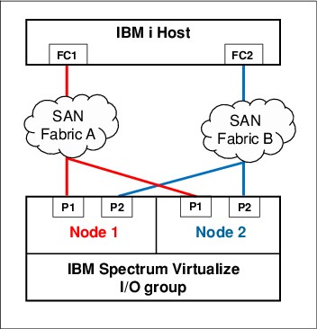
Figure A-10 SAN switch zoning for IBM i with IBM Spectrum Virtualize storage
For VIOS virtual SCSI attachment, zone one physical port in VIOS with one or more available FC ports from each of both node canisters of the IBM Spectrum Virtualize storage I/O group. IBM SAN Volume Controller or IBM Storwize ports that are zoned with one VIOS port must be evenly spread between both node canisters. A maximum of eight host paths is supported from VIOS to IBM Spectrum Virtualize storage.
IBM i Multipath
Multipath provides greater resiliency for SAN-attached storage. IBM i supports up to eight active paths and up to eight passive paths to each LUN. In addition to the availability considerations, lab performance testing shows that two or more paths provide performance improvements when compared to a single path.
Typically, two active paths to a LUN are a good balance of price and performance. The scenario that is shown in Figure A-10 results in two active and two passive paths to each LUN for IBM i. However, you can implement more than two active paths for workloads where high I/O rates are expected to the LUNs where a high I/O access density is expected.
It is important to understand that IBM i multipath for a LUN is achieved by connecting the LUN to two or more FC ports that belong to different adapters in an IBM i partition. Adding more than one FC port from the same IBM Spectrum Virtualize storage node canister to a SAN switch zone with an IBM i FC initiator port does not provide more active paths because an IBM i FC initiator port, by design, logs in to one target port of a node only.
With IBM i native attachment, the ports for multipath must be from different physical FC adapters in IBM i. With VIOS NPIV, the virtual Fibre Channel adapters for multipath must be assigned to different VIOS for redundancy. However, if more than two active paths are used, you can use two VIOS and split the paths among them. With VIOS virtual SCSI attachment, the virtual SCSI adapters for IBM i multipath must be assigned to different VIOS.
IBM Spectrum Virtualize storage uses a redundant dual active controller design that implements SCSI asymmetrical logical unit access (ALUA). That is, some of the paths to a LUN are presented to the host as optimized and others as nonoptimized.
With an ALUA aware host, such as IBM i, the I/O traffic to and from a specific LUN normally goes through only the optimized paths, which often are associated with a specific LUN of preferred node. The nonoptimized paths, which often are associated with the nonpreferred node, are not actively used.
In the case of an IBM Spectrum Virtualize storage topology, such as HyperSwap or IBM SAN Volume Controller Enhanced Stretched Cluster that implements host site awareness, the optimized paths are not necessarily associated with a preferred node of a LUN but with the node of the I/O group that includes the same site attribute as the host.
If the node with the optimized paths fails, the other node of the I/O group takes over the I/O processing. With IBM i multipath, all of the optimized paths to a LUN are reported as active on IBM i, while the nonoptimized paths are reported as passive. IBM i multipath employs its load balancing among the active paths to a LUN and starts the use of the passive paths if all active paths failed.
Boot from SAN
All IBM i storage attachment options that are native (VIOS NPIV, and VIOS virtual SCSI), support IBM i boot from SAN. The IBM i load source is on an IBM Spectrum Virtualize storage LUN that is connected in the same manner as the other LUNs.
Apart from the required minimum size, the load source LUN does include any special requirements. The FC or SCSI I/O adapter for the load source must be tagged (that is, specified) by the user in the IBM i partition profile on the IBM Power Systems Hardware Management Console (HMC). When installing the IBM SLIC with disk capacity on IBM Spectrum Virtualize storage, the installation prompts you to select one of the available LUNs for the load source.
IBM i mirroring
Some clients prefer to use IBM i mirroring functions for resiliency. For example, they use IBM i mirroring between two IBM Spectrum Virtualize storage systems, each connected with one VIOS.
When setting up IBM i mirroring with VIOS connected IBM Spectrum Virtualize storage, add the LUNs to the mirrored ASP by completing the following steps:
1. Add the LUNs from two virtual adapters with each adapter connecting one to-be mirrored half of the LUNs.
2. After mirroring is started for those LUNs, add the LUNs from another two new virtual adapters, each adapter connecting one to-be mirrored half, and so on. This way, you ensure that IBM i mirroring is started between the two IBM Spectrum Virtualize storage systems and not among the LUNs from the same storage system.
Copy services considerations
This section describes IBM Spectrum Virtualize Copy Services considerations for usage with IBM i.
Remote replication
The IBM Spectrum Virtualize family products support Metro Mirror synchronous remote replication and Global Mirror asynchronous remote replication.
Two options are available for Global Mirror: Standard Global Mirror, and Global Mirror with change volumes, which allows for a flexible and configurable recovery point objective (RPO) that allows data replication to be maintained during peak periods of bandwidth constraints, and data consistency at the remote site to be maintained and also during resynchronization.
Regarding the IBM Spectrum Virtualize Copy Services functions, the IBM i single-level storage architecture requires that the disk storage of an IBM i system needs to be treated as a single entity; that is, the scope of copying or replicating an IBM i disk space must include SYSBAS, which is referred to as full system replication, or an IASP (referred to IASP replication).
Full system replication is used for disaster recovery (DR) purposes where an IBM i standby server is used at the DR site, as shown in Figure A-11 on page 626. When a planned or unplanned outage occurs on the IBM i production server, the IBM i standby server can be started (IPLed) from the replicated SYSBAS volumes after they are switched from IBM Spectrum Virtualize to a primary role to become accessible for the IBM i standby host.
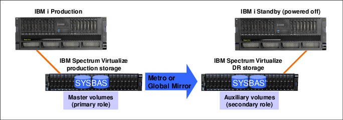
Figure A-11 IBM i full system replication with IBM Spectrum Virtualize
IASP-based replication for IBM i is used for a high availability (HA) solution in which an IBM i production and an IBM i backup node are configured in an IBM i cluster and the IASP that is replicated by IBM Spectrum Virtualize remote replication is switchable between the two cluster nodes, as shown in Figure A-12.
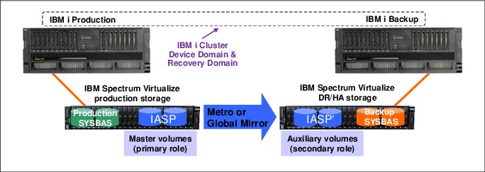
Figure A-12 IBM i IASP replication with IBM Spectrum Virtualize
In this scenario, the IBM i production system and the IBM i backup system each have their own non-replicated SYSBAS volumes and only the IASP volumes are replicated. This solution requires IBM PowerHA SystemMirror® for i Enterprise Edition (5770-HAS *BASE and option 1) for managing the IBM i cluster node switch and failovers and the IBM Spectrum Virtualize storage remote replication switching.
In this scenario, the IBM i production system and the IBM i backup system each have their own nonreplicated SYSBAS volumes and only the IASP volumes are replicated. This solution requires IBM PowerHA SystemMirror for i Enterprise Edition (5770-HAS *BASE and option 1) for managing the IBM i cluster node switch and fail overs and the IBM Spectrum Virtualize storage remote replication switching.
For more information about IBM i high availability solutions with IBM Spectrum Virtualize Copy Services see PowerHA SystemMirror for IBM i Cookbook, SG24-7994.
The sizing of the required replication link bandwidth for Metro Mirror or Global Mirror must be based on the peak write data rate of the IBM i workload to avoid affecting production performance. For more information, see “SAN Extension design considerations” on page 299.
For more information about IBM Spectrum Virtualize storage zoning guidelines, see 2.3.2, “Port naming and distribution” on page 49.
For environments that use remote replication, a minimum of two FC ports is suggested on each IBM Spectrum Virtualize storage node that is used for remote mirroring. The remaining ports on the node should not have any visibility to any other IBM Spectrum Virtualize cluster. Following these zoning guidelines helps to avoid configuration-related performance issues.
FlashCopy
When planning for FlashCopy with IBM i, make sure that enough disk drives are available to the FlashCopy target LUNs to maintain a good performance of the IBM i production workload while FlashCopy relationships are active. This guideline is valid for FlashCopy with and without background copy.
When FlashCopy is used with thinly provisioned target LUNs, ensure that sufficient capacity is available in the storage pool to be dynamically allocated when needed for the copy-on-write operations. The required thin target LUN capacity depends on the amount of write operations to the source and target LUNs, the locality of the writes, and the duration of the FlashCopy relationship.
FlashCopy temperature and considerations for IBM i
FlashCopy temperature indicates the amount of disruption to source system and quality of the FlashCopy target. FlashCopy copies what was sent to disk. Updates that are sitting in memory on the IBM i are not known to the storage system.
FlashCopy cold
The following considerations apply to FlashCopy cold:
• All memory is flushed to disk.
• Source IASP must be varied off before performing a FlashCopy.
• This method is the only method to ensure all writes are sent out to disk and included.
FlashCopy warm
The following considerations apply to FlashCopy warm:
• Memory is not flushed to disk.
• Writes in memory are excluded from the FlashCopy target.
• Zero disruption to IBM i source system.
FlashCopy quiesced
IBM i provides a quiesce function that can suspend database transactions and database and Integrated File System (IFS) file change operations for the system and configured basic auxiliary storage pools (ASPs) or independent ASPs (IASPs).
Consider the following points about FlashCopy quiesced:
•Some memory is flushed to disk.
•Attempts to flush writes to disk and suspends DB I/O and to reach commitment control boundaries.
•Minimal disruption to source, is the preferred practice, and better quality than warm.
HyperSwap
IBM Spectrum Virtualize storage HyperSwap as an active-active remote replication solution is supported for IBM i full system replication with IBM i 7.2 TR3 or later. It is supported for native and for VIOS NPIV attachment.
HyperSwap for IBM i IASP replication is supported by IBM i 7.2 TR5 or later and by IBM i 7.3 TR1 or later. With this solution, you must install IBM PowerHA SystemMirror for i Standard Edition (5770-HAS *BASE and option 2) that enables LUN level switching to site 2. It is supported for native and VIOS NPIV attachment.
IBM Spectrum Virtualize HyperSwap relies on the SCSI ALUA aware IBM i host multipath driver to manage the paths to the local and remote IBM Spectrum Virtualize storage systems that are logically configured as a single clustered system.
From a SAN switch zoning perspective, HyperSwap requires that the IBM i host is zoned with IBM Spectrum Virtualize nodes of the I/O group on each site. For a balanced configuration, the SAN switch from a dual fabric configuration is evenly used.
An example of the SAN fabric connections for IBM i HyperSwap with VIOS NPIV attachment is shown in Figure A-13. This configuration example results in four active paths and 12 passive paths that are presented on IBM i for each HyperSwap LUN.

Figure A-13 IBM i HyperSwap SAN fabric connection example
Next, we briefly describe some high availability scenarios that use HyperSwap for IBM i.
Outage of Spectrum Virtualize I/O group at site 1
In this scenario, the entire IBM i storage capacity is on HyperSwap LUNs.
After the outage of I/O group at site 1 occurs, the I/O rate automatically transfers to the IBM Spectrum Virtualize nodes at site 2. The IBM i workload keeps running, and no relevant messages exist in IBM i message queues.
When the outage finishes, the IBM i I/O rate automatically transfers to nodes on site 1. The IBM i workload keeps running without interruption.
Disaster at site 1 with full system HyperSwap
In this scenario, we use a prepared IBM i standby system at site 2. The entire IBM i storage capacity is on HyperSwap LUNs. Two hosts are defined in the IBM Spectrum Virtualize storage cluster: one host with the WWPNs of IBM i at site 1, and one with WWPNs of site 2.
After a failure of site 1, including a failure of the IBM i production system and the storage at site 1, the IBM i LUNs are still available from the IBM Spectrum Virtualize nodes at site 2.
In the HyperSwap cluster, we manually unmap the HyperSwap LUNs from the IBM i production host at site 1, map the LUNs to the IBM i standby host at site 2, and IPL the IBM i standby host at site 2. After the IPL completes, we can resume the workload on site 2.
After the outage of site 1 is finished, power-down IBM i at site 2, unmap the IBM i LUNs from the host at site 2 and then, map them to the host at site 1. IPL IBM i at site 1 and resume the workload. The I/O rate is transferred to the IBM Spectrum Virtualize storage nodes at site 1.
Disaster at site 1 with IASP HyperSwap
This scenario requires IBM PowerHA SystemMirror for i software to be installed. It also needs the corresponding IBM i setup that consists of two IBM i partitions in a cluster and a switchable IASP on IBM i at site 1, a PowerHA cluster resource group, and PowerHA copy description. The workload is running in the IASP.
For more information about PowerHA for i setup, see IBM PowerHA SystemMirror for i: Preparation (Volume 1 of 4), SG24-8400.
In this scenario, ensure that all IBM i LUNs, not just the IASP LUNs, are HyperSwap volumes.
If a disaster occurs at site 1, PowerHA automatically switches the IASP to the system at site 2, and the workload can be resumed at site 2.
After the failure at site 1 is fixed, use PowerHA to switch the IASP back to site 1 and resume the workload at this site.
Planned outage with Live Partition Mobility
IBM PowerVM Live Partition Mobility (LPM) allows you to move a running logical partition (including its operating system and running applications) from one system to another without any shutdown or disruption to operation of that logical partition.
In this scenario, LPM is combined with HyperSwap to transfer the workload onto site 2 during a planned outage of site 1. This combination requires VIOS NPIV attachment and all IBM i LUNs configured as HyperSwap LUNs.
For more information about LPM and its requirements, see IBM PowerVM Virtualization Introduction and Configuration, SG24-7940.
To use LPM, you must define the IBM i host in IBM Spectrum Virtualize with the WWPNs of the second port of the virtual FC adapters. We recommend creating a separate host object definition for the secondary ports to specify site 2 for this host object. Then, you enable the I/O rate to be transferred to the nodes at site 2 after migrating the IBM i partition with LPM.
After the outage is completed, you can use LPM again to transfer the IBM i partition back to site 1. After the migration, the I/O rate automatically moves to the nodes at site 1.
|
Important: LPM now supports multiple client virtual FC (vFC) adapter ports being mapped to a single physical FC port. Each client virtual FC must be mapped to a separate physical port in advance, whether LPM with FC N_Port ID Virtualization is used. That restriction was removed for the use of Virtual I/O Server version 3.1.2.10 or later and IBM i 7.2 or later. Therefore, the same physical port can be double-mapped to the same IBM i client partition. This configuration allows for better use of the adapter.
|
IBM Db2 mirroring for IBM i
The Db2® Mirror base configuration consists of two systems that are in the same data center. This configuration cannot span locations because it is active-active read/write, which mean that by definition, all write operations are synchronous (by using Remote Direct Memory Access [RDMA] over Converged Ethernet [RoCE] network) to the application state. The write operations between two systems necessitate that the distances between the systems are limited to not affect performance.
The following two broad approaches are used to deploy active-active solutions:
•Distributed lock management, in which multiple application servers can access the common or shared database but are prevented from performing simultaneous updates by the distributed lock management, which locks out the other users while an update is done.
•The replication approach, in which each update of any type is synchronous to the application state. When an application has an update, it does not proceed to the next application step until the current write operations completed on the primary and secondary objects. This replication approach is referred to as a two-phase commit between two systems.
|
Note: Applications can be deployed in an active-active manner, in which each application server has simultaneous access to the database on both systems in the two-node active-active complex. If one of the database servers fails, the application servers continue performing I/O operations to the other system in the mirrored pair. This configuration includes the added benefit of enabling workload balancing.
|
However, applications also can be deployed in an active-passive manner, where application servers conduct write operations to one of the two systems in the two-system complex and, if the primary is removed, the application groups are switched to the secondary system.
The active-active case necessitates that the application servers be hosted separately from the database servers and be connected through a client/server construct, such as Java Database Connectivity (JDBC).
|
Note: IBM i JDBC drivers now contain alternative server fail-over support to automatically transition the JDBC request between systems when one connection is no longer available. For many IBM i application workloads, deployment is through the traditional 5250 emulation window and contained in the same LPAR as the operating system and database. In this case, if the primary fails, the database is continuously replicated to the secondary system synchronously and is immediately available. The application must be restarted on the secondary system before the workload processing is resumed.
|
When one of the systems in the Db2 Mirror configuration is unavailable, Db2 Mirror tracks all update, change, and delete operations to the database table and all other mirror-eligible objects. When the pair is reconnected, changes are synchronized between the systems, including databases that are in an Independent Auxiliary Storage Pool (IASP) or are part of the base system storage.
Db2 Mirror is compatible with IASPs and uses IASPs for IFS support within the Db2 Mirror configuration. For non-IFS objects, IASPs can be used, but are not required.
In addition, Db2 Mirror supports applications that use traditional record-level access or SQL-based database access. Support for IFS and IFS journals is accomplished through deployment into an IASP, which can be configured as a switchable LUN or in a mirrored pair of IASPs through storage replication.
This solution requires the following software:
•IBM Power Systems POWER8® or later
•IBM i 7.4 with IBM Db2 Mirror for i V7.4 (5770-DBM)
•IBM i Option 48 and Db2 Data Mirroring are required for Db2 Mirror for i. Therefore, entitlement for Option 48 is automatically included with Db2 Mirror for i orders. Make sure that IBM i Option 48 is installed and a key is applied with the Db2 Mirror for i Licensed Program Product.
For more information about the software requirements for Db2 Mirror see this IBM Documentation web page.
DR can be performed with various options, such as:
•The IBM PowerHA SystemMirror for i Enterprise Edition
•Full system replication
•Logical replication
|
Important: Consider the following points when Db2 Mirror local continuous availability is combined with HA) and DR replication technologies:
•Remote replication for DR can be implemented by storage-based replication; that is, using the Copy Services of IBM Spectrum Virtualize software.
•Integrated File System (IFS) IASP must remain switchable between local Db2 Mirror nodes by choosing a DR topology that is supported by IBM PowerHA SystemMirror for i.
•DB IASP is available on both local nodes (no switch between local nodes).
A DB IASP is not required for local Db2 Mirror database replication, but might be preferred for implementing a remote replication solution with shorter recovery times compared to SYSBAS replication.
•For a complete business continuity solution at the DR site, a remote DB2 Mirror node pair can be configured for a four-node Db2 Mirror PowerHA Cluster configuration. IFS IASPs and DB IASPs must be registered with the remote DB2 Mirror pair (by using the SHADOW option for the DB IASP to maintain its Db2 Mirror configuration data, such as default inclusion state and RCL).
For more information, see IBM Db2 Mirror for i Getting Started, REDP-5575.
|
Overview of the setup process
The following node types are part of the setup and configuration of Db2 Mirror:
•Managing
•Setup source
•Setup copy mode
For more information about the nodes, setup, and configuration, see this IBM Documentation web page.
Db2 Mirror is initially configured on a single partition, which is the setup source node. During the setup and configuration process, the setup source node is cloned to create the second node of the Db2 Mirror pair, which is the setup copy node. The setup copy node is configured and initialized automatically by Db2 Mirror during its first IPL.
The Db2 Mirror configuration and setup process supports external and internal storage. For the external storage that is used during the cloning process, IBM storage systems are recommended rather that non-IBM external storage because Db2 Mirror automates the cloning for IBM Spectrum Virtualize family.
The following cloning technologies are used for IBM storage systems:
•FlashCopy (cold and warm) is used when both Db2 Mirror nodes connect to the same IBM Spectrum Virtualize storage system. Consider the following points:
– A cold clone requires the setup source node to be shut down during the cloning portion of the setup process.
– A warm clone allows the setup source node to remain active during the entire Db2 Mirror setup and configuration process.
•Remote Copy is used when the Db2 Mirror nodes are connected to different IBM Spectrum Virtualize storage.
For more information, see this IBM Documentation web page.
|
Note: Although volume mirroring that is supported in IBM FlashSystem 9200 and IBM SAN Volume Controller is a valid cloning method for DB2 Mirror in the manual copy category, it is not automated, unlike the use of FlashCopy, Metro Mirror, or Global Mirror, where mirroring is automated.
|
IBM Spectrum Virtualize and Db2 Mirror
IBM Spectrum Virtualize storage systems establish communication with Db2 Mirror by using Secure Shell (SSH) to manage Copy Services functions. By IBM Spectrum Virtualize user IDs must have the administrator role. In that context, the following products are mandatory for managing nodes:
•5733SC1 *BASE IBM Portable Utilities for i
•5733SC1 Option 1 OpenSSH, OpenSSL, zlib
•5770SS1 Option 33 Portable Application Solutions Environment
|
Note: For more information about creating an SSH key pair, see this IBM Documentation web page. After an SSH key pair is created, attach the SSH public key to a use on the IBM Spectrum Virtualize storage system. The corresponding private key file must be uploaded to the managing node so it can be used during DB2 Mirror setup.
|
Virtual I/O Server and native attachment
The Db2 Mirror storage cloning process for IBM Spectrum Virtualize requires Fibre Channel adapters with native attachment or attachment with Virtual I/O Server N_Port ID Virtualization.
Host object definition and volume planning
Before you set up Db2 Mirror, you must define the host object and assign volumes to the hosts to be used by the setup copy node. The following prerequisites must be met:
•The same number of host objects and volumes are available
•The same size volumes are defined for the setup source node and setup copy node
The Db2 Mirror cloning process pairs storage volumes between the setup source node and setup copy node. The cloning process applies to SYSBAS and IASPs:
•The setup source node and setup copy node must have the same number and sizes of LUNs or disks in SYSBAS.
•The host object and volumes for any database IASPs must be predefined for the setup copy node before a database IASP is added to DB2 Mirror.
Remote Copy cloning
Db2 Mirror Remote Copy cloning uses the following IBM Spectrum Virtualize Copy Services operations to copy the setup source node volumes to the setup copy nodes volumes:
•Global Mirror for cold clone
•GMCV for warm clone
Regardless of whether you plan to perform the Remote Copy during a planned outage window, you must ensure that your bandwidth between storage systems is sufficient to complete the Remote Copy during that period. The Db2 Mirror cloning process does not provide the capability of pausing the cloning and then resuming it later. Therefore, you must plan enough time for the Remote Copy to complete.
|
Important: For IBM Spectrum Virtualize, the Copy Services partnership between storage systems must be manually created before Db2 Mirror is configured.
|
Architectures and considerations for DB2 Mirror
Because of the synchronous design of Db2 Mirror, the distance between the nodes is limited to within a data center in most cases. Multiple configurations are supported for a data center Db2 Mirror implementation and the addition of a DR solution.
Several options are discussed in this section as examples with IBM Spectrum Virtualize storage systems. A specific implementation depends on your business resilience requirement.
|
Note: Db2 Mirror supports IBM SAN Volume Controller topologies, such as Enhanced Stretched Cluster or HyperSwap.
|
Db2 Mirror environment with one IBM Spectrum Virtualize storage system
In this example, one IBM Spectrum Virtualize storage system is used as a basic configuration for the use of Db2 Mirror. This configuration features some key advantages.
By using one storage system, you can take advantage of FlashCopy to set up your configuration rapidly. You can consider this solution as a DR strategy to provide storage resiliency.
Figure A-14 shows two IBM Power System servers are used (at least one RoCE adapter per server). However, you can reduce this scenario in terms of cost of decreased resiliency by implementing Db2 Mirror across two IBM i LPARs on the same IBM Power Systems. For this example, a SYSBAS is cloned; however, IASP also can be added by using another set of volumes.

Figure A-14 Db2 Mirror environment with one IBM Spectrum Virtualize storage
DB2 Mirror environment with two IBM Spectrum Virtualize storage systems
The use of two IBM Spectrum Virtualize storage systems provides further redundancy by helping to ensure that the active node remains running and available during a storage outage. In this example, two IBM Power Systems servers and IBM Spectrum Virtualize storage systems are used. Also, Remote Copy is used to set up DB2 Mirror.
As shown in Figure A-15, the set of volumes for SYSBAS and the set of volumes for IASP are replicated. Global Mirror can also be used.

Figure A-15 Db2 Mirror environment with two IBM Spectrum Virtualize storages
Db2 Mirror and DR considerations
Db2 Mirror is a continuous availability solution, but it is not considered a DR solution. However, Db2 Mirror can be used within your DR strategy to improve your availability, even within a disaster situation.
The Db2 Mirror nodes must be close to each other because the maximum distance between IBM Power Systems servers is 200 meters (656 feet). Consider the following points:
•At Site 1 (the continuous-availability location), Db2 Mirror nodes are used.
•At Site 2 (the DR location), you can have a single server or multiple servers with Db2 Mirror nodes can b, and a unique or multiple IBM Spectrum Virtualize storage systems.
The communication between the continuous availability at Site 1 and the DR at Site 2 can be achieved by using specific technology, such as the following examples:
•IBM PowerHA SystemMirror for i using Metro Mirror
•Global Mirror with IASPs
•Full system replication
•Logical replication from third-party vendor
Db2 Mirror and full system replication
The use of a mirrored pair within the disaster site provides extra protection if you are required to role-swap to the DR location. With this scenario, a continuously available environment exists in DR.
A topology with multiple IBM Spectrum Virtualize storage systems and multiple IBM Power Systems servers is shown in Figure A-16.

Figure A-16 DB2 Mirror and full system replication
Full system replication is fully supported. If IASP is not used, this type of replication can be done for IBM i at the IBM Spectrum Virtualize storage level.
In Figure A-16, the following sites are configured:
•Site 1: Db2 Mirror with DR and Db2 Mirror production
At Site 1, an active side exists because of full system replication.
•Site 2: Db2 Mirror with DR
At Site 2, the IBM i systems are powered off, and the replication is active across sites.
Two copies are at a DR location because if one side fails, the other side must continue replicating. If only three nodes are replicating, you cannot predict which side fails and does not have a valid copy of storage to switch.
..................Content has been hidden....................
You can't read the all page of ebook, please click here login for view all page.