Chapter 6. Cisco Firewalls: Appliance and Module
The firewall has become a common entity and is a necessary and integral part of every network infrastructure. The most critical requirement in most security solutions today is implementing a firewall. Networks today have grown both in size and complexity, with the environment becoming increasingly hostile. This chapter brings together Cisco industry-leading innovative firewall technology with flagship products uniquely positioned to deliver purpose-built, feature-rich firewall technology.
The previous chapter focused on a router-based IOS Firewall solution, whereas this chapter mainly focuses on the hardware-based, purpose-built Cisco Firewall technology.
The chapter discusses various types of Cisco Firewalls available and includes a brief overview of each model. The chapter is divided into two segments—features and configuration based on the following:
• Firewall appliance software for PIX 500 and ASA 5500 platforms
• Firewall module software for Firewall Services Module (FWSM)
The chapter takes a closer look at core concepts, such as firewall modes, security contexts, stateful inspection, the Adaptive Security Algorithm, IP routing, various types of Network Address Translation (NAT), the control of traffic flow and network access through the firewall, the Modular Policy Framework (MPF), and the provisioning of high-availability and resilient networks.
Firewalls Overview
A firewall is a hardware or software solution implemented within the network to enforce security policies by controlling network access. The traditional function of firewalls has evolved from the original function of protecting a network from unauthorized external access. Besides protecting the perimeter of a network, today’s firewalls implement the following: access control, virtual private network (VPN) services, quality of service (QoS) features, redundancy mechanisms, and much more. In general, firewalls can offer data privacy, integrity, and availability.
A firewall is often seen as the first step toward a network security solution. Network security needs to be architected as a foundation for success, and firewalls are an integral part of this architecture.
Firewall deployment requires charting network boundaries between security domains. A network security domain is a contiguous zone of a network that operates under a uniform security policy. A policy enforcement mechanism is required where these domains interconnect. This is where firewall technology comes into play. Firewalls ensure protection by acting as the first line of network defense.
Hardware Versus Software Firewalls
The primary differentiator between a hardware- and software- based firewall is the underlying dependency on the operating systems they run on. Both can prove equally secure if the network design and configuration are impeccable. As seen in the previous chapter, the software-based Cisco IOS Firewall technology is integrated functionality inside the Cisco IOS Software, thereby providing a stateful inspection firewall engine with application-level intelligence. There are a couple of reasons why hardware firewalls are better than software firewalls: hardware firewalls are robust and built specifically for the purpose of “firewalling,” and they are less vulnerable than software firewalls. Hence, hardware firewalls have an edge over software-based firewalls.
The Cisco Firewall technology provides a wealth of advanced security and networking services for small-to-medium enterprise and service provider networks, in a modular, purpose-built solution. Cisco hardware-based firewall technology comes in three flavors:
• PIX 500 Series Security Appliances
• ASA 5500 Series Adaptive Security Appliances
• Catalyst 6500 Series and Cisco 7600 Series Firewall Services Module (FWSM)
Cisco Firewall technology solutions provide application-aware and protocol inspection, access control and flow-based policy enforcement, multi-vector attack protection, and secure connectivity services through a wide range of rich security and networking services. The following sections will briefly highlight features of each platform.
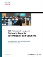
Cisco PIX 500 Series Security Appliances
Cisco flagship and industry-leading PIX 500 Series Security Appliance provides comprehensive security, performance, and reliability for network environments of all sizes, offering an array of multitiered solutions. It is a family of specialized appliances that provide robust integrated network security services, including stateful inspection firewalling, VPNs, and inline intrusion detection.
The dedicated software engine incorporates the state-of-the-art Cisco Adaptive Security Algorithm, which provides stateful inspection firewall services by monitoring the state of all authorized network communications while preventing unauthorized network access. Cisco PIX Security Appliances offer an additional layer of security by integrating more than two dozen purpose-built inspection engines that perform in-depth packet examination for the most common applications and protocols used today. The Cisco PIX Security Appliance provides a wide range of integrated security services in an easy-to-deploy, high-performance solution.
THe Cisco PIX 500 Series range from desktop appliances for small and home offices to modular gigabit appliances for enterprise and service-provider environments, as shown in Table 6-1. (Note that photos are not available for the Cisco PIX 506E and Cisco PIX 515E.)
Table 6-1. Cisco PIX 500 Series Devices
Note
Cisco PIX 506, 515, and 520 Firewall models have reached end of sale (EOS).
Cisco ASA 5500 Series Adaptive Security Appliances
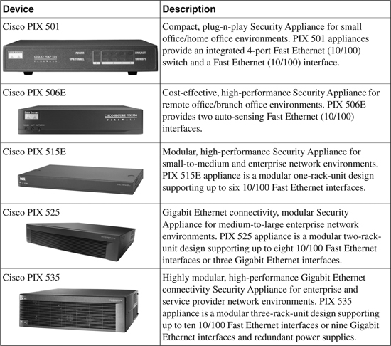
The Cisco ASA 5500 Series Adaptive Security Appliance (Figure 6-1) is the newest member in the group of Cisco Firewall technology products. The ASA 5500 series includes multifunction Security Appliances delivering converged firewall, Intrusion Prevention System (IPS), advanced adaptive threat defense services including Anti-X defenses, application security, and VPN services simplifying network security solutions.
Figure 6-1. Cisco ASA 5500 Series Appliance i
The ASA 5500 Series is one of the key components in the Cisco Self-Defending Network initiative. At the heart of the ASA 5500 Series design is the Adaptive Identification and Mitigation (AIM) architecture that provides proactive threat mitigation, thereby stopping attacks before they spread through the network, network activity controls, and application traffic. The AIM architecture delivers flexible, high-performance site-to-site VPN, remote access VPN, and SSL VPN solutions.
In a single platform, the Cisco ASA 5500 Series offers the following:
• Market-proven firewall, IPS, adaptive threat defense, and VPN capabilities
• Adaptive identification and mitigation services architecture, thereby delivering granular policy control and future services extensibility
• Saving overall deployment and operational costs and reduced complexity
The Cisco ASA 5500 Series is an innovative appliance that builds on the depth and breadth of security features, combining the following three industry-leading security and VPN technologies:
• Firewall technology
• IPS (inline) technology
• VPN technology—IPsec, SSL (WebVPN), and AnyConnect VPN
Blending these multiple functions, the Cisco ASA 5500 Series delivers an unmatched best-of-breed in network protection solutions. The Cisco ASA 5500 Series brings together a wide range of security and VPN technologies to provide rich application security, Anti-X defenses, network containment and control, and secure connectivity tightening the network security posture.
Cisco ASA 5500 Series offer five high-performance purpose-built appliances that span small- and medium-sized to large enterprise and service provider environments. Concurrent security services architecture lowers operational complexity and reduces the overall deployment and operation costs.
• ASA 5505: Cost-effective, easy-to-deploy appliance for small business, branch office, and enterprise teleworkers environments with integrated 8 port 10/100 Fast Ethernet switch (includes two Power over Ethernet [PoE] ports)
• ASA 5510: Cost-effective, easy-to-deploy appliance for medium-sized business, remote/branch, and enterprise environments with advanced security and networking services
• ASA 5520: High-availability Active/Active services and Gigabit Ethernet connectivity appliance for medium-sized enterprise networks, in a modular, high-performance network
• ASA 5540: High-density, with Active/Active high-availability services and Gigabit Ethernet connectivity with greater reliability, high-performance appliance for medium-to-large enterprises and service-provider networks
• ASA 5550: Gigabit-class offering up to 1.2 Gbps firewall throughput, with Active/Active high-availability services, and Fiber and Gigabit Ethernet connectivity; high-performance appliance for large enterprise and service-provider networks
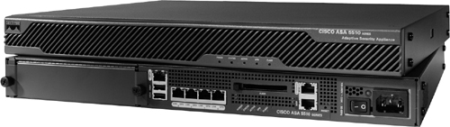
Cisco Firewall Services Module (FWSM)
Cisco Firewall Services Module (FWSM), pictured in Figure 6-2, is a high-speed, high-performance integrated firewall module that is installed in Cisco Catalyst 6500 switches and Cisco 7600 Series routers.
Figure 6-2. Cisco Firewall Services Module (FWSM)
The FWSM provides large enterprises and service providers with unparalleled security, reliability, scalability and performance. Some of the key features in FWSM are the following:
• Integrated module: Installs inside a Cisco Catalyst 6500 Series Switch or Cisco 7600 Series Router. The FWSM integrates firewall security inside the network infrastructure.
• Superior performance and scalability: The FWSM offers the fastest firewall solution in the industry, with unprecedented data rates. FWSM can handle up to 5 Gbps of traffic, 100,000 connections per second (cps), and 1 million concurrent connections, thereby providing unsurpassed performance to meet future requirements. With the capacity to install up to four FWSMs in a single chassis, throughput performance is enhanced to 20 Gbps per chassis to meet growing demands.
• Proven technology: The FWSM software is based on Cisco PIX technology and uses the same time-tested Cisco PIX Operating System, a secure, real-time operating system.
• Lower TCO (total cost of ownership): Virtualized FWSM delivers multiple firewalls on one physical hardware platform. Virtualization reduces the number of physical devices required in a network, thereby significantly minimizing the complexity of managing network infrastructure and operational efficiency.
• ROI (return on investment): Higher ROI with flexible deployment leveraging existing infrastructure investments.
Firewall Appliance Software for PIX 500 and ASA 5500
Cisco Firewall Appliance provides integrated hardware and software delivering full stateful firewall protection and VPN capabilities. It provides in-depth packet inspection and flow-specific monitoring, improved network integration, resiliency, and scalability. Unlike typical CPU-intensive proxy servers, the Cisco Firewall Software uses a non-UNIX secure, real-time, embedded system.
Both appliances (PIX 500 and ASA 5500 series) are based on the industry-leading Cisco Firewall Software currently on version 8.0 as of this writing. The majority of the functions are the same on both appliances, with the exception that in comparison to the PIX 500 series, the ASA 5500 series has the additional support of SSL VPN technology (WebVPN), VPN Load Balancing, the Security Services Module (SSM)—IPS module, Compact Flash (CF) card support, and Aux port support.
Note
PIX 501 and 506E models do not support the new firewall software versions. They are capable of running up to version 6.3 only.
Firewall Appliance OS Software
Cisco Security Appliance software for firewalls delivers the latest firewall and VPN capabilities, enhanced performance, and security improvements, as well as a list of new features. Version 7.0 and the latest release, version 8.0, introduce significant enhancements to all major functional areas. These areas include firewalling and inspection services such as transparent (Layer 2) firewall or routed (Layer 3) firewall operation and multiple security contexts (virtualized firewalls), Enhanced Interior Gateway Routing Protocol (EIGRP) support, Application-Aware Inspection Services, enhanced VPN services, Dynamic Access Policies (DAP), browser-based SSL VPN, network integration, high availability (Active/Active) and enhanced management and monitoring services.
Some of the advanced features include TCP stream reassembly, which assists in detecting attacks that are spread across multiple packets (fragmented) by reassembling packets into a full packet stream and performing analysis on the entire stream.
Another feature, TCP normalization, provides improved techniques to detect TCP-based attacks and is designed to drop packets that do not appear normal. A strict inspection is performed to confirm RFC compliance on the TCP header (advanced header examination for flags and checking option, window variation, checksum verification and detection of data tampering in retransmitted packets). Several other advanced features and enhancements are available in the more recent software version releases.
The Security Appliance combines in one device advanced stateful firewall, VPN concentrator functionality, and advanced protection features to intercept and respond to network attacks.
The Security Appliance software supports an intuitive, easy-to-use GUI-based application called Adaptive Security Device Manager (ASDM). ASDM is a browser-based Java applet used to configure, monitor, and manage the Security Appliances. ASDM is covered in Chapter 24, “Security and Policy Management.”
With the brief introduction and product overviews, sections to follow will discuss the features and the configuration details.
Firewall Modes
The Security Appliance runs in two firewall modes:
• Routed firewall mode
• Transparent firewall mode (stealth firewall)
Routed Firewall Mode
In this mode, the Security Appliance is considered to be a router hop in the network. (This is the regular mode that everyone is familiar with.) Network Address Translation and dynamic routing protocol capabilities using Routing Information Protocol (RIP) and Open Short Path First (OSPF) can be performed in this mode. Note that routing protocols RIP and OSPF are supported in single context mode only. Multimode context does not support routing. In addition, routed mode supports use of multiple interfaces. Each interface must be on a different subnet, and interfaces can be shared between contexts. By default, routed mode is set as the default mode.
Transparent Firewall Mode (Stealth Firewall)
Firewall Software Version 7.0 and later introduces the capability to deploy the Security Appliance in a secure bridging mode, as a Layer 2 device, to provide rich Layer 2 through 7 firewall services. In a transparent mode, the Security Appliance acts like a “bump in the wire” and is not a router hop. There is no need to redesign the IP network (Layer 3 addressing scheme). The Security Appliance connects the same network (IP subnet) on its inside and outside interfaces. The inside and outside interfaces are put on different Layer 2 segments if they are connected on the same switch (use unique VLAN numbers or use separate switches).
In essence, the network is split into two Layer 2 segments and the appliance is placed in between, thereby acting in bridge mode, and Layer 3 remains unchanged. Alternatively, clients can be connected on either side into two separate switches that are independent of each other (and not connected to each other in any way).
Figure 6-3 illustrates this further. Even though the firewall is in the bridge mode, an ACL is still required to control and allow all Layer 3 traffic that is passing through the firewall, with the exception of ARP traffic, which does not need an ACL. ARP traffic can be controlled with ARP inspection on the firewall.
Transparent mode does not support IP routing protocols for traffic passing through the router, because the firewall is in bridge mode. Static routes are used for traffic originating from the appliance and not for traffic traversing the appliance. However, IP routing protocols through the firewall are supported, as long as the access lists on the firewall permit the protocols to pass through. OSPF, RIP, EIGRP, and Border Gateway Protocol (BGP) adjacencies can be established through the firewall in the transparent mode.
While running in transparent mode, the Security Appliance continues to perform the stateful inspection with application-layer intelligence and perform all regular firewalling capabilities, including NAT support. NAT configuration is supported in software version 8.0 and later. Prior to version 8.0, NAT was not supported in transparent mode.
The egress interface for the outgoing packets is determined by performing a MAC address lookup instead of a route lookup. The only Layer 3 addressing required on the firewall is the management IP address. The management IP address is also used as the source IP address for packets originating from the Security Appliance, such as system messages or communications with AAA or SYSLOG servers. The management IP address must be on the same subnet as the connected network.
Transparent mode is a good technique to protect the network passively (camouflage) without the intruder/attacker detecting the existence of the firewall.
Figure 6-3 shows an example of transparent firewall implementation. The example shows three client workstations with the default gateway set to upstream router 10.1.1.1. Note that all PCs, the upstream router, and the management IP address are in the same IP subnet 10.1.1.0/24, but they have been split in different Layer 2 VLANs because all the devices in the diagram are connected into the same switch. Client workstations and the inside interface of Security Appliance are set in VLAN 10, and the upstream router and outside interface are set to VLAN 20. Note that if clients and all devices on both sides are connected to separate switches, and the switches are not connected to each other in any way, the VLAN numbers can be the same, or anything for that matter, because they are independent and do not interconnect.
Figure 6-3. Transparent Firewall Setup
Stateful Inspection
Every inbound packet is inspected against the adaptive security algorithm and the connection state information to decide whether to allow or deny the packet. Like the PIX and ASA Security Appliance, a stateful firewall checks the state of a packet as follows:
1 Is this a new connection?
If the arriving packet is part of a new connection, the Adaptive Security Algorithm checks the packet against access lists and performs other routine tasks (such as route lookup) to determine whether the packet is allowed or denied. The session management path is responsible for performing the following:
• Perform the access list checks
• Perform route lookups
• Allocate NAT translations (xlate table)
• Establish the session in the “fast path”
Packets are further passed to the control plane path to examine the payload for application-level (Layer 7) inspection.
2 Is this an established connection?
If the arriving packet is part of an existing connection, the Adaptive Security Algorithm does not reexamine the packet, and matching packets in the established connection table can go through the fast path in both directions. The fast path is responsible for performing the following checks:
• IP checksum verification
• Session lookup
• TCP sequence number check
• NAT translations based on existing sessions
• Layer 3 and Layer 4 header adjustments
In some instances, established session packets must continue to go through the session management path or the control plane path for protocols that require Layer 7 inspection. For example, HTTP packets requiring content filtering need to go through the session management path.
Application Layer Protocol Inspection
In addition to the stateful-inspection previously discussed, the Adaptive Security Algorithm is enhanced with powerful capabilities and is built with application-layer intelligence that assists in detecting and preventing protocol and application-layer attacks. It performs deep packet inspection of application-layer protocol traffic (such as HTTP) by checking the packet IP header and the payload contents. Conventional firewalls maintain the session information details up to Layer 4, whereas the Security Appliance adds another tier of security by extending its inspection in the data payload at Layer 7.
With the application-layer awareness, Security Appliance performs deep packet inspection in the data payload for any malicious activity. As shown in Figure 6-4, when the Security Appliance receives a packet that is of well-known application protocol (such as HTTP), it further examines the packet for respective application operation to check for adherence to RFC standards and compliance operations to ensure there is no malicious intent. If the packet is crafted maliciously with unauthorized, nonstandard activity and found to be performing noncompliance operations (illegal commands), the packet is blocked. In a conventional access-list filtering, this packet would be allowed, because only the Layer 3 and Layer 4 information in the packet would be checked.
The Security Appliance armed with the application intelligence provides protection from several types of network attacks that use the embedding technique to pass malicious traffic encapsulating in well-known application protocols.
Figure 6-4. Application Layer Intelligence
Application inspection is enabled by default for most standard well-known protocols with specific TCP or UDP port numbers. See Table 6-2 for a complete list of supported protocols, with their respective standard compliance enforcement. Security Appliance can be tuned to inform the inspection engine to listen on nonstandard ports. For example, the HTTP port can be changed from a standard TCP/80 to a nonstandard TCP/8080 port. Some protocols cannot be changed; Table 6-2 identifies which protocols can be modified to inspect for nonstandard ports. The Modular Policy Framework Command Line Interface (CLI) is used to change the default settings for application inspection for any application layer inspection (discussed further in this chapter). The MPF is similar to the Cisco IOS Software technique called Modular QoS CLI (MQC).
Adaptive Security Algorithm Operation
Figure 6-5 illustrates how the stateful-inspection and application intelligence works in the Security Appliance. Conceptually, three basic operational functions are performed:
• Access lists: Controlling network access based on specific networks, hosts, and services (TCP/UDP port numbers).
• Connections (xlate and conn tables): Maintaining state information for each connection. This information is used by the Adaptive Security Algorithm and cut-through proxy to effectively forward traffic within established connections.
• Inspection Engine: Perform stateful inspection coupled with application-level inspection functions. These inspection rule sets are predefined to validate application compliance as per RFC and other standards and cannot be altered.
Figure 6-5. Adaptive Security Algorithm Operations
Figure 6-5 is numbered with the operations in the order they occur and are detailed as follows:
1 An incoming TCP SYN packet arrives on the Security Appliance to establish a new connection.
2 The Security Appliance checks the access list database to determine whether the connection is permitted.
3 The Security Appliance creates a new entry in the connection database (XLATE and CONN tables) using the necessary session information.
4 The Security Appliance checks the predefined rule sets in the inspection engine and in case of well-known applications, further performs application-level inspection.
5 At this point, Security Appliance makes a decision whether to forward or drop the packet according to the findings of the inspection engine. The Security Appliance forwards the packet to the desired destination subject to clearance from the application inspection engine.
6 The destination system responds to the initial request returning the packet.
7 The Security Appliance receives the reply packet, performs the inspection, and looks up the connection in the connection database to determine whether the session information matches an existing connection.
8 The Security Appliance forwards the packet belonging to an existing established session.
Table 6-2 lists all the application protocols and details for which the Security Appliance provides application layer inspection capability.
Table 6-2. Application Inspection Engines
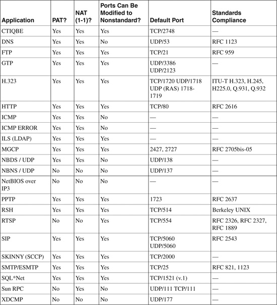
The information in Table 6-2 is taken from “Cisco Security Appliance Command Line Configuration Guide, Version 7.0” at http://www.cisco.com/en/US/docs/security/asa/asa70/configuration/guide/inspect.html#wp1250375.
Security Context
Software Version 7.0 introduced the capability to create multiple virtual firewalls, which are also referred to as security contexts within a single appliance. Multiple contexts are similar to having multiple standalone devices. Each virtualized partition is an independent device and has its own set of security policies (NAT, access list, routing, and so on), logical interfaces, and administrative domain. Multiple contexts mode supports almost all the options that are configurable on a standalone device, such as NAT, firewall features, routing tables, IPS, and management features. Some features, such as VPN and dynamic routing protocols, are not supported in multiple context mode. In addition, interfaces can be shared between contexts but supported in routed mode only. For example, the outside interface can be shared to conserve interfaces, or Inside and demilitarized zone (DMZ) interfaces can be used to share resources between contexts.
There are a number of ways to set up a Security Appliance in multiple mode. The following sections illustrate two common ways for the implementation, including sharing an interface between the contexts.
Multiple Contexts—Routed Mode (with Shared Resources)
Figure 6-6 shows an admin context plus two multiple contexts for multiple departments within an organization, each with three segments: an Inside, an Outside, and a shared segment. Each department has its own security context (virtual firewall) so that it can have its own security policy (NAT, access list, routing, and so on). Several servers are shared across both departments. Hence these servers are placed on a shared network using the shared interface concept.
Figure 6-6. Multiple Contexts—Routed Mode (with Shared Resources)
Multiple Contexts—Transparent Mode
Figure 6-7 shows an admin context plus three multiple contexts for multiple customers in a transparent mode. Each customer has its own security context with its own security policy (NAT, access list, static routes, and so on). A transparent firewall is in a secure bridging mode and connects the inside and outside interfaces to the same network (Net A). Each security context is assigned a management IP address of 10.1.x.2 on the same connected (Net A) IP subnet.
Note
Transparent mode does not allow shared interfaces.
Figure 6-7. Multiple Contexts—Transparent Mode
Note
In multiple mode environments, all contexts can be configured either in routed or transparent mode. Mix-mode environment is not supported.
Caution
Dynamic routing protocols are not supported in multiple context modes; static routing can be used. VPN and Multicast are also not supported.
How does the Security Appliance classify which context to send a packet to?
All packets entering the appliance must be classified to determine which context to send a packet to. The classifier uses the following policy to assign the packet to a context:
1 Unique Interface: If only one context is associated with the ingress interface, the Security Appliance classifies the packet into that context. Note that when using the transparent mode, use unique interfaces only because transparent mode requires unique interface allocation for each context. For routed mode, the following methods also apply.
2 Unique MAC Address: If multiple contexts are associated with the ingress interface, the appliance classifies the packet into a context by matching interface MAC addresses. By default, shared interfaces in a context do not have a unique MAC address, and it uses the default physical MAC address in every context. This can cause ARP issues as an upstream device cannot send the packet to the correct context due to the duplicate MAC address across multiple context interfaces. The solution is to assign a unique MAC address to the shared interface within each context. This can be done using the mac-address mac_address [standby mac_address] command under the interface configuration mode. Alternatively, you can use the global command mac-address auto to automatically generate MAC addresses to each shared context interface.
3 Address Translation: If you are not using unique MAC addresses as just explained, then Security Appliance classifies the packet into a context by matching the destination address to one of the following context configurations. The classifier relies on the NAT configuration and matches the destination IP address in either a static command or global command and looks at the following:
a. Global address in a static NAT statement where the global interface matches the ingress interface of the packet
b. Global NAT pool for IP addresses identified by a global pool for the ingress interface.
Configuring Security Context
To define a context mode, add, or change a context in the system configuration, perform the following steps:
Step 1. Define the context mode (single or multiple). Use the mode {single | multiple} command from the global configuration. The appliance will require a reboot. Note that the mode configuration is not stored in the configuration file.
Step 2. To add or modify a context in the system execution space or the admin context, use the context {name} command from the global configuration mode to enter the context submode. The prompt changes to the following to indicate it is still in the system execution space and is modifying parameters for the specific context:
hostname(config-ctx)#
Step 3. Specify the interface(s) allocated to a context. Enter the command appropriate for a physical interface or for one or more subinterfaces using the allocate-interface command from the context submode. Repeat these commands multiple times to specify different ranges. Note that the transparent firewall mode allows for only two interfaces to pass through traffic. Same interfaces can be assigned to multiple contexts in routed mode, if desired. Transparent mode does not allow shared interfaces.
Step 4. Identify the URL from which the system downloads the context configuration by using the config-url command. Context configuration can be downloaded via several methods, such as internal flash, HTTP/HTTPS, TFTP, or using FTP server.
Step 5. Change between contexts to perform configuration and monitoring tasks within each context by using the changeto context {name} command. The prompt changes to the following:
hostname/context-name#
Step 6. To view the context information, use the show context [name | detail| count] command.
Example 6-1 shows how to enable multiple contexts mode. The example sets the admin-context to be administrator, creates a context called “administrator” on the internal flash memory, and adds another two contexts: a context called customerA from an FTP server, and another context called customerB from internal flash. Note that the context names are case sensitive.
Example 6-1. Configuring Multiple Contexts
hostname(config)# mode multiple
hostname(config)# admin-context administrator
hostname(config)# context administrator
hostname(config-ctx)# allocate-interface Ethernet0.1
hostname(config-ctx)# allocate-interface Ethernet1.1
hostname(config-ctx)# allocate-interface Management0/0
hostname(config-ctx)# config-url flash:/admin.cfg
hostname(config-ctx)# context customerA
hostname(config-ctx)# allocate-interface Ethernet0.100 int1
hostname(config-ctx)# allocate-interface Ethernet0.102 int2
hostname(config-ctx)# allocate-interface Ethernet0.103-Ethernet0.108 int3-int8
hostname(config-ctx)# config-url ftp://joe:[email protected]/configs/
customerA.cfg
hostname(config-ctx)# context customerB
hostname(config-ctx)# allocate-interface Ethernet1.200 int1
hostname(config-ctx)# allocate-interface Ethernet1.202-Ethernet1.203 int2-int3
hostname(config-ctx)# allocate-interface Ethernet1.205-Ethernet1.210 int5-int10
hostname(config-ctx)# config-url flash:/customerB.cfg
Example 6-2 shows how to change between contexts and the system execution space in privileged EXEC mode to perform configuration and monitoring tasks within each context. The system execution space is the admin context from where you can switch between the contexts. Ensure the location, because the configuration changes made are applicable to the current position (within the context). For example, when the show running-config command is executed, it will display only the current configuration of that context and not the running configurations of all contexts (system plus all contexts).
Example 6-2. Changing Between Contexts
hostname/admin# changeto system
hostname# changeto context customerA
hostname/customerA#
OR
hostname# changeto context customerB
hostname/customerB#
Security Levels
The Adaptive Security Algorithm permits connections from one firewall network interface to another by using a security level mechanism. Each interface must be assigned with a security level ranging between 0 (lowest) to 100 (highest). By default, the Security Appliance assigns the internal network (the inside network) security level 100, whereas the external network (outside network) connected to the Internet is assigned with level 0. Other networks, such as DMZ, can be assigned any number in between.
By default, the Security Appliance allows traffic to flow freely from an internal network (higher security level 100) to an external network (lower security level 0).
For traffic to flow between the interfaces through the Security Appliance, basic parameters need to be configured. These include the interface name, security level, an IP address, and the dynamic or static routing and enabling of the interface as physical interfaces are shut down by default.
Example 6-3 shows how to configure physical interface parameters in single mode.
Example 6-3. Configuring Interface Parameters in Single Mode
hostname(config)# interface Ethernet1
hostname(config-if)# nameif inside
hostname(config-if)# security-level 100
hostname(config-if)# ip address 10.1.1.1 255.255.255.0
hostname(config-if)# no shutdown
Example 6-4 shows how to configure interface parameters in multiple contexts mode for the system configuration. The example creates a subinterface Ethernet1.100, by putting it in VLAN 100 allocating the Ethernet1.100 subinterface to contextA.
Example 6-4. Configuring Interface Parameters in Multiple Mode
hostname(config)# interface Ethernet1
hostname(config-if)# speed 100
hostname(config-if)# duplex full
hostname(config-if)# no shutdown
hostname(config-if)# interface Ethernet1.100
hostname(config-subif)# vlan 100
hostname(config-subif)# no shutdown
hostname(config-subif)# context contextA
hostname(config-ctx)# ...
hostname(config-ctx)# allocate-interface Ethernet1.100
By default, the Adaptive Security Algorithm does not permit interfaces on the same security level to communicate with each other. To explicitly permit this, use the following command from the global configuration mode to enable traffic flow between same security level interfaces without access lists.
hostname(config)# same-security-traffic permit inter-interface
Redundant Interface
Software Version 8.0 introduces the capability to create redundant interface pairs that group multiple physical interfaces into a logical group to provide an active/standby environment. When the active interface fails, the standby interface becomes active and starts passing traffic. This feature offers increased reliability and ensures traffic will pass when there is a problem with a physical interface. Note that this feature is separate from device-level failover. Redundant interfaces can be configured along with regular failover configuration. The Security Appliance supports up to eight redundant interface pairs.
Perform the following steps to configure a redundant interface on the Security Appliance.
Step 1. Enable the logical redundant interface by using the following commands from the global configuration mode. The number argument is an integer value between 1 and 8.
firewall(config)# interface redundant number
Step 2. Add the first member interface to the redundant interface logical group.
firewall(config-if)# member-interface 1st_physical_interface
Step 3. Add the second member interface to the redundant interface logical group.
firewall(config-if)# member-interface 2nd_physical_interface
Use the show interface redundantnumber detail command to view the redundant interface settings and also to determine which interface is currently active. By default, the first member interface in the configuration is active. However, this can be changed by using the redundant-interface redundantnumber active-member physical_interface command.
IP Routing
IP Routing is one of the basic initialization steps used when configuring the Security Appliance. Routing is the process of deciding the path for each packet that a Security Appliance handles. The routing table contains a list of IP network addresses for which the Security Appliance is intended to provide IP routing services. After the address translation and other routines are completed, a route identifies the interface and the gateway used to forward packets for a specific destination network. Using the destination IP address in the packet header, the routing mechanism decides whether the packet is to be forwarded if a valid route entry is found in the routing table; if not, the packet is discarded.
Note
The routing mechanism should not be used to implement security policy; it should be used merely as a supporting structure designed to forward packets efficiently and reliably.
Security Appliance supports the following four ways to enable IP Routing:
• Static and default routes
• OSPF
• RIP
• EIGRP
Tip
Security Appliance supports up to three equal cost routes on the same interface for load balancing.
Static and Default Routes
The simplest option is to use static or default route(s) to forward the packets. A default route forwards all traffic for which no route is found in the routing table to the gateway address. In contrast, a static route forwards traffic for specified destination networks to the next-hop connected device that is specific in the route statement. No route is required for directly connected networks on the Security Appliance.
Static or default routes are required in transparent mode to forward traffic that originates on the Security Appliance destined for nonconnected networks.
Static Route
As the name implies, a static route provides IP routing information to the Security Appliance without the need of dynamic routing protocol. A static route has a higher precedence over any dynamic routing protocol and is always the best preference to forward traffic to the desired destination. The default administrative distance for a static route is 1, giving it precedence over other routes discovered by dynamic routing protocols, but not directly connected routes. Connected routes always take precedence over static or dynamically discovered routes. In the event of a multiple entries match for a specified destination address, the longest match is preferred. The longest match is the entry with the highest number of 1 bits in its Routing Mask.
Configure static routes using the route command from the global configuration mode to forward traffic for specified nonconnected destination network. One disadvantage of a static route is that route entry will always remain in the routing table, even if the specified gateway becomes unavailable. This is because no mechanism exists for the Security Appliance to determine that the gateway address is not reachable. (This behavior is prevented when using dynamic routing protocol.) If the specified gateway becomes unavailable, static routes need to be manually removed. However, static routes are removed automatically from the routing table if the specified physical interface goes down, and they are reinstated when the interface comes back up.
Static Route Tracking
Software Version 8.0 introduces another unique feature called Static Route Tracking. This feature supports the capability to track the status of the next-hop IP address in the static route. Prior to this feature, there was no inherent mechanism to determine whether the route was up or down, and routes remain in the routing table even if the next-hop gateway becomes unavailable. The only exception was that if the associated interface on the firewall went down, the routes were removed from the routing table.
The static route tracking feature provides the capability to install backup routes dynamically when the primary route fails.
This feature is also useful to define multiple default routes. An example is defining a primary default route to an ISP gateway and a backup default route to a secondary ISP in case the primary ISP becomes unavailable. Static route tracking can also be enabled for static or default routes obtained through Dynamic Host Configuration Protocol (DHCP) or Point-to-Point Protocol over Ethernet (PPPoE).
This feature works by associating a static route with a predefined monitoring target. The Security Appliance monitors the target by using Internet Control Message Protocol (ICMP) echo request packets. In response, if an ICMP echo-reply message is not received within a specified period, the object is considered down, and the associated static route is removed from the routing table. The backup route is installed dynamically and used in place of the removed route.
The Security Appliance can be configured to use one of the following objects as the monitoring target:
• ISP gateway address
• Next-hop gateway address
• Specific server on the target network, such as a AAA server or the web server
• Any persistent network object on the destination network
Note
For additional details on static route tracking, refer to the following Cisco documentation URL: http://www.cisco.com/en/US/docs/security/asa/asa80/configuration/guide/ip.html#wp1090243.
Default Route
To avoid the need to use static route entries for every possible destination network, a default route identifies the default gateway address for forwarding packets for destination network(s) not explicitly found in the routing table. Default routes are put to best use in topologies where learning all or more specific networks is not desirable, as in the case of stub networks, or networks with only a single link connecting to the external network (or Internet). A default route is simply a static route (with a destination address/mask pair of 0.0.0.0/0) that is configured using the same route command used to define static routes and is usually aimed toward the external network on the outside interface.
The Security Appliance has the capability to define a separate default route for encrypted traffic along with the standard default route. Use the tunneled option in a default route statement to define a separate gateway address for forwarding all encrypted traffic. The tunneled option does not support multiple equal-cost path routes. Example 6-5 shows a Security Appliance configured with two default routes, one for the non-encrypted traffic and another for encrypted traffic. Non-encrypted traffic for which there is no static or dynamically learned route is forwarded to gateway 209.165.201.1. Encrypted traffic for which there is no static or dynamically learned route is forwarded to gateway 209.165.201.2.
Example 6-5. Configuring Separate Default Routes for Encrypted and Non-Encrypted Traffic
hostname(config)# route outside 0.0.0.0 0.0.0.0 209.165.201.1
hostname(config)# route outside 0.0.0.0 0.0.0.0 209.165.201.2 tunneled
Figure 6-8 shows an example to configure a static and default route. A default route is configured to send all traffic to the upstream device on the outside interface. Network A and Network B are nonconnected networks; hence, two static routes are created that send traffic destined for Network A (172.16.1.0/24) to the downstream router (10.1.1.2) that is connected to the inside interface, and for Network B (192.168.1.0/24) to the downstream router (10.1.2.2) connected to the DMZ interface.
Figure 6-8. Configuring a Static and Default Route
Equal Cost Multiple Path (ECMP) Forwarding
For load balancing, the Security Appliance offers the ECMP that supports up to three equal-cost routes to the same destination per interface. Based on an algorithm that hashes the source and destination IP addresses, the Security Appliance load balances the traffic among the specified gateways. Note that this does not guarantee diverting traffic equally among the gateways.
Example 6-6 shows three equal-cost static routes for destination network 10.1.1.0/24, forwarding traffic to three different gateways on the outside interface.
Example 6-6. Configuring ECMP (Equal Cost Multiple Path) Static Routes
hostname(config)# route outside 10.1.1.0 255.255.255.0 209.165.201.1
hostname(config)# route outside 10.1.1.0 255.255.255.0 209.165.201.2
hostname(config)# route outside 10.1.1.0 255.255.255.0 209.165.201.3
Similarly, up to three equal-cost default routes can be defined per device. Example 6-7 shows three equal-cost default routes, forwarding traffic to three different gateways on the outside interface.
Example 6-7. Configuring ECMP (Equal Cost Multiple Path) Default Routes
hostname(config)# route outside 0.0.0.0 0.0.0.0 209.165.201.1
hostname(config)# route outside 0.0.0.0 0.0.0.0 209.165.201.2
hostname(config)# route outside 0.0.0.0 0.0.0.0 209.165.201.3
Note
ECMP is not supported across multiple interfaces.
Open Shortest Path First (OSPF)
Dynamic routing occurs when devices communicate to adjacent devices, informing each other of the reachability of networks. These devices communicate using a routing protocol such as OSPF to exchange route information. Unlike static routing, the routing information populated into the routing tables is added and deleted dynamically by a dynamic routing protocol as routes change over time.
OSPF is an Interior Gateway Protocol (IGP) that distributes routing information among devices. OSPF is used over IP, and OSPF packets are transmitted with an IP data packet with the protocol field in the IP header set to 89. OSPF uses a link-state algorithm to build and calculate the shortest path to all known destinations. The algorithm used to calculate the shortest path is called the Dijkstra algorithm (named after its inventor Edsger W. Dijkstra).
The Security Appliance supports OSPF routing protocol in a manner similar to the IOS. The Security Appliance can run up to two OSPF processes simultaneously, for different sets of interfaces. By default, the two processes will not exchange information unless route redistribution is configured explicitly. The two processes are isolated, as in two separate routing instances in the same device. There are several reasons to have two OSPF processes on the Security Appliance. For example, two processes on the Security Appliance are useful if the Security Appliance has interfaces that use the same IP addresses. (NAT allows these interfaces to coexist, but OSPF does not allow overlapping addresses.) Or, in most cases, a separate OSPF process is enabled on the inside and the outside interfaces (as shown in Figure 6-9), to give you the capability to control route propagation by redistributing a subset of routes between the two processes. Similarly, there could be a requirement to segregate private addresses from public addresses, making two processes necessary.
The cost (also called metric) of an interface in OSPF is inversely proportional to the bandwidth of that interface. A higher bandwidth indicates a lower cost, and a lower-cost path is the preferred route. The formula used to calculate the OSPF cost is
• OSPF Cost = 100,000,000 ÷ bandwidth (in bps)
As shown in Figure 6-9, redistribution between the two OSPF processes is supported. Static and connected routes on the Security Appliance can also be redistributed into the OSPF process, but they must be configured on OSPF-enabled interfaces.
Configuring OSPF
As per the Figure 6-9 network diagram, OSPF can be configured on the inside and outside interfaces.
Note
RIP and OSPF on the same firewall appliance was not supported in version 7.0 or prior. However, multiprotocol is now fully supported from v7.2 and later, as illustrated in Figure 6-9.
Example 6-8 shows how to enable two separate OSPF processes with mutual two-way redistribution to allow devices on both sides of the Security Appliance to learn networks from each other.
Figure 6-9. IP Routing Protocols on Security Appliance
Example 6-8. Configuring Two OSPF Processes (for Inside and Outside Interfaces) with Two-Way Redistribution
hostname(config)# router ospf 1
hostname(config-router)# network 10.1.1.0 255.255.255.0 area 0
hostname(config-router)# redistribute ospf 2 metric 1 subnets
hostname(config)# router ospf 2
hostname(config-router)# network 10.1.2.0 255.255.255.0 area 0
hostname(config-router)# redistribute ospf 1 metric 1 subnets
Several interface-specific OSPF parameters can be configured as deemed necessary, including OSPF Hello or dead intervals, OSPF priority, and authentication keys. Example 6-9 shows some of the OSPF parameters that can be enabled under the interface.
Example 6-9. Configuring OSPF Interface-Specific Parameters
hostname(config-router)# interface inside
hostname(config-interface)# ospf cost 10
hostname(config-interface)# ospf retransmit-interval 10
hostname(config-interface)# ospf transmit-delay 5
hostname(config-interface)# ospf priority 255
hostname(config-interface)# ospf hello-interval 5
hostname(config-interface)# ospf dead-interval 20
hostname(config-interface)# ospf authentication-key cisco
hostname(config-interface)# ospf message-digest-key 1 md5 cisco
hostname(config-interface)# ospf authentication message-digest
Several OSPF parameters can be configured under the area that will affect the entire OSPF domain/area. Examples include authentication, route summarization, route filtering, and defining stub areas. Example 6-10 shows some of the OSPF parameters that can be enabled areawide.
Example 6-10. Examples of Areawide OSPF Parameters
hostname(config)# router ospf 1
hostname(config-router)# area 1 default-cost 10
hostname(config-router)# area 1 stub
hostname(config-router)# area 1 stub no-summary
hostname(config-router)# area 0 range 10.1.1.0 255.255.255.0
hostname(config-router)# area 0 filter-list prefix mylist in
Securing OSPF
Securing OSPF networks will provide protection not only from malicious attacks, but also accidental misconfigurations. The receptive nature of OSPF dictates that any router with coordinated configuration parameters (network mask, hello interval, dead interval, and the like) can participate in a given OSPF network. Because of this default behavior, any number of accidental factors (misconfigurations, lab machines, test setups, and so on) have the potential to adversely affect routing in an OSPF environment. Authentication provides password-based protection against unauthorized access to an area. The Security Appliance supports OSPF authentication to secure route exchange between the devices. OSPF supports two types of authentication: simple password (clear-text) and MD5 authentication mechanism. Security Appliance supports both.
Example 6-11 shows how to configure areawide OSPF authentication on the Security Appliance.
Example 6-11. Configuring Area-Based OSPF Authentication
hostname(config)# router ospf 1
! Enabling area-wide Simple (clear-text) authentication
hostname(config-router)# area 0 authentication
! Enabling area-wide MD5 authentication
hostname(config-router)# area 0 authentication message-digest
! Configure OSPF key on the interface
hostname(config-router)# interface inside
! Configuring Simple password authentication key
hostname(config-interface)# ospf authentication-key cisco
! Configuring MD5 authentication key
hostname(config-interface)# ospf message-digest-key 1 md5 cisco
Alternatively, authentication can be enabled specifically on a link basis (per-interface) and not areawide. This means that both sides of the link on the connected devices must be configured similarly. Example 6-12 shows how to configure interface-based OSPF authentication on the Security Appliance.
Example 6-12. Configuring Interface-Based OSPF Authentication
hostname(config-router)# interface inside
! Configuring Simple password authentication and key
hostname(config-interface)# ospf authentication
hostname(config-interface)# ospf authentication-key cisco
! Configuring MD5 authentication and key
hostname(config-interface)# ospf authentication message-digest
hostname(config-interface)# ospf message-digest-key 1 md5 cisco
Monitoring OSPF
Several useful show commands are available for displaying general information and other OSPF-related information, such as neighbor adjacency status, interface parameters, virtual-link status, and border-routers. The following list includes some of the common OSPF show commands used:
• show ospf [process-id [area-id]]: Displays general information about OSPF routing processes.
• show ospf interface [if_name]: Displays OSPF-related interface information.
• show ospf neighbor [interface-name] [neighbor-id] [detail]: Displays OSPF neighbor adjacency information on a per-interface basis.
• show ospf [process-id] virtual-links: Displays OSPF-related virtual links information.
• show ospf border-routers: Displays the internal OSPF routing table entries to the Area Border Router (ABR) and Autonomous System Boundary Router (ASBR).
• show ospf [process-id [area-id]] database: Displays lists of information related to the OSPF database for a specific device.
• show ospf [process-id] summary-address: Displays a list of all summary address redistribution information configured under an OSPF process.
Routing Information Protocol (RIP)
The Routing Information Protocol, or RIP as it is more commonly called, is one of the most enduring of all routing protocols. RIP was defined in RFC 1058 and Internet Standard (STD) 56. Later, the IETF (Internet Engineering Task Force) updated RIP with the release of a revised RFC 1388 in January 1993. RFC 1388 was then superseded in November 1994 by RFC 1723, which describes RIPv2 (the second version of RIP). These RFCs did not attempt to make obsolete the previous version of RIP, but proposed extensions and enhancements to the RIP capabilities. RIPv2 enabled RIP messages to carry more information and scale further with more features, such as multicast support and a next-hop router address. The next-hop router address is an authentication mechanism; its most important function is to support subnet masks and is therefore a critical feature that was not available in RIPv1. RIP is a dynamic, distance-vector routing protocol that uses UDP as the transport protocol. RIP packets are transmitted on UDP port 520 for route updates.
The Security Appliance supports both RIPv1 and RIPv2 protocols. Using RIP has advantages over using static routes, because the initial configuration for RIP is simple and does not require updating the configuration when the topology changes. The downside to RIP (or any other dynamic protocol) is that there is more network and processing overhead than with static routing.
By default, the Security Appliance sends RIPv1 updates and accepts RIPv1 and RIPv2 updates. Redistribution of routes from other routing processes into the RIP is supported in Firewall OS Version 7.2 and later. Prior to this, RIP and OSPF were not supported on the same device.
Configuring RIP
Unlike IOS, RIP is enabled differently on the Security Appliance. To enable RIP on the Security Appliance for an interface, use the rip command from the global configuration mode. There is no router rip command on the Security Appliance. Both RIP modes (passive and default) can be enabled on an interface by using the rip command.
Example 6-13 shows how to configure passive RIP with simple password authentication and MD5 authentication on inside and outside interfaces. Example 6-13 also shows how to propagate a default route on the inside interface, indicating that the Security Appliance will be the default gateway for the downstream devices. A default route is seldom (in most cases never) advertised out on the outside interface, because in typical network designs, the Security Appliance is not the default gateway for the upstream device.
! Enabling RIPv2 with Simple Password Authentication
hostname(config)# rip outside passive version 2 authentication text cisco 1
hostname(config)# rip inside passive version 2 authentication text cisco 1
hostname(config)# rip inside default version 2 authentication text cisco 1
! Enabling RIPv2 with MD5 Authentication
hostname(config)# rip outside passive version 2 authentication md5 cisco 1
hostname(config)# rip inside passive version 2 authentication md5 cisco 1
hostname(config)# rip inside default version 2 authentication md5 cisco 1
Enhanced Interior Gateway Routing Protocol (EIGRP)
The Security Appliance OS Software Version 8.0 debuts the support of the Enhanced Interior Gateway Routing Protocol (EIGRP). EIGRP is a Cisco proprietary routing protocol and is available on Cisco devices only. EIGRP on Security Appliance is supported in single mode only; it is not supported in multicontext mode.
Note
Firewall OS supports only one EIGRP routing process on the Security Appliance.
The Security Appliance can be configured as an EIGRP stub router, which helps enhance the performance by decreasing memory and processing requirements on the Security Appliance. A firewall configured as an EIGRP stub does not require maintaining a complete EIGRP routing table, because it forwards all nonlocal traffic to a distribution router. The distribution router sends a default route to the stub router/firewall. In some occasions, only specific routes are advertised from the stub router to the distribution router. When the Security Appliance is configured as a stub router, it sends a peer information packet to all neighboring routers to report its status as a stub router. Neighbors receiving this packet will not query the stub for routes. The stub depends on the distribution router to send the proper updates to all peers.
Configuring EIGRP Stub Routing
The Security Appliance can be enabled as an EIGRP stub router through the following steps:
Step 1. Enable the EIGRP routing process from the global configuration mode as follows. The as-num is the Autonomous System number of the EIGRP routing process:
firewall(config)# router eigrp as-num
Step 2. Configure the interface connected to the distribution router to participate in the EIGRP process:
firewall(config-router)# network ip-addr [mask]
Step 3. Configure the Security Appliance for the stub routing process. Specific networks must be explicitly defined that need to be advertised by the stub routing process to the distribution router. By default, static and connected networks are not automatically redistributed into the stub routing process.
firewall (config-router)# eigrp stub {receive-only | [connected] [redistributed] [static] [summary]}
By default, EIGRP hello packets are sent as multicast packets. In a nonbroadcast environment such as a tunnel, EIGRP neighbors must be manually defined to send hello packets as unicast messages. To define a static neighbor in EIGRP, use the following command from the router configuration mode:
firewall(config-router)# neighbor ip-addr interface if_name
Multiple static neighbors can be defined using the previously outlined process.
Similar to EIGRP support in a Cisco IOS router, several other optional parameters can be configured on Security Appliance, such as the distribute-list, passive-interface and default-information commands.
Securing EIGRP
EIGRP supports route authentication by using MD5 authentication for all routing updates. The MD5 authentication prevents the introduction of unauthorized or false routing messages from unapproved sources.
Note
EIGRP route authentication is configured on a per-interface basis. All neighbors must be configured with the same authentication mode and key for EIGRP adjacencies to be established.
EIGRP authentication can be enabled on the physical interface as follows:
Step 1. Enter the physical interface configuration mode for which EIGRP authentication needs to be configured:
firewall(config)# interface phy_if
Step 2. Enable per-interface MD5 authentication as follows:
firewall(config-if)# authentication mode eigrp as-num md5
Step 3. Configure the secure key used by the MD5 algorithm. The key argument can contain up to 16 characters. The key-id argument is a numeric number from 0 to 255:
firewall(config-if)# authentication key eigrp as-num key key-id key-id
Network Address Translation (NAT)
NAT, also referred to as IP address masquerading, performs the translation of an IP address that is used within one network (internal network) to a different IP address known within another network (outside world). NAT technology is typically used to hide the IP addresses in an internal network (using RFC 1918 private addressing). The masquerading technique can be seen as a form of security hiding the real identity of the network.
A NAT device performs the following two processes:
1 Substituting a real address into a mapped address, which is routable on the destination network.
2 Undoing translation for returning traffic.
Firewall Stateful inspection tracks all connections traversing through the Security Appliance by maintaining a translation table and using this table to verify the destination of an inbound packet that matches the source of a previous outbound request.
NAT Control
The firewall has always been a device supporting and even requiring NAT for maximum flexibility and security. NAT control is available as a capability in the new software release on the Security Appliance.
NAT control dictates the firewall if the address translation rules are required for outside communications and ensures that the address translation behavior is the same as versions earlier than 7.0.
The NAT control feature works as follows:
• When NAT control is disabled, and the firewall forwards all packets from a higher-security (such as Inside) interface to a lower-security (such as Outside) interface without the configuration of a NAT rule. Traffic from a lower-security interface to a higher-security interface only requires that it be permitted in the access lists, and no NAT rule is required in this mode.
• When NAT control is enabled, this dictates the requirement of using NAT. (The NAT rule is compulsory in this case.) When NAT control is enabled, it is also required that packets initiated from a higher security-level interface (such as Inside) to a lower security-level interface (such as Outside) must match a NAT rule (nat command with a corresponding global, or a static command), or else processing for the packet stops. Traffic from a lower-security interface to a higher-security interface also requires a NAT and is permitted in the access lists to be forwarded through the firewall.
The default configuration is the specification of the no nat-control command (NAT control disabled mode). With version 7.0 and later, this behavior can be changed as required.
To enable NAT control, use the nat-control command in the global configuration mode, as shown next:
hostname(config)# nat-control
Note
The nat-control command is available in routed firewall mode and in single and multiple security context modes.
When the nat-control is enabled, each Inside address must have a corresponding Inside NAT rule. Similarly, if an Outside dynamic NAT is enabled on an interface, each Outside address must have a corresponding Outside NAT rule before communication is allowed through the Security Appliance.
By default, NAT control is disabled (no nat-control command). The no nat-control command allows Inside hosts to communicate with outside networks without the need to configure a NAT rule. In essence, with NAT control disabled, the Security Appliance does not perform an address translation function to any packets. To disable NAT control globally, use the no nat-control command in global configuration mode:
hostname(config)# no nat-control
The difference between the no nat-control command and the nat 0 (identity NAT) command is that identity NAT requires that traffic be initiated from the higher-level interface. The no nat-control command does not have this requirement, nor does it require a static command to allow communication from the lower-level interface (from Outside to Inside); it relies only on access-policies—for example, permitting the traffic in ACL and having corresponding route entries.
To summarize, traffic traversing from a
More Secure to a Less Secure interface
• Is designated as outbound traffic.
• The firewall will allow all IP-based traffic unless restricted by access lists, authentication, or authorization.
• One or more of the following commands are required:
—nat, nat 0, global, static
Less Secure to a More Secure interface
• Is designated as inbound traffic.
• Outside to Inside connections.
• Inbound permission is required.
• The firewall will drop all packets unless specifically allowed in the access-list that is applied on the arriving interface. Further restrictions apply if authentication and authorization are used.
• One or more of the following commands are required:
—nat 0 with ACL, static and inbound access-list on the ingress interface.
NAT Types
Several types of NAT are available. The Security Appliance can be configured to perform any of the following types:
• Dynamic NAT
• Dynamic Port Address Translation (PAT)
• Static NAT
• Static PAT
Dynamic NAT
Dynamic NAT translates a group of real (private) addresses to public IP addresses drawn from a pool of registered (public) addresses that are routable on the destination network. When a host initiates a connection to a particular destination, the Security Appliance translates the host source address to the corresponding NAT rule from the mapped pool. The translation is maintained and is valid for the duration of the connection and cleared when the session is terminated. If the same host initiates another connection, there is no guarantee it will acquire the same address from the mapped pool. Addresses from the pool are handed out on a first-come, first-served basis. Therefore, because the translated address varies, the destination-side user cannot initiate inbound connections when dynamic NAT is used. Dynamic NAT and PAT are used for unidirectional communication only. Figure 6-10 shows how dynamic NAT works.
Dynamic PAT
Dynamic PAT translates a group of real (private) addresses that are mapped to a single mapped IP address by using a combination of a mapped IP address and a source port number to create a unique session. Hence, the same IP address is used for all packets with a different source port for each session. The Security Appliance translates the source address and source port (Layer 3 and Layer 4 combination) to the mapped address and a unique port above 1024.
Each connection entails a separate translation because the source port differs for each connection. The translation is maintained and remains valid for the duration of the connection. The translation is cleared when the session is terminated. The port translation also expires after 30 seconds of inactivity. (This timeout is not configurable.) PAT lets you use a single mapped address, thus conserving routable addresses. The interface IP address of the Security Appliance can also be used as the PAT address. Similar to Dynamic NAT, the destination-side user cannot initiate an inbound connection when using dynamic PAT. Figure 6-11 shows how dynamic PAT works.
Note
PAT does not work for some multimedia applications that have a data stream different from the control path.
Dynamic NAT and PAT can be enabled concurrently. The Security Appliance first uses all the addresses from the global address pool. When no addresses are available in the global pool, it applies the PAT translation, as shown in Figure 6-12.
Figure 6-12. Dynamic NAT and PAT
Configure Dynamic NAT and PAT
To configure dynamic NAT and PAT, perform the following steps:
Step 1. Identify the real (private) addresses on a given interface that requires translation by using the nat command.
Step 2. Configure a corresponding global command to specify the mapped addresses pool for the egress interface. (In the case of PAT, this is one address.)
Each nat command matches a global command by matching the corresponding NAT ID, a number that is assigned in each command. NAT ID ties the nat and the global commands together. Refer back to Figure 6-10 and Figure 6-11 for demonstration examples.
When using multiple interfaces, the NAT ID can be used to tie multiple NAT rules together. For example, NAT ID 1 can be used to configure nat for Inside and DMZ interfaces. The same ID 1 can then be used to configure the global command on the outside interface. Traffic from the inside interface and the DMZ interface share a mapped pool or a PAT address when exiting the outside interface. Example 6-14 illustrates this scenario.
Example 6-14. Configuring the Same NAT ID for the Inside and DMZ Interface
hostname(config)# nat (inside) 1 10.1.1.0 255.255.255.0
hostname(config)# nat (dmz) 1 10.2.2.0 255.255.255.0
hostname(config)# global (outside) 1 209.165.201.3-209.165.201.10
The NAT ID can also be used to reference multiple global commands for exiting interfaces. For example, NAT ID 1 can be used for the global command on Outside and DMZ interfaces, and the same ID can be used for the Inside nat command to identify the traffic to be translated when going to both Outside and DMZ interfaces. Similarly, NAT ID 1 can be used on the DMZ interface, and the global command on the outside interface is also used for DMZ traffic.
Example 6-15. Configuring the Same NAT ID for Multiple Global Commands
hostname(config)# nat (inside) 1 10.1.1.0 255.255.255.0
hostname(config)# nat (dmz) 1 10.2.2.0 255.255.255.0
hostname(config)# global (outside) 1 209.165.201.1-209.165.201.253
hostname(config)# global (outside) 1 209.165.201.254
hostname(config)# global (dmz) 1 10.2.2.254
Static NAT
Static NAT creates a fixed translation (one-to-one) of real (private) addresses to mapped (public) addresses. A persistent translation rule exists (mapped address is the same) for each consecutive connection with static NAT. Because the mapped address is always the same, it allows the destination-side network to initiate traffic to a translated host. The static command is used to permanently associate a host address (or entire subnet) on a higher security-level interface with a host address on a lower-security level interface. Static NAT and PAT can be used for bidirectional communication. Figure 6-13 shows an example.
There are several ways to configure address translation. The following examples illustrate a few scenarios.
Example 6-16 shows how to configure static NAT (persistent translation) for an Inside IP address (10.1.1.1) to an Outside IP address (209.165.200.1).
Example 6-16. Configuring Inside NAT (1-to-1) Static Translation
hostname(config)# static (inside,outside) 209.165.200.1 10.1.1.1 netmask
255.255.255.255
Example 6-17 shows how to configure an Outside NAT (persistent translation) using a static map for the Outside address (209.165.201.15) to an Inside address (10.1.1.6).
Example 6-17. Configuring Outside NAT (1-to-1) Static Translation
hostname(config)# static (outside,inside) 10.1.1.6 209.165.201.15 netmask
255.255.255.255
Example 6-18 shows how to configure a static map (persistent translation) for an entire subnet (1-to-1, host-to-host) with a 24-bit subnet mask.
Example 6-18. Configuring Static NAT (1-to-1) for the Entire Subnet
hostname(config)# static (inside,outside) 209.165.201.0 10.1.1.0 netmask
255.255.255.0
Static Port Address Translation (PAT)
Static PAT is similar to static NAT, with the exception that it allows for specifying the Layer 4 (TCP or UDP) port information for the real and mapped addresses.
This feature is useful for providing a single address for global users to access TFTP, HTTP, and Simple Mail Transfer Protocol (SMTP) services where the services are actually available on different servers on the local network. Define multiple static PAT statements for each server that uses the same mapped (public) IP address with ports mapped to different real IP addresses:
real_ip_A / public_ip_A / TFTP
real_ip_B / public_ip_A / HTTP
real_ip_C / public_ip_A / SMTP
Figure 6-14 shows how to configure static PAT statements for multiple services mapped to the same public IP address.
Bypassing NAT When NAT Control Is Enabled
As discussed earlier, when NAT control is enabled, each connection initiated requires a corresponding NAT rule. One of the following three methods can be used to bypass address translation for specific hosts or networks when NAT control is enabled:
• Identity NAT
• Static Identity NAT
• NAT Exemption
Identity NAT (nat 0 Command)
Identity NAT is similar to Dynamic NAT, but it translates the real IP address to the same mapped IP address so that no need exists for a mapped global pool. Only “translated” hosts can create NAT translations, and return traffic is allowed back. Identity NAT can be used only for unidirectional communication. Even though the mapped address is the same as the real address, a connection cannot be initiated from the Outside to the Inside.
Figure 6-15 shows how to configure Identity NAT. The NAT engine will not perform address translation for the inside hosts on the 209.165.201.0/27 network, and the source address remains the same when it exits. This method can also be used when the internal network uses a public routable address and does not require address translation.

Static Identity NAT (static Command)
Static identity NAT is similar to static NAT, but it creates a fixed translation (1-to-1) of real addresses while keeping the same mapped addresses. Static identity NAT can be used for bidirectional communication.
Figure 6-16 shows how to configure Static Identity NAT. The NAT engine will not perform address translation for the inside hosts on the 10.1.1.0/24 network, and the source address remains the same when it exits. Outside users can initiate an inbound connection to this address as long as the address is routable on the destination side network.
Figure 6-16. Static Identity NAT
Example 6-19 shows how to configure Outside Static Identity NAT. The NAT engine will not perform address translation for the Outside host 209.165.201.15 when accessed from Inside.
Example 6-19. Configuring Outside Static Identity NAT
hostname(config)# static (outside,inside) 209.165.201.15 209.165.201.15 netmask
255.255.255.255
NAT Exemption (nat 0 with ACL)
NAT Exemption (nat 0 access-list) is similar to Identity NAT. The main differentiator is that NAT Exemption allows bidirectional communication. NAT Exemption allows both translated and remote hosts to initiate connections.
Figure 6-17 shows how to configure NAT Exemption. The NAT engine will not perform address translation for the inside hosts in 209.165.201.0/27 network, and they will remain the same because they exit out to another interface. Users on the Outside network (destination-side) are also able to initiate connection to a host in the 209.165.201.0/27 network.
Policy NAT
Policy NAT is similar to static NAT. However, it allows for defining a conditional criterion to check the source address and the destination address to determine address translation. With this feature, a source address translation can vary, subject to a different destination. For example:
Host A communicating to Server A → translate to Public_IP_A
Host A communicating to Server B → translate to Public_IP_B
Policy NAT allows identification of local traffic for address translation by specifying the combination of source and destination addresses (or ports) by using an access list. Regular NAT uses source addresses/ports only, whereas policy NAT uses both source and a combination of destination addresses/ports to identify the real address for translation.
Figure 6-18 shows how to configure Policy NAT Exemption by using the nat/global command. The source and destination address pair is checked, and address translation is performed accordingly. In this example, when internal hosts in network 10.1.1.0/24 initiate a connection to any host in network 172.16.1.0/24, the source address will be translated to 209.165.202.1-10.
When the same internal hosts in the network 10.1.1.0/24 initiate a connection to any host in network 192.168.1.0/24, the source address will be translated to 209.165.202.130-140 instead. Traffic flow is unidirectional when using the nat/global command, and bidirectional when using the static command.
Figure 6-18. Policy NAT
Order of NAT Processing
When several address translation types are configured on the firewall, there is a potential of overlap. The firewall matches real (private) addresses to corresponding NAT rules in the following order of NAT rules processing, until the first match is found.
1 NAT exemption (using nat 0 access-list command)
2 Policy NAT (using static with access-list command)
3 Static NAT (using static command)
4 Static PAT (using static command)
5 Policy NAT (using nat with access-list command)
6 Dynamic NAT (using nat command)
7 Dynamic PAT (using nat command)
Controlling Traffic Flow and Network Access
Firewall security policies are heavily based on strict access control. Network access can be controlled using access lists on the Security Appliance. Access lists can be configured to filter network traffic as it passes through the firewall.
ACL Overview and Applications on Security Appliance
Access lists specify criteria for a packet to be permitted or denied and are based on a protocol, a source and destination IP address or network, and optionally, the source and destination ports. Refer to Chapter 2, “Access Control,” for more details on using access lists for traffic filtering.
Access lists have many applications and can be used in a variety of functions on the Security Appliance, including the following. The first is the most important:
• To control traffic flow and network access through the Security Appliance
• To identify addresses for NAT exemption or Policy NAT
• To identify traffic for AAA rules
• To identify traffic for a class map for MPF
• To control route redistribution
• To define traffic for IPsec VPN encryption
• To define the Webtype ACL for URL filters
ACLs can be used to control traffic flow in both routed and transparent firewall modes. The following section describes the difference between inbound and outbound ACL in the context of the Security Appliance and how to control network access through the appliance using access lists.
Note
Transparent mode supports two types of access lists: Extended ACLs used for Layer 3 traffic filtering and EtherType ACLs used for Layer 2 traffic filtering.
Controlling Inbound and Outbound Traffic Through the Security Appliance by Using Access Lists
Traffic can be examined in either direction on an interface, by using an inbound ACL for traffic entering into the Security Appliance and an outbound ACL for traffic exiting the Security Appliance. The main things to understand about the access list application on Security Appliance are the following:
• For traffic originating from a lower-level interface to a higher-level interface, an inbound ACL is required on the source interface to specifically allow the traffic (or else the packet will be dropped). An optional outbound ACL can be configured on the destination interface. Refer to Figure 6-19.
• For traffic originating from a higher-level to a lower-level interface, no access list is required, because traffic is permitted by default. This is also true for all returning traffic originally initiated from a higher-level to a lower-level interface, which is allowed through dynamically. An optional inbound ACL on the source interface and outbound ACL on the destination interface can be configured. Refer to Figure 6-19.
By default, traffic can exit the Security Appliance on any interface unless it is restricted through the use of an outbound ACL, which provides more granular access control in addition to the inbound ACL.
The access list architecture on the Security Appliance is similar to the IOS ACL operation.
To enable an access list for network access control on the Security Appliance, perform the following two steps. Configuring an access list on Security Appliance is similar to Cisco IOS.
Step 1—Defining an Access List
Using the access-list command from the global configuration mode, define access control entries (ACE) for a specific host, network, protocol, or ports. When defining an ACL on a Security Appliance, use a subnet mask rather than a wildcard mask on the IOS device. This works in a manner that is similar to the IOS, in that there is an implicit deny at the end of all access lists.
Step 2—Applying an Access List to an Interface
Apply the access list to the interface in an inbound or outbound direction by using the access-group {name | number} {in | out} interface interface_name command. One access list of each type (Extended and EtherType) can be applied to both directions of an interface.
Figure 6-19. Inbound Versus Outbound ACL
Example 6-20 shows how to configure an inbound ACL for network access from the lower level (outside interface) to a higher level (inside interface) to a web server with IP address 209.165.201.1. (This is a statically translated address that is visible on the outside interface.) ACL is applied to the outside interface filtering inbound traffic through the firewall.
Example 6-20. Inbound ACL on the Outside Interface
hostname(config)# static (inside,outside) 209.165.201.1 10.1.1.1 netmask
255.255.255.255
hostname(config)# access-list 101 extended permit tcp any host 209.165.201.1 eq www
hostname(config)# access-group 101 in interface outside
Example 6-21 shows how to configure an outbound ACL for granular network access control from a higher level (inside interface) to a lower level (outside interface), thereby preventing internal hosts 10.1.1.0/24 from accessing the external 209.165.202.128/27 network. All other traffic is explicitly permitted. The access list is applied on the outbound direction to the outside interface (destination interface for exiting packets). Alternatively, the same access list can be applied on the inbound to the inside interface (source interface for arriving packets) to achieve the same results.
Example 6-21. Outbound ACL on the Outside Interface
hostname(config)# access-list 102 extended deny tcp 10.1.1.0 255.255.255.0
209.165.202.128 255.255.255.224
hostname(config)# access-list 102 extended permit ip any any
hostname(config)# access-group 102 out interface outside
! or apply inbound on source interface
hostname(config)# access-group 102 in interface inside
Tip
Remember that configuring outbound ACL is optional and not required, as shown in Figure 6-19.
Simplifying Access Lists with Object Groups
Access lists can be long and cumbersome to create and maintain for medium-to-large enterprise networks. ACL configuration can be repetitive and difficult to troubleshoot when a problem occurs. A simpler and more effective approach is to group like objects together and reference them in the ACL. Object grouping simplifies access list creation and maintenance.
Following are four types of object groups:
• Protocol: A protocol-type object group is used to define the protocols (for example, ICMP, TCP, or UDP). Use the object-group protocol grp_id command and define the protocols by using the protocol-object {protocol} in the object-group submode. The protocol is the numeric identifier of the specific IP protocol (1 to 254) or a keyword identifier (example TCP, UDP). To include all IP protocols, use the keyword IP.
• Network: To add a network group, use the object-group network grp_id command and define the hosts or networks by using network-object {host host_addr | net_addr mask} in the object-group submode.
• Service: To add a service group, use the object-group service grp_id {tcp | udp | tcp-udp} command. Specify the protocol for the services (ports) you want to add, by using either tcp, udp, or tcp-udp keywords. Enter the tcp-udp keyword if your service uses both TCP and UDP with the same port number—for example, DNS (port 53). Define the ports or range of ports by using port-object in the object-group submode.
• ICMP type: To add an ICMP type group, use the object-group icmp-type grp_id command. Define the ICMP types by using icmp-object icmp_type (example, echo or echo-request) in the object-group submode.
To use object groups in an access list, replace the normal protocol (protocol), network (source_address mask, and so on), service (operator port), or ICMP type (icmp_type) parameter with object-group grp_id parameter.
It is not compulsory to use object groups for all parameters within the access list. For example, object groups can be used to group certain hosts/networks to be referenced in the source address parameter, or group like services together to reference in the operator port parameter, and so on. Object groups simplify configuration and allow easy modifications to add, update, and remove entries at a later stage.
To illustrate the benefit of using an object group, observe the access list 101 shown in Example 6-22, which has 10 lines of deny statements to web servers from selected hosts and networks. There are many repetitive entries that could be grouped together. Example 6-23 creates two object groups to cover the repetitions in these 10 lines, consolidating it into one single access list line by referencing these object groups, condensing the configuration as shown in Example 6-24.
Example 6-22. Regular ACL with No Object Groups
access list 101 remark - ACL with no object groups
access-list 101 deny tcp host 10.1.1.52 host 209.165.201.1 eq www
access-list 101 deny tcp host 10.1.1.52 host 209.165.201.2 eq www
access-list 101 deny tcp host 10.1.1.13 host 209.165.201.1 eq www
access-list 101 deny tcp host 10.1.1.13 host 209.165.201.2 eq www
access-list 101 deny tcp host 10.1.1.15 host 209.165.201.1 eq www
access-list 101 deny tcp host 10.1.1.15 host 209.165.201.2 eq www
access-list 101 deny tcp 10.1.2.0 255.255.255.0 host 209.165.201.1 eq www
access-list 101 deny tcp 10.1.2.0 255.255.255.0 host 209.165.201.2 eq www
access-list 101 deny tcp 10.1.5.0 255.255.255.0 host 209.165.201.1 eq www
access-list 101 deny tcp 10.1.5.0 255.255.255.0 host 209.165.201.2 eq www
access-list 101 permit ip any any
Example 6-23 shows creating two network-type object groups named denyhosts that include the host and network addresses used in the source address parameter and object group named webserver, which defines the two web servers used in the destination address parameter.
Example 6-23. Configuring Object Groups
! Define Network Object Group denyhosts
hostname(config)# object-group network denyhosts
hostname(config-network)# description Deny Addresses
hostname(config-network)# network-object host 10.1.1.13
hostname(config-network)# network-object host 10.1.1.15
hostname(config-network)# network-object host 10.1.1.52
hostname(config-network)# network-object 10.1.2.0 255.255.255.0
hostname(config-network)# network-object 10.1.5.0 255.255.255.0
! Define Network Object Group webserver
hostname(config-network)# object-group network webserver
hostname(config-network)# description Web Servers
hostname(config-network)# network-object host 209.165.201.1
hostname(config-network)# network-object host 209.165.201.2
As shown in Example 6-24, you should reference these network object groups in the access list, thereby consolidating the deny statements into one single line.
Example 6-24. Using Object Groups in the Access List
hostname(config)# access-list 101 deny tcp object-group denyhosts object-group
webserver eq www
hostname(config)# access-list 101 permit ip any any
Use the show object-group [protocol | network | service | icmp-type | id grp_id] command to display a list of the currently configured object groups.
Modular Policy Framework (MPF)
Firewall software offers an adaptable and scalable modular policy framework to configure Security Appliance features in a manner similar to Cisco IOS Software QoS CLI (also known as Modular QoS CLI—MQC). For traffic flows traversing the firewall, flow-based policies can be established for any administratively defined criteria and then applied to a set of security services, such as firewall policies, inspection engine policies, Quality of Service (QoS) policies, and VPN policies, each specified traffic flow providing more granular and flexible inspection control.
The Modular Policy Framework (MPF) is supported with these features:
• TCP and general connection settings
• Protocol inspection services
• Intrusion prevention services
• QoS services
• Policing (rate limit)
Configuring MPF
To configure security features using the MPF, perform the following steps, which show an example of configuring the MPF to identify HTTP traffic and control the half-open (embryonic) TCP connection limit.
Step 1—Identifying Traffic Flow
A traffic class is a set of traffic that is identifiable by its packet content. For example, TCP traffic on port 80 is classified as an HTTP traffic class. Traffic flow is identified using a class-map command from the global configuration mode. Various match criteria using the match command can be included to define the traffic in the class-map. When the packet matches the specified criteria, it is subject to an action, such as application inspection or policing. Packets that do not match any of the criteria are assigned to the default traffic class. For example, create an access list to identify HTTP traffic on TCP port 80, and define it in the traffic class-map, as shown in Example 6-25.
Example 6-25. Configuring Class Map to Identify Traffic (Using ACL)
hostname(config)# access-list 101 permit tcp any any eq 80
hostname(config)# class-map identify_http_packets
hostname(config-cmap)# match access-list 101
Alternatively, the same could be achieved using the port command to assign the default HTTP port (as shown in Example 6-26) instead of using the ACL.
Example 6-26. Configuring Class-Map to Identify Traffic (Using Match Port)
hostname(config)# class-map identify_http_packets
hostname(config-cmap)# match port tcp eq www
Step 2—Creating a Policy Map
Use the policy-map global configuration command to create a policy map by associating the traffic class-map created in Step 1 with one or more actions that should be taken when a match occurs in a given traffic class. An action protects information or resources or performs a QoS function. Examples include specifying the maximum number of simultaneous connections, enabling inspection, or rate limiting the packets. Several types of actions are available. Example 6-27 shows how to create a policy-map called mypolicy from the global configuration mode and reference the HTTP traffic class-map identify_http_packets created previously by specifying an action to set the maximum number of TCP embryonic connections limit to 1000.
Example 6-27. Configuring Policy-Map and Assigning Class-Map
hostname(config)# policy-map mypolicy
hostname(config-pmap)# class identify_http_packets
hostname(config-pmap-c)# set connection embryonic-conn-max 1000
Step 3—Applying a Policy
Use the service-policy command from the global configuration mode to apply the policy globally to all the Security Appliance interfaces or on a specific interface. Associating a policy map with an interface activates the policy. Example 6-28 shows how to apply the service policy mypolicy, which was created in Example 6-27, to the outside interface.
Example 6-28. Assign Policy to an Interface
hostname(config)# service-policy mypolicy interface outside
Alternatively, the same service policy can be applied to all the interfaces globally, as shown in Example 6-29.
Example 6-29. Assign Policy Globally to All Interfaces
hostname(config)# service-policy mypolicy global
Here is another example showing how to use the MPF with the TCP normalization feature. As discussed earlier, TCP normalization is an advanced feature for examining TCP header information in TCP-based connections to identify and drop packets that do not appear normal. Part of the TCP normalization feature is to drop any packets that exceed the Maximum Segment Size (MSS) value set by the peer. To disable this feature and allow such packets, a TCP map needs to be created and used with the MPF to make exception to the default behavior. Example 6-30 shows how to create a TCP map that is used in the MPF to match all TCP packets and thereby allow MSS packets by setting an allow action in the advance TCP connection settings. The policy is applied to all packets entering the outside interface.
Example 6-30. Configuring a Modular Policy Framework with the TCP Normalization Feature
hostname(config)# access-list 100 permit tcp any any
hostname(config)# tcp-map permit-mss-packets
hostname(config-tcp-map)# exceed-mss allow
hostname(config-tcp-map)# exit
hostname(config)# class-map all-tcp-traffic
hostname(config-cmap)# match access-list 100
hostname(config-cmap)# exit
hostname(config)# policy-map allow-mss-packets
hostname(config-pmap)# class all-tcp-traffic
hostname(config-pmap-c)# set connection advanced-options permit-mss-packets
hostname(config-pmap-c)# exit
hostname(config-pmap)# exit
hostname(config)# service-policy allow-mss-packets interface outside
Use the show service-policy command to display the configured policies and their settings.
Cisco AnyConnect VPN Client
Security Appliance Software Version 8.0 debuts the support for Cisco AnyConnect VPN Client connections. The Cisco AnyConnect VPN Client is the next-generation VPN client, which provides remote users with secure VPN connections to the Cisco ASA 5500 Appliance by using the Secure Socket Layer (SSL) protocol.
Cisco AnyConnect VPN Client provides all the benefits of a Cisco SSL VPN client, and additionally supports applications and functions unavailable to a clientless, browser-based SSL VPN connection.
Another advantage of the Cisco AnyConnect Client is that it also supports IPv6 over an IPv4 network.
Note
The Cisco AnyConnect VPN Client is supported on Windows Vista, Windows XP, Windows 2000, Mac OS X, and Linux platforms.
Caution
The Cisco AnyConnect VPN Client is not supported on Cisco PIX appliances and Cisco VPN 3000 Concentrator series; it is supported on Cisco ASA 5500 hardware models only. PIX does not support SSL VPN connections, either clientless or AnyConnect.
Tip
For more details on the Cisco AnyConnect VPN Client, refer to the following documentation URLs:
http://www.cisco.com/en/US/products/ps8411/tsd_products_support_series_home.html
Redundancy and Load Balancing
To achieve a high degree of availability and load-sharing capability, devices in the network must facilitate a redundancy feature and a mechanism to establish a failure and speedy recovery process. The Security Appliance offers features that increase availability and load-sharing ability to offer a fault-tolerant solution that ensures maximum uptime and maximized resource utilization. Redundancy is one of the key elements in building robust networks.
The Security Appliance offers a failover function that provides a safeguard mechanism in the event of a unit failure. When one unit fails, another immediately takes its place. The Security Appliance supports the following two types of failover setup. Both failover modes support stateful or stateless failover.
• Active/Standby Failover Mode (Redundancy): In this mode, only one unit (the primary, also called the Active unit) passes traffic, whereas the other unit is in a standby state. The Active/Standby failover is available in both single and multiple context modes.
• Active/Active Failover Mode (Load Balancing): In this mode, both devices can pass network traffic by sharing bandwidth resources on both devices. The Active/Active mode provides high-resilience, high-availability networks with load-balancing capability. The Active/Active failover mode is available on multiple contexts mode only.
Failover Requirements
Both Security Appliances in a failover pair must be identical to each other and connected through a dedicated failover link (interface) and optionally, a state link interface. To enable the failover feature on the Security Appliance, the criteria that follows must be met. (Note that both units must have the same hardware and software configuration.) In the list that follows, both units must
• Be the same model
• Have the same number and types of interfaces
• Have the same amount of Flash memory and the same amount of RAM
• Be in the same operating mode (routed or transparent, single or multiple context)
• Have same major (first number) and minor (second number) software version; for example, with version 8.0(3), the number 3, which is in the parenthesis, can vary between the two devices, but 8.0 must be the same
Failover Link
The failover link interface is used to monitor the health and operating status of each unit in a failover mode. On the PIX 500 series platform, the failover link can be either a LAN-based connection or a dedicated serial failover cable. On the ASA 5500 series platform, the failover link can only be a LAN-based connection.
State Link
The Security Appliance supports two types of failover, regular and stateful. In a regular failover mode (nonstateful), all active connections are dropped, and clients need to reestablish connections when the new active unit takes over, because the new active device has no knowledge of the previous connections. In a stateful-failover environment, active connections do not need to reestablish when a failover occurs. For example, if the client has an active connection that is transferring a file via FTP protocol, when the fail occurs, the file copying continues uninterrupted via the standby unit that has assumed an active role.
The state link interface is used to pass the state of all established connections from the active unit to the standby device. The information that is passed to the standby unit in a stateful failover setup includes the following:
• NAT translation table
• TCP connection states
• UDP connection states
• The ARP entries
• The Layer 2 bridge table when running in transparent firewall mode
• The HTTP connection states (if HTTP replication is enabled)
• The Internet Security Association and Key Management Protocol (ISAKMP) and IPsec SA table
• The connection database for GPRS Tunneling Protocol (GTP) Packet Data Protocol (PDP)
The exception to information that is not passed to the standby unit in a stateful failover setup is the following:
• The HTTP connection table (unless HTTP replication is enabled)
• The user authentication (uauth) table
• The routing tables
• Multicast traffic information
• State information for Security Service Cards
There are three options for configuring a state link when configuring failover:
1 Use any unused Ethernet interface on the Security Appliance as a dedicated state link.
2 When using LAN-based failover, use the failover link for a state link (same Ethernet for dual purpose).
3 Use the regular data Ethernet interface for the state link; however, this is not a recommended practice, although supported.
The state link interface is not configured as a normal networking interface for normal operations; it exists only for stateful failover communications and, optionally, for the failover communication when the state and failover links are shared. Connect the state link by using a dedicated hub/switch, or segment it with a VLAN with no hosts or devices on the link or by using a crossover Ethernet cable to link the units directly.
Failover Implementation
The failover implementation on the Security Appliance can be deployed in two options: the Serial Cable Failover link or LAN-based failover link modes.
Serial Cable Failover Link (PIX 500 Series Only)
The serial Failover cable, or cable-based failover, is available only on the PIX 500 series platform. This design is recommended for use when the two PIX units are within six feet of each other. The main advantage of using this type of cable is that it is a dedicated serial cable, which provides faster convergence. The Security Appliance can sense a power loss of the peer unit and quickly differentiate a power loss from an unplugged cable. The main drawback in this type is the distance limitation (the units cannot be separated by more than six feet). The cable that connects the two units is a six-foot modified RS-232 serial cable that transfers data at 117,760 bps (115 Kbps). One end of the cable is labeled “Primary” and is attached to the primary unit, whereas the other end is labeled “Secondary” and is attached to the secondary unit. Figure 6-20 shows a configuration example.
Figure 6-20. Serial Cable-Based Failover (Active/Standby)
LAN-Based Failover Link
Unlike the serial-cable failover implementation, the advantage of using LAN-based failover is the physical distance of the units, which can be more than six feet, and the faster configuration replication. The downside is slower convergence; the Security Appliance cannot immediately detect the loss of power of a peer, hence the firewall takes longer to failover in this case.
To replace the serial cable from the previous method, the LAN-based failover link uses the Ethernet interface on the appliance for failover link. This interface can also be used for normal network operation and can be optionally used for the state link. The failover link should be connected either via a dedicated switch or by putting in a VLAN with no other hosts/devices, or by connecting it using a crossover Ethernet cable. In multiple context mode, the failover link needs to be on the system context (admin context). Figure 6-21 shows a configuration example.
Note
Refer to Cisco documentation for additional failover configuration examples, such as LAN-based Active/Active: http://www.cisco.com/en/US/products/ps6120/products_configuration_guide_chapter09186a008045247e.html#wp1046980.
Asymmetric Routing Support (ASR)
The Active/Active mode additionally provisions the ASR (Asymmetric Routing Support) feature. The ASR technology allows the unit to forward the received packet for which it does not have an active connection by looking for a corresponding connection on the other interfaces in the asynchronous routing group. In regular firewall mode, if the connection originates through one device, and the ISP routes the return traffic through another device, the packet is dropped. ASR prevents the return packets from being dropped in such environments. With the ASR feature, the connection information is forwarded to the secondary pair unit, and it will forward the traffic to the unit that holds the connection information.
Figure 6-21. LAN-Based Failover (Active/Standby)
Firewall “Module” Software for Firewall Services Module (FWSM)
Catalyst 6500 Series Switch and Cisco 7600 Series Router offer high-end modules for Firewalling, IPsec VPN, WebVPN, and IPS functionality. The market-leading Firewall Services Module (commonly referred to as FWSM) is a high-performance integrated hardware and software package that delivers full firewall protection. The FWSM has its own operating system, stemming from the PIX firewall operating system that provides flow-based, stateful, and application-aware packet inspection. The FWSM software is a hardened, embedded system that eliminates security holes and performance-degrading overheads. At the heart of the system, a protection scheme based on the Adaptive Security Algorithm offers stateful connection-oriented firewalling. The main advantage of the FWSM is a modular firewall approach that leverages existing switching and routing infrastructures into a single, scalable, centrally managed solution, thereby reducing operation and deployment costs while maintaining the highest performance standards available in the industry.
Firewall Module OS Software
The FWSM has a separate operating system (OS) from the Security Appliances. In addition, the FWSM software version has a different numbering train from the appliance version numbers. The latest version that is available for the FWSM at the time of writing is version 3.x. Similar to the appliance software release, FWSM software offers all major firewall functions and features, such as multiple security contexts (virtual firewalls), transparent firewall (Layer 2) or routed firewall (Layer 3) operation, Application-Aware Inspection Services, Bidirectional NAT and Policy-based NAT, and high availability and enhanced management and monitoring services. FWSM offers several protection features to control network activity associated with specific kinds of attacks, such as ARP Inspection, DNS Guard, Flood Defender, Unicast Reverse Path Forwarding (uRPF), Frag Guard and Virtual Reassembly, Mail Guard, and UDP rate control.
Although the PIX/ASA OS is similar to the FWSM OS, there are some subtle differences. Many of the differences are enhancements that take advantage of the Catalyst 6500 Series Switch and Cisco 7600 Series Router architecture.
Note
FWSM does not provide VPN and IPS functionality. FWSM is a purpose-built firewall device. The following separate purpose-built products are available on the Catalyst 6500 Series Switch and Cisco 7600 Series Router: IPsec VPN Service Module (VPNSM), WebVPN Service Module, and Intrusion Detection System Module (IDSM-2).
Network Traffic Through the Firewall Module
By default, no traffic can pass through the FWSM to access the network. On PIX and ASA appliance software, traffic flow from higher-level interfaces (Inside) to lower-level interfaces (Outside) will pass unrestricted. However, the FWSM software does not allow any traffic to flow between the interfaces unless explicitly permitted with an ACL. The security level does not provide explicit permission for traffic from a high-security interface to a low-security interface. This applies to all types of FWSM implementation (routed and transparent mode). To control network traffic, access lists are applied to FWSM interfaces. ACLs determine which IP addresses and traffic can pass through the interfaces to access other networks.
Installing the FWSM
FWSM is installed in the Catalyst 6500 series switches and the Cisco 7600 series routers. The configuration on both platforms is identical, except for the basic initialization depending on the following:
• The Catalyst 6500 series switches supports two software modes:
![]() Cisco IOS Software on both the switch supervisor engine and the integrated MSFC (known as Supervisor IOS or Native IOS)
Cisco IOS Software on both the switch supervisor engine and the integrated MSFC (known as Supervisor IOS or Native IOS)
![]() Catalyst Operating System (CatOS) on the supervisor engine, and Cisco IOS Software on the MSFC (known as Hybrid mode—two separate OSs)
Catalyst Operating System (CatOS) on the supervisor engine, and Cisco IOS Software on the MSFC (known as Hybrid mode—two separate OSs)
• The Cisco 7600 series routers support only Cisco IOS software.
Note
Refer to Cisco documentation for supported supervisor engine and software releases that support the FWSM. The version of code required to support FWSM depends on the supervisor model and whether you are running CatOS (Hybrid) or Cisco IOS (Native).
Router/MSFC Placement
The switch includes a switching processor (called the supervisor) and a router (called the MSFC–Multilayer Switch Feature Card). MSFC provides Cisco IOS-based multiprotocol routing and network services. It is important to understand the logical placement of the Router/MSFC in the network topology in relation to the FWSM. Several criteria are outlined in the subsections that follow that can be used to determine the network flow between the networks that require firewalling functions. The sections that follow explain the scenarios that are used to place the Router/MSFC in single and multiple contexts.
In Single Context
In single context mode, the Router/MSFC can be placed either in front of the firewall or behind the firewall, as shown in Figure 6-22. The placement of the Router/MSFC depends entirely on the logic and requirement of the network flow—for example, determining which VLANs require being pushed through the firewall for inspection and/or need to bypass the firewall. If Router/MSFC is performing inter-VLAN routing between the VLANs, the firewall is not going to see that traffic.
For example, in Figure 6-22, the Router is placed behind the firewall on the left, routing packets among VLANs 10, 20, 30, and 101. In addition, inter-VLAN traffic does not go through the FWSM unless traffic is destined for the Internet. Hence, traffic flow among VLANs (inter-VLAN) is not protected. On the right-side example of Figure 6-22, the router is placed in front of the firewall, and the switch is configured to push VLANs 10, 20, and 30 traffic to the FWSM, thereby protecting all traffic among these VLANs (inter-VLAN) and traffic going to the Internet.
Figure 6-22. Router Placement in Single Context
In Multiple Context Mode
In multiple context mode, the recommended placement for the router is in front of all the contexts to route traffic among the Internet and switched networks, as shown in Figure 6-23. Placing the router behind the FWSM results in routing among the multiple contexts, which forfeits the concept of multiple context and segment isolation.
Figure 6-23. Router Placement in Multiple Context
Configuring the FWSM
After the logical network flow and topology is determined, it is time to configure the switch, the Router/MSFC, and the FWSM. This section describes how to assign VLANs to the FWSM. The FWSM does not include external physical interfaces. Instead, it uses VLAN interfaces. Assigning VLANs to the FWSM is similar to assigning a VLAN to a switch port, in that the FWSM includes an internal interface to the Switch Fabric Module (if present) or the shared bus.
Perform the following basic steps to initialize the FWSM:
Step 1. Define the VLANs on the switch VLAN database and assign the VLANs to switch ports.
Step 2. Assign (push) the VLANs to the FWSM by using the firewall vlan-group command, and assign the firewall group to the FWSM by using the firewall module command.
Step 3. Create a Switched Virtual Interface (SVI) on the MSFC.
Step 4. On the FWSM, use the nameif command to assign the SVI to the corresponding FWSM interface, and assign an IP address on the FWSM interfaces using the ip address command.
Figure 6-24 shows an example of how to set up a basic firewall configuration with the router on the outside. The example creates four VLANs on the switch (VLAN 10, 20, 30, and 101), assigns the VLANs to the firewall VLAN group 1, and assigns group 1 to the FWSM in slot 5. VLAN 101 is the SVI created on the router, and the IP address 172.16.1.2 is assigned, which will be used as the default gateway on the FWSM. Only one SVI is created on the router for VLAN 101. (Do not configure SVI for VLAN 10, 20, or 30, because it will cause inter-VLAN routing, causing traffic to pass around the FWSM and thereby bypass it.) For this security reason, by default, only one SVI can exist between the router and the FWSM. Continue the configuration on the FWSM side. Corresponding VLANs are mapped with the nameif command, and IP addresses are assigned accordingly.
Figure 6-24. Configuring FWSM Basic Setup
Note
The examples shown in this chapter are based on Cisco IOS Software output only. Refer to Cisco documentation for CatOS (Hybrid mode).
Use the show firewall vlan-group command to view the group configuration and the show firewall module to view VLAN group numbers for all modules.
After the basic configuration is finished, as shown in Figure 6-24, the FWSM can be managed in a manner that is similar to the PIX firewall. All firewall features such as mode (router or transparent), single or multiple contexts, network address translation, IP routing, failover, and all other firewall functions are more or less similar and are configured in the same way as the PIX firewall, as shown in earlier sections.
Summary
This chapter discussed Cisco industry-leading purpose-built firewall technology, highlighting the different platforms: the PIX 500 series, the ASA 5500 series, and the integrated Firewall Services Module (FWSM) for the Catalyst 6500 Series Switch and Cisco 7600 Series Router. The chapter focused on the features and solutions available on the appliance software and module software. Each section examined the technology and how to configure and effectively deploy it in the network environment.
The chapter was divided into two segments: discussion of features and configuration based on the appliance software for PIX 500 and ASA 5500 series platforms, followed by the firewall module software for FWSM. The chapter explained the core concepts, such as firewall modes, security contexts, inspection engines, various types of NAT, controlling traffic flow and network access through the firewall, MPF, and designing highly available, resilient networks.
References
http://www.cisco.com/en/US/products/hw/vpndevc/ps2030/index.html
http://www.cisco.com/en/US/products/ps6120/index.html
http://www.cisco.com/en/US/products/hw/modules/ps2706/ps4452/index.html
http://www.cisco.com/en/US/docs/security/asa/asa80/configuration/guide/conf_gd.html
http://www.cisco.com/en/US/products/ps6120/products_installation_and_configuration_guides_list.html
http://www.cisco.com/en/US/products/ps6120/prod_configuration_examples_list.html
http://www.cisco.com/en/US/products/ps6120/prod_release_notes_list.html
http://www.cisco.com/en/US/docs/security/vpn_client/anyconnect/anyconnect20/administrative/guide/admin.html