
Microelectrical discharge machining of Ti-6Al-4V
Implementation of innovative machining strategies
G. Kibria1 and B. Bhattacharyya2, 1Aliah University, Kolkata, West Bengal, India, 2Jadavpur University, Kolkata, West Bengal, India
Abstract
This chapter provides the inclusive overview of the microelectrical discharge machining (micro-EDM) process, including the differences between EDM and micro-EDM, details of system components, and micro-EDM process parameters. The performance characteristics of micro-EDM are also discussed. An experimental investigation of the microhole drilling process of Ti-6Al-4V is carried out, implementing four innovative machining strategies such as the effects of polarity changing between the electrodes, effects of rotating the microtool, a comparative study of employing kerosene and deionized water as dielectrics, and the effects of mixing boron carbide additive in kerosene and deionized water. Detailed parametric analysis is carried out to explore the effects of process parameters and implement machining strategies. Optical and SEM micrographs of the machined microfeatures have also been examined and analyzed.
Keywords
Micro-EDM; Ti-6Al-4V; dielectrics; microtool; tool rotation; polarity changing; microhole; boron carbide powder; geometrical accuracy
4.1 Introduction
In last 15 years, the demand for microproducts and miniaturized components has increased rapidly in various microengineering applications in automotive, avionics, biotechnology, communications, optics, and electronics industries. To fulfill these demands and ultimately meet the requirements of product miniaturization, micromachining processes—both conventional and nonconventional—are efficiently and effectively utilized. These processes also play a vital role in micromanufacturing and microfabricating miniaturized products and microsystems (Venkatesh & Izman, 2007, Yu, Rajurkar, & Shen, 2002). Among various micromachining technologies, microelectro discharge machining (micro-EDM) is one of the important and cost-effective thermo-electric type micromachining method capable of machining electrically conductive materials regardless of their hardness and strength. During the machining process, there is no direct contact between the tool electrode and the workpiece; therefore, machining errors due to deformation of the tool electrode as well as chatters, vibration-related inaccuracies, and mechanical stresses are absent (Ho & Newman, 2003).
In the Union Soviet Socialist Republics (USSR) in the 1940s, material removal (erosion) by a series of spark discharges in a controlled manner was first reported by two scientists, Doctors B.R. and N.I. Lazarenko, for stock removal from the workpiece (Ho & Newman, 2003). They invented a simple servo controller and successfully maintained the inter-electrode gap (IEG) between the tool and the workpiece. They also investigated the destructive effects of discharges and the mechanism of material removal to machine the desired shape by properly controlling the repetitive discharges. A number of research investigations were then carried out by many scientists for more enhancements related to discharge phenomena, spark gap control, and feed mechanism, as well as for better control of the erosion technique by employing computer numerical control, adaptive control mechanism, improved machine intelligence, and better flushing conditions. In 1968, Kurafuji and Masuzawa demonstrated the micro-EDM process and achieved a miniature microhole by micro-EDM drilling in a 50 µm thick plate of carbide material (Kurafuji & Masuzawa, 1968). Considerable research and development of EDM and micro-EDM processes have been done throughout the last 20 years to achieve high-precision machined features, improved material removal rate (MRR), and reduced tool wear rate (TWR).
4.2 Principle of electrical discharge machining
Electrical discharge machining is one of the thermo-erosive processes in which controlled spatially and temporally separated pulsed discharges are used to machine electrically conductive materials irrespective of their mechanical, thermo-physical, and chemical properties (Kunieda, Lauwers, Rajurkar, & Schumacher, 2005). Series of discrete sparks are generated between the shaped tool electrode and the workpiece submerged in a dielectric fluid, namely, kerosene, EDM oil, deionized water, and paraffin oil, among others. Between the tool electrode and the workpiece surface, very small IEG is kept through which the dielectric fluid is passed (D’Urso & Merla, 2014). The schematic of the basic EDM process is shown in Fig. 4.1. The instantaneous location of discharge underneath the tool face is determined by the smallest gap between the tool and the workpiece. The machining process consists of successively removing very small volumes of work material—partly molten and partly vaporized—during discharge when the localized temperature at the discharge spot exceeds the melting and vaporization temperature of the workpiece material (König & Klocke, 1997).

Fig. 4.2 illustrates the sequence of phenomena occurring during a particular discharge at the IEG. When a pulsed DC voltage is applied to the electrode and workpiece, a strong electrical field is produced at the point where there is minimum IEG due to surface microirregularities. The microscopic contaminants suspended in the dielectric fluid start to drift and align at the strongest point of the field because of the electromagnetic field. These contaminants, along with other particles, construct the conductive bridge across the IEG, typical spark gap distance varies from 10 to 100 µm. As the voltage between the electrode and workpiece increases at the beginning of the pulse, the surface temperature of the workpiece material increases. A certain amount of the dielectric fluid and charged particles of the conductive bridge vaporizes and ionizes, thereby forming a plasma channel. When the potential difference across the spark gap sharply falls, voltage breakdown occurs. At this time, the plasma channel starts to conduct the applied current whose magnitude rises instantaneously. The abrupt increase in current results in an instantaneous increase in localized temperature and pressure in the plasma channel. The extremely high temperature of the discharge melts and vaporizes a small amount of material from the surfaces of both the electrode and workpiece at the points of discharge. The vaporization of a very small amount of materials from both electrodes as well as dielectric fluid generates gaseous bubbles in the plasma channel. These bubbles rapidly expand outward radially from their point of origin. At the end of the discharge, the supply of electrical pulse is terminated. This sudden termination of the pulsed power results in a collapse of plasma channel and consequently the vapour bubble under the influence of pressure imposed by dielectric fluid from the environment. The violent in-rush of a relatively cool dielectric fluid results in an explosive expulsion of molten materials both from the tool electrode and the workpiece surfaces, resulting in the formation of a small crater, depending on the current density parameter. The molten materials resolidified because of rapid cooling and took the shape of small spherical particles and formed debris. These debris are expelled from the IEG when fresh dielectric fluid covers the IEG for repeating the discharge cycle.

4.3 Overview of micro-EDM
Micro-EDM is the micromachining process of electrically conductive materials utilizing the EDM technology. The dimension of material removal or unit removal (UR) per discharge is in microdomain so that microsize craters can be produced on the workpiece surface by precisely controlling the sparks that occur between the microsize tool electrode and the workpiece in the presence of dielectric fluid at the IEG (Lim, Wong, Rahman, & Edwin Lee, 2003). The basic mechanism of micro-EDM is similar to that of the EDM. However, differences such as utilizing microsized tool, the amount of discharge energy, and the X-Y-Z axes resolution make the micro-EDM process more precise and reliable and capable of microfeatures generation (Masuzawa, 2000). In micro-EDM, very high-frequency pulses (>200 Hz), small discharge energies (10−6–10−7 J), and potential difference (40–100 V) between the electrodes are applied to achieve high-accuracy features and surface finish (roughness as much as 0.1 µm) (Gentili, Tabaglio, & Aggogeri, 2005). Utilizing improved pulse generator and precise servo feed system, the microtool electrode can be moved at micron rate to maintain the required IEG and also to retract the microtool if the servo feed senses any short-circuit between the electrodes. Another important component of the micro-EDM system is the dielectric circulation unit. The required amount of flushing pressure and the type of flushing are used to deliver the fresh dielectric in the machining zone and to ensure that the debris is ejected from the IEG.
4.4 Differences between EDM and micro-EDM
Although the physical principle of micro-EDM with respect to the material erosion technique is similar to conventional EDM, there are a number of differences between these two processes, particularly in carrying out micromachining operations. These differences are mainly in terms of the dimension of the tool used, utilization of power supply for scaling down the discharge energy, resolution of axes travels, IEG control, and employing improved flushing techniques.
The significant differences between EDM and micro-EDM are as follows:
• The dimensional radius of the plasma channel generated during the spark is the most important difference between EDM and micro-EDM. As the microtool size in micro-EDM is small, the size of the plasma channel is comparable with the tool dimension. However, for EDM, compared with tool size, the plasma channel is much smaller (Katz & Tibbles, 2005).
• The maximum peak energy applied in micro-EDM is limited to control the material removed per discharge (unit removal, UR) during machining. Consequently, the dimension of the crater size is also smaller. However, for conventional EDM, the UR is comparatively high.
• The maximum applicable energy in micro-EDM limited as excessive discharge energy can produce microtool rupture or burnt. However, for EDM, the discharge energy is not a limited factor as long as tool can sustain the applied energy of sparks.
• The flushing pressure applied in micro-EDM is limited as the dielectric fluid pressure acting on the microsized electrode can cause tool deflection as the electrode stiffness is lower. However, for conventional EDM, these problems can be avoided as the tool dimension is large.
• The removal of debris from a small-size IEG is very difficult in micro-EDM. Moreover, the accuracy of microfeatures generated is degraded while ejecting the debris through the narrow gap walls. However, in conventional EDM, the debris removal is not a problem as the IEG is large.
• High-precision features can be generated if the microtool is vibrated and the amount of tool wear is compensated in conventional EDM. However, in micro-EDM, microfeatures machining is highly precise and accurate if the process parameters are controlled significantly.
• The amount of electrode wear per discharge in micro-EDM is high and the accuracy of microfeatures degrades. However, for conventional EDM, the electrode wear is low.
4.5 System components of micro-EDM
A typical micro-EDM setup consists of a number of major system components, namely, the central control unit, the position control unit, the servo control unit, the machining chamber, and the dielectric circulating unit. The central control unit supervises the operator and the machine for conducting various operations in the setup. It also controls the operation between two units of the machine. The movement of the microtool towards the workpiece for machining is monitored and controlled by the servo control unit. In the machining chamber, the workpiece is clamped tightly and held for machining. The working tank is filled with dielectric fluid at that level so that the machining zone is immerged in the dielectric to avoid fire hazards. The motion of the tool in the Z axis and the movement of workpiece in the X and Y axes are controlled by the position control unit. The dielectric circulating unit provides the required amount of fresh dielectric to the machining chamber and filtration of used dielectric to remove debris from it. The schematic of the basic units of the micro-EDM system is presented in Fig. 4.3. In the following section, details of major components of the micro-EDM setup are discussed.

4.5.1 Pulse generator
To produce the pulse trains for micro-EDM, various types of pulse generators are used. Very short pulse-on-time of a several dozen nanoseconds can be produced by the RC pulse generator. One of the drawbacks of the RC pulse generator is that it is incapable of producing high discharge frequency pulses as it requires time to charge the capacitor. Moreover, it has difficulties for controlling the pulse interval. Therefore, the workpiece is subjected to thermal damage as long as the dielectric property is not recovered after the discharge. This leads current to flow through the same plasma channel without recharging the capacitor (Masuzawa, Sata, & Kinoshita, 1971).
The pulse discharge in a transistor-type pulse generator is achieved by making the switching component ON and OFF and therefore, there is no need to charge any capacitor. Thus, compared with the RC pulse generator, the transistor-type pulse generator provides a higher discharge frequency, which improves the material erosion rate. With the transistor-type pulse generator, by detecting the discharge condition in the IEG, the discharge process can be controlled easily. The main drawback of this type of pulse generator is the time required to transmit the pulse by the switching component and the pulse control circuit components. Therefore, the nanosecond pulses for micro-EDM cannot be generated by the transistor-type pulse generator.
To reduce the delay time of the transistor-type pulse generator, the transistor-type isopulse generator was developed and successfully employed for micro-EDM operation (Han, Yamada, Kawakami, & Kunieda, 2004). For rough and semi-finish machining, a field effect transistor is used to cut off the discharge current. Instead of observing the gap voltage, the pulse current is observed for detecting the discharge. As the current sensor provides an output less than 5 V and acts as an input to the pulse control circuit, it eliminates the voltage attenuation circuit. In this way, the delay time is shortened to a significant amount and ultimately, about 80 ns pulse duration is achieved.
As in the RC-type pulse generator, stray capacitance determines the minimum discharge energy per pulse; therefore, it acts as the limitation for generating microfeatures on the workpiece (Masuzawa & Fujino, 1980). A crater diameter of less than 2 µm cannot be achieved because of the difficulty in eliminating the stray capacitance (Han, Yamada, Kawakami, & Kunieda, 2003). To avoid these problems, a capacity coupling-based pulse generator was developed. With this generator, the effect of the stray capacitance can be eliminated as electric feeding is done without touching the microtool electrode. Thus, the discharge crater dimension of the nanometer domain is realized.
4.5.2 Servo control unit
The servo-controlled electrode feed mechanism is the most important part of the micro-EDM process as it ensures a stable and efficient machining condition by monitoring the gap condition between the microtool and the workpiece. The high-efficiency and high-stability machining process in micro-EDM is ensured by precise detection of the discharge states and constant servo feed control (Zhang, Jia, Liu, & Li, 2012). High-dimensional microfeatured is generated by implementing a proper gap control system (Rajurkar et al., 2006). In micro-EDM, the IEG or discharge gap is in the micron range, consequently requiring a specially-designed servo controller to maintain this gap. The microcontroller sends a digital signal for driving the servo motor attached to the servo feed system.
4.5.3 Dielectric circulating unit
One of the essential components on the micro-EDM system is the dielectric circulating system. The unit has various components such as a dielectric fluid, a pump to deliver the dielectric fluid to the machining chamber, a reservoir for the dielectric, microfilters to separate the machining debris from the used dielectric, pipes and nozzles to supply the fluid to the machining zone, and a flushing pressure control unit to maintain the flushing pressure.
The dielectric fluid serves as a spark conductor, concentrating the spark energy to an extremely narrow region. When the voltage is applied across the tool electrode and the workpiece, a potential difference is established across the two electrodes because of the electrical resistivity of the dielectric fluid. As the potential difference between the electrodes reaches the breakdown strength of the dielectric fluid, discharge occurs and conduction of current takes place. Once the total spark energy is discharged, the dielectric fluid regains its dielectric strength due to the supply of fresh dielectric fluid in the narrow gap. The maximum potential difference that a unit thickness of a dielectric medium can withstand is known as the dielectric strength.
The main functions of the dielectric fluid are as follows:
• To provide insulation in the IEG between the microtool and the workpiece.
• To make ionization possible, i.e., building the discharging channel.
• To carry the conductive particles into the ionized channel forming a bridge over which sparks jump and current flows.
• To flush away the eroded particles (debris) from the machining zone produced during machining and from the discharge gap, i.e., the work–tool gap retaining only a small amount of conductive particles.
• To build up a new electric field in the discharge channel with the use of conductive particles.
• To cool the section of the tool electrode and the workpiece, which are heated by the discharge.
• To extinguish the sparks after the discharge is completed.
4.6 Micro-EDM process parameters
In micro-EDM, the performance of the machining operation is directly associated with a number of process parameters. These process parameters are mainly divided into three categories: (1) electrical process parameters, (2) nonelectrical process parameters, and (3) gap control and motion parameters. In the following sections, the important process parameters involved in the micro-EDM operation are discussed.
4.6.1 Electrical process parameters
4.6.1.1 Discharge energy
In micro-EDM, the most significant process parameter is discharge energy. This parameter is a collection of other operating parameters, which are related to the energy of the discharge created between the electrodes at the IEG. For a different type of pulse generator, the calculation for discharge energy is different. The MRR is directly related to discharge energy during the micro-EDM operation. On the contrary, the TWR also increases, which deteriorate the surface finish and accuracy of microfeatures generated.
4.6.1.2 Gap and discharge voltage
Gap voltage is the voltage in the gap between two electrodes. The total energy of the spark is determined by the applied voltage. Depending on the setting of the voltage, the IEG is set by the servo control. A larger value of the IEG improves the flushing of debris from the machining zone and makes the next discharge stable, ultimately improving the MRR. However, the surface finish deteriorated because of the large size of the crater dimension at high-voltage conditions. The voltage of the IEG at which discharge occurs between the microtool and the workpiece is known as discharge voltage. The discharge voltage mainly depends on the breakdown strength of the dielectric and the IEG.
4.6.1.3 Peak current
The average current is the average of amperage in a spark gap measured over a complete cycle. This is read on the ammeter during the process. The theoretical average current can be measured by multiplying the duty cycle and the peak current, i.e., the maximum current available for each pulse from the power supply. The amount of energy/power used for discharge is mainly determined by the peak current. A higher value of the peak current signifies a better machining efficiency in terms of the MRR. At the same time, the surface finish deteriorates and the TWR increases.
4.6.1.4 Pulse duration
Pulse duration or pulse-on-time is the time interval within which the applied current is flowing through the IEG of the two electrodes. During this period, breakdown of dielectric and removal of material from the workpiece surface take place. Large values for pulse duration mean higher MRR. Broader and deeper craters are achieved at a longer pulse duration setting and consequently, a rough-machined surface is attained. On the contrary, smaller craters obtained at low pulse durations provide a smoother surface finish.
4.6.1.5 Duty factor
This is an important parameter in the micro-EDM process. Duty factor represents the percentile value of the ratio of pulse duration to total cycle time. Duty ratio is calculated using the following equation:
(4.1)
If the duty factor is high, the flushing time is very low, which might lead to a short-circuit condition, and a small duty factor indicates a high pulse off time and low machining rate.
4.6.1.6 Pulse frequency
Pulse frequency is the measure of the number of cycles per unit of time, i.e., in 1 s.
A high surface finish is achieved at a high-frequency setting. A high pulse frequency value results in a lower value of pulse duration. A smaller pulse duration and a high pulse frequency result in the generation of small craters and less thermal damage of the machined surface.
4.6.1.7 Polarity
Polarity refers to the electrical conditions determining the direction of the current flow relative to the electrode. The polarity condition of the electrodes is of two types, (1) straight polarity and (2) reverse polarity. Straight polarity is that condition when the microtool is connected to the cathode (−), whereas reverse polarity is that condition in which the tool electrode is connected to the anode (+) and the workpiece to the cathode (−). To achieve high MRR from the workpiece, the tool electrode is used as the cathode and the workpiece as the anode. Depending on the application, some electrode/work material combinations provide better results when the polarity is changed. Generally for graphite electrodes, a positive polarity gives a better wear condition, whereas a negative polarity gives better machining speed.
4.6.2 Nonelectrical process parameters
4.6.2.1 Tool electrodes
The tool electrode is important to achieve effective and efficient machining conditions. The thermal properties of the tool electrode material play a significant role during micro-EDM as it is a thermal process. Materials of higher melting, boiling points and heat conductivity are used to fabricate the microtool for the micro-EDM process (Jahan, Wong, & Rahman, 2009). The criteria for selecting the tool materials are as follows:
• Erosion characteristics, i.e., MRR and wear ratio;
• Machining possibilities, i.e., ease of shaping the electrode;
• Market condition, i.e., cost and availability;
Materials such as copper, brass, tungsten, tungsten copper alloy, steel, zinc-based alloy, and copper graphite are particularly suitable for fabricating microtool electrodes.
4.6.2.2 Workpiece materials
One of the criteria to determine the machinability of workpiece materials in micro-EDM is electrical conductivity. Machinability also depends highly on specific heat, thermal conductivity, and the melting and vaporization points of the workpiece material (Mahardika, Tsujimoto, & Mitsui, 2008).
4.6.2.3 Dielectric fluids
As in the dielectric fluid, the micro-EDM process takes place; therefore, several properties of dielectric fluid, such as viscosity, dielectric strength, cooling capability, and chemical compositions play significant roles for the efficient and stable discharge during machining. For a safe machining operation and a stable sparking condition, the dielectric strength and the flash point temperature of the dielectric fluid should be higher. Furthermore, low viscosity and specific gravity are two desirable properties of the dielectric fluid. These properties significantly affect the machining efficiency and consequently improve the MRR, lower the TWR, and enhance the surface finish of the machined features.
4.6.3 Gap control and motion parameters
4.6.3.1 Servo feed
To properly maintain the discharge gap width and avoid arcing and short-circuiting between the microtool and the workpiece, the servo feed control system plays a vital role during the micro-EDM process. As soon as the value of the average gap voltage approaches more than the preset threshold voltage of the pulse generator, the feed rate of the servo increases, compensating the discharge gap between the electrodes and vice versa (Kunieda et al., 2005).
4.6.3.2 Electrode rotation
Microtool rotation during the micro-EDM process significantly affects the machining performance. Utilizing the tool rotating method, the flushing of debris is improved and the overall surface finish and accuracy of microfeatures are enhanced. During micro-EDM, employing tool rotation, the tangential force of the microtool, provides enhanced effectiveness for stable discharge by smoothly ejecting the debris from a narrow IEG and improves the overall machining rate (Yan, Huang, Chow, & Tsai, 1999). A higher rotating speed for microtool electrodes also reduces the relative TWR.
4.6.3.3 Tool geometry and shape
In micro-EDM, the tool geometry solely depends on the microfeature to be generated. The common tool geometries being used are square, rectangular, cylindrical, and circular. The shape of the microtool electrode has significant effects on the electrode wear ratio (EWR) during micro-EDM. Depending on the tool shape and geometry, the flushing efficiency varies. Researchers reported that vibration-assisted micro-EDM using a helical microtool improves the machining rate and reduces the taper and discharge gap when drilling a deep microhole (Hung, Lin, Yan, Liu, & Ho, 2006).
4.6.3.4 Workpiece and tool vibration
The vibration of the tool electrode and the workpiece during micro-EDM is one of the efficient strategies for a considerable improvement in micro-EDM performance. During vibration of the microtool or workpiece, the forward and backward motion of the tool or workpiece changes the discharge gap and consequently, the dielectric fluid pressure in the IEG also changes constantly. When the microtool advances toward the workpiece, the dielectric fluid is forced out from the machining zone. When the microtool moves away from the machine zone, the fresh dielectric is then taken by the discharge gap, thus increasing the overall flushing efficiency. With the vibration of the microtool and the workpiece, debris removal is enhanced as the vibration continuously changes the pressure in the narrow gap (Jahan, Rahman, & Wong, 2012).
4.6.3.5 Types of dielectric flushing
Dielectric flushing has an important role in removing the debris from the machining zone and consequently, it enables the stable discharge condition by supplying fresh dielectric fluid in the gap. In general, there are mainly two types of flushing: pressure flushing and suction flushing. Depending on the type of flushing, the amount of flushing pressure is provided. In micro-EDM operation, jet flushing is more frequently used to effectively generate high-aspect-ratio microfeatures such as microholes. In other cases, side flushing is commonly used. If the jet flushing is provided from one direction, the debris may accumulate in the downstream, which creates an irregular gap width; as a result, the accuracy of microfeatures deteriorates (Levy & Ferroni, 1975). To avoid this situation, jet flushing from both sides and sweeping-type flushing are sometimes recommended.
4.6.3.6 Flushing pressure
To maintain a stable and effective machining condition, it is very much essential to flush out the eroded particle from the IEG and to cool the electrode and the workpiece so that localized and concentrated discharge is avoided (Kunieda et al., 2005). Higher flushing pressure is preferable for effective debris removal, stable machining, and high-aspect-ratio microfeature generation. However, as stiffness of the microtool is low, high flushing pressure may deteriorate dimensional accuracy because of microtool vibration or deflection.
4.7 Performance criteria in micro-EDM
4.7.1 Material removal rate
The MRR is the amount of material erosion from the workpiece per unit of time. It expresses the speed of the machining of the workpiece. A high machining rate is always desirable because it is directly related to productivity. At the same time, with high productivity aspect, the desired dimensional accuracy and surface quality are significant features in micro-EDM. The MRR in micro-EDM is calculated by the volume of the material removed or the difference in the weight of the workpiece before and after the machining operation, as given in Eq. (4.2). Process parameters (electrical and nonelectrical) have significant effects on MRR. Higher MRR can be achieved at high discharge voltage, peak current, pulse duration, and duty cycle. However, other desirable process performances such as TWR, surface finish, and dimensional accuracy are also important aspects and taken into account in micro-EDM.
(4.2)
 (4.2)
(4.2)
4.7.2 Electrode wear ratio
EWR is the ratio of the amount of material removed from the microtool electrode to the amount of material removed from the workpiece by volume. Sometimes, TWR is also calculated by dividing the difference in weight of the microtool before and after machining with the machining time, as seen in Eq. (4.3). High TWR causes inaccurate machined features and poorer surface finish substantially. During micro-EDM drilling operations, tool wear results in shortened tool length; therefore, the total amount of tool feed provided is larger than the workpiece thickness. Process parameters have considerable influences on TWR. Low TWR and high surface quality are achieved at lower peak current and pulse duration. TWR also depends on several other factors such as melting point, thermal conductivity, and density of the tool material (Jahan et al., 2009). Depending on the tool geometry and complicacy, TWR also varies. Proper optimization of the process parameters can substantially control the wear rate and improve the accuracy of the machined features.
(4.3)
 (4.3)
(4.3)
4.7.3 Surface roughness
The surface roughness of the machined features mainly depends on the crater size (diameter and depth) formed by each discharge. In addition, if the dielectric circulation in the discharge gap is not efficient, then some molten material from the tool and the workpiece resolidifies on the microfeature surface, making the surface rough. Thus, an effective flushing technique has a significant effect on the surface finish of the features. Crater dimensions also largely depend on the pulse energy of discharge and other process parameters such as peak current, pulse frequency, and pulse duration (Jahan, Rahman, & Wong, 2011). The required amount of flushing pressure can decrease the roughness of the machined surface. Moreover, the properties of the material of the microtool and the workpiece have considerable effects on the surface finish.
4.7.4 Overcut
Overcut (OC) is an unnecessary dimensional inaccuracy in micro-EDM, especially during the microhole drilling process. OC is the diametral difference of the entrance microhole to the microtool tip diameter when a cylindrical tool electrode is used, as shown in Eq. (4.4). However, for other geometry of the microtool, it is the excess breadth or width of the machined cavity than the tool tip dimension. Whereas the debris from the machining zone is ejected out by the flushing pressure, the material removal takes place from the sidewall of the microfeature surface because of secondary sparking phenomena, resulting in OC. A number of process parameters such as peak current, pulse duration, and flushing pressure significantly affect the amount of OC.
(4.4)
4.7.5 Diametral variance at entry and exit holes
This performance criterion is related to through microhole drilling in micro-EDM. The diametral variance at the entry and exit holes is measured by differentiating the microhole diameter at the entry and exit sides from end-to-end hole on the workpiece. During microdrilling operation of a high-aspect-ratio hole, if the secondary sparking occurs for a long time, then a large diametral difference is obtained. The diametral variance at the entry and exit (DVEE) holes is affected by a number of process parameters such as peak current, pulse duration, duty cycle, and flushing pressure.
4.7.6 Circularity
Circularity is one of the major performance criteria during microhole drilling in micro-EDM. Circularity is defined as the degree of roundness of a circular hole. The circularity of the microhole is calculated based on Eq. (4.5).
(4.5)
At a higher flushing pressure, the high-aspect-ratio microtool loses its stiffness, and vibration occurs during microhole drilling. As a result, the degree of roundness of the microhole, i.e., circularity, deteriorates.
4.7.7 Machining time
Machining time is the duration of machining to generate a particular microfeature on the workpiece surface in micro-EDM. Machining time is directly related to MRR. However, several process parameters such as peak current, pulse frequency, pulse duration, and proper flushing greatly influence the machining time criterion.
4.8 Titanium alloys as advanced engineering materials
The high strength, low weight, and outstanding corrosion resistance possessed by titanium and its alloys have led to a wide and diversified range of successful applications. These applications demand high levels of reliable performance in surgery and medicine, such as bone and joint replacement, dental implants, cardiovascular devices, and surgical instruments. Other engineering applications are in aerospace, automotive, chemical plant, power generation, oil and gas extraction, sports, and other major industries.
Titanium alloy was developed in the early 1950s for defense and aeronautic applications because of its very high strength-to-weight ratio. The unique combination of high strength, low weight, and excellent corrosion resistance of titanium alloy has made it suitable for a wide variety of industrial applications. Commercially pure titanium is used primarily for its corrosion resistance. Further titanium alloy can withstand pitting, crevice and cavitations, corrosion, erosion, and stress corrosion cracking in salt water, marine atmospheres, and a broad range of acids, alkalis, and industrial chemicals. Its uses are not only confined and concentrated in aerospace engine and airframe components but extends to major nonaerospace applications in marine offshore, power generation industries, and biomedical applications as well. Ti-6Al-4V is the most widely used titanium alloy, accounting for more than half of all titanium tonnage worldwide.
4.9 Literature review of micro-EDM of Ti-6Al-4V
Several research studies have been conducted on the development of micro-EDM, employing innovative strategies as well as exploring the effects of process parameters for improving the overall performances of micro-EDM during machining of Ti-6Al-4V. Researchers have also extensively employed several statistical techniques for optimizing the output criteria. Pradhan, Masanta, Sarkar, and Bhattacharyya (2009a) carried out an experiment on the micro-EDM process of Ti-6Al-4V by a brass electrode with a diameter 500 µm. A Taguchi methodology-based statistical approach is considered to construct the experimental settings. Material removal rate, tool wear rate, overcut and taper were chosen as observed performance criteria, whereas peak current, pulse-on-time, flushing pressure, and duty ratio were considered as process parameters. Machining performances are affected mostly by the peak current and pulse-on-time. Using response surface methodology (RSM), Pradhan and Bhattacharyya (2009b) carried out an experiment on microhole drilling in Ti-6Al-4V with a brass electrode. Process performance parameters such as MRR, TWR, and OC were measured after micro-EDM. RSM, and artificial neural network (ANN) with back-propagation-algorithm-based mathematical models that have been developed to correlate the performance criteria with process parameters. Furthermore, single and multiobjective optimization of the machining characteristics of micro-EDM during the microhole machining operation on Ti-6Al-4V was also conducted. Ali, Rahman, and Aris (2011) investigated the influence of mixing silicon carbide (SiC) powder in dielectric on MRR during machining of Ti-6Al-4V in micro-EDM. The investigation revealed that relative to conventional dielectric, SiC powder mixed in dielectric enhances the optimization of MRR. Optimum MRR of 7.31 μg/min is achieved at a powder concentration of 24.75 g/L and discharge energy of 56.77 μJ during micro-EDM of Ti-6Al-4V. Meena and Azad (2012) investigated for optimizing the MRR, TWR, and OC during micro-EDM of Ti-6Al-4V alloy. Gray relational analysis (GRA) and analysis of variance were performed to achieve the optimal parametric setting, i.e., voltage, pulse frequency, current, and pulse width. Porwal, Yadava, and Ramkumar (2014) carried out an experimental investigation for machining a Ti-6Al-4V thin sheet during hole sinking electrical discharge micromachining (HS-EDMM). An integrated model (ANN-GRA-PCA) of a single hidden layer BPNN was developed to predict MRR, TWR and the taper of the microhole. GRA coupled with PCA hybrid optimization strategy was utilized for optimizing the process criteria, and an optimal combination of the process parameters was reported as 140 V gap voltage and 100 nF capacitance. Tiwary, Pradhan, and Bhattacharyya (2014) investigated the influence of process parameters such as pulse-on-time, peak current, gap voltage, and flushing pressure on MRR, TWR, OC, and taper of microhole during the micro-EDM process of Ti-6Al-4V by using RSM. Experiments were conducted on a 1 mm thick titanium alloy material using a brass electrode with a diameter of 300 µm. To determine the optimum process parameters, such as pulse-on-time, peak current, gap voltage, and pulse frequency, combined RSM and fuzzy-TOPSIS method was used. Kuriachen and Mathew (2014) described the effect of gap voltage, capacitance, rotational speed of electrode, and feed rate on the MRR of microelectro discharge milling of Ti-6Al-4V. A quadratic regression model was developed based on the RSM–Box Behnken experimental design. An increase in MRR showed a direct relationship with capacitance and the rotational speed of the electrode. Plazaa et al. (2014) studied the influence of micro-EDM parameters on MRR, TWR, machining time, and quality of microhole during machining of Ti-6Al-4V by using helical microtool electrodes. The influences of the helix angle and the flute depth of the helical microtool on process performances were also examined. Moses and Jahan (2015) carried out an experimental investigation by machining blind and through microholes and microslots on brass and Ti-6Al-4V materials. The qualities of microfeatures such as dimensional accuracy, surface finish, and profile accuracy were measured. In addition, several arrays of microfeatures were machined, such as single through microhole, single blind hole, letter H blind, three blind slots, and three through slots. Tiwary, Pradhan, and Bhattacharyya (2015) investigated the influence of various process parameters such as pulse-on-time, peak current, gap voltage, and flushing pressure on MRR, TWR, OC, and taper of microhole during machining of Ti-6Al-4V. RSM was utilized to develop a mathematical relationship between the input process parameters and the responses. Multiobjective optimization was achieved to attain the optimal parametric setting, i.e., pulse-on-time of 1 μs, peak current of 2.5 A, gap voltage of 50 V, and flushing pressure of 0.20 kgf/cm2. The optimal values of responses achieved were MRR of 0.0777 mg/min, TWR of 0.0088 mg/min, OC of 0.0765 mm and taper of 0.0013. Kuriachen and Mathew (2015a) carried out an investigation to machine Ti-6Al-4V with tungsten carbide electrode employing SiC microparticle-suspended dielectric during micro-EDM milling. The effects of various process parameters such as voltage, capacitance, and powder concentration on MRR and TWR were studied. The recommended process parametric setting was powder concentration of 5 g/L, capacitance of 0.1 μF, and voltage of 115 V to achieve high material removal and low TWR. Kuriachen, Varghese, Somashekhar, Panda, and Mathew (2015b) developed a heat transfer-based predictive thermal model to simulate the single-spark microelectric discharge machining process. Finite volume method was utilized to solve the model. Crater geometry and temperature distribution in the workpiece at various process parametric settings were predicted using the Gaussian distribution of heat flux, percentage distribution of energy among the workpiece, tool electrode, and dielectric. Kuriachen and Mathew (2015c) attempted to develop a mathematical model that can predict the radius of the single-spark during micro-EDM of Ti-6Al-4V. A three-level full factorial experimental design was utilized in the experiments. Capacitance and voltage were considered as process parameters. The results revealed that the spark radius increases proportionally within capacitance except at higher energy levels where a double sparking phenomenon was observed.
The literature review on micro-EDM of Ti-6Al-4V shows that most of the studies investigate the effects of process parameters on several process performances—MRR, TWR, OC, and surface roughness, among others—and the optimization of the process by utilizing statistical tools to improve the micro-EDM performance. However, many issues remained unsolved in micro-EDM, such as improving MRR, methodology for compensating the microtool wear, improving the stability of discharge, and improving the accuracy of microfeatures implementing innovative ideas. To solve these important issues and to improve overall micro-EDM efficiency, several new micro-EDM machining strategies have been developed, and researchers have utilized these innovative strategies during micro-EDM of Ti-6Al-4V. The following sections discuss the experimental investigation and analysis of the micro-EDM process of Ti-6Al-4V by extensively utilizing some innovative machining strategies. These strategies include micro-ED machining at reverse polarity, rotating the microtool electrode, employing nonhydrocarbon based dielectric fluid, and utilizing powder-mixed dielectric fluids.
4.10 Investigation of micro-EDM process employing innovative machining strategies
The micro-EDM process has some inherent problems associated with it, which demand careful attention and exhaustive research studies to achieve the desired and effective criteria yield while machining microcomponents. Manufacturers and users of the micro-EDM set-up always look forward to achieving high productivity with increased accuracy and surface integrity. Therefore, a systematic approach and categorical research for most suitable process parametric settings become invariably prerequisite to achieve effective machining performance of micro-EDM for real-time utilization. The effectiveness and efficiency of the machining performance of micro-EDM is affected by several process parameters.
Considering all the problems associated with the micro-EDM process, new machining techniques that can address the problems of EDM micromachining urgently need to be developed to achieve precise and accurate microcomponents. In the first part of the research, a novel technique of machining with a changing polarity in a systematically designed time domain is explored. This novel technique of changing polarity in an exponential time domain is employed to generate straight-through microholes in micro-EDM on a Ti-6Al-4V workpiece. In the second part, the investigation is conducted with a rotating microtool for machining straight-through microhole on a Ti-6Al-4V workpiece, and the effect of microtool rotation is evaluated. In the third part, micro-EDM is carried out by employing kerosene and deionized water as dielectric fluids, and the machining performance criteria were compared by varying the significant process parameters during through microhole machining. In the fourth part of the experiment, micro-EDM process of Ti-6Al-4V is conducted by employing powder-mixed dielectrics, and the effects of various process parameters are investigated. Comparative study and analysis of microhole drilling are performed using pure and powder-mixed dielectrics.
4.10.1 Changing the polarity of electrodes
4.10.1.1 Experimental method and conditions
The experimental condition has been designed such that the polarity during micro-EDM machining has been changed in an exponential time domain to improve the machining condition, debris removal, and machining efficiency to achieve a higher geometrical accuracy for the microhole. In a constant polarity machining condition, the job is positive and the tool electrode is negative, i.e., normal polarity. However, in changing the polarity machining condition, the polarity of the job and the tool electrode have been changed in an exponential time domain. The machining begins with normal polarity for the first 10 min, with polarity changing for the next 3 s and again switching back to normal polarity, and the machining continues for another 9 min before the second change. The amount of carbon deposits and machining debris increases as microhole depth increases and its removal becomes difficult. Therefore, with an increase in the microhole depth, the rate of change of polarity must change to facilitate the removal of the deposited carbon and debris from the machining zone. Thus, the duration of machining with normal polarity is reduced after every change, and this process continues until the through microhole is produced on the workpiece. However, machining with reverse polarity is kept constant at 3 s in each change.
The time chart has been prepared after conducting several trial experiments to find out the time required to machine the through microhole in a 1 mm thick Ti-6Al-4V alloy sheet with a 300 µm diameter brass tube electrode. The dielectric fluid used is kerosene. Past studies and experimental investigations on micro-EDM indicate that peak current and pulse-on-time are the most influential parameters. Therefore, these dominating parameters have been selected as process parameters in the present micro-EDM experimentation. To study the effects of pulse-on-time (Ton) and peak current (Ip), the experimental planning has been carried out first by only varying the peak current from 0.5 to 2 A while keeping pulse-on-time (Ton), duty factor (t), and flushing pressure (Pr) constant at 10 μs, 95%, and 0.5 kgf/cm2, respectively, and second, by only varying the pulse-on-time (Ton) from 1 to 20 μs while keeping peak current (Ip), duty factor (t), and flushing pressure (Pr) constant at 1 A, 95%, and 0.5 kgf/cm2, respectively.
Each experiment at that particular parametric setting was conducted three times, and the average of the three were considered for calculating the MRR, TWR, OC, and DVEE of the microhole. Here, MRR and TWR are calculated based on the weight difference measured in a precision weighing machine of Mettler Toledo, Switzerland with the least count of 0.01 mg. The experiments were conducted on ZNC R50 EDM (Manufacturer: Electronica Machine Tools Pvt. Ltd., Pune, India).
4.10.1.2 Experimental results and analysis
The variations of MRR with peak current and pulse-on-time with constant and changing polarity while keeping all other process parameters constant, i.e., pulse-on-time at 10 μs in case of a varying peak current, and peak current at 1 A in case of a varying pulse-on-time, duty factor at 95%, and flushing pressure at 0.5 kgf/cm2, as shown in Figs. 4.4A, B, respectively. Fig. 4.4A shows that MRR increases monotonically in both cases, with the increase in peak current from 0.5 to 1.5 A, but for changing polarity, it decreases as peak current increases from 1.5 to 2 A. The magnitude of MRR in both cases is almost equal in the considered peak current range. The low MRR at a smaller peak current could be due to lower discharge energy when machining in both constant and changing polarity. However, MRR at a changing polarity is low compared with that at a constant polarity, as shown Fig. 4.4A, because of the change in the position of maximum liberation of heat energy due to sparking. The increase in MRR with increasing peak current is attributed to a larger discharge energy.

Fig. 4.4B shows the variation of MRR with pulse-on-time. This figure indicates that the MRR variation is almost opposite in nature for changing and constant polarities at lower pulse-on-time values between 1 and 5 μs. MRR decreases from 1 to 2 μs for constant polarity, but in the same pulse-on-time range, MRR increases for changing polarity. In the range from 2 to 5 μs, MRR increases and decreases sharply for constant and changing polarity, respectively. However, from 5 to 10 μs, MRR increases gradually in both cases. Furthermore, in the pulse-on-time range of 10–20 μs, MRR increases slowly for constant polarity but decreases for changing polarity. It can also be observed that maximum MRR is obtained at the lower range of pulse-on-time, i.e., 1–5 μs. In the case of the changing polarity approach to machining, owing to change in polarity, the position of maximum liberation of heat energy due to sparking is changed; at the same time, the number of sparking per cycle is increased for lower pulse-on-time. Thus, the total heat energy generated in the discharge phenomenon is increased during the parametric setting, and a high MRR is obtained.
Figs. 4.5A, B show the variation of TWR with peak current and pulse-on-time, respectively. As expected, Fig. 4.5A shows that TWR increases proportionally with the increase in peak current from 0.5 to 2 A at a fixed pulse-on-time of 10 μs in both constant and changing polarity. The increase in TWR with the increase in peak current is due to the increase in discharge energy. The increase in magnitude of discharge energy rapidly deteriorates the tool geometry as the thermal energy is concentrated in a very small area (the size of the electrode in this case). However, Fig. 4.5A reveals that TWR is greater with changing polarity; this is exactly opposite to the expectation outlined above, where tool wear was thought to be less in this case. This occurrence might be attributable to the removal of carbon deposits from the tool during normal polarity.
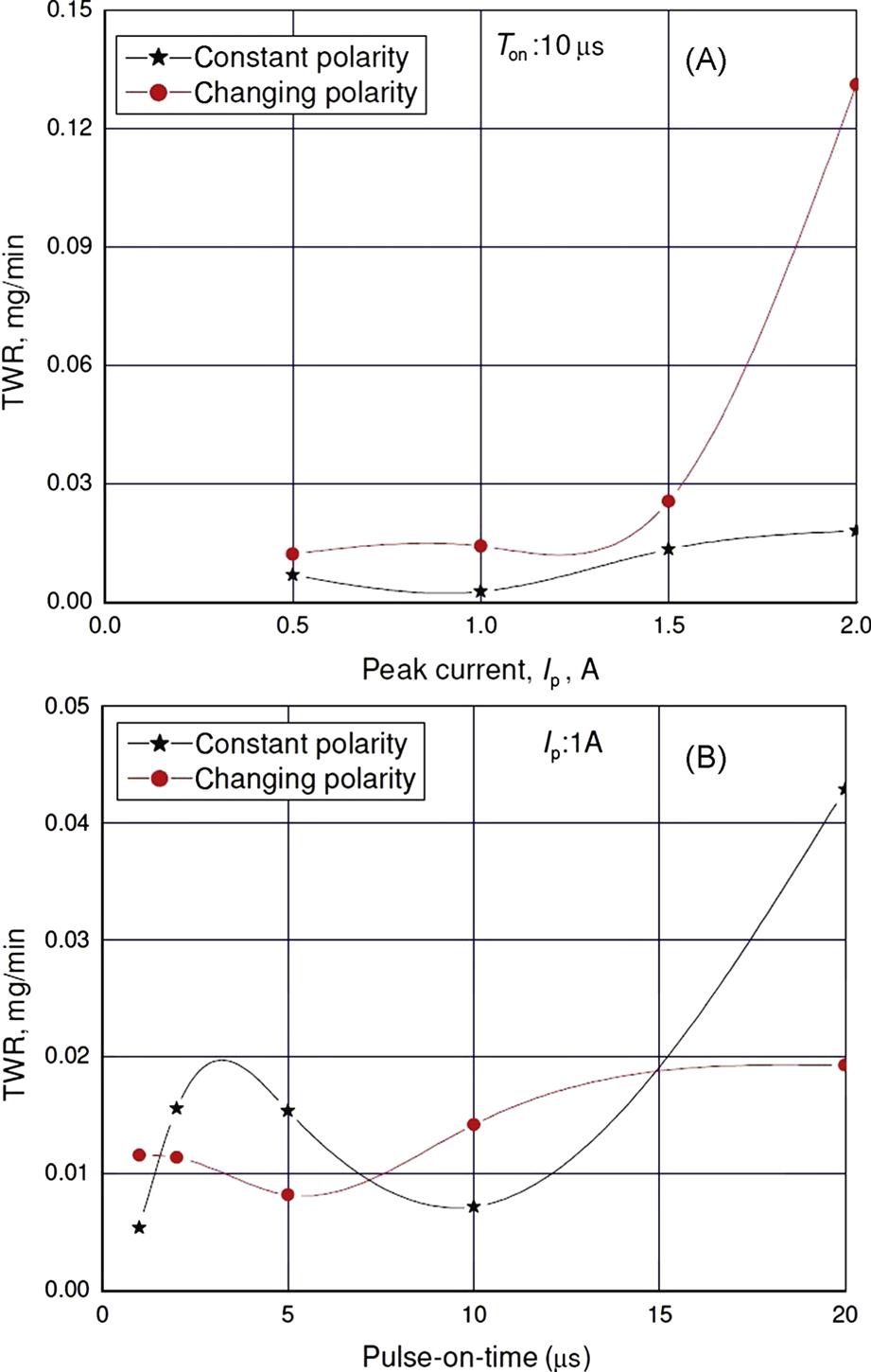
However, when pulse-on-time was varied while peak current, duty factor, and flushing pressure remained constant, as shown in Fig. 4.5B, TWR decreased significantly with changing polarity relative to constant polarity. This indicates that pulse-on-time is the more critical factor in tool wear than peak current. Therefore, for minimum TWR, it is better to use changing polarity with smaller pulse-on-time (1–10 μs) and low peak current of 1 A to yield a higher MRR and a low TWR. This observation reveals that shorter pulse-on-time, which means a higher frequency of sparking, and low peak current are suitable for micro-EDM.
Figs. 4.6A, B show the variation of OC with peak current and pulse-on-time, respectively. It is observed from Fig. 4.6A that OC decreases sharply from 0.5 to 1 A for both constant and changing polarity conditions and thereafter increases monotonically with an increasing peak current in both machining conditions. This observation clearly indicates that the optimum peak current setting is 1 A at the present process parameter range. If the peak current is low, the discharge energy is also low, which means longer machining time, exposing the sidewall of the hole to secondary sparking and thus resulting in larger OC. However, the increase in OC at a higher peak current is due to higher discharge energy and larger debris concentration in the gap because of higher MRR. Fig. 4.6B also indicates that OC increases steeply from 1 to 5 μs, decreases sharply from 5 to 10 μs, and again increases at 10–20 μs for constant polarity. Thus, OC fluctuates with the change in pulse-on-time for constant polarity. However, for changing polarity, OC is found to decrease gradually for pulse-on-time from 1 to 20 μs, suggesting that the changing polarity technique achieves a lower OC in the machining of microholes, hence increasing the geometrical accuracy of the machined microhole in Ti-6Al-4V. Further, throughout the range of pulse-on-time from 1 to 20 μs, the magnitude of OC is far lower with changing polarity than with constant polarity, which is an indicator in itself that changing polarity yields low OC and results in the improvement of microhole geometry. This effect is attributable to the fact that the carbon particles, which are by-products of micro-EDM, are deposited on the surface of the tool electrode, helps prevent secondary sparking. Thus, only the end face or bottom face is exposed for sparking, reducing OC and resulting in straight-through microhole generation, thus improving the accuracy of microhole machining.

It is observed from Figs. 4.7A, B that DVEE decreases sharply with the increase in peak current and pulse-on-time. The lowest DVEE is obtained at 1 A and 10 μs, as seen in the figures for both constant and changing polarity machining conditions. DVEE is also observed to be less with changing polarity than with constant polarity throughout the peak current and pulse-on-time ranges considered in the experiments. With the novel technique of changing the polarity, a straight microhole can be achieved. As the depth of the microhole increases, the sparking points shift radially inward. When the polarity is changed, the pointed tip of the microtool wears off uniformly, making the tool end broader and helping machine a straight microhole, thereby decreasing DVEE.

Optical micrographs of the microholes (entry and exit diameter) machined with constant and changing polarity at 1 A/10 μs/95% duty factor/0.5 kgf/cm2, and 1 A/20 μs /95% duty factor/0.5 kgf/cm2 are shown in Figs. 4.8A, B and 4.9A, B, respectively. The DVEE at a parametric combination of 1 A/10 μs/95% duty factor/0.5 kgf/cm2 for the constant polarity machining condition is 0.0270 mm, and for the changing polarity condition, the value is 0.0173 mm. The comparison of these data and the micrographs clearly indicate that DVEE and the geometrical shape are better when using the changing polarity condition for the micromachining of microholes by the micro-EDM. The SEM micrographs of machined microholes at the parametric settings of 1 A/10 μs/95% duty factor/0.5 kgf/cm2 and 1 A/20 μs/95% duty factor/0.5 kgf/cm2 with constant and changing polarity techniques are shown in Figs. 4.10A, B and 4.11A, B, respectively. These figures show that the thickness of recast layer formed on the microhole surface by using the polarity changing technique is less that that using the constant polarity technique, corroborating the fact that the surface quality of the machined microhole has improved with the new machining technique. This observation clearly indicates that with the changing polarity technique, a better machining condition is achieved during microhole machining by the micro-EDM process.


Thus, taking all aspects into account as discussed above and considering all major factors involved in micro-EDM machining, changing the polarity conditions and evaluating their effects extensively in this experimental investigation for determining the most effective parametric combinations, and exploring all possible aspects of choosing them, the following optimal parametric combinations have been selected. To achieve higher productivity, the optimal parametric combination with the changing polarity machining condition is 1 A/2 µs/0.5 kgf/cm2/95%. The optimal parametric combination with the changing polarity machining technique is 1 A/5 µs/0.5 kgf/cm2/95% for the least TWR and 1 A/20 µs/0.5 kgf/cm2/95% for the least OC. To achieve a higher dimensional accuracy, i.e., the least DVEE, the optimal parametric combination with the changing polarity machining technique is 1 A/10 µs/0.5 kgf/cm2/95%. One of these various optimal parametric combinations, depending on the immediate requirement, can be effectively utilized to achieve the same for the best possible machining conditions by using the polarity changing technique in an exponential time domain in order to improve the specific machining criteria in EDM during micromachining operations.
4.10.2 Rotating the microtool electrode
4.10.2.1 Experimental method and conditions
In this research investigation, the effects of peak current (Ip), pulse-on-time (Ton), and rotational speed of the microtool electrode are explored during microhole machining in micro-EDM. The experiments were conducted using the same ZNC R50 EDM machine to evaluate the effects of the rotation of electrodes with respect to MRR, TWR, OC, and DVEE on a Ti-6Al-4V workpiece of 1 mm thickness with a brass electrode 300 μm in diameter. During machining, kerosene is used as the dielectric fluid. To rotate the tool electrode, a tool rotational attachment has was used in which the rotational speed can be varied between 1–300 rpm at a resolution of 2 rpm. The ranges of peak current (Ip) and pulse-on-time (Ton) selected were 0.5–2 A and 1–20 μs, respectively. The experiments were conducted in two stages: (1) varying only peak current from 0.5 to 2 A keeping pulse-on-time, duty factor, and flushing pressure as constant at 10 μs, 95%, 0.5 kgf/cm2, respectively, and (2) varying only pulse-on-time from 1 to 20 μs, with peak current, duty factor, and flushing pressure constant at 1 A, 95%, and 0.5 kgf/cm2, respectively, with stationary and rotating electrodes with a rotational speed of 150 rpm in each case. The peak current was fixed at 1 A because for micromachining, very low current density is not sufficient to melt and vaporize the workpiece, and very high current density leads to higher TWR and larger thermal damage of the workpiece surface. On the other hand, pulse-on-time is fixed at 10 μs because short duration helps reduce tool wear, thus being more beneficial for micromachining. A moderate rotational speed of the electrode was selected, i.e., 150 rpm after conducting trials as this speed facilitates the removal of debris from the machining zone, thereby keeping tool wear at a minimum.
4.10.2.2 Experimental results and analysis
By using the microtool electrode rotating facility with a developed tool holder, the experiments were conducted to evaluate the effects of micro-EDM parameters on process criteria, namely, MRR, TWR, OC, and diametral variation at entry and exit (DVEE) of the machined microholes.
The variations of MRR with peak current (Ip) and pulse-on-time (Ton) with stationary and rotating electrode are shown in Figs. 4.12A, B, respectively. The graph indicates that MRR increases with an increase in peak current as was expected for both stationary and rotating electrodes. MRR increases because higher peak current leads to higher discharge energy. The same figure shows that with a rotating electrode, a higher MRR is obtained. The higher MRR with a rotating electrode may be attributed to better removal of sludge and carbonized particles from the machining zone because of the centrifugal force of rotation. This improved sludge removal due to the rotating effect of the electrode helps expose the actual machining surface, which then improves the overall machining condition, leading to a higher MRR. Thus, for maximum MRR from within the considered range of parametric setting, the best parametric combination in the present case study is 2 A/10 μs/0.5 kgf/cm2/95% /150 rpm.

Figs. 4.13A, B, respectively, show the variations of TWR with peak current (Ip) and pulse-on-time (Ton) with stationary and rotating electrode. It can be observed from the graph that TWR increases as the peak current increases from 0.5 to 1.5 A. However, TWR is observed to decrease from 1.5 to 2 A. The increase in TWR with the increase in peak current can be attributed to the increase in discharge energy and the rotational effect of the electrode. A further increase in peak current increases machining efficiency and decreases tool wear because the tool electrode is subjected to high-energy electric field for a shorter duration. Thus, this figure clearly indicates that for microhole machining with low TWR, a smaller peak current is suitable. Owing to a rotational effect, the magnitude of TWR further decreases, which is evident from the figure under consideration. This may be attributed to enhanced removal of debris caused by the tangential force of rotation. Thus, for least TWR, the best parametric combination from within the considered range of parametric settings is 1 A/10 μs/0.5 kgf/cm2/95%/150 rpm.

Figs. 4.14A, 4.14B respectively show the variations of OC with peak current (Ip) and pulse-on-time (Ton) with stationary and rotating electrodes. It is observed from the figure that OC decreases with an increase in peak current ranging from 0.5 to 1 A, which may be attributed to the increase in discharge energy with the increase in peak current and enabling faster machining, thereby reducing the effective machining time. The reduction in machining time means less exposure of the tool electrode to discharge energy, which is responsible for tool wear. However, with peak current beyond 1 A, OC increases monotonically. An increase in peak current above 1 A leads to larger discharge energy, causing a larger MRR and resulting in a larger OC. Thus, the most suitable parametric combination for the least OC from within the considered range of parametric settings is 1 A/10 μs/95% duty factor/0.5 kgf/cm2/150 rpm.

The variations of DVEE with peak current (Ip) and pulse-on-time (Ton) with stationary and rotating electrodes are shown in Figs. 4.15A, B, respectively. The same graph shows that with the increase in peak current, DVEE decreases. Furthermore, the magnitude of DVEE with a rotating electrode is less than that with a stationary electrode throughout the considered range of peak current. As the depth of the microhole increases, the sparking point shifts radially inward. When the peak current is increased, the thermal energy density increases at the pointed tip of the microtools. This high density discharge energy rapidly melts and vaporizes the sharp microtool tips, subsequently broadening the microtool end, which finally helps achieve a straight-through microhole by decreasing DVEE. Further, the rotational speed of the tool helps remove the sludge and debris efficiently from the machining zone and reduces the chances of secondary discharge sparking, thereby providing stable machining conditions for achieving microhole with less DVEE. The lowest DVEE achieved is with the parametric combination of 2 A/10 μs/95%/0.5 kgf/cm2/150 rpm.
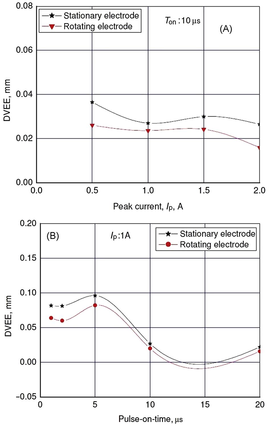
The improvement in microhole geometry with the increase in peak current coupled with rotation of the tool electrode may be attributed to better flushing of debris due to rotation of electrode, uniform tool wear, and evenly distribution of discharge energy.
Fig. 4.16A shows the optical micrographs of the microhole diameters at the entry and exit machined with the parametric setting of 1 A/5 μs/95% duty factor/0.5 kgf/cm2, i.e., with the stationary microtool. Fig. 4.16B shows the optical micrographs of the microhole diameters at entry and exit machined with the parametric setting of 1 A/5 μs/95% duty factor/0.5 kgf/cm2/150 rpm, i.e., with the rotating microtool. It can be observed from these two micrographs that with the rotating tool electrode, straight-through microhole can be fabricated.

4.10.3 Comparative study of using kerosene and deionized water dielectrics
4.10.3.1 Experimental method and conditions
The use of various dielectrics (hydrocarbon oil, deionized water, EDM oil, etc.) has important effects for improvement of machining performance. Different dielectrics have different properties in terms of dielectric strength, degree of recovery capability, degree of fluidity, and chemical compositions. Therefore, it is very important to carry out extensive research for employing various type of dielectric fluid during micro-EDM of Ti-6Al-4V. In this research, a comparative study was performed for using pure kerosene and deionized water on micro-EDM performance criteria, i.e., MRR, TWR, OC, and DVEE. The same EDM system mentioned earlier is used for this experimental investigation. When deionized water is employed for machining of microhole, a separate dielectric circulating system was used as the micro-EDM system uses kerosene-based dielectric. The circulating system consists of a pump, a reservoir, piping, a pressure-regulator, and a filter. Ti-6Al-4V plates of size 13×15×1 mm are used to machine through microholes. Tungsten microtool electrodes of diameter 300 μm were used in this experiment. Peak current (Ip) (0.5, 1, 1.5, 2 A) and pulse-on-time (Ton) (1, 2, 5, 10, 20 µs) were varied in this study, with other process parameters such as flushing pressure (0.5 kgf/cm2) duty factor (95%) remaining constant. Performance criteria such as MRR, TWR, OC, and DVEE were measured after each experiment. Comparative investigation and analysis was performed to study the influence of dielectric liquid on machining performances.
4.10.3.2 Experimental results and analysis
Fig. 4.17 shows the comparative plot of MRR using kerosene and deionized water with varying peak current and pulse-on-time. The figure shows that the MRR is employing more deionized water than kerosene at all values of pulse duration. Kerosene is a chemical compound of carbon and hydrogen and that during machining in micro-EDM, it decomposes at a discharge temperature and produces a titanium carbide (TiC) layer on the machined surface. On the other hand, at high temperature discharge, deionized water decomposes and produces a titanium oxide (TiO2) layer on the machined surface. The melting point of TiC is higher (3150°C) than that of TiO2 (1750°C). Thus, large discharge energy is required for improving the MRR using kerosene. In addition, the size of the craters produced on the machined surface that employs kerosene dielectric is less that using deionized water, thereby improving the MRR.

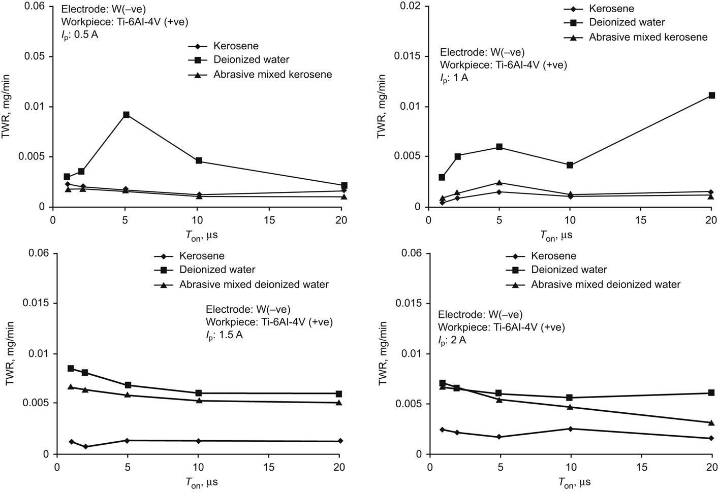
Fig. 4.18 show the comparative plot of TWR using two different dielectrics varying peak current and pulse-on-time. The figure reveals that higher TWR is obtained using deionized water than machining with kerosene. Kerosene decomposes in high discharge energy and produces carbon particles. These particles adhere to the microtool electrode surface and further restricts rapid wear of the tool. On the other hand, deionized water does not produce any carbon particle; consequently, TWR is higher enough by using deionized water.
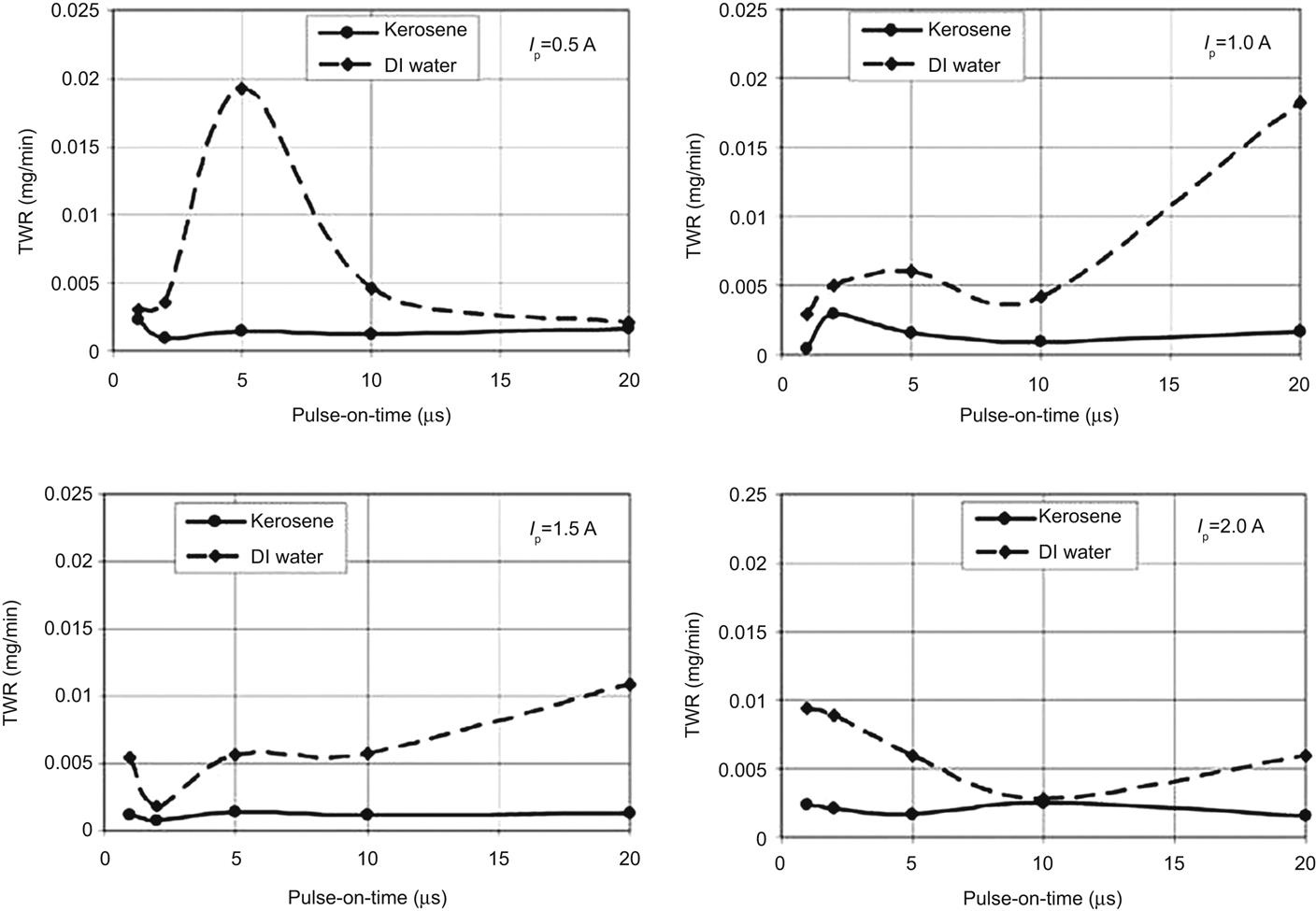
Fig. 4.19 show the comparative plot of OC with varying peak current and pulse-on-time using kerosene and deionized water. The plot shows that the OC of the machined microholes is larger when using deionized water at pulse durations of 1 and 2 µs. However, at higher pulse durations, the OC is larger when using kerosene. Deionized water releases oxygen during discharge and influences machining stability and increases the possibility of a crater formation. When these debris particles try to eject out through a small gap of tool surface and microhole walls, secondary sparking occurs, resulting in higher OC. However, at a higher pulse duration, machining stability and efficiency increase because of more pulses per second, resulting in a higher OC with kerosene. High peak current results in a higher OC using deionized water compared with kerosene.

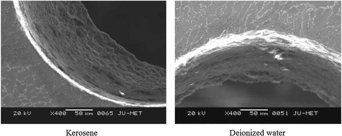
Fig. 4.20 shows the comparative results of the diametral variance at entry and exit using kerosene and deionized water with varying peak current and pulse-on-time parameters. The figure shows that the DVEE of the microholes increases at low discharge duration when deionized water is used. However, a further increase in pulse duration results in a decrease in DVEE when deionized water is used. The least DVEE is obtained at a pulse duration of 5 µs and peak current of 1.5 A. On the other hand, by employing deionized water, the DVEE is reduced at peak currents of 0.5 and 1 A. As the peak current increases, the diameter variance also increases. Thus, a straight-through microhole is difficult to achieve. SEM micrographs of machined microholes using pure dielectrics are shown in Fig. 4.21. These figures confirm that kerosene dielectric produces microholes with higher accuracy than does deionized water. Fig. 4.22 shows the inner surface topography of the machined microholes for both dielectrics at 2 A/10 µs parametric combination. The figure shows a smoother inner microhole surface when pure deionized water rather than pure kerosene is used. In Fig. 4.23, the SEM micrographs of the microhole edges are shown to examine the white/recast layer formation using kerosene and deionized water. The thickness of the white layer is much lower when deionized water rather than kerosene is used. Moreover, with an increase in the pulse-on-time, the thickness of the white layer increases. As pulse duration increases, the effective machining time also increases. Therefore, more debris is generated, and this debris adheres to the microhole surface and is resolidified as deionized water, which has a higher cooling rate than kerosene.


4.10.4 Comparative study of mixing a boron carbide additive in dielectrics
4.10.4.1 Experimental method and conditions
In micro-EDM, debris in the IEG facilitates the ignition process and further increases the gap size and overall flushing conditions (Luo, 1997). The absence of debris particles in the gap can result in arcing between the electrodes and further leads to a lack of precise feeding mechanism. However, excess debris leads to uneven discharge and short-circuiting. Some debris particles in the machining gap provide increased discharge transitivity, gap size, breakdown strength, and deionization (Jeswani, 1981). Past studies were performed on EDM by employing powder-mixed dielectrics. However, no research reportedly uses powder-mixed dielectric during micro-EDM of Ti-6Al-4V. In the present study, boron carbide (B4C) powder is mixed (size 8–10 μm and of concentration 4 g/L) in both dielectrics to investigate the different micro-EDM response criteria. B4C powder exhibits high chemical resistance and hardness, excellent wear, and abrasion resistance, among others. These properties may provide effective and efficient discharge conditions at the machining zone and enhanced machining performances. Ti-6Al-4V plates measuring 13×15×1 mm were used as workpieces, and a cylindrical tungsten microtool with a diameter 300 μm was used for microhole machining. MRR, TWR, OC, and diametral variance at entry and exit holes were measured after each experiment.
4.10.4.2 Experimental results and analysis
Fig. 4.24 shows comparative plots of MRR using pure kerosene, pure deionized water, and boron carbide (B4C) mixed dielectrics at different pulses-on-time and peak currents. MRR is high when deionized water rather than kerosene is used for all values of pulse duration and peak current. Again, in the case of B4C powder additives in kerosene, MRR increases with an increase in pulse duration at peak currents of 1.5 and 2 A. Moreover, MRR is larger using powder-mixed dielectrics compared with machining with pure dielectrics at higher values of pulse duration. Due to longer effective machining time per pulse, the increase of MRR with pulse duration is revealed using B4C mixed kerosene. The presence of boron carbide additive in kerosene further helps in the uniform distribution of discharge energy and better conduction of discharge current thereby enabling better machining condition. In case of B4C powder mixed in deionized water, MRR is more than pure deionized water at peak currents of 1.5 and 2 A. Therefore, the addition of carbide powder particles in dielectrics prevails better machining efficiency because to uniform distribution of discharge energy in the machining zone.

In Fig. 4.25, comparative results of TWR with pulse duration at various peak currents are shown. At peak currents of 0.5 and 1 A, TWR is less when B4C mixed kerosene rather than pure kerosene is used. Boron carbide abrasive mixed kerosene results in less tool wear. TWR is lower at a peak current of 1 A than at 0.5 A when additive mixed kerosene is used because higher discharge energy generates more carbon to adhere onto the microtool surface, thereby preventing secondary sparking. Powder mixed deionized water results in lower TWR at 2 A than at 1.5 A because more carbon particles are deposited on the microtool.
The comparative plots of the OC of microholes are shown in Fig. 4.26 at various pulse durations and different peak currents. The OC of the machined microholes is less when deionized water is used at peak currents of 0.5 and 1 A. However, at peak currents of 1.5 and 2 A, the OC is greater when deionized water rather than pure kerosene is used. In addition, OC is found to be large when powder-mixed dielectrics rather than pure dielectrics are used. The reason is that the suspended additive particles remove the molten layer from the machining zone and further reduce the formation of a thick white layer. OC decreases with an increase in pulse duration by using B4C suspended kerosene. However, a larger OC is found in B4C mixed deionized water.

In Fig. 4.27, comparative plots of DVEE are shown for varying peak currents and pulse-on-time parameters. The DVEE of the microholes employing deionized water is lower than that of the microholes employing kerosene at peak currents of 0.5 and 1 A. However, at peak currents of 1.5 and 2 A, DVEE is larger when deionized water is used. Boron carbide powder-mixed kerosene results in large DVEE compared with pure kerosene at low peak currents of 0.5 and 1 A. As machining progresses, the additive boron carbide particles create more carbon adhesion on the work surface, further resulting in reduced material removal at the exit side of the microhole and increased variance at entry and exit diameters. However, at higher peak currents of 1.5 and 2 A, using powder particles help in the uniform distribution of discharge energy, which, in turn, leads to a higher dimensional accuracy of the microholes compared with that obtained when pure deionized water is used.
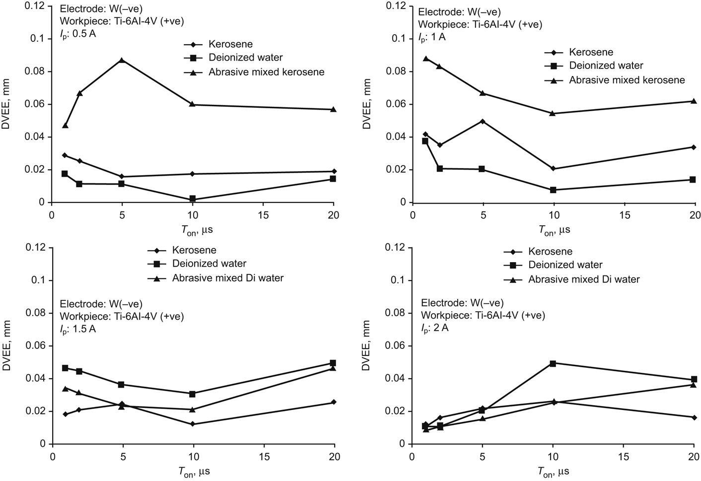
Fig. 4.28 shows the SEM micrographs of the inner surface of a machined microhole using powder-mixed kerosene and deionized water at parametric combinations of 1 A/5 μs and 2 A/10 μs of peak current and pulse-on-time. The micrographs reveal that with more discharge energy, an inaccurate microhole is generated using powder mixed deionized water, resulting from more secondary sparking phenomena. However, a smooth inner surface is produced using powder-mixed deionized water rather than powder-mixed kerosene. In Fig. 4.29, the SEM micrographs of a microhole’s edge are viewed to examine the recast/white layer formation during microhole machining. It is revealed from these figures that the recast layer formed on the edges is much less than that produced using pure dielectrics. The reason is that the additive particles help remove the molten debris and restrict the formation of a thick white layer on the machined microhole edges.


Conclusions
The present chapter describes the overview of the micro-EDM process starting with the EDM principle and then briefly describes the micro-EDM process, its system components, significant process parameters, and the micro-EDM process performances. A brief literature review of the micro-EDM process of micromachining of Ti-6Al-4V materials is presented. Experimentation and analysis of microhole machining in micro-EDM are carried out, implementing four machining strategies, such as (1) changing the polarity of tool electrode and workpiece, (2) rotating the microtool electrode, (3) employing kerosene and deionized water as dielectrics as well as a comparative study of the process criteria, and (4) employing boron carbide additive in kerosene and deionized water and use it as dielectrics. These four sets of experimental investigation and analysis reveal that these novel machining strategies during microhole machining in micro-EDM in Ti-6Al-4V has significant influences on the performance criteria, such as MRR, TWR, OC, and diametral variance of the entry and exit of the microhole. A straight-through microhole can be generated by properly controlling the significant process parameters such as peak current, pulse-on-time, and flushing pressure. The micro-EDM process has great versatility and therefore has huge potential for fabricating various microstructures as well as microsystems and devices in a wide range of hard-to-machine materials. Micro-EDM is a slow process; thus, the novel machining strategies mentioned above must be implemented to improve the process performances, thereby improving the accuracy of the microstructure, surface finish, and efficiency. Furthermore, innovative hybrid micromachining processes can also be developed for micro-EDM to machine Ti-6Al-4V alloy in order to increase the yield of micromanufacturing.
Acknowledgements
The authors acknowledge the financial support and assistance provided by CAS Ph-IV programme of Production Engineering Department of Jadavpur University, Kolkata under University Grants Commission (UGC), New Delhi, India.