
Microelectrochemical machining
Principle and capabilities
Z. Liu, C. Gao and J. Zhao, Nanjing University of Aeronautics and Astronautics, Nanjing, Jiangsu, China
Abstract
Electrochemical machining (ECM) has been widely used in manufacturing owing to its capability of machining hard metals in the absence of mechanical stress, heat-affected zone, and tool wear. Allowance in microelectrochemical (micro-ECM) machining can be removed in electrochemical drilling, milling, or cutting through a relative movement between a workpiece and a universal electrode tool. The purpose of this chapter is to review the state-of-the-art development and capabilities of micro-ECM technology. Some key fundamentals of microelectrochemical machining, e.g., principle, utilization of ultra-short pulses, and miniaturization of cathode, have been briefly introduced in Section One. Section Two demonstrates a variety of micro-ECM approaches, which involve micro-ECM drilling, micro- ECM milling, through-mask micro-ECM, microwire electrochemical cutting, and electrochemical jet machining. Section Three presents several hybrid machining processes combined with micro-ECM, which have been the research interest over the last decade.
Keywords
Electrochemical machining; microelectrochemical machining; microtool; ultra-short pulses ECM; hybrid machining; micro-ECM drilling; micro-ECM milling; micro-ECM cutting
5.1 Fundamentals of microelectrochemical machining
5.1.1 Principle of electrochemical machining
Electrochemical machining (ECM) is a nonconventional manufacturing process used as an alternative to conventional mechanical machining processes for difficult-to-cut metals. The advantages of ECM includes tool electrode wear-free, residual stress-free, absence of heat-affected zone, and recast layer. The ECM process was first patented by Gusseff in 1929. Significant advances during the 1950s and the 1960s developed ECM into a major technology in the aircraft and aerospace industries for shaping, finishing, deburring, and milling operations of large parts (Bhattacharyya, Munda, & Malapati, 2004; McGeough, 1974; Rajurkar, Zhu, McGeough, Kozak, & De Silva, 1999). At present, the ECM process plays an important role in the manufacture of a variety of parts, ranging from machining large, complex-shaped metallic pieces to fabricating microscaled parts that are a few micrometers in size. Many industries, such as aerospace, automotive, and electronics, apply the ECM process in the mass production of turbine blades, die and mold, shaving heads, artillery projectiles, and surgical implants (Kozak, Rajurkar, & Makkar, 2004; Rajurkar et al., 1999).
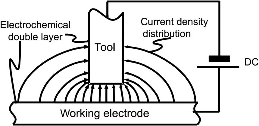
During the ECM process, both the anode (workpiece) and the cathode (tool electrode) are submerged in a constantly renewed electrolytic solution, and a voltage is applied. A distance between the anode workpiece and the cathode tool—i.e., the machining gap—must be maintained so that current passes through the gap and a chemical reaction occurs. Such a situation is sketched in Fig. 5.1. As a result, the anodic material is corroded, and the workpiece is shaped according to the geometrical features of the cathode (McGeough, 1974). The metal removal from the anode material produces an increase in the gap distance, which causes a decrease in the current; therefore, either the anodic workpiece or the cathodic tool is moved by a mechanical feed drive system to maintain the desired gap distance.
Since current passes across the machining gap by the ions of the electrolyte during ECM, a solution of high conductivity is used as the electrolyte, e.g., a 5–25 wt% aqueous solution of sodium chloride (NaCl). Certain acid solutions, such as HCl and H2SO4, have also been used as electrolytes, specifically for some situations where electrolyte cannot be easily renewed in the gap region. Generally, the most practical electrolytes are solutions of neutral salts— e.g., NaCl, KCl, and NaNO3. With ECM of the steel workpiece in a NaCl solution as an example, the chemical reaction that occurs at the anode (workpiece) is
(5.1)
and at the cathode (tool electrode) is
(5.2)
Metals such as tungsten and molybdenum can be machined only in alkaline electrolyte because highly protective films are formed on W or Mo anodes in neutral solutions.
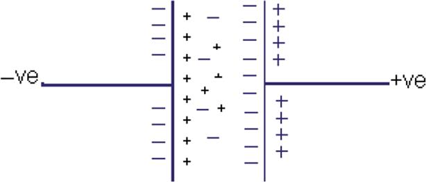
Theoretically, it is the potential drop across the double layer (DL), which is a common term to describe the electrode/electrolyte interface (shown in Fig. 5.2), drives the electrochemical reactions in ECM (Park, Kim, & Chu, 2006). The DL influences the electron transfer rate across the interface of the electrodes, thereby affecting the electrochemical reaction rate of an ECM cell. The DL structure and its capability of transferring ions depend on parameters such as the electrode material, electrode porosity, type of electrolyte, extent of specific adsorption of ions and molecules, and temperature (McGeough, 1974).
5.1.2 Microelectrochemical machining using ultra-short pulsed current
ECM has received much attention in the fabrication of microparts since the 1980s (Bhattacharyya & Munda, 2003; Datta, Shenoy, & Rominkiw, 1996). However, it was not until end of the last century that the micro-ECM research accessed a prominent breakthrough by introducing ultra-short pulses current into the process, which leads to a strong confinement of electrochemical reactions down to nanometer precision to achieve high resolution (Kirchner, Cagnon, Schuster, & Ertl, 2001; Rajurkar et al., 2006; Schuster, Kirchner, Allongue, & Ertl, 2000). Pulsed current enables recovery of the gap conditions during pulse-off times, giving improved dissolution efficiency. It also shows a more flexible control than traditional ECM by varying the pulse duration and pulse-duty factor to optimize the removal rate and the surface finish.
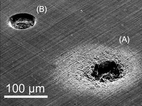
The DL can be commonly characterized as a capacitance during ECM using an ultra-short pulsed voltage (Kirchner et al., 2001; Park et al., 2006; Rajurkar et al., 2006; Schuster et al., 2000). The DL is periodically charged and discharged on both electrodes during pulse duration. The charging time constant (τ) is a product of the DL capacitance (c) and the resistance of the electrolyte along the current path (ρ), i.e., τ=ρc. This resistance locally varies depending on the local separation of the electrode surfaces. Upon proper pulse duration, the DL areas where the electrodes are in close proximity are strongly charged by the voltage pulses, whereas, at farther distances the charging becomes progressively weaker. The rates of electrochemical reactions are exponentially dependent on the potential drop in the DL. Thus, chemical reactions are strongly confined to the polarized electrode regions in close proximity. In other words, if the duration of applied pulses is longer than the time constant (τ), the DL becomes charged high enough for dissolution. However, in other regions where the time constant (τ) is larger than the pulse duration, the DL is not charged sufficiently for dissolution. Fig. 5.3 shows a comparable results machined by ECM using pulses voltage with different pulse durations.
The abovementioned explanation can very well describe the localization principle of ultra-short pulsed micro-ECM; however, some researchers argued that inductance effects cannot be disregarded in an actual micro-ECM system because of very high pulse frequency (Park et al., 2006). They developed an equivalent electrochemical cell model considering inductance (L), as illustrated in Fig. 5.4. Resistance (R) from electrolyte resistivity is determined by the current flow path between two electrodes. Capacitance (C) is the product of the specific DL capacitance and the whole area immersed in an electrolyte. The model separated all current flow through an electrochemical cell into a faradaic current, i.e., a reaction current and a transient current, i.e., nonfaradaic current (Bard & Faulkner, 2001). Faradaic current represents the material dissolution rate and nonfaradaic current only charges and discharges the DL capacitance. When ultra-short voltage pulses are applied, nonfaradaic current dominates transiently, and dissolution is affected by the cell impedance, which is the sum of resistance and capacitive reactance.

5.1.3 Miniaturization of cathode tool
The ECM is a manufacturing process in which a certain rate of anodic dissolution is maintained by feeding a preshaped tool towards the workpiece with a constant feed rate. Consequently, the workpiece surface will be shaped according to the geometrical features of the tool electrode, which is commonly macrosized. Principally, a micro-ECM cell also needs a preshaped microsized cathode to produce microstructures in the process. However, the introduction of ultra-short pulsed current in the micro-ECM process can significantly improve the metal dissolution localization to submicrometer regions; therefore, relatively simple-shaped micro tools—e.g., a cylindrical rod—can be applied to fabricate complex structures. In most cases, the size of the tool electrode determines the size of structures machined in micro-ECM (Brousseau, Dimov, & Pham, 2010; Liu, Zeng, & Zhang, 2014; Mathew & Sundaram, 2012).
Many technologies can be used for fabricating micrometer-scale tools—tools for micromechanical machining, electro-discharge machining (EDM), electrochemical etching, electrochemical manufacturing, and so on. Micromechanical machining is a process employing a microcutter to mechanically remove the material from the workpiece. Basically, the hardness of the cutter needs to be higher than that of the workpiece. EDM is an approach using repeated thermal discharge to erode metals by pulsed voltage applied between two electrodes. The process can be used to fabricate microtools with the advantages of noncontact between electrodes and high feasibility regardless of hardness and stiffness of the workpiece. Electrochemical etching, which is similar to ECM, is a method that relies on an acidic or alkaline solution to dissolve unwanted metals from the workpiece.
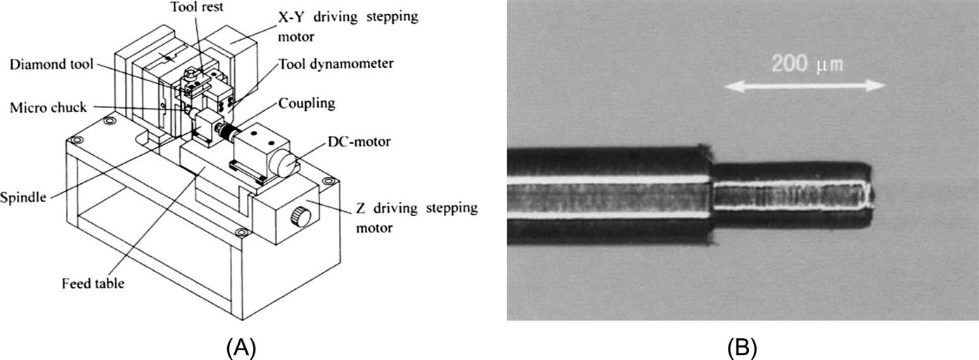
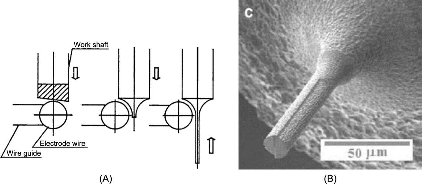
The literature reported some applications of fabricating a micrometallic tool by using variant approaches. As shown in Fig. 5.5, Lu & Yoneyama (1999) used a microdiamond single-point cutter to turn a workpiece into one with a diameter of 10 μm and a rotation speed of up to 15,000 rpm in a microlathe system. On the basis of the EDM technology, Masuzawa, Fujino, Kobayashi, Suzuki, and Kinoshita (1985) proposed the wire electro-discharge grinding (WEDG) method to prepare very thin rods sized to a few tens of micrometers in diameter. Ali and Ong (2006) applied the WEDG process to fabricate microtools 20 μm in diameter in tungsten carbide, as demonstrated in Fig. 5.6. Lim, Wong, Rahman, and Lee (2003) fabricated microelectrodes of 100 μm in diameter with high aspect ratios by using micro-EDM, which is classified into three types of sacrificial electrode: stational sacrifical block, rotating sacrifical disk, and guided running wire (Fig. 5.7).
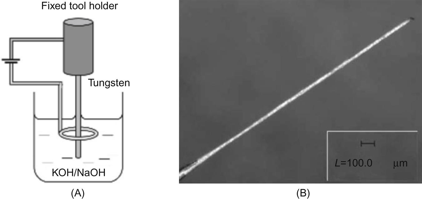
Electrochemical etching is originally considered a fast and affordable method for fabricating metallic tips for scanning tunneling microscopy or atom probe field ion microscopy. The standard method involves dipping a tungsten wire into an electrolyte; etching then begins at the air/electrolyte reaction interface and continues into the immersed metallic wire (Duong & Kim, 2015; Fan, Hourng, & Wang, 2010), as shown in Fig. 5.8. Wang and Zhu (2009) introduced a two-step composite processing technology, combining EDM and electrochemical etching, to fabricate microelectrode array. Rectangular columns are machined by wire electrical discharge machining (WEDM) at the first stage; afterwards, electrochemical etching is used to erode the microelectrode array into cylindrical columns (shown in Fig. 5.9).

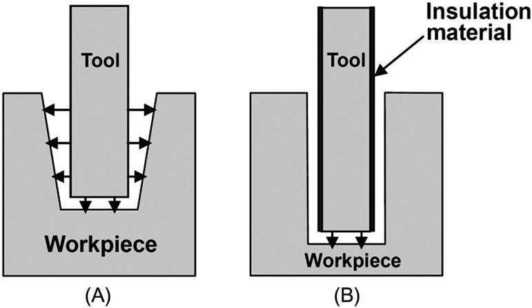
During the micro-ECM process, since electrolysis takes place as long as the current flows through the tool, using an uninsulated tool results in producing a taper shape at the machined side wall, as demonstrated in Fig. 5.10A. Coating an insulation layer at the sides of the tool aids the micro-ECM process to restrict current flows to an uninsulated area and consequently reduce stray corrosion effectively (Liu, Liu, Qiu, & Qu, 2009; Park et al., 2006). Therefore, in order to reduce the taper, it is necessary to insulate the sides of the tool, as shown in Fig. 5.10B. As a result, the machining gap is uniform regardless of the machining depth, and the taper shape of structures can be markedly prevented.
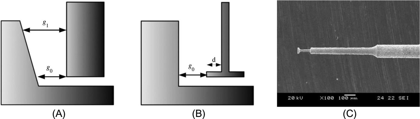
Compared with the cylindrical electrode, a disk-type electrode is also capable of reducing taper on the side wall profile during the process, as demonstrated in Fig. 5.11 (Kim, Ryu, Choi, & Chu, 2005). For a cylindrical electrode (Fig. 5.11A), the upper side of a wall is dissolved more than the bottom side during downward feeding of the tool. However, by applying a disk-type electrode (Fig. 5.11B), dissolution can be restricted to the disk region with less dissolution to the side wall, especially in the case of using a passive electrolyte such as NaNO3.
5.2 Variety of micro-ECM processes
5.2.1 Microelectrochemical drilling
Microelectrochemical drilling (ECD) is a process to machine microholes, applying a shaped tube or a cylindrical cathode tool feeding axially toward the workpiece. A number of microdrilling applications have been developed in aviation, space, automobile, electronics and computer, as well as medical and optics manufacturing in extremely hard metallic materials. Sen and Shan (2005) summarized electrochemical micro- and small drilling processes into shaped tube electrolytic machining (STEM), capillary drilling (CD), electro-stream drilling (ESD), and jet electrolytic drilling (JED), as illustrated in Fig. 5.12. They pointed out that most of the abovementioned processes use a weak acidic solution as the electrolyte, resulting in the dissolution of material in metal ions, which can be easily carried away from the machining region, and achieving smooth and deep holes of high aspect ratio. The achievable minimum hole size by the STEM, CD, ESD, and JED were ø0.5, ø0.2, ø0.1, and 0.125 mm, and the typical aspect ratios of that could be approximately 16:1 for these four measures.

Park et al. (2006) studied the effect of the tool electrode size on micro-ECM drilling using a 0.1 M sulfuric acid as electrolyte, a cylindrical microtool electrode insulated on the side surface, and an ultra-pulsed power source. As shown in Fig. 5.13, they found that an insulated tool electrode was capable of increasing machining depth and effectively preventing the taper at the side of the machined hole. Yang, Park, and Chu (2009) investigated the characteristics of the ECD process, applying ultra-short pulsed current, a semi-cylindrical tool with a rotation rate of 9.7 rpm, and an ultrasonic vibration on the tool. They concluded that ECD with a semi-cylindrical tool combined ultrasonic vibrations that provided increased flow space for the electrolyte, which results in a higher aspect ratio compared with the process in the absence of vibrations (Fig. 5.14). Ultrasonic vibrations improved electrolyte diffusion and convection, as well as bubble elimination, and a considerable amount of machining time was saved. Liu, Qiu, Heng, and Qu (2009) presented a micro-ECD method of periodically retracting a tool electrode during the process. With the high-velocity retraction of the tool electrode, the machining region can be flushed using a fresh electrolyte, and corrosion sludge can be carried away periodically during the process. Consequently, the machining stability and localization can be improved.

5.2.2 Microelectrochemical milling
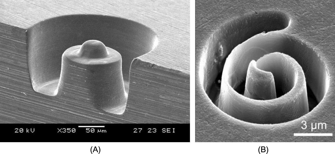
In the milling mode, a simple cylindrical tool typically has a diameter ranging between few tens to two hundred microns and is used to make a variety of structures. True three-dimensional contouring is possible by a proper tool position control (Rajurkar et al., 2006). During the ECM milling, the tool electrode moves along a path in a layer-by-layer fashion to achieve the desired geometry. On the one hand, the use of cylindrical tool avoids complex and time-consuming electrode design and fabrication; on the other hand, the up-to-date micromachining technologies cannot easily produce a complex preshaped tool electrode of a micrometer-scale without entailing efficiency and high costs. As a result, micro-ECM milling using a cylindrical tool is a particularly suitable approach for machining complex 3D microstructures. For example, Kim et al. (2005) fabricated various 3D microstructures through the electrochemical milling process. With a dilute electrolyte (0.1 M H2SO4) and an ultra-short pulsed voltage (6.0 V, 60 ns duration and 1 μs period), microstructures with good surface quality (Ra 0.28 μm) were made using layer-by-layer machining. Fig. 5.15A shows a microhemisphere on the top of a cylinder. Fig. 5.15B demonstrates a spiral machined into a Ni sheet with 3 ns pulses.
5.2.3 Through-mask microelectrochemical machining
The through-mask ECM, capable of patterning thin films or foils by wet etching, generally involves selective material removal through photoresist masks. Compared with the common chemical etching process, the through-mask ECM method offers better control and flexibility for microfabrication. Other advantages include higher machining rate, use of nontoxic electrolyte, and possibility of machining a wide range of electrically conductive materials (Datta, 1997). Through-mask micro-ECM process is receiving considerable attention in the electronics and other high-tech industries because of high throughput for making mass microstructures. A standard through-mask micro-ECM begins by bonding a sheet of inert photoresist on the metal anode workpiece. Lithography, which includes procedures of spin coating, prebaking, exposure, development, and postbaking, are employed to pattern the photoresist. The photoresist is only a one-time mask and must be peeled off from the anode workpiece after machining (Datta & Landolt, 2000).
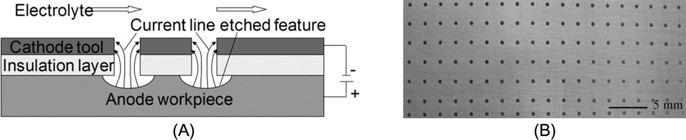
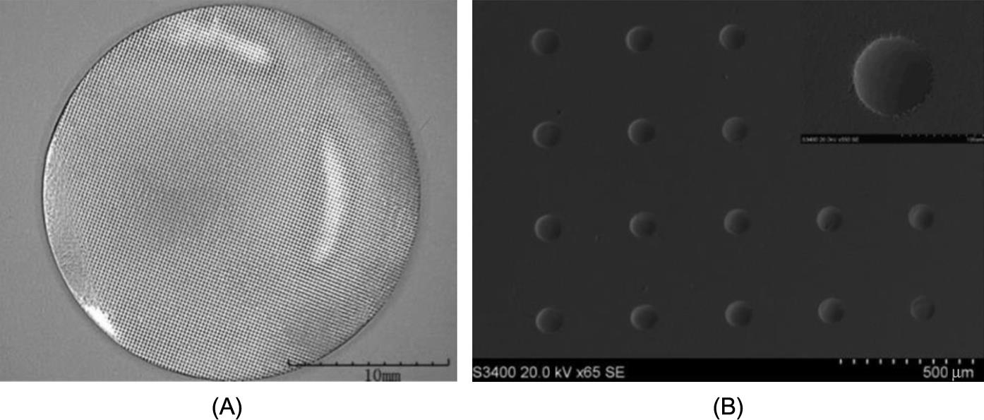
Zhu, Qu, Li, and Zeng (2009) demonstrated a modified through-mask micro-ECM process, as shown in Fig. 5.16, in which a mask with a patterned insulation plate coated with metal film as cathode is closely attached to a workpiece plate instead of bonding a photoresist layer on the workpiece in the standard through-mask micro-ECM. Compared with the standard through-mask micro-ECM, the modified process offers advantages, such as short lead time and low cost because the mask could be re-used. Fig. 5.17 shows a machining result achieved using a movable dry-film mask micro-ECM process (Qu, Zhang, & Chen, 2015). The process utilizes a microscale pattern transfer without photolithography of substrates to reduce the ratio of etched profile diameter and micropattern diameter. The electrochemical tool carrying the dry-film mask remains in close contact with the anodic workpiece surface during the machining process.
5.2.4 Microwire electrochemical machining
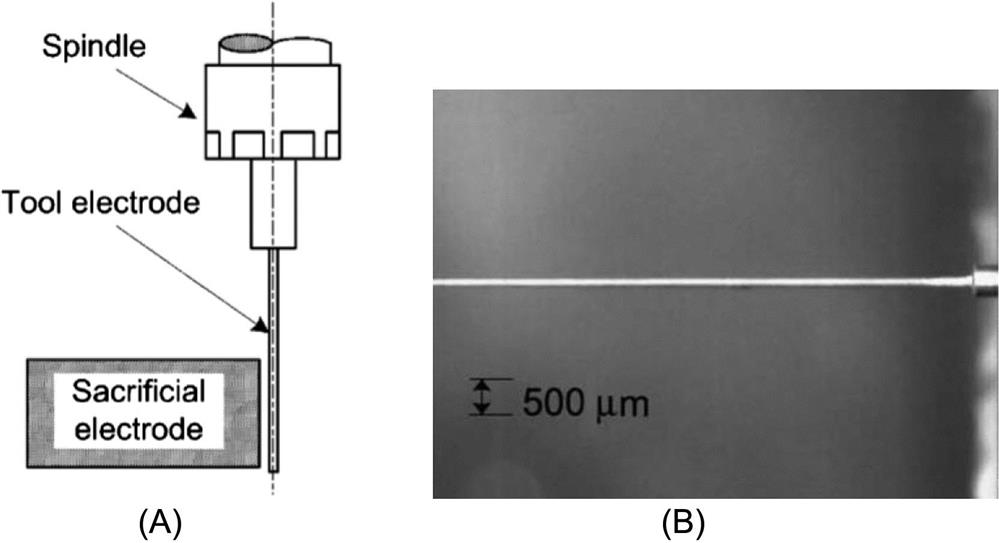
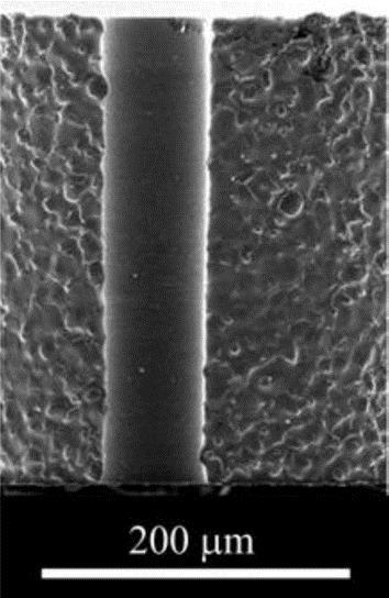
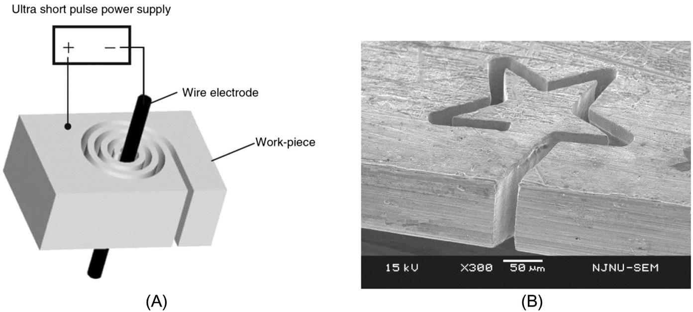
Microwire electrochemical machining (microwire ECM) is another promising machining method. Fig. 5.18A shows the schematic of the principle of the microwire ECM process in which a microwire is used as a tool electrode. In contrast to wire EDM, a thinner wire can be used as the wire will not be worn out, (Kim et al., 2005; Wang, Zhu, Zeng, & Liu, 2011). In the process, pulse voltage is applied between the workpiece and the wire electrode in an electrolyte cell. The workpiece is electrochemically dissolved and a narrow slit is produced as the cathode wire moves toward the anode workpiece. Fig. 5.18B illustrates a microstructure machined by wire ECM. Fig. 5.19 presents a method of fabricating a microtool using wire ECM in which a micrometallic rod is controlled to allow rotation and a wire electrode of tens of microns feeds to the rod to perform the cutting (Liu, Zeng, & Zhang, 2014).

5.2.5 Microelectrochemical jet machining
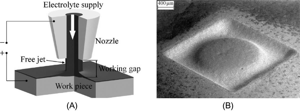
Electrochemical jet machining (ECJM), as described by Kozak, Rajurkar, and Balkrishna (1996), employs an electrolyte jet impinging on a metal workpiece to achieve anodic dissolution of the target material. The nozzle through which the electrolyte jet emerges forms the cathode while the workpiece acts as the anode, and a DC voltage is applied across the electrolyte jet and the workpiece (Liu, Nouraei, Papini, & Spelt, 2014), as demonstrated in Fig. 5.20A. ECJM can be used to drill narrow cooling holes in aircraft turbine blades and to fabricate patterns of microgrooves and slots in microelectronic parts without using masks to define the features. One advantage of ECJM is that it does not require the entry of the nozzle into the machined geometry because an adequate current flow and the machining rate can be achieved while maintaining a proper standoff distance between the nozzle cathode and the workpiece. Other advantages are the relatively low cost of the equipment and the absence of any requirement for a preformed cathode having the shape of the desired machined feature. Natsu, Ooshiro, and Kunieda (2008) used ECJM to fabricate microgrooves in stainless steel by using a 50 μm diameter scanning nozzle. Hackert-Oschaetzchen, Martin, and Meichsner (2013) presented microstructures, with one of them illustrated in Fig. 5.20B, machined by ECJM in tungsten carbide using electrolyte solutions—sodium nitrate, sodium chloride, and sodium hydroxide.
5.3 Hybrid processes associated with microelectrochemical machining
ECM has continuously received interest as an industrial machining process in the last two decades, especially for producing micro and small parts. One of the main advantages of ECM is that it does not cause any thermal stresses or heat-affected zones to the workpiece. This fact is the basis for some hybridizations of ECM with other processes such as EDM, striving to combine advantages of speed, and accuracy with a good surface finish by chemically dissolving any thermally affected layers (Silva, Pajak, Mcgeough, & Harrison, 2011). There are other hybrid processes that combine the micro-ECM to obtain a better localized removal of material.
5.3.1 Laser-induced electrochemical jet machining
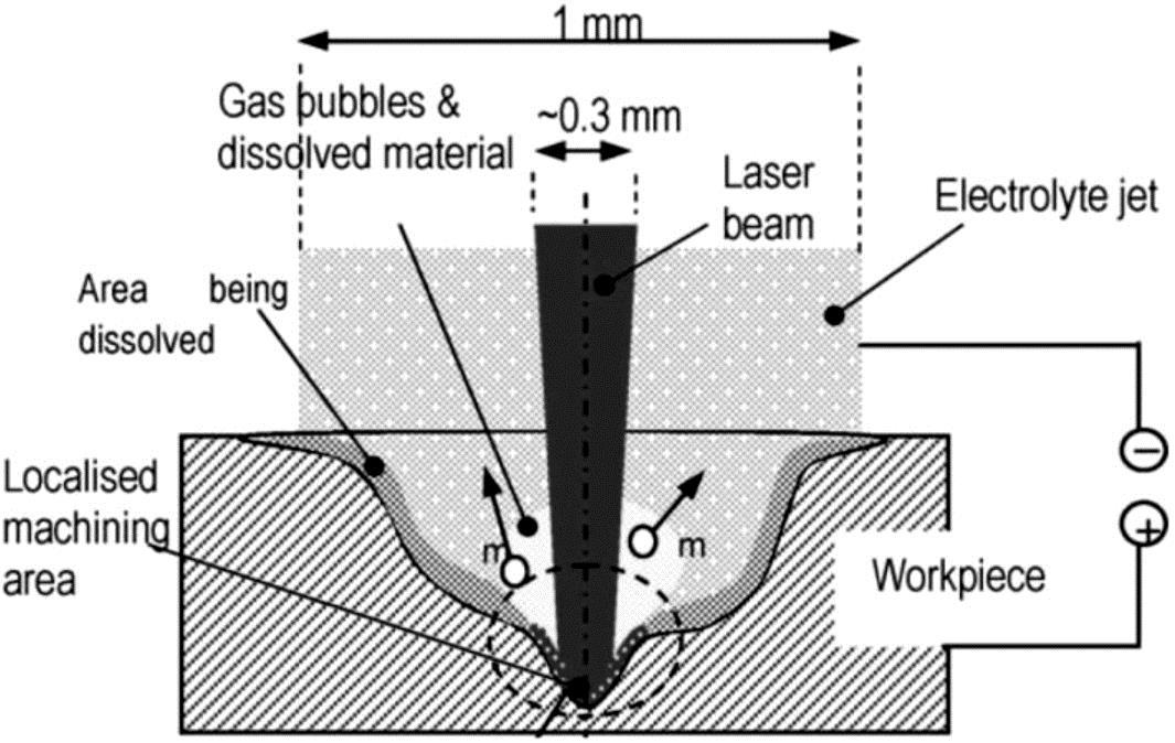
Laser-induced electrochemical jet machining (LAECJM) is a hybrid process in which the laser beam is aligned coaxially with the jet of the electrolyte, creating a noncontact tool electrode. The process combines two different sources of energy simultaneously: energy of ions ECM and energy of photons (a laser beam). The main aim of combining a laser with a jet of electrolyte is to assist electrochemical dissolution from a specific workpiece surface area. Electrochemical dissolution is the main material removal mechanism supported by the parallel action of the low-power laser beam. The laser does not remove any material, but assists dissolution by its thermal activation. Thermal energy enhances the kinetics of electrochemical reactions providing faster dissolution. It also aids in breaking down the oxide layer found on some materials in certain electrolytes that inhibit efficient dissolution (Silva et al., 2011; Pajak, Desilva, Harrison, & Mcgeough, 2006; Long, Xiong, Shi, & Liao, 2015). Fig. 5.21 illustrates the principles of hybrid LAECJM. For hole or slot machining, material removal is more profound in the axial rather than in the lateral direction for LAECJM.
5.3.2 Abrasive enhanced electrochemical jet machining
Abrasive enhanced electrochemical jet machining (AECJM), as shown in Fig. 5.22A, is a machining process which employs a premixed slurry jet (electrolyte mixed with abrasives) and a DC potential applied between the jet nozzle and target to remove material through anodic dissolution, erosion, and synergistic effects (Liu et al., 2014; Liu, Nouraei, Spelt, & Papini, 2015). It is a hybrid process that combines ECJM with abrasive slurry jet machining (ASJM), in which a premixed abrasive slurry is pumped at a relatively low pressure through an orifice to erode the target. The combined process of AECJM can achieve significantly higher metal removal rates than either ASJM or ECJM alone and produces smoother surfaces than ECJM alone. The major synergistic effects in ECJM are expected to depend on the target material and utilized process parameters. For example, in the case of the ESJM of ferrous metals using a NaCl solution, no oxide film will be developed on the target, and the corrosion simply enhances the rate of metal removal due to erosion. However, in the case of the ESJM of WC using an NaCl solution, an oxide film is expected to rapidly develop and be removed by impacting particles, thus exposing new material to the electrolyte, leading to a continuous anodic dissolution. Fig. 5.22B shows a microchannel machined by AECJM in tungsten carbide using sodium chloride as an electrolyte.

5.3.3 Process combining EDM with ECM
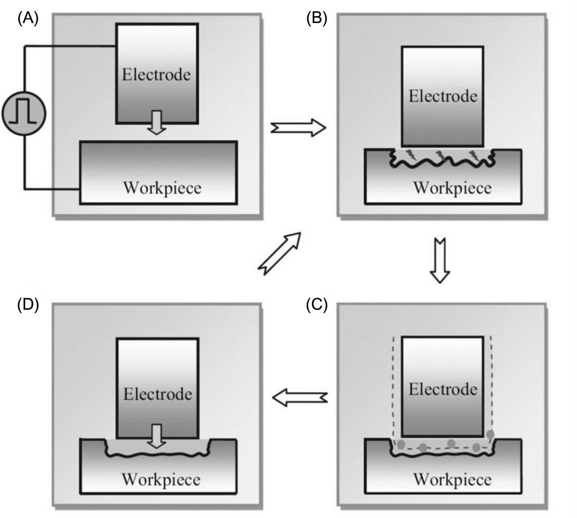
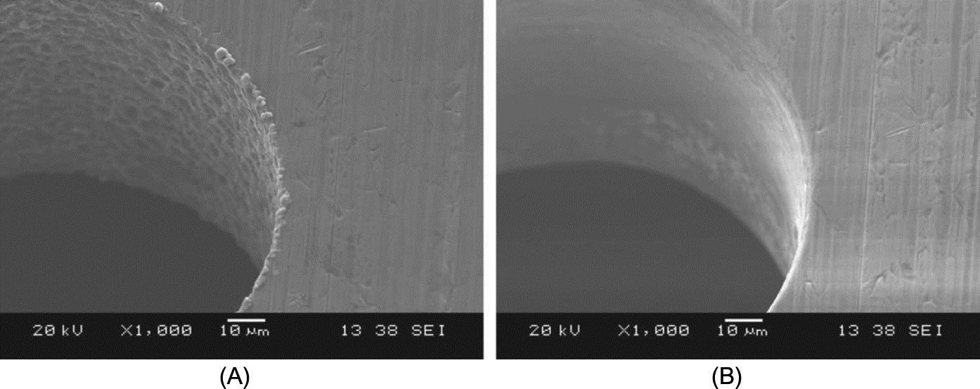
In micro-EDM, the material is removed by vaporization and melting during each electric discharge. Therefore, the machined surface is made up of thermally damaged layers consisting of the white layer and the heat-affected zones (Nguyen, Rahman, & Wong, 2012). Microcracks and residual stresses are also observed in these layers. The surface machined by micro-EDM has high surface roughness due to discharged craters. On the other hand, micro-ECM has some valuable advantages, e.g., the machined surface is very smooth, stress-free with no burr and microcracks, and has no thermally affected layers. Hence, an appropriate combination of micro-EDM and micro-ECM could yield the advantages of these two processes while preventing their disadvantages (Zeng, Wang, Wang, Shan, & He, 2012). Fig. 5.23 shows the principle of a simultaneous micro-EDM and micro-ECM (SEDCM) process in low-resistivity deionized water (Nguyen et al., 2012). The primary aims of the process are to use electrochemical dissolution to lower the surface roughness and remove the thermally damaged zones created during EDM. Fig. 5.24 demonstrates the machining results of a microhole in the absence and presence of an electrochemical dissolution effect (Nguyen, Rahman, & Wong, 2013).
5.4 Conclusions
Technological advances made in microelectrochemical machining, which reflect the state of the art in academic and industrial achievements and applications, have been presented in this chapter. Micro-ECM has clearly emerged as an indispensable part of micromanufacturing technologies. The demonstrated processes offer the two- and three-dimensional machining capabilities of processing a wide variety of engineering structures, including microholes, slots, grooves, tools, texturing, and complex surface in metals. Micro-ECM of complex dimensional features, development of machining and control systems, and combinations with other processes are in progress. Increasing requirements and applications of micro-ECM technologies will be foreseen in the future in industries of aerospace, automotive, electronics, and medical devices.
Acknowledgment
The authors acknowledge the support of Natural Science Foundation of Jiangsu Province of China (Grant No. SBK2015020754). Zhuang Liu gratefully acknowledges the Scientific Research Foundation for the Returned Overseas Chinese Scholars, State Education Ministry and Jiangsu Key Laboratory of Precision and Micro-Manufacturing Technology.