
Underwater pulsed laser beam cutting with a case study
N. Roy, A.S. Kuar and S. Mitra, Jadavpur University, Kolkata, West Bengal, India
Abstract
This chapter gives an overview of a nanosecond pulsed neodymium-doped yttrium aluminum garnet (Nd:YAG) laser beam cutting at submerged condition. A brief illustration of basic nanosecond pulsed laser beam workpiece material interaction is given here; the illustration considers generation of photon and interaction with electron to generate heat, absorption of heat, phase transformation, plasma generation, ablation and removal mechanism of cut material from the irradiate region, both at dry and submerged conditions. The reason to use a water environment during laser beam cutting is discussed in this chapter. Developments of laser beam cutting at various submerged environments, i.e., either in static or in dynamic conditions, are exemplified in this chapter. An experimental study of Inconel 625 superalloy at static submerged condition is presented as a case study at the end of this chapter. During this experimental study, the effect of different heights of water columns on machining responses along with other process parameters is also discussed in detail.
Keywords
Nanosecond pulsed Nd:YAG laser beam; laser-matter interaction; static underwater laser beam cutting; Inconel 625 superalloy; height of water column
7.1 Introduction
Diverse application of the laser in various fields of science, technology, art and entertainment makes it an invaluable tool for mankind. The invention of the laser has made a very significant contribution to the advancement of science and technology for new materials and process techniques to meet global competition. The laser is a device that emits electromagnetic radiation through the process of stimulated emission. Neodymium-doped yttrium aluminum garnet (Nd:YAG) laser, CO2 laser, fiber laser, diode laser and excimer lasers are widely used for various material processing applications in industries. Nd:YAG laser is one of the most commonly used lasers for drilling, marking, cutting and welding applications. The lasing medium is Neodymium (Nd3+) doped Yattrium Aluminum Garnet (YAG) crystal which is pumped by light source such as arc lamp or flash lamp. The wavelength of the Nd:YAG laser radiation is 1.06 μm which lies in the near-infrared region of the electromagnetic spectrum (Küper & Stuke, 1992).
7.2 Laser as a machine tool
Laser can be considered as one of the nonconventional machining processes because of their precision of operation, low cost, localized processing, flexibility and high speed of operation. Laser beam machining is the machining process involving a beam of laser as machine tool. It is a thermal process where a laser beam is used as a heat source to remove material without mechanical engagement with workpiece. The main properties of laser radiation are high spatial and temporal coherence along with high collimation, high monochromaticity, high brightness and minimal divergence which results in producing a very high intensity laser beam. A wide range of materials can be processed by laser due to its large irradiances (up to 1021 W/cm2) at the surface, with high focusability which is enough to evaporate any material or even to start a nuclear fusion reaction (Küper & Stuke, 1992). In the laser beam machining process, material removal is not dependent on mechanical, physical or electrical properties of the workpiece but on thermo-optical properties of the material (Davim, 2013) (Fig. 7.1).
The beam wavelength has a great impact on absorptivity of laser light on a workpiece surface, which is relatively important for laser material processing. A discrete spatial profile, termed as transverse electromagnetic mode, is exhibited by a cross-section of laser beam. Generally fundamental TEM00 mode is used for laser beam machining operations, having Gaussian spatial distribution. The output of laser can either be constant amplitude or periodic, commonly known as continuous wave (CW) mode and pulsed beam mode respectively. Normal pulsing, Q-switching and mode locking are the various pulsing modes during pulsed laser operation. A high energy density is achieved in short pulse duration laser operation after threshold energy is reached. Pulse duration and pulse repetition rate are the most influencing process parameters for pulsed laser machining (Ready, 1997). During laser beam machining one of two geometrics are generally used i.e. either a moving target or a moving beam.
7.3 Laser material interaction
Reflection, refraction, absorption, scattering and transmission are the physical phenomenans that take place when the electromagnetic wave (laser beam) interacts with a workpiece surface. Linear and nonlinear absorption are the most important phenomena of the laser matter interaction. Fig. 7.2 shows a schematic of interaction of a laser beam with work material.

Absorption at irradiate surface not only depends on the wavelength of the laser radiation but also on other factors such as incident angle, surface roughness and temperature of the solid/machine zone. The absorption coefficient of material is proportional to electrical resistivity whereas the absorption by target substrate increases with decrease in wavelength. The probability of nonlinear absorption increases significantly in proportion to growing laser intensity. This aforesaid relationship is the reason behind multiphoton excitation process at constant laser fluence for a shorter laser–material interaction time. Absorption of laser energy can be described as interaction between electrons and nuclei lattice of target material. A force is exerted by an optoelectric field of incident electromagnetic radiation by which the nuclei lattice and electrons get vibrational motion. Thus the absorbed radiation results in the excess energy of the electrons, such as kinetic energy of the free electrons, excitation energy of the bound electrons (Von, 1987). Excess energy of the electrons is damped by collision with vibrating lattice of nuclei and some incident laser energy is transferred to the lattice leads to generation of heat. By Beer-Lambert law (Steen, 1991), the absorption of laser radiation in the target substrate is generally expressed as,
where I0 is the incident intensity, I(z) is the intensity at depth z and μ is the absorption coefficient. The intensity of the laser radiation gets faded along with the depth inside the material. The length over which the significant reduction of intensity of the laser radiation takes place is known as attenuation length (L) and expressed as reciprocal of the absorption coefficient (μ) of target substrate (Welch & Gardner, 2002),
Generally for opaque material, the absorptivity can be defined as a fraction of incident radiation, absorbed at normal incidence which can be expressed (Duley, 1983) as,
where, A is absorptivity of irradiate substrate and R is the reflectivity of irradiate substrate.
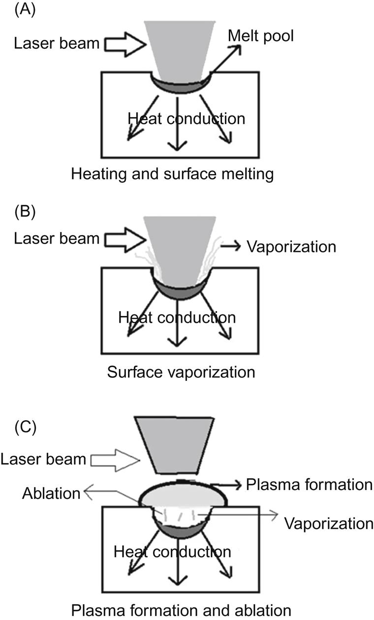
Various physical effects in the material include heating, melting and vaporization of the substrate has occurred, depending on the temperature distributions in the material. Thermal energy is transported through the substrate by thermal conduction, convection and radiation from the surface of the substrate. Phase transformations such as surface melting and evaporation are taking place by sufficiently high laser intensity which is generally referred as melting (Im) and vaporization (Iv) threshold intensity. During laser irradiation, the melting starts at a certain temperature when laser intensity reaches melting threshold energy and creates a solid–liquid interface at the surface. The solid–liquid interface moves away from the surface along the depth with increase in laser energy density and a melt pool is formed. The depth of melting is decreased during pulsed off time (Allmen, 1983). The depth of melting (Z max) reaches maximum when the laser irradiates surface temperature reaches at boiling point. Evaporation takes place with a further increase in laser power density and/or pulse on time, resulting in material removal from irradiate region. The liquid–vapor interface has to move inside the material with continuous laser irradiation after the vaporization is initiated. Depth of vaporization (Steen, 1991), mass of material removed per unit time and velocity of the liquid–vapor interface can be calculated by
where ![]() the mass of material removed per unit time, Vs is the velocity of the liquid–vapor interface and ρ is the density.
the mass of material removed per unit time, Vs is the velocity of the liquid–vapor interface and ρ is the density.
where, ![]() is the pulse time and d is the depth of vaporization.
is the pulse time and d is the depth of vaporization.
where, H is the absorbed laser power, Tb is the boiling temperature at surface, and Lv is the latent heat of vaporization. Evaporation-induced recoil pressure exceeds the highest possible value of surface tension pressure during laser beam processing, i.e., drilling, cutting, marking, welding, cladding, etc. During laser material processing, recoil pressure plays an important role in melt expulsion from machining zone (Steen, 1991). At high laser irradiance (I≥109 W/cm2) the vapor or the ambient gas becomes ionized due to the interactions between the resulting vapor and the incident laser beam, termed as plasma. Plasma plume forms a shield over the machining area and reduces the energy available to the workpiece. When the incident laser energy on the target surface is sufficiently large to exceed the boiling temperature, rapid vaporization starts. In the photo-thermal ablation process, material is removed by thermal stresses and surface vaporization. Whereas in photo-chemical ablation, material removal takes place by molecular fragmentation without significant thermal damage by the energy of the incident photon causes the direct bond breaking of the molecular chains in the organic materials (Bäuerle, 2000). The physical phenomena of material removal mechanism are shown in Fig. 7.3.
Utilization of the laser in various manufacturing process is increasing rapidly. The applications of lasers have been demonstrated in many casting, forming, joining, and machining processes. The laser beam machining process is widely used in industries. Laser beam cutting, drilling and welding are the most common applications in automotive, medical and aircraft industries.
7.4 Laser beam cutting
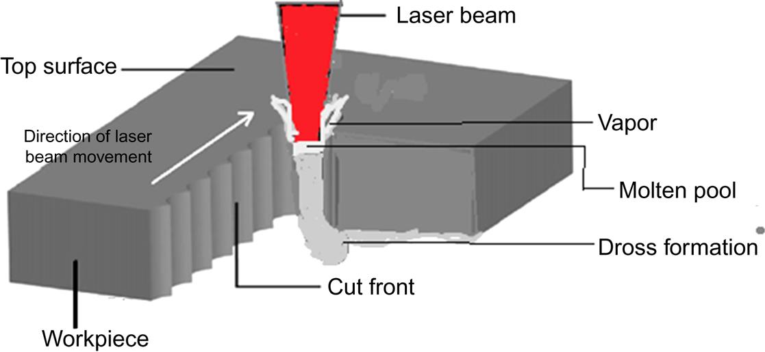
Nowadays the laser beam cutting technique is the most established laser material processing technology to obtain desired geometry. It is the two-dimensional laser beam machining technique where the motion of either focused beam and/or the workpiece are relative to each other. Advantages of laser beam cutting can be divided into two categories (Powell, 1993), i.e., process characteristics and cut quality. The schematic diagram of laser beam cutting is illustrated in Fig. 7.4.
7.4.1 Process characteristics
It is a noncontact, thermal, high speed, and repeatable method to process a wide range of materials with different thickness.
1. There is no tool wear and mechanical damages on and adjacent to machining zone.
2. The workpiece does not need to be clamped or accurately positioned. Instead of that it must be properly focused or marginally de-focused as per machining requirement.
3. Most of the laser beams cutting machines are CNC-controlled to ensure the desired geometry and cutting speed.
7.4.2 Cut quality characteristics
7.4.3 Principles of laser beam cutting
During laser beam cutting, the laser beam interacts with workpiece material. The laser energy absorbed by the workpiece material transforms into thermal energy which heats up, subsequently melts and vaporizes the irradiate region of the workpiece locally/throughout the thickness, thus creating a cutting front. Melt pool or vapor is expelled from the machining zone by the hydrodynamic nature of melt pool, vapor and by assist gas axially/coaxially flown. Assist gas also cools the machining zone as well as takes part in chemical reactions such as oxidation or carburization of material to help in enhancement of material removal if reactive in nature (Chryssolouris, 1991).
7.4.3.1 Different types of laser beam cutting
Based on the role of assist gas and interaction between the laser beam and the workpiece, the substrate laser beam cutting operation can be classified into four groups, i.e., laser sublimation cutting, controlled fracture technique, fusion cutting, and reactive fusion cutting. Besides these four major laser cutting application/technique, there are few relatively new laser cutting applications evolved in recent times e.g. laser micro cutting, underwater laser cutting etc.
7.4.3.1.1 Laser sublimation cutting
During laser sublimation cutting, latent heat provided by laser energy transforms the target material to the vaporization point and ablates into a vapor state along the cutting seam. Materials with low thermal conductivity and lesser vaporization temperatures are suitable to process by this method. Extremely clean cut edges are achieved due to material removal takes place by direct phase change to vapor state. In this process all the thermal energy is used in evaporation process without any heat conduction in the target region to create a melt pool. Generally nonreactive assist gas flows coaxially to remove the vapor from machining zone (Biyikli & Modest, 1988).
7.4.3.1.2 Controlled fracture technique
In controlled fracture technique, incident laser energy produces mechanical stress on the impingement region of workpiece material which causes the separation of material from the surface of workpiece in a controlled manner along the path of laser beam movement. Less laser energy is required in controlled fracture technique, as material is removed by crack propagation and not by melting or evaporation. A high plastic compressive stress is generated around the laser spot diameter which relaxed with movement of laser beam, results in generation of residual tensile stress on the upper surface of irradiate region. This tensile stress propagates the crack from upper to lower surface of the substrate (Caristan, 2003).
7.4.3.1.3 Laser fusion cutting
Movement of laser beam relative to workpiece makes a straight or curved cut profile during laser fusion cutting. High intensity laser energy from impinging beam absorbed by workpiece substrate melts the metarial throughout the thickness to create a cutting front. Generally, high pressure, nonreactive assist gas, such as argon, or helium is used coaxially to transform momentum to the thin melt pool. Melt film is ejected from the bottom of the kerf as droplets due to vertical acceleration when momentum of the thin melt film exceeds the surface tension force. Otherwise dross formation occurs (Schulz, Simon, Urbassek, & Decker, 1987).
7.4.3.1.4 Reactive fusion cutting
It is a variation of fusion cutting where high pressure reactive assist gas is used instead of inert gas, resulting in exothermic reaction with reactive assist gas (mainly oxygen), when the top surface of workpiece substrate is heated. Exothermic reaction adds another source of heat along with laser irradiation to enhance the rise of molten layer temperature to evaporation, resulting in faster material removal from the machining zone by evaporation. In addition, the melt pool from the bottom of the machining zone removed by the frictional force works between reactive assist gas and the molten layer. The cutting front propagates through the thickness of the workpiece material by further melting at solid–liquid interface below the cutting front in the direction of laser beam movement. Oxidation plays an important role during oxygen-assisted reactive laser cutting. Enormous exothermic heat generation during oxygen-assisted laser cutting operation nullifies the conductive thermal loss of base material. Higher cutting speed is achieved by production of oxide film which has higher absorptivity and higher fluidity of oxide slag in erosion front. This laser cutting technique is mainly used to cut thick metal sheets (O’Neill & Gabzdyl, 2000).
7.4.3.1.5 Laser cutting at different assisted medium
Sometimes the laser cutting process is performed at various atmospheric conditions to obtain the desired cut quality. Laser cutting technique is sometimes performed in a submerged condition or in a preheated condition, or in a vacuum or sometime in a mixture of various conditions to get better cut characteristics.
7.4.3.1.6 Laser beam microcutting
In modern technologies, miniaturization is an important trend to fabricate microparts for biotechnological, microelectronics, telecommunication, MEMS, and medical applications. Laser beam micromachining is used to get microproducts with better flexibility in dimensional design. Ablation and laser-assisted chemical etching are the mechanisms behind material removal in micron or in submicron range during laser beam micromachining operation. Generally laser in NIR (1.06 μm) to deep UV(150 nm) region wavelengths with short pulse duration (<100 ns to few fs) is used for laser beam micromachining operation. Direct writing and mask projection are the most commonly used laser beam micromachining techniques used in industries. Resistor trimming, coronary stent fabrication are some of the applications of laser beam microcutting (Gower, 2000).
7.4.4 Application of laser beam machining
In the manufacturing industry, from automotive to medical, laser beam machining is used to process a wide range of materials with precision in a cost effective way. In the automobile industry, the LBM process is used to manufacture products from airbags to body frames. The laser beam hardening process is used for hardening gear teeth. In aerospace industries various laser beam machining processes are used to produce jet engine components, polymer cabling insulation, titanium ducting, fuselage skin stiffeners, fabrication of body parts, etc. In medical or biomedical industries laser material process is utilized in the fabrication of microfluidic devices, coronary stents, and for manufacturing of various surgical equipment.
7.5 Underwater laser beam machining
Undesired quality aspects, i.e., kerf taper, dross formation, HAZ, recast layer, burr formation, difficulties in debris removal and desired surface morphology during laser cutting are sometimes totally removed or partially corrected by irradiating the workpiece material at submerged condition.
7.5.1 Advantages of laser beam cutting at submerged condition
1. Narrow HAZ is generated due to low thermal load on workpiece.
2. Strong hydrodynamic force generated by bubble dynamics, carries away the debris from machining zone.
3. Shorter wavelength of irradiate laser beam at liquid helps to increase the absorptivity of workpiece at submerged condition.
4. Risk of atmosphere contamination is reduced at submerged condition.
Sometimes water solution of salts or bases or acids are used during submerged laser beam machining to improve the etch rate and finish quality. To improve the wetting quality of water film on workpiece surface, organic additives are added.
7.5.2 Material removal mechanism of nanosecond pulsed laser beam cutting at submerged condition
Along with the absorption, heating, melting/vaporization, and ablation, some other phenomenon also occur during nanosecond pulsed laser beam cutting at submerged condition.
High drag force and low settling velocity in liquid help quick removal of debris from machining zone. Formation of bubbles and thermal gradient generated by laser induced heat cause convection in liquid. In some circumstances fluid in dynamic condition is recommended to avoid scattering and absorption of laser light by debris. Liquid molecules may be excited, ionized, and dissociated by laser-induced plasma temperatures and plasma UV/IR radiation, thus become chemically active (Kruusing, 2004). Restriction of plasma expansion in confined condition enhances the action of laser irradiation. Dissolution of workpiece and debris takes place in supercritical water generated by high intensity laser beam. Collapse of the vapor bubbles generates mechanical impact of microjets resulting in easy removal of debris from machining zone (Li & Achara, 2004).
7.5.3 Development of different types of liquid-assisted laser beam machining
Current research on different types of liquid-assisted laser beam machining, i.e., laser ablation in submerged condition, underwater waterjet guided laser beam machining, underwater gas-assisted laser beam machining, chemical-assisted laser beam machining is carried out by researchers. Some researchers have found that laser beam cutting in chemical solution produces better surface quality than processing in pure water (Datta, Romankiw, & Vigliotti, 1987). Electrochemical dissolution/localized breakdown is enhanced by laser beam in neutral salt solution. Optical absorptivity of workpiece substrate increases in water due to higher refractive index of water (Kim & Lee, 2001).
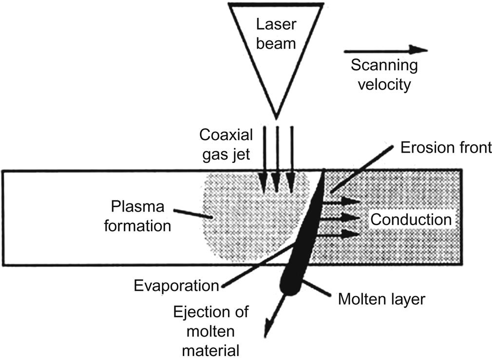
7.5.3.1 Laser beam cutting in submerged condition
In many underwater laser beam cutting techniques, the laser ablation at submerged condition can be said to be the simplest process to cool the workpiece by water during the cutting induced by laser. A schematic view is illustrated in Fig. 7.5. In this technique layer or thin film of stagnant water creates better natural convection than air, which results in reduction in temperature gradient and thermal stress on the top surface of workpiece substrate, thereby reducing the possibility of subsurface crack formation, results in micro crack free machined zone with smaller heat affected zone.

7.5.3.2 Underwater assist gas jet/waterjet assisted laser beam cutting
In this process a high pressure assist gas or waterjet coaxially flows along with high intensity laser beam from a specially designed nozzle for impingement on the top surface of submerged workpiece. Sometime an off axial waterjet is impinged on the irradiation spot by a specially designed delivery nozzle. A schematic view is illustrated in Fig. 7.6. Removal of molten pool from the bottom of the kerf is easier in this process (Mullick et al., 2013). Sometimes a waterjet is directed into the cutting region to increase the thermal efficiency of the laser beam in underwater conditions. Here high intensity laser beam is generally used. The direction of the waterjet in the fusion region results in desired cut quality with higher cutting speed (Owaki, Uehara, & Tsuchiya, 1999).

7.5.3.3 Molten salt-jet-guided/chemical laser beam
In this process, instead of a waterjet a molten salt jet or chemical is used as assisted medium which is directed in fusion zone. Molten salt jet/chemical is used for laser reactive cutting due to higher heat capacity and higher oxygen content by molten salt, which facilitates the removal of the material rapidly. In that instance, high temperature chemical etching of the workpiece surface also takes place, which increases the rate of material removal.
7.5.3.4 Water jet following the laser beam
In this process, the purpose of the waterjet is to confine the assist gas in order to increase the assist gas pressure in kerf which results in improvement in melt removal. This process is suitable for both the high and low intensity laser beam due to absence of the waterjet in the fusion zone (Stephen, 2011). Schematic diagram of this process given below in Fig. 7.7.

7.5.3.5 Laser beam cutting of opaque material at partially submerged condition
In this process during cut melt redeposition on the cutting front at backside is reduced or absent. Liquid prevents the adhesion of debris and dross at the backside of the workpiece.
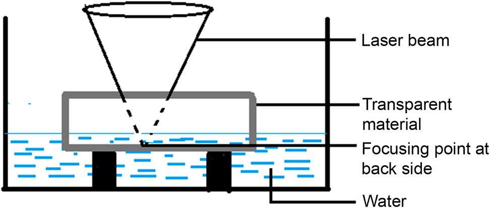
7.5.3.6 Laser beam cutting of transparent material at partially submerged condition
Because of low absorption of the light, inorganic optical materials are difficult to machine with conventional laser cutting techniques. Desired microstructuring can be achieved by this technique. The damage and the optical breakdown threshold at a glass plate in contact with water were 2.5 times higher compared to those in air. Debris is removed efficiently by liquid motion, gravity force and debris dissolution. In this process, the etching threshold value is comparatively less than in air, and etching occurs well below the optical damage threshold of the materials. Absence of plasma shielding results in increased laser cutting efficiency (Kawaguchi, Sato, and Narazaki, 2005). Schematic diagram of this process is shown in Fig. 7.8.
7.5.3.7 Hybrid waterjet laser cutting
In this process a defocused laser beam travels along the workpiece followed by a high pressure waterjet. Here the waterjet flows off axially along the laser beam but enters in the fusion zone. In this process, the laser in defocused position is used to heated up the soft solid state and the material is removed by the impact of the following high pressure waterjet. For that reason, the amount of thermal damage on the workpiece surface and sub-surface regions is minimized. A specially designed mechanism is attached to the workpiece nozzle to change its inclination angle with the laser beam and standoff distance from the workpiece. During this process, compressive stress is generated on the laser-induced heated zone. Forced convection due to waterjet flow generates the quenching effect to the heated region, resulting in formation of tensile stress on the top surface of the workpiece. That tensile stress is the reason behind propagation of cracks leading to removal of material from workpiece specimen with flow of water as microchips (Kalyanasundaram, Shrotriya, & Pal, 2010).
7.6 Pulsed IR laser ablation of Inconel 625 superalloy at submerged condition: A case study
A parametric study on laser beam cutting of Inconel 625 superalloy at submerged condition has been carried out. The effect of the height of water column along with the other laser beam cutting parameters such as lamp current, pulse frequency, pulse width and cutting speed, on kerf width, HAZ width and depth of cut is investigated. Height of the water column is varied from 1 mm to 5 mm to see the effect on machining responses. In this study lamp current is consider as an function of average power or working power. Design of experiment based on response surface methodology (RSM) has been implemented here to carry out the experiments.
7.6.1 Experimental setup
Inconel 625 with 80 mm×80 mm×0.9 mm dimension has been considered as workpiece material for experimental purposes. In this study water is used as assisted medium at stagnant condition. A pulsed Nd:YAG laser-based CNC machining system (SLT-SP- 2000), manufactured by M/s Sahajanand Laser Technology, India, is used for the experimental study. The CNC controller consists of x–y–z axis and a controlling unit. One stepper motor is attached to each of the axes and connected to the controlling unit. A CCD camera is attached over the CNC z-axis controller unit which, along with the CCTV monitor, is used for viewing the location of the workpiece and also for checking the proper focusing condition of surface of the workpiece. The schematic diagram of the underwater pulsed Nd:YAG laser-based CNC machining system is shown in Fig. 7.9.

The workpiece holding unit for underwater laser beam cutting at static condition has been designed and fabricated at the workshop. Transparent PMMA sheets with different thicknesses are used for fabrication of the workpiece holding device. This specially designed workpiece holding unit is placed over the CNC controlled work table. Image of this unit is shown in Fig. 7.10. In this experimental procedure a water film from 1 to 5 mm is used to carry out the experiments. For the study, a laser beam comes from outside, first interacts with water film then travels a distance through the water to strike the workpiece substrate. The workpiece is held in submerged condition by pouring water externally. The height of the water column over the workpiece is maintained precisely by placing the slip gauge over the workpiece material. From the dimension of the slip gauge, the height of the water column over the surface of the workpiece material is controlled as required. A steady state of water column is maintained during the experiment. De-ionized water at room temperature (20–22°C) has been used as water medium because of its nonreactive nature to workpiece material even at elevated temperatures and easy availability. The bubbles accumulated near the fusion region are removed from the machining zone by a thin stick after each experimental run, followed by a few minute wait for stabilization of stagnant water. Jammer is used for precisely fixed the workpiece with proper alignment. The schematic diagram of the underwater pulsed Nd:YAG laser-based CNC machining system is shown in Fig. 7.10.

Experiments have been carried out according to the central composite rotatable second-order design based on RSM. Response surface modeling is used to establish the mathematical relationship between the response, yu and the various machining parameters, with the eventual objective of determining the optimum operating conditions for the system. The ranges of these controllable process variables are selected on the basis of trial experiments conducted by using a one factor at a time approach.
Usually, a second order polynomial equation is used in RSM,
(7.1)
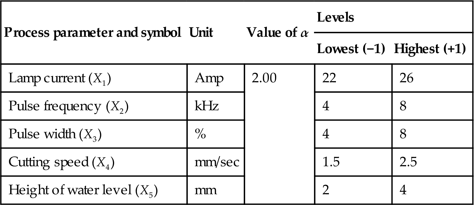
Here yu is the corresponding response, xi is the coded value of the ith machining parameter, k is the number of machining parameters and βi, βii, βij are the second-order regression coefficients. Ranges of all controllable input process variables for underwater laser machining, i.e., lamp current, pulse frequency, pulse width, cutting speed, and height of water level as selected are listed in Table 7.1.
Table 7.1
| Process parameter and symbol | Unit | Value of α | Levels | |
| Lowest (−1) | Highest (+1) | |||
| Lamp current (X1) | Amp | 2.00 | 22 | 26 |
| Pulse frequency (X2) | kHz | 4 | 8 | |
| Pulse width (X3) | % | 4 | 8 | |
| Cutting speed (X4) | mm/sec | 1.5 | 2.5 | |
| Height of water level (X5) | mm | 2 | 4 | |
Images of cut region have been captured by Olympus (Model STM 6-F10-3; No. OH13697) optical measuring microscope at 20× magnification. Here heat affected zone (HAZ) is measured by measure the area of change in colour adjacent to machined zone. Then the machining responses are evaluated by image analysis software. Calculation of HAZ width is governed by the formula given below,
(7.2)
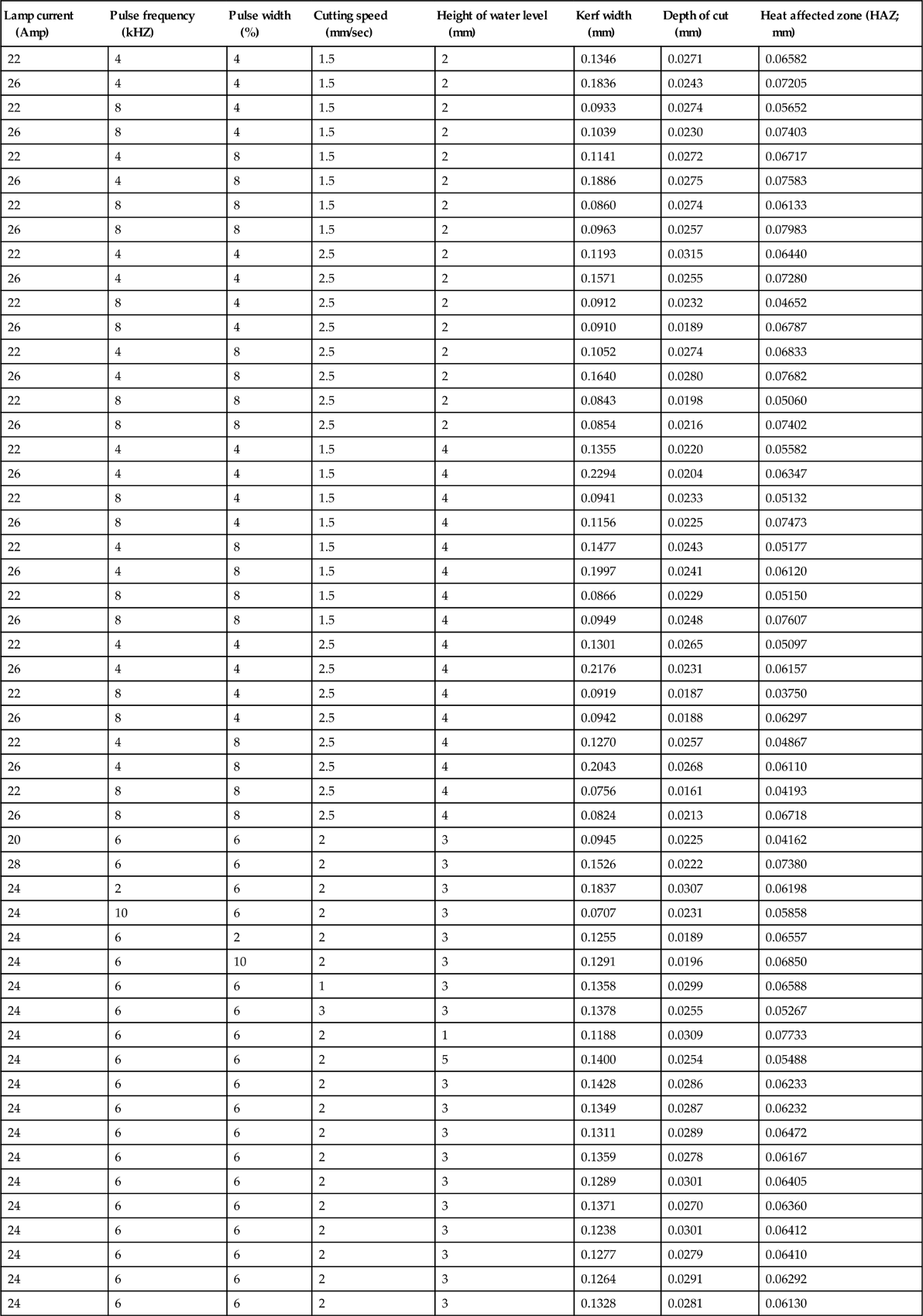
Machining responses are measured at five different positions along the kerf for all experiments and an average is taken for further analysis to reduce the measurement error. Experimental results are listed in Table 7.2.
Table 7.2
| Lamp current (Amp) | Pulse frequency (kHZ) | Pulse width (%) | Cutting speed (mm/sec) | Height of water level (mm) | Kerf width (mm) | Depth of cut (mm) | Heat affected zone (HAZ; mm) |
| 22 | 4 | 4 | 1.5 | 2 | 0.1346 | 0.0271 | 0.06582 |
| 26 | 4 | 4 | 1.5 | 2 | 0.1836 | 0.0243 | 0.07205 |
| 22 | 8 | 4 | 1.5 | 2 | 0.0933 | 0.0274 | 0.05652 |
| 26 | 8 | 4 | 1.5 | 2 | 0.1039 | 0.0230 | 0.07403 |
| 22 | 4 | 8 | 1.5 | 2 | 0.1141 | 0.0272 | 0.06717 |
| 26 | 4 | 8 | 1.5 | 2 | 0.1886 | 0.0275 | 0.07583 |
| 22 | 8 | 8 | 1.5 | 2 | 0.0860 | 0.0274 | 0.06133 |
| 26 | 8 | 8 | 1.5 | 2 | 0.0963 | 0.0257 | 0.07983 |
| 22 | 4 | 4 | 2.5 | 2 | 0.1193 | 0.0315 | 0.06440 |
| 26 | 4 | 4 | 2.5 | 2 | 0.1571 | 0.0255 | 0.07280 |
| 22 | 8 | 4 | 2.5 | 2 | 0.0912 | 0.0232 | 0.04652 |
| 26 | 8 | 4 | 2.5 | 2 | 0.0910 | 0.0189 | 0.06787 |
| 22 | 4 | 8 | 2.5 | 2 | 0.1052 | 0.0274 | 0.06833 |
| 26 | 4 | 8 | 2.5 | 2 | 0.1640 | 0.0280 | 0.07682 |
| 22 | 8 | 8 | 2.5 | 2 | 0.0843 | 0.0198 | 0.05060 |
| 26 | 8 | 8 | 2.5 | 2 | 0.0854 | 0.0216 | 0.07402 |
| 22 | 4 | 4 | 1.5 | 4 | 0.1355 | 0.0220 | 0.05582 |
| 26 | 4 | 4 | 1.5 | 4 | 0.2294 | 0.0204 | 0.06347 |
| 22 | 8 | 4 | 1.5 | 4 | 0.0941 | 0.0233 | 0.05132 |
| 26 | 8 | 4 | 1.5 | 4 | 0.1156 | 0.0225 | 0.07473 |
| 22 | 4 | 8 | 1.5 | 4 | 0.1477 | 0.0243 | 0.05177 |
| 26 | 4 | 8 | 1.5 | 4 | 0.1997 | 0.0241 | 0.06120 |
| 22 | 8 | 8 | 1.5 | 4 | 0.0866 | 0.0229 | 0.05150 |
| 26 | 8 | 8 | 1.5 | 4 | 0.0949 | 0.0248 | 0.07607 |
| 22 | 4 | 4 | 2.5 | 4 | 0.1301 | 0.0265 | 0.05097 |
| 26 | 4 | 4 | 2.5 | 4 | 0.2176 | 0.0231 | 0.06157 |
| 22 | 8 | 4 | 2.5 | 4 | 0.0919 | 0.0187 | 0.03750 |
| 26 | 8 | 4 | 2.5 | 4 | 0.0942 | 0.0188 | 0.06297 |
| 22 | 4 | 8 | 2.5 | 4 | 0.1270 | 0.0257 | 0.04867 |
| 26 | 4 | 8 | 2.5 | 4 | 0.2043 | 0.0268 | 0.06110 |
| 22 | 8 | 8 | 2.5 | 4 | 0.0756 | 0.0161 | 0.04193 |
| 26 | 8 | 8 | 2.5 | 4 | 0.0824 | 0.0213 | 0.06718 |
| 20 | 6 | 6 | 2 | 3 | 0.0945 | 0.0225 | 0.04162 |
| 28 | 6 | 6 | 2 | 3 | 0.1526 | 0.0222 | 0.07380 |
| 24 | 2 | 6 | 2 | 3 | 0.1837 | 0.0307 | 0.06198 |
| 24 | 10 | 6 | 2 | 3 | 0.0707 | 0.0231 | 0.05858 |
| 24 | 6 | 2 | 2 | 3 | 0.1255 | 0.0189 | 0.06557 |
| 24 | 6 | 10 | 2 | 3 | 0.1291 | 0.0196 | 0.06850 |
| 24 | 6 | 6 | 1 | 3 | 0.1358 | 0.0299 | 0.06588 |
| 24 | 6 | 6 | 3 | 3 | 0.1378 | 0.0255 | 0.05267 |
| 24 | 6 | 6 | 2 | 1 | 0.1188 | 0.0309 | 0.07733 |
| 24 | 6 | 6 | 2 | 5 | 0.1400 | 0.0254 | 0.05488 |
| 24 | 6 | 6 | 2 | 3 | 0.1428 | 0.0286 | 0.06233 |
| 24 | 6 | 6 | 2 | 3 | 0.1349 | 0.0287 | 0.06232 |
| 24 | 6 | 6 | 2 | 3 | 0.1311 | 0.0289 | 0.06472 |
| 24 | 6 | 6 | 2 | 3 | 0.1359 | 0.0278 | 0.06167 |
| 24 | 6 | 6 | 2 | 3 | 0.1289 | 0.0301 | 0.06405 |
| 24 | 6 | 6 | 2 | 3 | 0.1371 | 0.0270 | 0.06360 |
| 24 | 6 | 6 | 2 | 3 | 0.1238 | 0.0301 | 0.06412 |
| 24 | 6 | 6 | 2 | 3 | 0.1277 | 0.0279 | 0.06410 |
| 24 | 6 | 6 | 2 | 3 | 0.1264 | 0.0291 | 0.06292 |
| 24 | 6 | 6 | 2 | 3 | 0.1328 | 0.0281 | 0.06130 |
7.6.2 Development of mathematical model
Response surface modeling (central composite design) is used to establish the mathematical relationship between the response and variable process parameters. The second order polynomial equations are given below:
(7.3)
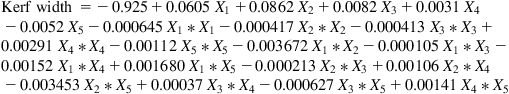 (7.3)
(7.3)(7.4)
 (7.4)
(7.4)(7.5)
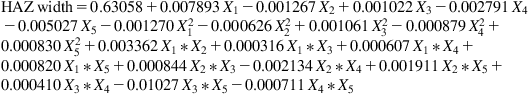 (7.5)
(7.5)7.6.3 ANOVA analysis
Analysis of variance (ANOVA) and subsequent f- and p-value tests have been carried out on machining responses, i.e., kerf width, depth of cut, and HAZ width to test the adequacy of the corresponding developed mathematical models. From the Table 7.3 it is observed that p value of the model for all the machining responses is less than 0.05 (i.e., α=0.05, or at 95% confidence level) indicating a statistical significance. From the p value it is also observed that all the machining parameters are significant individually along with their square terms and 2-way interaction terms, except the square terms for kerf width. From the f value it is observed that lamp current is the most dominating factor for HAZ width but moderate in terms of kerf width and lesser dominant for depth of cut. Pulse frequency has the most dominant factor both the kerf width and depth of cut but a lesser dominant for HAZ width. Pulse width is the least dominant for all the responses. Cutting speed is more dominant factor depth of cut and HAZ width but lesser dominant for kerf width. Height of water level or column shows moderate dominancy for all the responses in which it has most dominant for HAZ width followed by depth of cut and kerf width. Values of other adequacy measures R-sq, adjusted R-sq, and predicted R-sq are in reasonable agreement and are close to 100%, which indicate adequacy of the model. Microscopic view of HAZ width is given in Fig. 7.11. A varying HAZ width along the kerf shown in microscopic view.
Table 7.3
ANOVA analysis of machining responses
| Machining responses | Kerf width | Depth of cut | HAZ width | ||||
| Source | DF | f value | p value | f value | p value | f value | p value |
| Model | 20 | 45.47 | 0.000 | 37.49 | 0.000 | 196.8 | 0.00 |
| Linear | 5 | 156.67 | 0.000 | 52.05 | 0.000 | 641.99 | 0.00 |
| Lamp current | 1 | 166.32 | 0.000 | 5.98 | 0.020 | 2040.49 | 0.00 |
| Pulse frequency | 1 | 576.06 | 0.000 | 139.23 | 0.000 | 52.53 | 0.00 |
| Pulse width | 1 | 5.89 | 0.021 | 6.91 | 0.013 | 34.19 | 0.00 |
| Cutting speed | 1 | 10.69 | 0.003 | 24.47 | 0.000 | 255.17 | 0.00 |
| Height of water level | 1 | 24.40 | 0.000 | 83.65 | 0.000 | 827.58 | 0.00 |
| Square | 5 | 1.32 | 0.282 | 63.39 | 0.000 | 24.22 | 0.00 |
| 2-Way interaction | 10 | 11.95 | 0.000 | 17.25 | 0.000 | 60.49 | 0.00 |
| Error | 31 | ||||||
| Lack of fit | 22 | 2.85 | 0.053 | 2.85 | 0.603 | 0.85 | 0.645 |
| Pure error | 9 | ||||||
| Total | 51 | ||||||
| Machining responses | Value of S | R-sq | R-sq(adjusted) | R-sq(predicted) |
| Kerf width | 0.0086769 | 96.70% | 94.58% | 88.71% |
| Depth of cut | 0.0009534 | 96.03% | 93.47% | 88.72% |
| HAZ width | 0.0011052 | 99.22% | 98.71% | 97.72% |


7.6.4 Effects of different process parameters on machining responses
7.6.4.1 Effect of different process parameters on kerf width
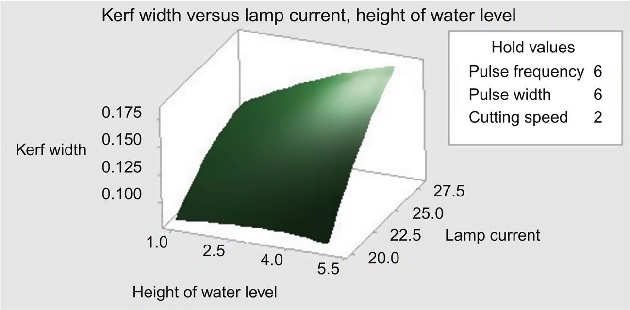
From the Fig 7.12 it is observed that kerf width marginally increases with an increase in height of water level, then decreases with further increase in height of water level. With increase in water column bubbles form and their collapsing is moved away from fusion zone results in increase in material removal. But further increase in water column results in increase of travel distance for laser beam to interact with work substrate. For that absorption of laser energy by water increase, results in decrease in material removal. With increase in lamp current more laser power generates, which travels through the thin water column to interact with the workpiece which may result in more material being removed from fusion zone due to hydrodynamic mechanism.
7.6.4.2 Effect of different process parameters on depth of cut
Here from Fig. 7.13 it is observed that depth of cut decreases with the increase in water level height, and decreases with increase in cutting speed. Increase in cutting speed means less interaction time of the laser beam with the workpiece per pulse. For that reason less penetration may be achieved, resulting in decrease in depth of cut with increase in cutting speed. In underwater machining, laser energy is absorbed by water resulting in a lesser amount of laser fluence to interact with top surface of workpiece which also produces vapor bubbles and superheated water. These vapor bubbles sometimes may scatter the laser beam from its irradiation point, which may be the reason behind the decrease in depth of cut with increase in height of water level.

7.6.4.3 Effect of different process parameters on HAZ width
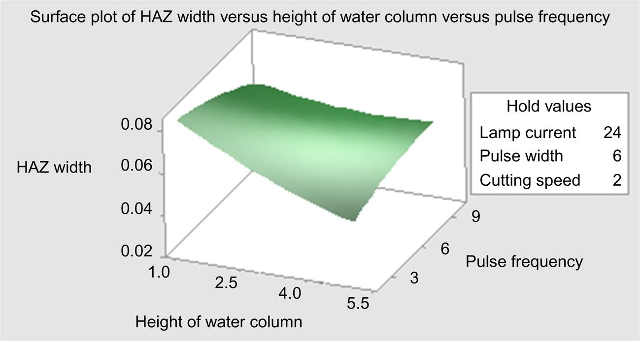
At lower laser pulse frequency, more laser power is generated than at higher pulse frequency, which could account for the amount of material removal. During underwater laser beam machining, settling time of the debris material removed from cut zone is much longer and the scattering and absorption of thermal energy of laser beam is greater. For that reason during laser machining at submerged condition, HAZ width is decreased with increase in pulse frequency. With change in height of water column, the refractive index changes linearly result in less heat input to the top surface of the workpiece. For that reason HAZ width may be decreased with increase in height of water column (Fig. 7.14).
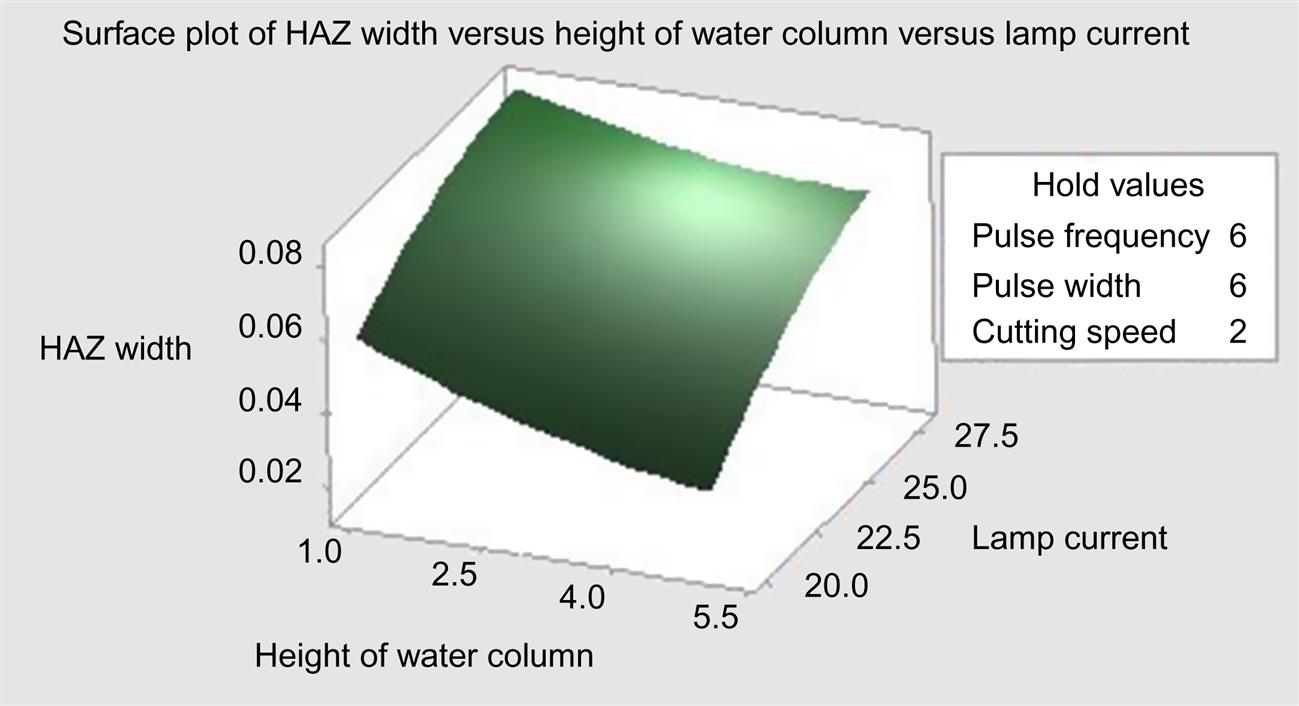
From Fig. 7.15 it is observed that, with increase in height of water column, the laser energy reaching the workpiece surface is reduced; this may be due to the absorption of laser energy by ionization of water and laser beam scattering by water vapor formed in the laser–material–water interaction zone which results in a lesser amount of HAZ width along the kerf. Higher energy density of laser beam causes by increase in lamp current, resulting in more heat input to the fusion zone to increase the HAZ width.
Conclusion
In this chapter a overview on Nano second pulsed laser beam machining has been discussed. Illustration of laser matter interaction and material removal of short pulsed laser beam machining is given. Difficulties of pulsed laser ablation is discussed. Remedy of this difficulties in form of laser machining at different environments, specially in underwater is illustrated. Developments of laser material interaction in submerged condition is exemplified.
Laser beam micromachining of Inconel 625 superalloy at submerged condition has been experimentally studied here. Center composite design-based DOE technique is used here to carry out the experiments. The effect of height of a water column along with other controllable process parameters, i.e., lamp current, pulse frequency, pulse width and cutting speed on kerf width, depth of cut, and HAZ width are investigated successfully. According to result of ANOVA during experimental study, carried out within the selected range, it has to be seemed that height of water column has a great effect on all the machining responses. Lamp current which is used here as an function of average power is the most influencing process variable whereas pulse width is the least affecting factor for all the machining responses. HAZ width, kerf width and depth of cut is decreased with increase in height of water.
Acknowledgment
The authors acknowledge University Grants commission (UGC), New Delhi, for financial support under the scheme of Rajiv Gandhi National Fellowship Programme and CAS Ph-IV (UGC) programme of Production Engineering Department, Jadavpur university, Kolkata, INDIA for technical equipment support.