
Micromachining technique based on the orbital motion of the diamond tip
Y.D. Yan, B. Xue and X.S. Zhao, Harbin Institute of Technology, Harbin, Heilongjiang, China
Abstract
This chapter discusses a micromechanical machining technique based on the orbital motion of the diamond tip. The chapter first describes its principle and establishment of the setup based on this idea. The chapter then studies the micromachining mechanism, the formation mechanism, and control methods of burrs and effects of the processing parameters, and then it gives the examples of fabricating typical microstructures. Finally, some future works are included.
Keywords
Orbital motion; diamond tip; micromachining; micromilling
3.1 Introduction
The microfluidic technique is developing rapidly with the development of the micromachining technique. The typical channel dimension on the microfluidic chip is several hundreds of micrometers. With the development of the microfluidic technique, smaller dimensions from several micrometers to nanometers are required. The existing micromachining techniques have difficulty meeting some of the requirements, such as dimensions, materials, accuracy, and complexity of the microchannels. Moreover, micro- or nanostructures also have significant importance in the fields of medicine, electronics, and optics. Therefore, it is meaningful to study novel micromachining techniques.
The micromachining technique mainly includes the lithography, the chemical reaction based the micromachining and micromechanical machining technique. The lithography technique is a batch processing method. The disadvantages are limited processing materials, difficulty to process three dimensional (3D) microstructures, and high cost (Madou, 2002). The chemical reaction based the micromachining technique can easily fabricate 3D microstructures. However its shortcomings include a difficulty to precisely control the machined depth and remove the damage of the subsurface, owing to the thermal and chemical reactions (Brousseau, Dimov, & Pham, 2010). The micromechanical machining technique can machine complex microstructures on many kinds of materials, with a perfect surface quality and form accuracy (Dornfeld, Min, & Takeuchi, 2006). Simultaneously, our previous works have verified that the mechanical machining can reach to a nanometer scale, using the atomic force microscope (AFM) based nanoscratching method. Within twenty micrometers, 3D micro/nanostructures are successfully machined (Yan et al., 2010; Yan, Sun, & Dong, 2007; Yan, Xue, Hu, & Wu, 2015). Thus, the micromechanical machining technique has attracted more attention in recent years.
The micromilling technique has already been used to machine microchannels (Vazquez, Rodriguez, Elias-Zuniga, & Ciurana, 2010). However, with a decrease in dimension, the low stiffness of the cutter and materials piled up are prone to break the cutter, owing to its high speed spindle rotation. This condition is more serious when the diameter of the cutter is less than 0.2 mm. It is very difficult to machine complex 3D microstructures or microchannels with a width of less than 0.1 mm (Tansel, Rodriguez, Trjillo, Paz, & Li, 1998). Some studies have been carried out to improve this technique, such as the manufacturing of a smaller milling cutter with a focused ion beam method, in order to machine smaller structures (Friedrich & Vasile, 1996), and the employment of vibrations to reduce the tool wear and improve the surface quality (Shen, Zhang, Xing, & Zhao, 2011). However, because the high speed spindle must be used in the conventional micromilling process, microstructures with high accuracy cannot be achieved at an affordable cost.
At present, the AFM-tip based nanomechanical machining technique is confirmed to be a potential method to machine micro- or nanostructures (Yan, Xue, et al., 2015). However the low machining efficiency of this technique restricts its application in the micro- and nanofluidic fields. Some scholars put forward some new methods to solve this problem. For example, Gozen et al. (2012a, 2012b) proposed the AFM-tip based nanomilling technique. The AFM tip is directly moved by a piezoelectric actuator in the horizontal or vertical plane with circular trajectories. Nanostructures with the width of 1 μm and the depths of less than 500 nm ere successfully machined by this method with a high efficiency. Geng et al. (2013) combined the AFM tip’s reciprocal scanning and a movement of a high precision stage to develop a different novel AFM-tip based nanomilling method. Using this method, the nanochannels with the width of 5–10 μm and the depth of 200–500 nm were fabricated with a length of 1 mm. Obviously, the AFM-tip based nanomilling process is a potential method to machine the nanochannels on the nanofluidic chip. But for the microchannels with the width from 10 μm to 100 μm and the depths larger than 1 μm, this technique is not feasible.
Therefore, there is a dimensional gap between the conventional micromilling process and the AFM-tip based nanomilling process. Recently, Heamawatanachai and Bamberg (2009, 2010) presented a novel milling process based on an orbital motion of a diamond tip. This technique takes advantage of the AFM-tip based nanomilling process and overcomes the disadvantage induced by the high rotation spindle of the micromilling process. In their works, a conical diamond tip is used as the microcutter that is driven by a piezoelectric tube scanner instead of a high speed spindle. They have already showed that this technique has the ability of machining the required dimensions of the microstructures mentioned before. However, in their studies, only the conical diamond tip is used, and due to the deflections of piezoelectric tube, the posture of the tool is constantly changing along with the movement. More studies should be done to ask questions such as: (1) What’s effect of the tip’s shape on the machining process? (2) Is the pyramidal diamond tip more feasible for machining? The piezoelectric tube scanner is used to move the tip. The frequency of its motion can meet this requirement. However, it must be compensated, owing to the fact that the coupling effects of the movements are in three directions, and the machining dimension is restricted by the scanner’s scanning range. Therefore, in this chapter, a similar setup based on the orbital motion of the diamond tip is established. The pyramidal and conical diamond tips are both employed. Their effects on the machining process are studied. A nanopiezo stage with a larger moving range is used instead of the piezoelectric tube scanner, which can keep the posture of the tool constant during the machining process. The mechanisms of the burr formation and the removal states of the material are studied in detail. Finally, the complex microstructures are machined by this technique.
3.2 Principle of micromachining using the orbital motion of the diamond tip
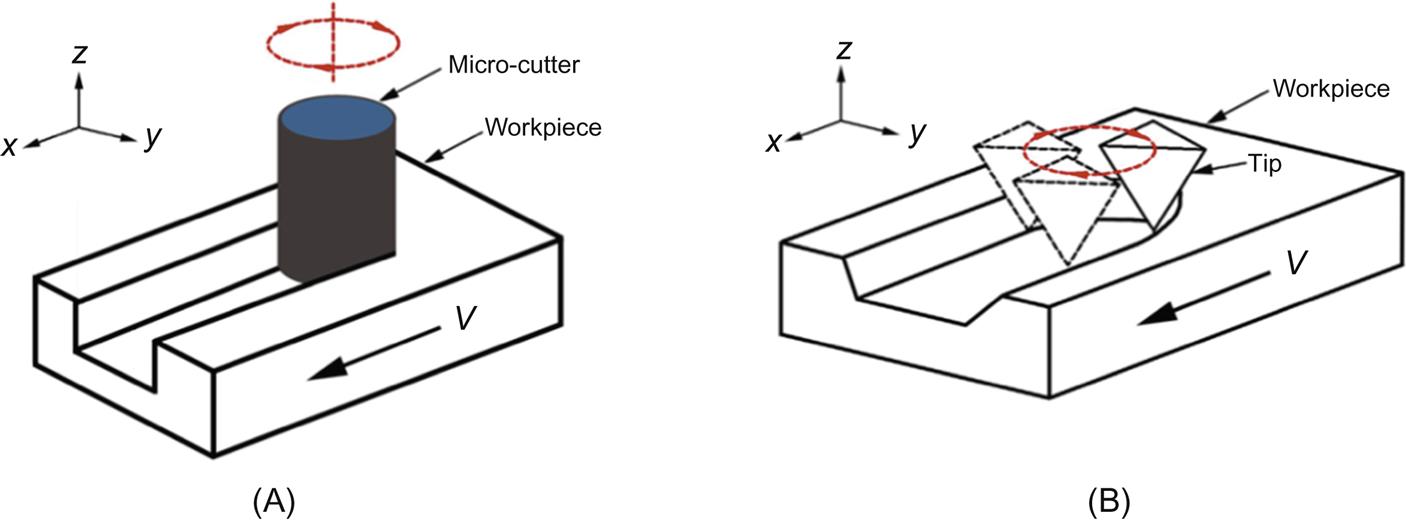
Figs. 3.1A and B show the schematic of the micromilling process and the tip’s orbital motion based the micromachining process, respectively. The pyramidal tip is used as the example. The symbol V and the arrow represent the moving direction of the workpiece during machining. The micromilling process in Fig. 3.1A, shows the microcutter rotating around its center, usually driven by a high speed spindle. The section of the microchannel machined by this process is a rectangle. The width of the channel is determined by the diameter of the microcutter used. As shown in Fig. 3.1B, the pyramidal diamond tip revolves around an orbital center. This motion is realized by a 3D nanopositioning stage in this study, which will be explained in the next section. The section of the microchannel machined by this method is trapezoidal and influenced by the diamond tip shape. The width of the channel is basically determined by the radius of the orbital motion. The radius is changed according to the moving range of the nanopositioning stage. But for the micromilling process, it is impossible to machine the channel with a width less than the diameter of the microcutter. The relative motion between the tool and the workpiece in three dimensions can be realized in the same way with the conventional micromilling process. The coarse moving stages can be used. The main difference between the micromilling process and the orbital motion based micromachining process is that no high speed and high accuracy air bearing spindle is employed in the latter condition.
3.3 Micromachining setup and test of the stage’s trajectory
3.3.1 Establishment of the micromachining setup and the machining procedure
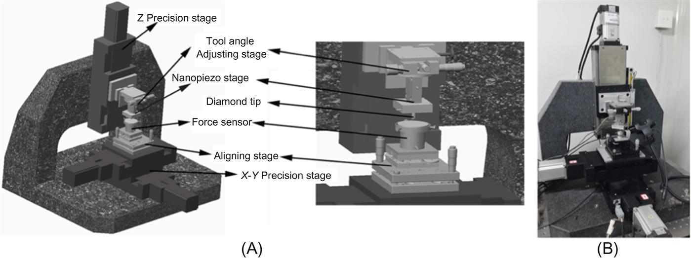
Figs. 3.2A and B show the schematic and photo of the micromachining setup based on the orbital motion of the tip. The system parts mainly consist of: a nanopiezo stage; X-, Y-, and Z- precision stages; the diamond tip; the aligning stage; and a force sensor. The details of each part are described as follows.
1. Nanopiezo stage. In order to make the tip move in three directions, the piezo is used as the driver, and the flexible hinge is used as the guide for the nanostage. The resistance strain gauge sensor is used to measure the displacement as the feedback signal. In this study, this stage (XP-611.XYZ) is provided by Xin Ming Tian Science and Technology Co., Ltd. China. The open-loop and close-loop travels are 120 and 100 μm, respectively. The resolution is 4 nm. The unloaded resonant frequencies in the, X, Y, and Z axis are 350, 220, and 250 Hz, respectively. This stage is driven by a controller through a NI USB-6259.
2. X-Y-Z precision stage. It includes X-, Y-, and Z-stage which are driven by the servo motors with the encoder to measure the displacement as the feedback signal. Its moving range is 100 mm×100 mm×100 mm. The repeatability is 5 μm. The resolution is 1 μm, and the maximum moving velocity is 40 mm/s. This part is provided by the Beijing Micro/Nano Optical Instrument Co., Ltd. China.
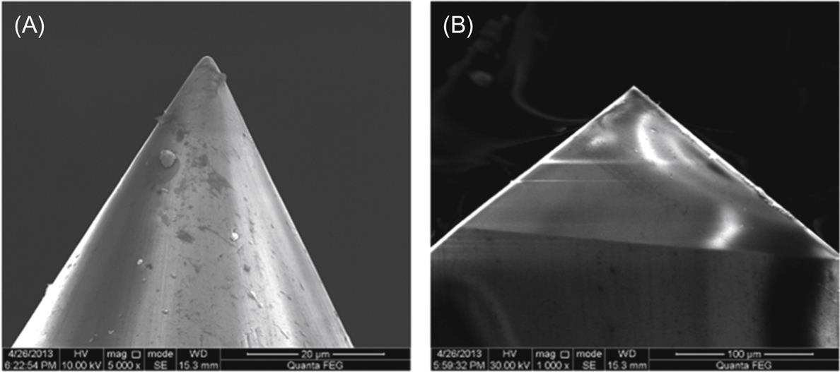
3. Diamond tip. The pyramidal and conical diamond tips are bought from the Synton-MDP company, Switzerland. The pyramidal tip is the cube corner nanoindentation tip with the face angle of 35.26°. The cone angle of the conical tip is 60°, and the tip radius is less than 1 μm. The SEM images of the used tips are presented in Fig. 3.3.
4. Aligning stages. In this system, as shown in Fig. 3.2A, there are two different aligning stages: one is the aligning stage for sample leveling and the other is for the tool angle adjusting stage, to change the cutting angle when using the pyramidal diamond tip. Both are adjusted by the precision screw. The aligning stage has two freedoms, and the moving range is less than ±3°. The tool angle adjusting stage uses the rolling guide with the minimum reading of 55.8″ within the range of 360°.
5. Force sensor. The force sensor is employed to measure the cutting forces. The other function of the force sensor is to level the sample surface with the aligning stage by measuring the contact forces at different locations. It is manufactured by the ATI company of USA. The model is Nano17 Ti. The measurement ranges in X and Y directions are ±8N. The range in Z direction is ±14.1N. The natural frequency is 3 KHz.
The micromachining procedure based on this setup is described as:
1. The sample is adjusted by the aligning stage to make the sample surface parallel to the horizontal plane. The aligning method is to guide the diamond tip to the sample surface with a fixed normal force, measured by the force sensor at three different locations. Simultaneously, the coordinates of the diamond tip in the Z direction are recognized by the nanopiezo stage. By adjusting the screw of the aligning stage, the coordinates of three points in the Z direction are almost the same values. Then the sample’s inclination is successfully adjusted.
2. The tool angle adjusting stage changes the edge direction of the pyramidal diamond tip to achieve a better removal state. It is no need of adjusting if the conical tip is used. Then the diamond tip is driven by the nanopiezo stage with the required frequency, and the moving range is in the X-Y directions.
3. The Z precision stage brings the nanopiezo stage to approach the sample surface within the distance of 50 μm. After that, the nanopiezo stage in the Z direction brings the diamond tip to contact the sample surface by monitoring the force sensor’s signal and then controls the machined depth by moving the diamond tip future.
4. Finally, the X-Y precision stage moves the sample to perform the micromachining process, and the required microstructures will be obtained.
3.3.2 Test of the trajectory of the nanopiezo stage in the orbital motion
For controlling the orbital motion of the diamond tip, it is very important to know the performance of the nanopiezo stage. In this study, the moving trajectories of the nanopiezo stage in the unload and load states are characterised respectively.
As shown in Fig. 3.4A, the nanopiezo stage is put in an upward position and brings the polymer (polymethyl methacrylate, PMMA) plate to carry out the orbital motion. This setup is then placed under a commercial AFM head (Q-Scope250 of Ambios Company, USA). The AFM tip applies a normal load of several micro Newtons. It is enough to scratch a nanogroove on the PMMA plate. By inspecting the scratched groove, we can find the performance of the nanopiezo stage with different moving ranges and frequencies. Under this condition, the nanopiezo stage drives the sample rather than the diamond tip and no real cutting forces are applied on it. Therefore, we called this state as “the unload state.”
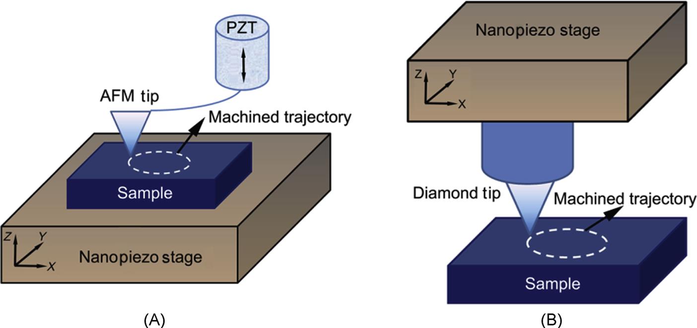
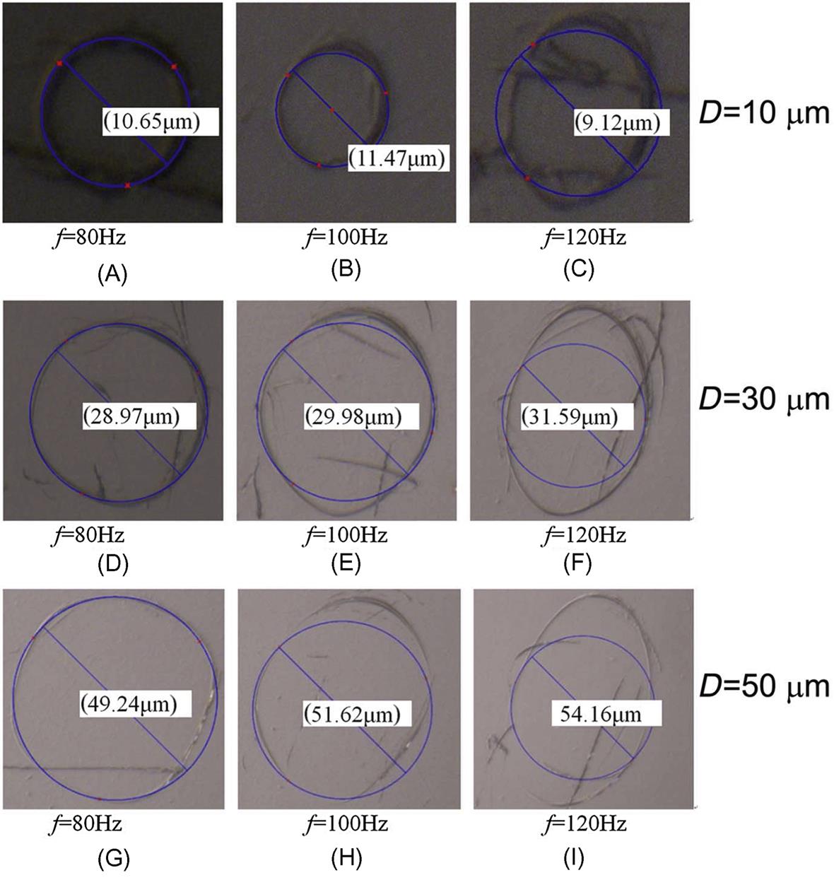
Fig. 3.5 shows the trajectories of the stage with the diameters of 10, 30, and 50 μm and the frequencies of 80, 100, and 120 Hz. In this test, AFM works in the contact mode. The normal load is about 10 μN. Under this condition, the obvious scratches can be found on the PMMA surface. From the figure, for all of the diameters, the trajectory is perfect for the frequency of 80 Hz (Figs. 3.5A, D, and G). With the same diameter, using the lower frequency is confirmed to lead to the same conclusions by more tests. When the frequency is larger than 80 Hz (e.g., 100 Hz in Figs. 3.5B, E, and H), the circular trajectory tends to be an ellipse. With the increase of the frequency, the scratched grooves can hardly be formed on the sample surface, and the trajectories are more of a mess (Figs. 3.5C, F, and I). The reason is due to the resonance frequency of the stage and the load of the stage induced by the sample weight. Moreover, a larger moving range corresponds to a lower frequency. Since the nanopiezo stage works in the open-loop state, all of the diameters are larger than the setting values that are listed on the right row of the figure. Based on the above tests, the maximum frequency of 80 Hz and the maximum diameter of 50 μm are the good values in the unload state.
As shown in Fig. 3.4B, the nanopiezo stage is placed as it works and drives the diamond tip to carry out the orbital motion. Without the motions of the sample in the X-Y directions, the diamond tip only scratches a circle on the PMMA surface. This circle trajectory can reveal the performance of the Nanopiezo Stage with different moving ranges and the frequencies in the real machining process. Under this condition, the nanopiezo stage directly drives the diamond tip, and the real cutting forces are applied on it. Thus, we called this state as “the load state.”
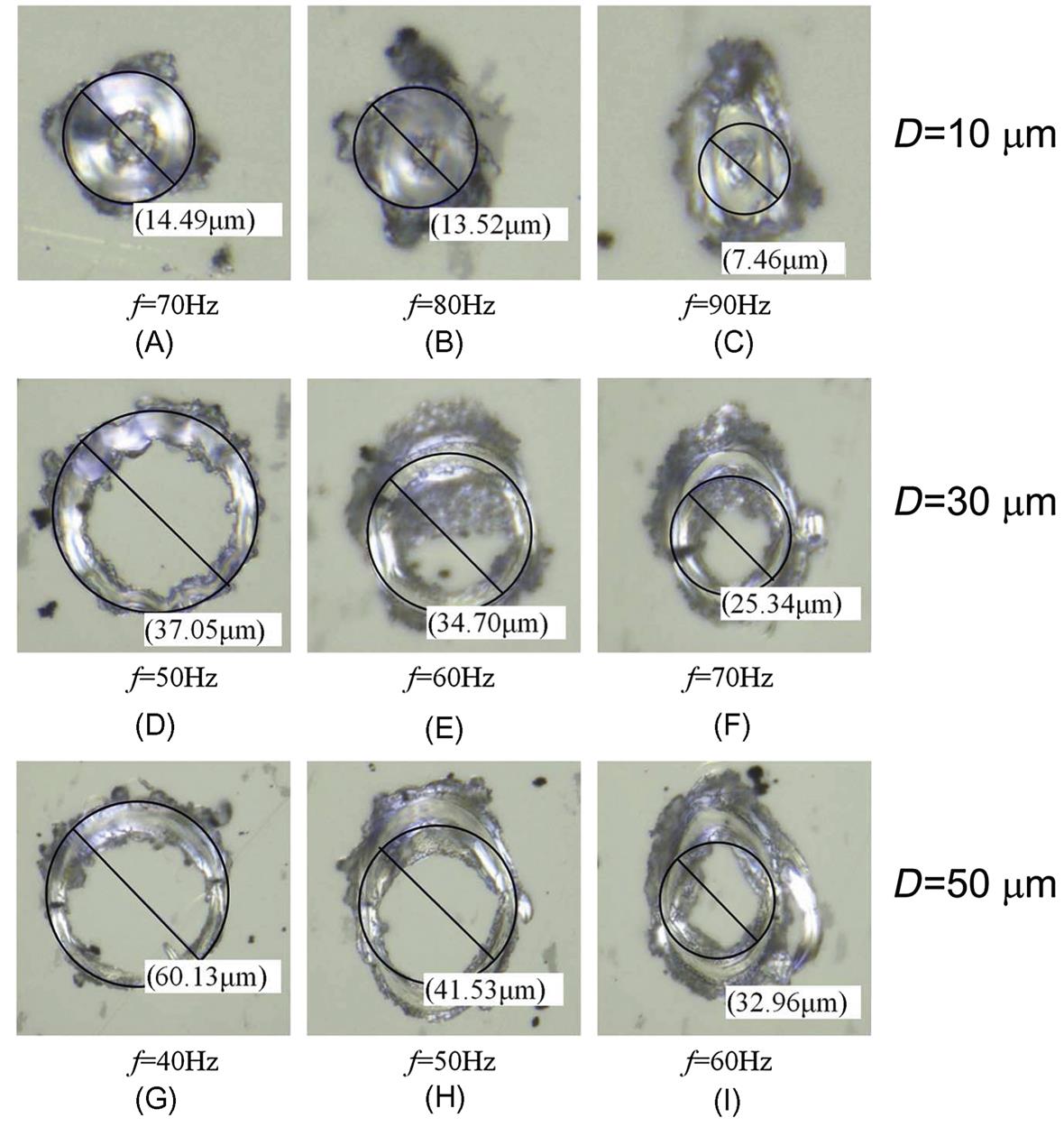
Fig. 3.6 shows the trajectories of the diamond tip with the diameters of 10, 30, and 50 μm and the frequencies of 40–90 Hz. In these tests, the conical diamond tip is used, owing to the easy observation of the trajectory and elimination of the tip geometry effect. The machined depth is about 1 μm. When the diameter is 10 μm (Figs. 3.6A, B, and C), an increase in the frequency leads to a bad trajectory shape. When the frequency is larger than 80 Hz, the circular groove changes to the ellipse groove. Under this condition, 70 Hz is the critical value to achieve a better result. It is the difference between the diameter of 14.49 μm in Fig. 3.6A and the setting value of 10 μm. The reason is because the measured trajectory shown in Fig. 3.6A is the envelope of the outer edge of the conical tip. It is the same condition for other tests in Fig. 3.6. For the diameter of 30 μm (Figs. 3.6D, E, and F), the critical frequency is 50 Hz. For the diameter of 50 μm (Figs. 3.6G, H, and I), the critical frequency is 40 Hz. Because under this condition, the real load is applied on the tip, and all the critical frequencies lower than 80 Hz are used in the unload state. All these critical frequencies are obtained with the machined depth of 1 μm. Results from more tests show that, with a larger machined depth of less than 4 μm, the frequency of 10 Hz is feasible for most machining conditions based on our system. Actually, such low frequency will lead to a low machining efficiency.
3.4 Micromachining mechanism using the orbital motion of the tip
3.4.1 Comparison of chip states with the conical and pyramidal tips
The pyramidal and conical diamond tips are two common tips which can be purchased from many manufacturers of the nanoindenaion device. The pyramdial diamond tip has three edges. It may be more suitable to be used as a cutting tool; although, the conical tip has already been used to perform the micromachining process (Heamawatanachai & Bamberg, 2009). The following tests are carried out to clarify which one is better.
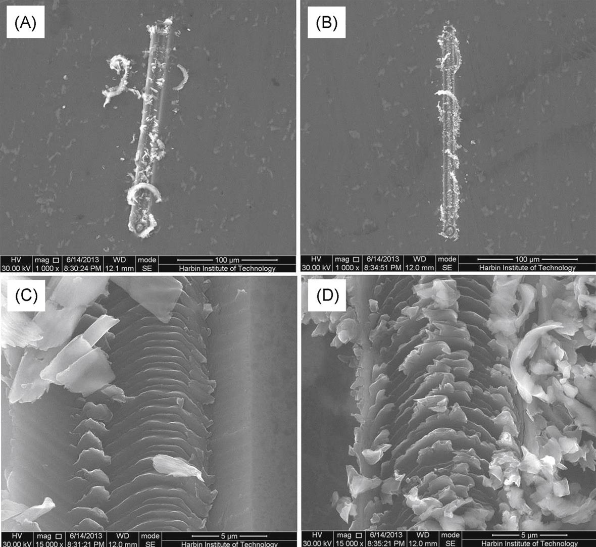
Using two kinds of tips, the microchannels are machined as shown in Fig. 3.7. The diameter of the tip motion is 10 μm. The frequency of the nanopiezo stage is 30 Hz. The machined depth is 1 μm. The machining velocity of the precision stage is 15 μm/s. The length of the channel is 200 μm. The sample material is aluminum alloy (2024). Figs. 3.7A and C are the SEM images of the channel and its local enlarged part, using the pyramidal diamond tip, respectively. Figs. 3.7B and D are the SEM images of the channel and its local enlarged part, using the conical diamond tip, respectively. From the figure, the following conclusions are obtained. For the pyramidal diamond tip, the long belt-type chips are achieved, indicating that the materials are efficiently removed. Thus, little burrs are found on both edges and the bottom of the channels. For the conical diamond tip, on the contrary, large amount of burrs are formed at both sides and the bottom of the groove. Few belt-type chips are formed. The difference is mainly due to the real cutting angle during the orbital motion of the tip. Actually, the conical diamond tip is suitable for the machining of brittle materials because of the large negative rake angle during machining. In this study, we mainly focus on the machining mechanism with the pyramidal diamond tip.
3.4.2 Difference between the micromilling process and this technique
As metioned in Section 3.2 in the miromilling process, the microcutter rotates with a center. In the tip orbital motion based micromachining process, the tip revolves, and the relative position between the tip and the workpiece changes with the revolution. Fig. 3.8 shows the schematics of two machining processes.
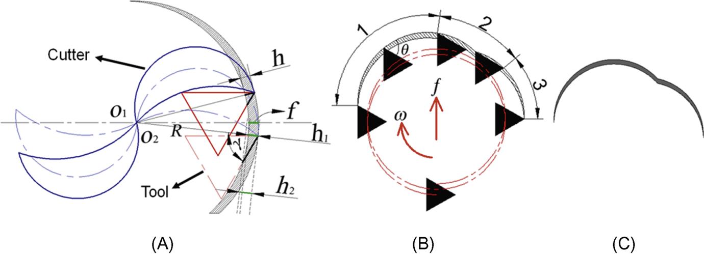
In Fig. 3.8A, the solid and dotted lines represent the original and new positions of the cutter in the micromilling process. The shadow part shows the removed materials. In the milling process, because the rake face of the cutter is a curved surface and it rotates around the point O, the rake angle is constant. With the feed of the tool, the uncut chip thickness (h) changes from zero to the maximum value and back to the zero for each edge of the cutter. For the following machining tests, the state is theoretically kept the same. In Fig. 3.8A, the solid and dotted triangles show the original and new positions of the pyramidal diamond tip, respectively. In the micromachining process, the rake angle (γ) changes with the revolution of the tip, and the uncut chip thickness varies according to different postions of the tip presented by the h2. This process is different from the micromilling process. Fig. 3.8B shows the details of one condition of the relationship between the tip orientation and the feeding direction, in the machining process of one revolution of the pyramidal diamond tip. The term, f, shows the feeding direction and ω shows the revolving direction. In one revolving cutting process, there are three kinds of states: single-edge cutting, Courses 1 and 3, and double-edge cutting, Course 2. The solid dark triangle shows the position of the diamond tip. It can be found that the length of the Course 1 is the longest, and that of the Course 3 is the shortest. Because two cutting edges would together join in the machining process, Course 2 is more complex than Courses 1 and 2. For Course 1 and 2, with the movement of the diamond tip, the rake angle (γ) and the uncut chip thickness are constantly changing. For Course 3, the rake angle (θ) is positive and changing with the tip revolution. The shape of the prescribed removed material is presented in Fig. 3.8C, which is different from the shadow part of the milling process shown in Fig. 3.8A. The tip orbital motion based micromachining is more complex. More processing experiments should be carried out to find out the influencing factors of this process.
3.4.3 Determination of the uncut chip thickness and the cutting rake angle
In order to understand the machining emchanism, the uncut chip thickness and the cutting rake angle of the tip orbital motion based micromachining should be achieved. The cutting process of the tip edge is looked on as an oblique cutting with a varied cutting rake angle, and while the tip is revolving, two or three cutting edges would participate in the cutting process. This is a complicated cutting process. For simplifying this process, a two-dimensional (2D) cutting plane as shown in Fig. 3.8A is used to calculate the uncut chip thickness and the cutting rake angle.
(3.1)
(3.2)
Fig. 3.9 shows the geometric relationship for calculation of the uncut chip thickness and the cutting rake angle in the milling process. Due to a fixed cutting rake angle, when the tool turns to the angle θ2, the corresponding uncut chip thickness (h) can be calculated by the analytical method according to the Eqs. (3.1) and (3.2). However, in the machining process of the tip orbital motion, owing to the tip translantion movement of the revolution, the cutting rake angle continuously varies, and hence the uncut chip thickness is different from that in the milling process, especially for the pyramidal tip. As shown in Fig. 3.8A, when the center of the revolution arrives at the position O2, the uncut chip thickness, based on the milling process, is represented by h2, which is the distance between the intersection of the moving radius (R) and the machined surface, and the intersection of the moving radius and the unmachined surface. The amount of the feed per circle (f) is also the maximum thickness in the milling process. The actual amount of the uncut chip thickness in the tip-based trajectory machining is h2 which is the vertical distance between a pair of parallel lines along the instantaneous velocity direction, passing through the intersection of the rake face, the machined surface, and the tip edge apex. It can be seen that at this position owing to the effect of the negative cutting rake angle (γ), h2 is different from h1 and has exceeded f. In addition, at the position O1, the difference between the uncut chip thicknesses is relatively small. Therefore, the analytical method used for calculating the uncut chip thickness in the milling process is not applicable, while the numerical calculation is employed. The variation of the cutting rake angle γ during single edge cutting processes (Courses 1 and 3) is calculated by using θ (the angle between the tip’s rake face and the unmachined workpiece surface) minus 90°. Course 1 and 3 in the Fig. 3.8B are mainly studied because they are not only single edge cutting processes, but also are used to machine two sides of channel.

Fig. 3.10 shows the relationships between the tip revolution angle, the uncut chip thickness, and the cutting rake angle of the trajectory presented in Fig. 3.8B. The dotted line represents the uncut chip thickness of the conventional milling process. The solid and broken lines show the uncut chip thickness and the cutting rake angle for Courses 1 and 3, respectively. The processing parameters are: a 0.4 μm feed mount per revolution, 10 μm diameter of the revolution motion, 1.2 μm machined depth, and the triangle side length is 3 μm, correspondingly. The machining process is presented in Fig. 3.4B.
• The cutting rake angle. For Course 1, the cutting rake angle decreases from 30° to −70°, with the increase in the tip revolution angle. At the beginning of the cutting process, the tip edge cuts into the sample surface, and a positive rake angle is achieved with the tip revolution angle from 0° to 100°. For Course 3, the cutting rake angle also decreases from 15° to −30°, with the increase in the tip revolution angle. When the tip leaves from the machined structure, the maximum rake angle of −30° is presented. As mentioned above, this property is different from the conventional micromilling process, during which the rake angle is a fixed value. In generally, for plastic workpiece materials, such as aluminum, a positive rake angle is prone to lead to the cutting state and effectively remove the materials, and a negative rake angle will result in the pileup of the removed materials, forming different kinds of burrs. Therefore, based on the above analysis, using the trajectory shown in Fig. 3.8B, the microgroove with a smooth left side and a pileup, or burrs, on the right side can be obtained. This will be discussed in the following section.
• The uncut chip thickness. When the tip revolution angle varies from 0° to 40° and from 140° to 180°, the uncut chip thickness has little difference with that of the milling process. The uncut chip thickness increases with the tip revolution angle when it is less than 100° in Course 1. The maximum value, 0.55 μm, is larger than the feed mount per revolution of 0.4 μm. Under this condition, a negative rake angle is used.

As shown in Fig. 3.10B, when the tip revolution angle varies from 0° to around 30°, the cutting rake angle is positive, and the material is removed mainly in way of chips. After that, when the tip revolution angle changes from 30° to 100°, the rake angle becomes negative, and the uncut chip thickness is larger. Under this condition, the materials are mainly deformed by ploughing and are not prone to be removed. When the tip revolution angle is within the scope of 100°–140°, two cutting edges together join in the machining process which is a complicated cutting process and can not be expressed by cutting raka angle and uncut chip thickness, and hence the rake angle and the uncut chip thickness are not provided here. Under this condition, ploughing and extrusion are estimated to play the key roles as Course 2 shown in Fig. 3.8B. In the Fig. 3.10B, in the process from point 2 to 3, the belt chips are piled up. When the tip revolution angle changes from 140° to 180°, although the uncut chip thickness becomes small, the rake angle makes the materials to be removed more in type of the chips, which are pushed to the position of point 4. Fig. 3.10B shows one complete circle of machining. When the micromachining process is carried out with a feed, only the tip revolution angle from 0° to 180° is employed.
3.5 Formation mechanism and control methods of burrs
In this section, the burrs formed during machining channels, based on the orbital motion of the tip, are mainly studied on the material of Al. The types of burrs are classified by analyzing their morphologies and sizes. By comparing channels machined, respectively, by the conical tip and the pyramidal tip, the optimal machining way is proposed. Meanwhile, by optimizing the machining process and the deburring process, channels with smooth sides are obtained.
3.5.1 Burr formation during machining with the conical tip
Due to the symmetry of the conical tip along different feeding directions, the machining trajectories are the same. Therefore, the effects of feeding directions on machining channels are neglected. Fig. 3.11 shows the AFM images of the channels machined by the conical tip with different feed rates (Fig. 3.11A 2 μm/s and (B) 10 μm/s). The machined depth is set to 1.5 μm for all tests. In two conditions, burrs formed on both sides of the channel; and under the high feed rate condition, burrs are more serious, which is attributed to the increase of the uncut chip thickness. In Fig. 3.11A the burr on the left side (the upmilling side) is formed by the plastic deformation of materials and is larger than that at the right side (the downmilling side). At the upmilling side, the uncut chip thickness begins to increase at the zero value, owing to the influence of the circular cutting edge. There will not be chips formed until the tip revolves to a certain angle, achieving the minimum chip thickness; and hence, before forming the chip, the materials are violently extruded by the tip face forming the burr. At the downmilling side, though the uncut chip thickness decreases back to zero from the maximum value, the chip is formed with the revolving tip; and hence, the caused plastic deformation is relatively small. In the case of high feed rate in Fig. 3.11B, owing to the increase of the uncut chip thickness in each revolution, before achieving the minimum chip thickness the angle needed to revolve of the tip during each circle is decreased, which results in less extrusion between the tip face and the machined material. The burr at the upmilling side is similar to that in the milling process (De Assis, Jasinevicius, & Rodrigues, 2015) that has a wave-like shape at the channel’s top. It is due to the fracture of the materials, and they are pushed by the tip to the side’s top. At the right side, the burr is the residual material that is unremoved by the revolving motion. It can be found that in two feed rates there are both burrs formed at the channel’s top, which are difficult to be removed by postprocessing.

3.5.2 Burr formation during machining with the pyramidal tip
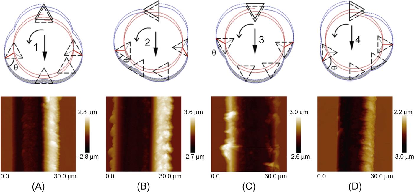
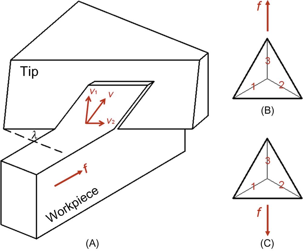
Different from the symmetry shape of the conical tip, along different feeding directions, the machining trajectories of the pyramidal tip are different. Because of the triangular section of the pyramidal tip, with the circular revolution there are main four kinds of machining trajectories as show in Fig. 3.12, and each machining trajectory corresponds to a type of channel. It can be seen that in Figs. 3.12B and C, there are burrs formed on both sides of the channels; while in Figs. 3.12A and D, burrs are only formed on the downmilling side, and the upmilling side is smooth. In the figure, the lines through the centers of the triangles are the moving trajectories of the tip, and the lines through the apexes of the triangles are the machining trajectories along different directions. The shaded areas are the uncut chip thicknesses in each revolving cut. The θ is the angle between the tip rake face and the machining trajectory, which corresponds to the cutting rake angle. The differences of the machined channels and formation mechanisms of burrs are due to the variations of the uncut chip thickness and the cutting rake angle, which was studied in detail during the previous study (Xue et al., 2015). However, there is another important factor for deciding the positions of burrs—the cutting edge inclination angle. Owing to the pyramidal shape of the tip, there would be an inclination angel (λ) existing during the tip’s cutting processing, and hence, the tip’s cutting can be looked on as the oblique cutting as shown in Fig. 3.13A. In the oblique cutting process, the chip flow is not along the direction perpendicular to the cutting edge (V1) but along the resultant direction (V), added with a velocity component tangential to the cutting edge (V2). However, with different feeding directions and the tip’s edges, the directions of the velocity component (V2) would be different (upward or downward). For instance, in Fig. 3.13B, when the tip feeds forward along the arrow direction, the V2 of the edges one and two are both upward and the edge three does not participate in cutting. In Fig. 3.13C, the V2 of the edges one and two are both downward. During the tip’s revolving cut, the direction of V2 decides the flow direction of the chip. It can be judged, that along the tip’s moving direction, if the tip apex is in front of the cutting edge, the V2 is upward; if the tip apex is in the back of the cutting edge, the V2 is downward. At the right sides of Figs. 3.12A, B, and D, the burr formation results from the accumulated chips. However, at the right sides of Figs. 3.12A and B, the cutting edges (marked in bold) cause the upward V2, and hence the produced chips flow upward to the channel’s top. In Fig. 3.12D the cutting edge at the right side approximately does not have the component of V2, which can be seen as an orthogonal cutting, and hence the chips would turn laterally pushed by the tip and attached on the channel’s sidewall, which is the condition that the burr can be easily removed.
3.5.3 Methods of formation of slight burrs
From the above analysis, it can be known that the orbital motion of the pyramidal tip is more feasible to machine better channel structures. Meanwhile, the burr in the machining process of Fig. 3.12D is the accumulated chip attached to the channel’s sidewall, and hence, it is more useful to optimize this process.
First, the strategy of the second feed is conducted to remove the burr at the sidewall as shown in Fig. 3.14A. According to the study (Xue et al., 2015), the feed rate was set to 4 μm/s. The burr caused by the plastic deformation of the materials can be suppressed. Based on this tip’s orientation and the revolving direction after the second feed, the burrs are effectively removed, and channels with two smooth sides are obtained. The pit is milled through the row-by-row procedure based on this channel machining process, as shown in Fig. 3.14B. The burr is mainly accumulated at one side of the pit, and the other three sides are smooth. Meanwhile, the bottom surface quality of the pit (marked in bold) is measured. The roughness, Ra and Rq, are 34.2 and 43.4 nm, respectively.

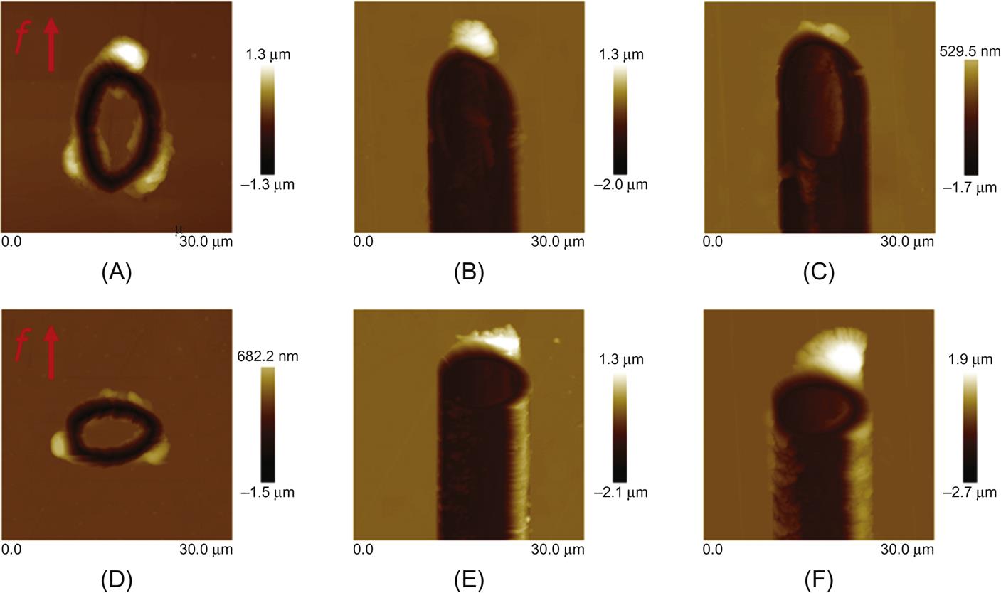
Second, different tip’s trajectories can be used to reduce the burr. In the traditional milling process, owing to the limitation of the rotation of the spindle, the cutting edge of the mill can only do the spiral movement based on a circle. However, the orbital motion of the tip is based on the resultant motion of the translation of each axis, which is unable to change the tip posture and exhibits a high flexibility. When the x- and y-axes do the simple harmonic motions with the same amplitude, frequency, and out of phase, the trajectory is the circle similar to the milling condition. However, if the amplitudes of two axes are different with other parameters unchanged, the trajectories are the ellipses, which is unable to be conducted in the milling process. Therefore, this is the advantage of the orbital motion machining. When the elliptical trajectory is used, the variations of the uncut chip thickness and cutting rake angle are different from those in the circle trajectory (Yan, Geng, & Hu, 2015). A shape elliptical trajectory and a flat elliptical trajectory are designed as shown in Figs. 3.15A and B. For the shape ellipse, the long axis (along the feeding direction) is 7 μm in length, and the short axis is 5 μm. For the flat ellipse, the long axis is 5 μm, and the short axis (the feeding direction) is 3 μm. This is because the if the channel’s width is same, the chip volume in each revolution is made the same. It can be seen that both channels in Figs. 3.15B and C (feed rates are 2 and 4 μm/s, respectively), machined by the shape ellipse, have two smooth sides. However, under the flat ellipse condition, the burr at the right side has not been removed, and the burr size increases as the feed rate increases. Because of the tapered shape of the tip, some materials are unremoved to remain at the channel’s bottom (Yan, Geng, et al., 2015). In Fig. 3.15F, the left side has been undermined by the residual materials at the bottom, which is due to a larger uncut chip thickness of the flat ellipse in each revolution, causing more residual materials. Meanwhile, comparing Fig. 3.15B with Fig. 3.15C, the lower feed rate results in the smaller variation of the uncut chip thickness, which makes the channel’s bottom quality better.
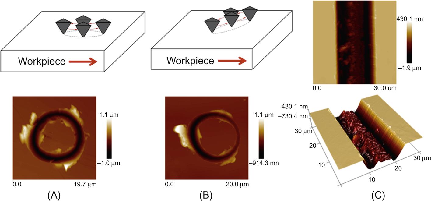
Third, except for approaching the workpiece surface, the z-axis can also be employed to provide the moving trajectory for the tip, which is used as a deburring method for the channel. By making the z-axis do the simple harmonic motion, accompanying the resultant motion of x- and y-axes, the tip can achieve a 3D movement. Fig. 3.16A is the 2D motion in the horizontal plane, in which the machined channel is presented in Fig. 3.12D. Fig. 3.16B is the 3D motion in space by introducing the z-axis motion based on the Fig. 3.16A. The altitude difference is about 500 nm along the feeding direction. According to the schematic of Fig. 3.16B, the channel was machined by once feed with the feed rate of 4 μm/s as shown in Fig. 3.16C. It can be seen that by using this 3D trajectory, the burr at the right side has been successfully removed, and the machined channel has two smooth sides, which confirms that this approach is a good deburring method. In addition, owing to once feed, there is the trimming process for channel’s bottom compared to the condition of twice feeds, which makes the bottom quality worse than that in Fig. 3.14A. Reducing the feed rate can also improve the bottom quality.
3.6 Effects of the processing parameters and fabrication of microstructures
3.6.1 Effects of the processing parameters on machining microchannels
In this section, effects of the processing parameters including the revolving frequency, feed rate per revolution, diameter of the tip’s circular moving trajectory, and the machined depth on the surface roughness (Ra) are studied. Ra of 30 μm×6 μm area at the bottom of the machined channel is measured by AFM. As shown in Fig. 3.17, A=30 and B=6 μm. The sample material is the Aluminum alloy (2024) machined by the ultra-precision turning, with the original surface roughness (Ra) of 5 nm. The conical diamond tip is employed in this process. The detail settings for these processing parameters and the corresponding measured Ra are listed in Table 3.1. The revolving frequency changes from 10 to 40 Hz. The feed rate per revolution changes from 0.2 to 2 μm. The diameter of the tip’s circular moving trajectory changes from 10 to 50 μm. The machined depth changes from 0.5 to 3 μm. The relationships between these processing parameters and Ra are plotted in Fig. 3.18.

Table 3.1
The detail settings of the processing parameters and the surface roughness Ra
| No | Revolving frequency f(Hz) | Feed rate per revolution a(μm) | Diameter of the tip’s circular moving trajectory D(μm) | Machined depth h(μm) | Surface roughness Ra(nm) |
| 1 | 10 | 1 | 10 | 1 | 101.3 |
| 2 | 20 | 1 | 10 | 1 | 165 |
| 3 | 25 | 1 | 10 | 1 | 150.9 |
| 4 | 30 | 1 | 10 | 1 | 172.1 |
| 5 | 40 | 1 | 10 | 1 | 292 |
| 6 | 20 | 0.2 | 10 | 1 | 103.5 |
| 7 | 20 | 0.5 | 10 | 1 | 169 |
| 8 | 20 | 1 | 10 | 1 | 237 |
| 9 | 20 | 1.5 | 10 | 1 | 270.6 |
| 10 | 20 | 2 | 10 | 1 | 293.8 |
| 11 | 20 | 1 | 10 | 1 | 165 |
| 12 | 20 | 1 | 20 | 1 | 189.3 |
| 13 | 20 | 1 | 30 | 1 | 180.6 |
| 14 | 20 | 1 | 40 | 1 | 209 |
| 15 | 20 | 1 | 50 | 1 | 355 |
| 16 | 20 | 1 | 10 | 0.5 | 296.1 |
| 17 | 20 | 1 | 10 | 1 | 317 |
| 18 | 20 | 1 | 10 | 1.5 | 370 |
| 19 | 20 | 1 | 10 | 2 | 378.9 |
| 20 | 20 | 1 | 10 | 3 | 454 |
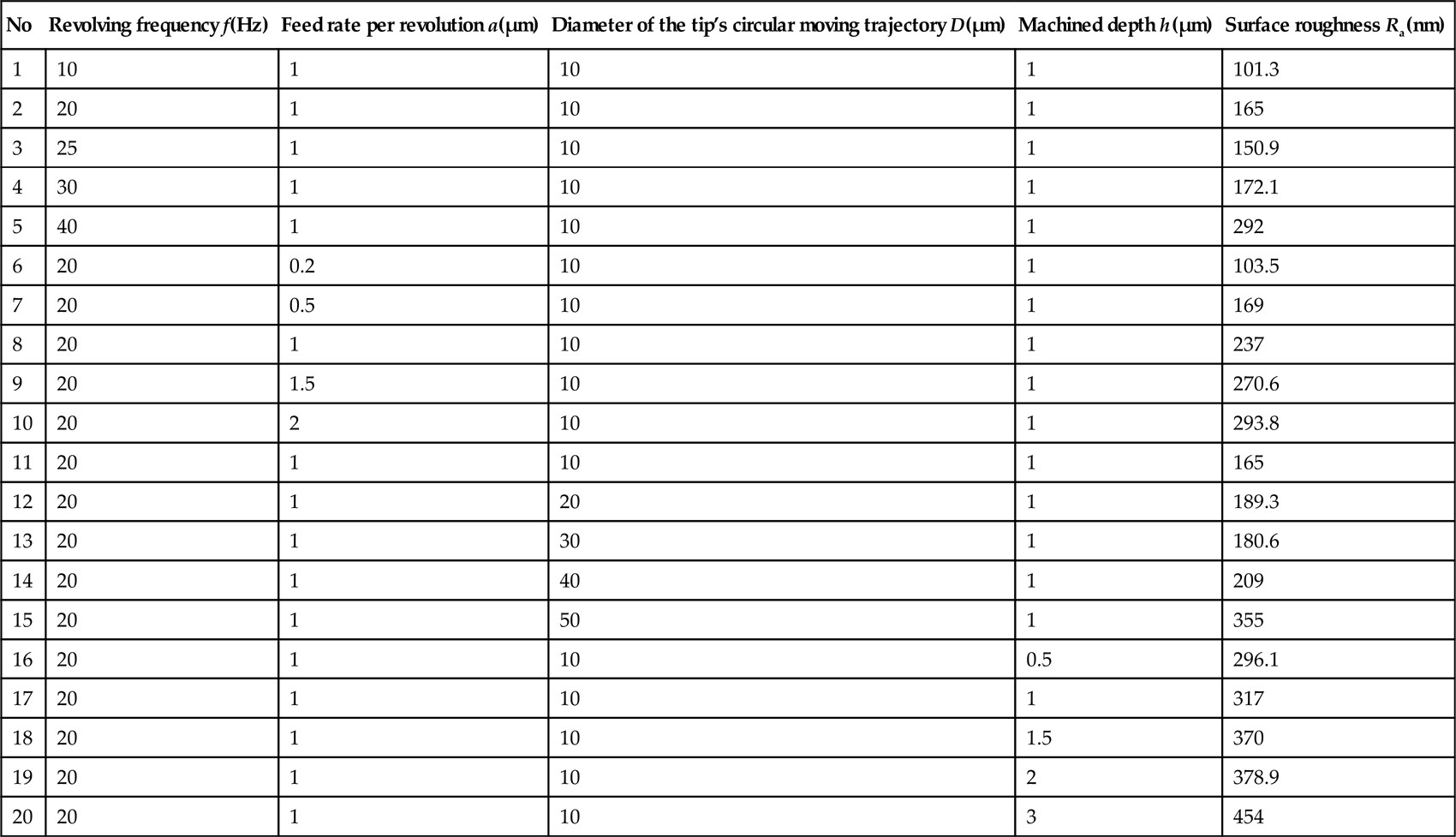
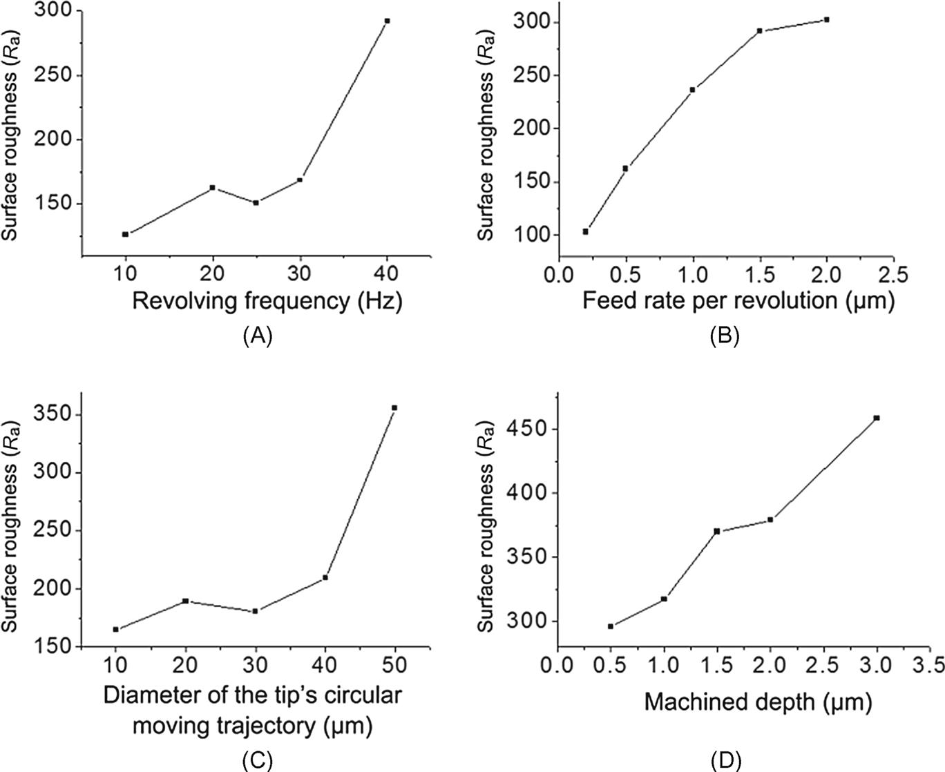
As shown in Fig. 3.18A, when the revolving frequency is less than 30 Hz, Ra changes a little. When it is larger than 30 Hz, Ra abruptly increases. This value is far less than the value of 70–80 Hz presented in Fig. 3.6A. Higher frequency will bring more vibrations of the stage into the machining process. Therefore, a lower frequency is better for the higher surface quality. However, it will lead to the low machining efficiency. As shown in Fig. 3.18B, Ra increases with the feed rate per revolution and will reach to the saturation state when it is larger than 1.5 μm. A feed that is too large rate leads to more residual tracks, owing to the limited radius of the diamond tip as shown in Fig. 3.7. As shown in Fig. 3.18C, when the diameter of the tip’s circular moving trajectory is less than 30 μm, the surface roughness (Ra) varies a little. When it is larger than 30 μm, Ra abruptly increases. With the fixed revolving frequency of 20 Hz provided in Table 3.1, a larger diameter will lead to the instability of the nanopiezo stage, which results in a bad surface quality. As shown in Fig. 3.18D, Ra increases with the machined depth. The large cutting forces induced by the large machined depths lead to the large deformations of the materials. Then the surface quality will become worse.
Therefore, in order to get a smooth machined surface, the processing parameters are: the revolving frequency is 10 Hz, the feed rate per revolution is less than 1 μm, the diameter of the tip’s circular moving trajectory is 10 μm, and the machined depth is 1 μm. These optimal parameters do also work in the condition of the pyramidal tip.
3.6.2 Effect of the feed on machining microstructures
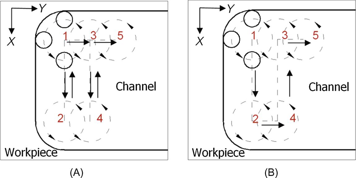
Using this technique, it is very easy to machine a required microchannel (e.g., a channel with 10 μm in width). But if it is desired to machine large scale microstructures this way, the other feed (in Y axis) perpendicular to the feed direction X as presented in Fig. 3.1B is needed. In this work, we provided two approaches to realize 2D microstructures for getting better surface quality, as shown in Fig. 3.19. The dotted circles and the sequence numbers of one, two, three, four, and five show the tip’s position during the machining process. The arrows show the tip’s moving direction. Fig. 3.19A shows the reciprocal feed mode. Point 1 shows the original position of the tip. First, the tip moves from the point 1 to the point 2 and then returns to the point 1 along the same trace. Second, the tip goes to the point 3 with a feed. Next, the tip continues to go to the point 4 and then return to the point 3. All the grooves are machined twice. Fig. 3.19B shows the side feed mode. First, the tip moves from the point 1 to the point 2 and then moves to the point 4 with a feed. Second, it continues to move to the point 3 and then feeds to the point 5. During this process, each groove is machined for only once. For both conditions, the width of the required microchannel is determined by the length of each machining in the X direction, and the length is obtained by the feed multiplied by the number of the feed in the Y direction. From the machining processes presented in Fig. 3.19, it can be found that the tip shape will play a key role in the machined surface quality. In the present study, a symmetrical conical diamond tip and an unsymmetrical pyramidal diamond tip are both used in the machining processes. Therefore, effects of two kinds of tips are studied as follows.
In order to study the effects of different modes and shapes of the tip on the surface quality, the following tests are carried out using the machining parameters: the revolving frequency is 10 Hz, the diameter of the tip’s circular moving trajectory is 10 μm, and the machined depth is 1 μm. The feed rate per revolution is 1.0, 2, 3, 4, 5, and 6 μm. The conical and pyramidal diamond tips are employed. The surface roughness (Ra) data are obtained from the area 20 μm×20 μm from the machined channels by AFM.
Figs. 3.20A and B show the relationships between the feed (f) and Ra, with the side feed mode and the reciprocal feed mode and using the conical diamond tip, respectively. When the feed is 1 μm in both modes, the surface roughness (Ra) is the smallest (about 32 nm). With the same machining parameters, the high efficiency in the side feed mode can be achieved by comparing it with the reciprocal feed mode, as shown in Fig. 3.19. Therefore, when the feed of 1 μm is used, the side feed mode is better. After that, the surface roughness increases with the feed in both the side feed and reciprocal feed modes. However, a perfect surface is obtained in the reciprocal feed mode. About half values of Ra (Fig. 3.20A) can be achieved for this mode. Thus, for the larger feed, the reciprocal feed mode should be used for the better surface quality.

Figs. 3.20C and D show the relationships between the feed (f) and Ra, with the side feed mode and reciprocal feed, mode using the pyramidal diamond tip, respectively. When the feed is 1 μm in the side feed mode, Ra is about 24.4 nm. In the reciprocal feed mode, when the feed is in the range of 1–2 μm, Ra is around 15 nm. Although the side feed mode owns a higher machining efficiency, this mode is not feasible to be used, owing to the poor surface quality. Therefore, the feed of 2 μm and the reciprocal feed mode are used for achieving a better surface quality with the pyramidal diamond tip. In addition, it is comparable for the conical diamond tip state, that Ra in the reciprocal feed mode is the half of the value obtained in the side feed mode. A larger feed will also result in a bad surface quality.
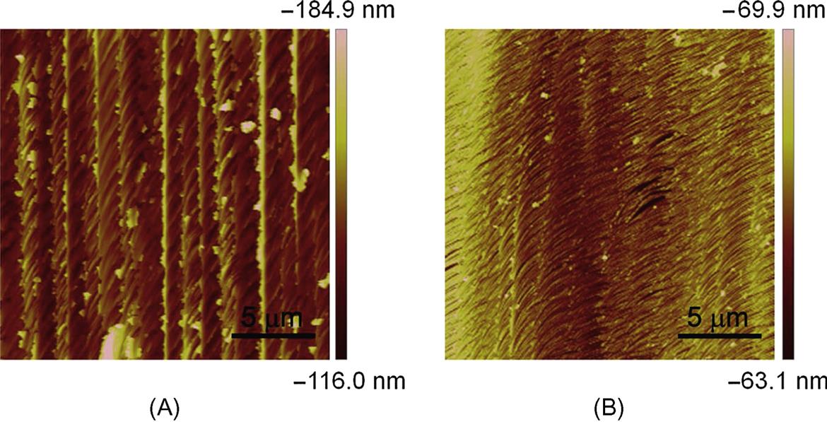
Moreover, the surface quality achieved by the conical tip is worse than that obtained by the pyramidal tip for both feed modes as shown in Fig. 3.20. Fig. 3.21 shows the AFM images of the local area machined in the side and reciprocal feed modes, using the pyramidal diamond tip. For the side feed mode presented in Fig. 3.21A, the formed burrs are increased and remained in the machined surface. For the reciprocal feed mode, the machined surface is polished by the tip for the second time when the tip retraces from the point 1 to the point 2, as presented in Fig. 3.19A. Therefore, the surface is much smoother under this condition. The corresponding Ra values become smaller, as shown in Fig. 3.20.
3.6.3 Fabrication of typical microstructures
Machining microchannels with the width less than 100 μm using this technique is an important advantage compared to the conventional micromilling process. These types of microchannels will be employed in the microfluidic application. Therefore, in this section, some complex 2D microstructures like microchannels are machined by this method. The conical diamond tip is used for the uniform width of the channels and is unaffected by the different feeding directions. The revolving frequency is 10 Hz. The diameter of the tip’s trajectory is 5 μm. The feed rate per revolution is 1.0 μm. The samples are the injected mold polymer PMMA plate.
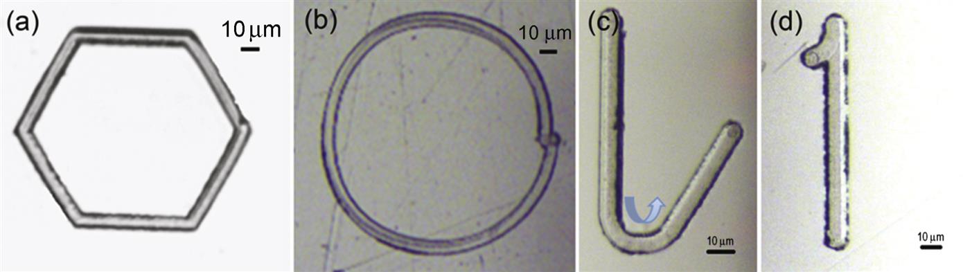
Figs. 3.22A and B show the hexagon and circular microchannels, respectively. The length of the hexagon microchannel is 50 μm. This channel is closed very well, indicating that the position accuracy of the X-Y precision stage is enough for this process. The diameter of the circular microchannel is 100 μm. The start point does not coincide with the end point under this condition. The accumulated error of the precision stage will play a role in the machined results, which can be reduced by a compensation process. By using the AFM to measure the machined surface, the surface roughness (Ra) 30–50 nm is obtained. In the microfluidic field, a straight channel connects to the circular channel. As shown in Fig. 3.22C, two straight microchannels, with the angle of 30°, connect to a circular microchannel, with the central angle of 150°. The lengths of two straight channels are 200 and 120 μm, and the radius of the circular microchannel is 40 μm. Using the same machining process, a microstructure letter “1” consisting of a circular microchannel with the central angle of 30° and a straight microchannel with the length of 120 μm is presented in Fig. 3.22D.
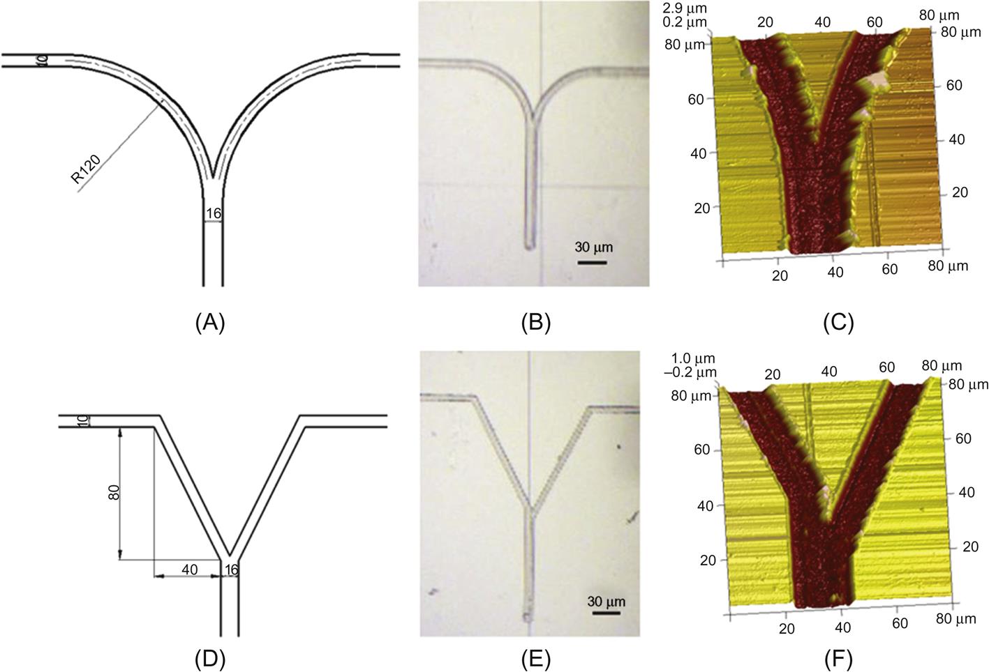
To confirm this approach further, using the same machining parameters, two kinds of Y-type microchannels, which are often used in the microfluidic fields, are machined. Figs. 3.23A and D show the dimensions of the microchannels. The unit used in the figure is the micron. Figs. 3.23B and D give the optical images of the machined channels. The Figs. 3.23C and F are the AFM images of the intersection area. The surface roughness (Ra) of the area at the bottom of the microchannel can reach up to 37.8 nm.
Moreover, the microstructure array can also be machined by this method. Fig. 3.24 shows a local area of the array with the square length of 10 μm and the distance between adjacent channels of 10 μm. The number of the channel is 10 for orthogonal directions. Owing to the employment of the conical diamond tip, as shown in Fig. 3.24B, some materials are not effectively removed and are piled up on the sides of the squares. The pyramidal diamond tip may result in a better result with optimized machining parameters. But the machining process is more complex.

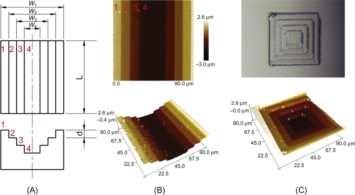
Using the schematic of Fig. 3.19, the layer by layer technique can be used to machine 3D microstructures by changing the dimensions of the micropits. Each pit is machined row by row, and each row is based on the machining method of the channel. As shown in Fig. 3.25A, the surface 1 is first milled with the dimension of width W1 and length L. After finishing surface 1, the tip engages downward to the prescribed depth (D) and then begins to machine surface 2 with the dimension of W2 and L using the same center line as the surface 1. And so on, for the surfaces 3 and 4. To obtain the structure with the smooth edges and a better surface bottom quality, the optimal machining method for the channel (as above studied in Fig. 3.14) has been adopted for machining aluminum alloy. Fig. 3.25B shows that the ladder structure is successfully machined. It can be seen that the structure has smooth steps with different depths. The distance between two layers is set to 1 μm. Owing to the high stiffness of the actuator, the machined depth can be well controlled. In addition, due to the difference of the material properties, under the condition of machining PMMA, the best way (Fig. 3.12D) of machining aluminum alloy does no longer work, while the machining way in Fig. 3.12A is the best case for PMMA which can produce the channel with two smooth sides. Therefore, based on the machining process of the channel, the 3D structures are machined on the PMMA surface as shown in Fig. 3.25C. The optical image in Fig. 3.25C shows the structure is made up of square pits with different dimensions. From the above analysis, while machining the pit on the aluminum alloy surface, the burr will occur at the top side (Fig. 3.14D) and other three sides are smooth. However, it can be found that comparing with the pit machined on the aluminum alloy surface, the pit on the PMMA surface in Fig. 3.25C has four smooth sides, which is mainly due to the brittleness property of PMMA material.
3.7 Summary and future works
The micromachining technique is based on the tip orbital motion, which is a new technology derived from the micromilling process and the AFM-tip based nanoscratching technique. By the trajectory movement of the diamond tip combined with the feed movement of the precision stage, it is able to machine microstructures like the microchannel, the microstep structure, and so forth on wide-range material surfaces. In this chapter, the principle of this micromachining technique is presented, and then it is compared with the conventional micromilling process. Based on this idea, a micromachining setup is established using a nanopiezo stage to perform the orbital motion. Based on analysis of the machining mechanism, the processing experiments on different materials, including polymers and metals with the conical and pyramidal diamond tips, are carried out. The burrs formation and control approaches are studied. 2D and 3D microstructures are successfully machined, which indicates that this technique will be used in the microfluidic fields in the near future.
However, this technique is still a new mechanical machining method to machine microstructures. There are many important points that are needed to be clarified and studied in the future.
1. Improve the machining accuracy. Based on the studies in this chapter, results show that a high machining accuracy is obtained with a pyramidal diamond tip rather than the conical tip, which is also used by (Heamawatanachai & Bamberg, 2009, 2010). In order to improve the machining accuracy further, the pyramidal tip or an even more complex tip shape should be used and be designed specifically. This work must be supported by many experiments in the future. Moreover, using this kind of diamond tip, the machining scale is still at the micrometer range. If one wants to reach to the nanometer range, an AFM tip with the tip radius of less than 10 nm may be used as the cutting tool. Also, the orbital motion is still employed. Similar studies have been performed by Gozen et al. in 2010 (Gozen & Ozdoganlar, 2012a, 2012b). This machining process is defined as nanomilling, a rotating tip based nanomechanical manufacturing process. Actually, the technique presented in this chapter and Heamawatanachai’s studies (2009; 2010) can be defined as a novel micromilling process.
2. Improve the machining efficiency. Because no high rotation spindle is used in this work, a relative low machining efficiency becomes an obstacle in order to apply this technique to the industrial applications. Using a piezo tube can make the tip revolve more quickly (Heamawatanachai & Bamberg, 2009). However, a small moving range and a compensation process for the Z-axis also lead to a low machining efficiency for the large scale microstructures. In our works, a nanopizeo stage is used, and a large machining scale can be easily obtained. However, the tip cannot move as fast, which results in a low machining efficiency. Therefore, in future studies of this technique, a large moving range and a relative high moving frequency are both required for the moving parts. Some new techniques in the motion parts will push this technique ahead.
3. Expand the workpiece materials. In this chapter, only the Al alloy and the polymer PMMA are used. In the previous studies, brittle and ductile materials including silicon, Ti, and Al alloy are machined with the conical diamond tip (Heamawatanachai & Bamberg, 2009). By using the pyramidal diamond tip and different kinds of trajectories, a better surface quality may be achieved. Therefore, in future studies, more types of materials should be explored further, based on these results. Moreover, previous studies also found that there is a severe tip wear when machining Ti, and different kinds of burrs and cracks exist when machining some materials. The ultrasonic vibration assisted method may make the machining quality better on more sample material surfaces.
4. Machine more complex microstructures. To date, only 2D microchannels structures and simple 3D microstructures have already been demonstrated by this technique. As a machining method similar to the micromilling process, complex microstructures can be machined by this method. This must depend on the insight into the machining mechanism of this technique and the detailed studies of the optimization of the processing parameters.
5. Applications of the machined microstructures. Previous works have confirmed that this technique is a low cost, highly accurate, and efficient mechanical machining method to machine microstructures less than 100 μm. The next important study of this technique is to use these microstructures in real applications. Currently, our group is doing this kind of work by applying the machined microchannel as the key part of the microfluidic chip. Moreover, many complex microstructures can be machined by this way. How to use them to demonstrate their effects on the properties such as the hydrophobic property and the optical characteristic, will greatly expand the application range of this technique.
Acknowledgments
The authors gratefully acknowledge the financial support from the Foundations for National Natural Science Foundation of China (51521003, 51222504), Self-Planned Task (SKLRS201606B) of State Key Laboratory of Robotics and System (HIT), the Program for New Century Excellent Talents in University (NCET-11-0812), the Fundamental Research Funds for the Central Universities (HIT.BRETIV.2013.08), and the National Program for Support of Top-notch Young Professors. The authors also gratefully acknowledge the works of Master Qiong Cai and Bachelor Dongze Wu.