
Using fiber-reinforced polymer (FRP) composites in bridge construction and monitoring their performance: an overview
B. Wan, Marquette University, USA
Abstract:
The superstructure and substructure of bridges can be made from all fiber-reinforced polymer (FRP), or from FRP composited with concrete or steel. The different applications of FRP composite materials in bridges are discussed. Common nondestructive evaluation/testing (NDE/NDT) methods are reviewed for their potential application in monitoring FRP bridges. Smart FRP bars and cables can be used to monitor the bridge, as well as help the bridge resist loads. A case study of monitoring a bridge with an FRP stay-in-place formwork deck is presented. A short commentary on likely future trends in FRP bridges and monitoring techniques is provided. Sources of further information related to FRP bridges and monitoring are listed at the end of this chapter.
Key words
fiber-reinforced polymer (FRP) bridge; FRP repaired and strengthened bridge; nondestructive evaluation/testing (NDE/NDT); smart FRP bridge; monitoring FRP bridge
1.1 Introduction
Because of their high strength and low density, fiber-reinforced polymer (FRP) composite materials have been widely used in the aerospace and automotive industries since the middle of the last century. FRP composites do not corrode in concrete in the way steel does. Goldsworthy (1954) predicted that FRP composites could be used as reinforcements in concrete and as structural members subject to corrosive environments. Glass fiber reinforced polymer (GFRP) rods were used first as reinforcements for concrete buildings. Since the late 1980s, FRP rebars have been used more extensively in concrete structures, especially in highway bridge decks, because of their resistance to corrosion (Bank, 2006). For the same reason, FRP composites have been used more and more widely when repairing and retrofitting deteriorated bridge superstructures, to reinforce bridge decks, girders and piles, and when replacing structural members (e.g. decks). FRP materials are also increasingly being used in bridges because new manufacturing techniques have reduced their cost (Telang et al., 2006). Although FRP materials have been used in the manufacture of missiles, planes, cars, boats, tanks, sporting goods, etc. for over half a century, their use in building bridges is still relatively recent. How well FRP composites in bridges will perform in the long term is one of our major concerns. Therefore, a monitoring program is normally set up to examine the behavior of FRP composites in demonstration bridges constructed around the world.
In this chapter, we consider how the superstructure and substructure of bridges can be made up of all FRP, or of FRP composited with concrete or steel. We discuss the different applications of FRP composites in bridge construction. Then we look at how bridges constructed using FRP composites are monitored by visual inspection and experimental nondestructive evaluation (NDE) techniques. Such evaluation can reveal damage such as blistering, voids, discoloration, fiber exposure, cracks, and scratches. We review common NDE techniques to see if they are suitable for monitoring FRP bridges, and we present a case study of a bridge with an FRP stay-in-place (SIP) formwork deck. This chapter also comments briefly on likely future trends, and includes sources of further information and advice.
1.2 Fiber-reinforced polymer (FRP) composites for bridge construction
FRP composite materials have been widely used to repair deteriorated bridges and to retrofit bridges that do not meet updated code requirements, and especially to retrofit columns to improve their seismic load capacity. They are also used in new construction as reinforcement in concrete decks, SIP formworks, pure FRP bridge decks, composite columns/piers, cables for suspension bridges, pedestrian bridges, and more. In fact, FRP composite materials can be used to replace steel in almost any component in bridge construction.
1.2.1 FRP pedestrian bridges
Because of their light weight and corrosion resistance properties, FRP profiles have been increasingly used in the decks and superstructure members of bridges since the mid 1970s (Bank, 2006). FRP was first used in short-span pedestrian bridges, the first FRP pedestrian bridge being built by the Israelis in 1975 (Tang and Podolny, 1998). Since then, hundreds of FRP footbridges have been built worldwide. The main structural type of these bridges is the truss. Cable-stayed and other traditional styles are also used (Feng, 2012).
Because of the low modulus of FRP composite materials, the stiffness of a pure FRP deck is relatively low, and thus deflection control is an issue. Relatively small amounts of concrete can be used to increase the stiffness of an FRP footbridge deck, keeping the total weight low. Bank et al. (2010) used pultruded GFRP planks with a cement board or concrete topping slabs to form a 75 mm deep hollow section to be used in place of traditional timber decking in pedestrian bridges. Neto and La Rovere (2010) developed a footbridge deck system consisting of a fiber reinforced concrete (FRC) top layer supported by GFRP wide-flange pultruded profiles, with foam blocks filling the voids to keep the bottom flat.
Researchers also tried combining FRP materials with other newly developed construction materials to improve the performance of pedestrian bridges. Mendes et al. (2011) designed and analyzed a 12 m long single span pedestrian bridge with two GFRP I-shape profiles and a thin steel fiber reinforced self-compacting concrete (SFRSCC) deck. Both steel anchors and epoxy resin were used to ensure the composite action between the two materials. The SFRSCC deck increases the flexural stiffness of the whole structure, resists compression stress, and provides better crack control. The GFRP I-shape resists tensile stress in this bridge.
The structural style can also be modified to counteract the disadvantage of the low modulus of FRP composite materials. Caron et al. (2009) proposed a self-stressed footbridge in which energy stored elastically in the bent bow generates the required stress to maintain the stability of the whole structure. This self-stressed FRP footbridge takes advantage of the low stiffness of the pultruded FRP profile.
1.2.2 FRP vehicular bridges
Using knowledge and experience gained from building FRP pedestrian bridges, engineers went on to build all FRP vehicular bridges. The first FRP vehicular bridge was built in Beijing, China in 1982. It has six hand-laminated GFRP sandwich girders, spans 20.7 m, and is 9.2 m wide (Ye et al., 2003). In the early 1990s, many FRP deck systems were developed and evaluated in laboratories and in demonstration projects supported by federal or local departments of transportation and FRP manufacturers. Many of these FRP bridges were built with short spans over secondary or rural roads where traffic is light. The first US all-composite vehicular bridge went into public service on 4 December 1996 in Russell, Kansas (Tang and Podolny, 1998). In 1998, the US Federal Highway Administration (FHWA) set up the Innovative Bridge Research and Construction (IBRC) Program to develop cost-effective innovative material applications in highway bridges (FHWA, 2003). This program boosted the use of FRP materials in highway bridges in the US. Many FRP vehicular bridges have also been constructed in Europe, China, and Japan over the past two decades.
Replacing deteriorated reinforced concrete decks with FRP decks is an attractive option for increasing the live load capacity of old bridges because FRP decks are much lighter than concrete decks. For example, the non-composite concrete deck of the Bentley Creek Bridge in New York was replaced with an FRP deck in 1999. Changing the weight and stiffness changes the natural frequencies of such a bridge (Hag-Elsafi et al., 2012). FRP decks are also composited with steel or concrete girders and trusses in new bridges (Turner et al., 2003; Liu et al., 2008).
FRP deck configurations can be cellular, honeycomb, or hybrid/sandwich. Cellular decks are manufactured by combining several pultruded FRP profiles to create different geometries. Although the weight of cellular decks is very low compared to other deck formats, their stiffness is relatively low and may cause buckling. An FRP honeycomb panel consists of top and bottom face sheets and a sinusoidal core (Davalos et al., 2012), whereas the compression zone of an FRP-concrete hybrid deck often uses concrete (Aref et al., 2005; Schaumann et al., 2009). A sandwich panel consists of upper and lower layers and a core, with the bottom layer usually made of FRP, and the top layer and the core made of FRP and/or traditional materials. Many creative FRP sandwich decks have been invented. For instance, Schaumann et al. (2008) produced a sandwich deck panel consisting of three layers: an FRP sheet with T-upstands for the bottom skin, lightweight concrete for the core, and a thin layer of ultra-high-performance reinforced concrete for the top layer. Ji et al. (2009) proposed a composite sandwich panel consisting of a wrapped hybrid core of GFRP grid and multiple steel box cells with upper and lower GFRP layers.
1.2.3 FRP reinforced concrete bridge decks
FRP composite materials were first used to reinforce concrete structures in the 1950s (Rubinsky and Rubinsky, 1954). Corrosion of steel reinforcement is a major problem for bridge decks, worsened by increased traffic and deicing salts. As FRP composite materials are corrosion resistant, they are a good alternative to steel reinforcement for concrete bridge construction. Because of cost, GFRP reinforcement is more attractive than carbon FRP (CFRP) or aramid FRP (AFRP) for bridge decks, and has been used in many bridge decks in North America (El-salakawy et al., 2005; Bank, 2006).
One of the barriers to using FRP in bridge decks is the initial material cost. Bouguerra et al. (2011) tested different parameters of eight full-scale concrete decks including slab thickness, concrete compressive strength, reinforcement ratio, and reinforcement type, and found that all slabs failed in punching shear. Punching shear was still the critical failure mode for concrete slabs reinforced with FRP grids when the span increased (Brunton et al., 2012). The common slab-on-girder superstructure used for highway bridges may also cause punching shear failure in a bridge deck due to the lateral restraint of the supporting girders and the continuity of the slab (El-Ragaby et al., 2007). Such lateral restraint, however, can produce compressive membrane action in the FRP reinforced concrete slab, which benefits the load-bearing capacities and deflection control of the bridge. Zheng et al. (2012) found that the reinforcement percentages did not affect the ultimate capacity of the GFRP-reinforced concrete bridge deck with the compressive membrane action. Therefore, the current high reinforcement requirement based on flexural design is very conservative.
The punching shear failure mode may lead to a reduction in FRP reinforcement required in bridge decks and thereby reduces the initial cost of GFRP-reinforced concrete bridge decks (Bouguerra et al., 2011). Berg et al. (2006) compared the cost of a two-span highway bridge deck with an FRP-SIP formwork, deformed FRP bars, and a prefabricated pultruded FRP reinforcing grid, and concluded that an FRP reinforced bridge deck might be cost-effective even though its material costs were 60% higher than those of a steel-reinforced bridge deck. The saving of labor costs and construction, and maintenance due to potential long-term durability, can therefore overcome the initial high material cost.
Fatigue life and durability are also major concerns when using GFRP reinforcement in bridge decks. El-Ragaby et al. (2007) found that the bridge decks with GFRP reinforcement had a better fatigue performance and longer fatigue life than traditional steel-reinforced concrete decks. But laboratory tests showed that when GFRP is exposed to an alkaline solution, which simulates the concrete pore water solution, its mechanical properties (i.e., elastic modulus, tensile, shear, and bond strengths) decrease significantly (Bank and Russell, 1995; Sen et al., 2002). So, although several bridges had used GFRP as reinforcement at the end of the 1990s, the designers of these bridges were questioning the durability of the GFRP bars (Bradberry, 2001). However, ISIS Canada studied several in-service bridges with GFRP-reinforced concrete decks and found no degradation of the GFRP in the concrete of structures exposed to natural environmental conditions for durations of 5–8 years (Mufti et al., 2005). Therefore, the deterioration of a GFRP-reinforced concrete deck in field is not as serious as results from laboratory tests had indicated.
1.2.4 FRP stay-in-place formworks for bridge construction
FRP-SIP formworks serve as formworks for fresh concrete during construction and as reinforcement during service. They can be used as open forms for bridge decks, and as closed forms for bridge columns. The major advantages of FRP-SIP formworks are that they are lightweight, do not have to be removed after concrete is set, and provide crack control (Bank et al., 2007; Oliva et al., 2008; Hanus et al., 2009). However, moisture may be trapped on the interface between the FRP formwork and the concrete, so increasing freeze-thaw damage (Wan et al., 2007; Hanus et al., 2009).
FRP-SIP formworks can be used to build reinforcement-free concrete decks if the gaps between the flange edges of the precast concrete girders are small (Bank et al., 2007). Although no reinforcement is provided, such a slab is normally made by FRC for crack control. Bank et al. (2009) proposed a design specification for FRP-SIP formworks for concrete bridge deck construction. It includes a permanent FRP-SIP formwork system, a two-way mat of FRP I-shaped pultruded bars, and three-piece orthogonally placed cross-rods.
Since the FRP-SIP formwork serves as reinforcement during service, the bond between the FRP-SIP form and the concrete is very important for developing composite action, and it is made up of both mechanical and chemical bonding. Aggregates can be bonded with epoxy to the FRP plank before the concrete is poured to improve the mechanical bond (Bank et al., 2007). Sand coating improves the connection between the FRP form and the concrete, and increases the flexural capacity of the composite deck (Cho et al., 2010; He et al., 2012). Using penetrating bars inserted into the webs of the FRP-SIP formwork and perpendicular to the major fiber direction of FRP formwork can also improve mechanical bonding (He et al., 2012). Wet bonding, where the FRP form is coated with a layer of adhesive resin and fresh concrete is poured before the resin is cured, can be used to improve chemical bonding between the FRP-SIP formwork and the concrete (Li et al., 2010).
Concrete-filled FRP tubes have been studied and used as bridge piers and girders (Son and Fam, 2008). During construction, FRP tubes act as a permanent formwork and, when in service, they can protect the concrete from aggressive environments, provide confinement, and act as shear and/or flexural reinforcement (Mohamed and Radhouane, 2010). Because of the confinement effect, using an FRP-SIP formwork for a bridge column can improve its deformation capacity significantly (Ozbakkaloglu and Saatcioglu, 2006, 2007), thereby improving its seismic performance. FRP-SIP formworks can also be used for bridge girders to create a hybrid FRP/reinforced concrete bridge superstructure (Chen et al., 2009).
1.2.5 FRP cable-stayed bridges
A cable-stayed bridge is one where the bridge deck is stayed by cables attached to towers. It is a very efficient means of achieving a long span and aesthetically pleasing. The span of steel cable-stayed bridges has now exceeded 1000 m, with the Sutong Bridge spanning the Yangtze River in China with a main span of 1088 m, being the longest cable-stayed bridge in the world until 2012. Currently, the longest cable-stayed bridge in the world is Russky Bridge in Russia, which has a main span of 1104 m and was completed in July 2012. With a longer span, the self-weight of traditional steel and concrete limits the advantage of a cable-stayed structure, and steel cables also develop sag effect and corrosion problems.
As a high strength and lightweight material, FRP has the potential to span further. Moreover, it does not corrode and, therefore, it is logical to use FRP in a cable-stayed bridge to achieve a super long span. Meier (1987) proposed building a CFRP cable-stayed all FRP bridge to cross the Strait of Gibraltar with a maximum span of 8400 m. The first FRP cable-stayed bridge to be constructed, however, was Links Leader Bridge in Scotland, which was constructed in 1992 with a main span of 63 m (Khalifa et al., 1996). After that, several such bridges for pedestrians and vehicles were constructed in other countries, including Herning Bridge (Denmark, 1999), I-5/Gilman Bridge (USA, 2002) (Scalea, 2000), and a pedestrian bridge at Jiangsu University (China, 2004) (Wu and Wang, 2008). Wang and Wu (2010) evaluated the suitability of different FRP and hybrid FRP cables for 1000–10 000 m super-long-span cable-stayed bridges. They concluded that basalt FRP (BFRP), hybrid basalt and steel wire FRP (B/SFRP) 20% and 30% cables have pronounced integrated advantages compared with steel cables within a span range of 3000 m, and that hybrid B/CFRP 25% and 50% cables exhibit cost advantages over CFRP cables, with promising applications for longer spans (Wang and Wu, 2010).
1.2.6 Retrofitting existing bridges
Existing bridges may have deteriorated due to:
• environmental factors, as with the corrosion of steel rebars in bridge superstructures
• design and construction errors resulting in lower load capacity than planned.
Deteriorated bridges have to be repaired and, due to the updating of design codes, some may no longer satisfy current requirements (especially seismic resistance) and must also be strengthened. FRP materials have exceptional stiffness- and strength-to-weight ratios, and do not require heavy equipment to be installed. Because of this, external bonding of FRP plates or sheets has become a popular method for strengthening or retrofitting reinforced concrete bridges and other structures (Bakis et al., 2002; Teng et al., 2002). The epoxy normally used in FRP strengthening can be cured and acts quickly. As it reduces the time that traffic is blocked or detoured, FRP strengthening is a very attractive solution.
For flexural strengthening, there are three major methods of bonding FRP composite materials to the soffit of the bridge girders and the bottom of the decks:
1. Using an adhesive to bond premanufactured FRP strips to the surface of bridge members.
2. Hand lay-up, in which dry fiber fabrics or sheets are saturated with liquid adhesives in field and bonded to the bridge members. A number of layers of FRPs may be used in hand lay-up applications.
3. Near surface mounting (NSM), where grooves are cut along the surface of the concrete members. Premanufactured FRP strips or small-diameter FRP bars are inserted into the grooves and bonded adhesively.
FRPs can also be wrapped around concrete columns or piers to increase their capacity and ductility. After the Prieta earthquake in 1989, FRP and steel jackets became popular and routine methods of retrofitting concrete bridge piers/columns in the US (Tang and Podolny, 1998; Bank, 2006). Compared with steel jackets, FRP composite materials are lightweight and corrosion free, making them more attractive in most cases. As well as increasing the ductility of bridge columns (Moran and Pantelides, 2002) and repairing piers or piles damaged by steel reinforcement corrosion (Pantazopoulou et al., 2001; Winters et al., 2008), FRP wrap is used as a barrier to prevent chloride penetration further corroding steel reinforcement (Klaiber et al., 2004).
1.3 Monitoring problems in bridges using FRP composites
Although FRP composite materials have a lot of advantages, as mentioned in the previous sections, they also have some disadvantages compared with steel and concrete used in bridge construction:
• Besides its high initial cost, pultruded FRP has lower stiffness and, therefore, deflection control is necessary in FRP bridges.
• Most FRP deck systems are enclosed, making it difficult to detect problems by visual inspection.
• Compared with traditional materials used in bridge construction, there are relatively few long-term performance data on FRPs, and not enough for bridge owners and engineers to use FRPs as confidently as they use steel and concrete. Therefore, a monitoring program is normally required after the construction of FRP bridges (Turner et al., 2003; Foley et al., 2010).
1.3.1 Potential problems of FRP bridges in service
In this section, we consider potential problems detected in FRP bridges in service.
An FRP composite material used in a bridge in field may deteriorate or become damaged due to moisture absorption, alkali solution in concrete, temperature cycling, freeze–thaw, creep and relaxation, fatigue, UV radiation, or fire (Karbhari et al., 2003). The following damage may be observed:
After moisture penetrates FRP components, local hydrostatic pressure between the layers and stresses due to freeze–thaw cycles may delaminate the layers and cause bubbles on the surface i.e., blistering.
Voids are submerged gaps within the laminates of a deck, and are usually invisible.
A long period of exposure to UV lights, heat, and the chemical environment may cause FRP discoloration.
Excessive stretching or shearing of the fabric during wet-out may cause wrinkling.
Improper handling may cause fiber exposure and scratches on the surface of FRP components. If it is not repaired, the damage would make the fibers susceptible to moisture and contamination, leading to further laminate deterioration in the area.
Vehicle and debris impact can cause cracks and result in the material separating through the entire thickness of the laminate (Telang, 2006).
Moisture trapped between the FRP-SIP formwork and the concrete, and its corresponding freeze–thaw cycles, may cause the loss of shear strength between the FRP formwork and the concrete, and delamination (Wan et al., 2007; Foley et al., 2010). FRP repaired and retrofitted concrete bridge flexural members also suffer delamination problems (Wan et al., 2006).
FRP decks can be connected to steel girders by shear studs, clips, or bolts. For shear stud connections, the studs are installed onto the steel girders through stud pocket openings, and then the stud pockets are grouted to obtain composite action between the FRP and the steel girder (Turner et al., 2003). For clip connections, the FRP deck is vertically clamped to the girder flange with steel side clips, and for bolt connections, threaded studs, nuts, and washers anchor the FRP deck to steel girder (Telang, 2006). If the girder is a precast concrete girder, a set of bent bars is cast as shear studs, and then inserted into the stud pocket openings in the FRP deck to be grouted. Good deck-to-girder connections are critical to the composite action between the deck and girder, and the integrity of the entire structure in service. Damage to these connections will cause gaps or relative movement between the deck and girder, and the bridge will no longer be safe for pedestrians and vehicles. However, these connections, apart from the bolted connection, are hidden in grout and are difficult to inspect.
It is possible to connect FRP deck-to-deck using interference fit with shear keys, tongue-and-groove connections, or butt joints with shear-splice plate strips (Telang, 2006). These connections are relatively easy to inspect, but problems can also develop in these areas as a result of improper installation, large vehicle loads, and environmental exposures. Loosened deck-to-deck joints may cause the decks to move vertically relative to each other, causing an uneven surface on the bridge, and cracks in the overlay and surface.
1.4 Common nondestructive evaluation/testing (NDE/NDT) methods for bridges using FRP composites
FRP bridges can be inspected and monitored by common NDE/NDT methods that have been used widely by bridge maintenance engineers and by engineers in the aerospace and ship industries that have a longer history of using FRP composite materials. Some simple but efficient methods, such as visual inspection, chain dragging, and tap testing, do not need special equipment. Some methods, such as thermal, acoustic, and ultrasonic testing, radiography, modal analysis, and in situ load testing, are more complex and do require specific equipment (Telang, 2006).
Visual inspection is the simplest method and is widely used to check FRP bridges. The inspector uses the naked eye with the help of simple tools, such as a flash light, measuring tape, or mirrors, to rapidly detect defects and problems on the bridge. Cracks, delamination, discoloring, voids, and deformations detected by visual inspection may be further investigated by more sophisticated methods if needed. The major disadvantage of visual inspection is that it can only detect surface problems and cannot quantify the extent of the damage.
In tap testing, the inspector taps the FRP surface with a coin, hammer, or electronic tapping unit and detects delamination or voids by listening to the distinctive changes in sound. Although it does not require expensive equipment or extensive training, tap testing can efficiently identify most common problems in FRP bridges in conjunction with visual inspection. Void in the bottom of an FRP deck was found in an FRP slab bridge by tapping the underside of the bridge surface with a rubber mallet (Alampalli, 2006). Visual inspection and chain dragging were also performed on this bridge to check for delamination between the polymer-concrete wearing surface and the FRP structure (Alampalli, 2006). Similarly to tap testing, in chain dragging a steel chain is dragged along the bridge deck and an inspector listens to the changes in acoustic response to locate potential delamination (Guthrie et al., 2006). Rosenboom et al. (2009) found that visual inspection and tapping (by a steel rod) were very effective in inspecting bonding between FRP and concrete for FRP-strengthened prestressed concrete girders.
The theory behind infrared thermography (IRT) is that subsurface defects affect heat flow in a material (Rens et al., 2005). An ambient or artificial heat source is used to heat one side of the bridge deck, and an infrared camera is used to measure the temperature variation of the other side, to detect discontinuities inside the tested area, such as delamination, debonding, impact damage, moisture, and voids. IRT imaging has been successfully used to evaluate the quality of the bond between FRP and concrete in an FRP-strengthened reinforced concrete bridge (Hag-Elsafi et al., 2004; Taillade et al., 2012). Digital IRT was used to detect subsurface defects in FRP bridge decks and the debonding between the wearing surface and underlying deck (Halabe et al., 2007). The temperature inside a bridge can also be measured by thermal sensors. Teng et al. (2003) installed thermal sensors on GFRP-wrapped concrete columns of a highway bridge to monitor the temperature difference between the FRP and substrate concrete column over 2 years and detect possible debonding.
The principle behind acoustic testing is that a structure under certain load levels produces acoustic sounds or emissions (AE) due to deformation, cracks initiating and growing, cracks opening and closing, fibers breaking, and delamination in composite materials (Telang, 2006). Testing is carried out with AE piezoelectric sensors, couplant, multi-channel data acquisition hardware, and a fully integrated analysis and data acquisition software system. Gostautas et al. (2005) successfully used AE to evaluate six full-scale GFRP bridge deck panels with different cross-sections.
In ultrasonic testing, high-frequency sound waves are sent into the material being tested, and the change of speed of the reflected waves is detected. Pulse velocities can be correlated to material quality or bond quality to detect discontinuity (Hellier, 2001). An ultrasonic testing system includes a transducer, pulser, receiver/amplifier, and a display screen. Ultrasonic testing has been successfully used to detect debonding damage in FRP-strengthened concrete members (Bastianini et al., 2001) and an FRP-strengthened cast iron bridge (Bastianini et al., 2004). Mahmouda et al. (2010) used surface acoustic waves (SAWs) to evaluate the interface deterioration of CFRP-strengthened concrete specimens, and proposed using this method to monitor the health of concrete bridge structures repaired or retrofitted with FRP composite materials. The operator of ultrasonic testing should have a high level of expertise to properly conduct the test and interpret the data, and be certified by the American Society of Nondestructive Testing (ASNT) (Telang, 2006).
Radiography uses X-rays or gamma rays to penetrate the deck and ‘see’ defects. Defects in an FRP deck, such as delamination, differ from healthy parts in the amount of penetrating radiation they absorb. The radiographic film or computer screen of the test system can clearly indicate where there are defects.
If an FRP bridge has deteriorated, its overall stiffness will change, and therefore its dynamic response will differ from that of the original structure. Using this theory to evaluate the condition of a bridge structure is known as modal analysis. To perform a modal analysis, the bridge is instrumented with an array of accelerometers, and then prescribed dynamic load tests are performed to extract modal parameters with selected frequencies and mode shapes (Telang, 2006). How much the modal parameters differ from the baseline parameters indicates how much the FRP bridge has deteriorated or been damaged since its original construction. Modal analysis was used to characterize the dynamic behavior of the first FRP composite bridge superstructure built in New York State (Alampalli, 2006). Guan et al. (2007) installed a distributed array of accelerometers on an FRP highway bridge to collect structural vibration data and carried out a modal analysis to determine the long-term performance of the bridge.
For in situ load testing, a known live load with predefined patterns is applied to a bridge instrumented with strain gages, accelerometers, and displacement sensors. The strain and deflection of the bridge are recorded and analyzed to evaluate its performance. The load test can be performed over a certain time interval (e.g., 1 or 2 years) to discover any change in bridge response and determine any deterioration or damage during this time. Repeated in situ load tests can help to monitor the long-term performance of a bridge.
Because most of the FRP bridges built over the past two decades were built for demonstration purposes and technical verification, they all had short- and/or long-term monitoring programs, including in situ load testing, set up for them (Shenton and Chajes, 1999; Alampalli and Kunin, 2001; Turn et al., 2003; Hag-Elsafi et al., 2004; Reising et al., 2004; Shahrooz and Boy, 2004; Zhou et al., 2005; Alampalli, 2006; Foley et al., 2010). The case study in Section 1.5 describes one such program, which monitors a highway bridge using an FRP-SIP formwork and an FRP grid in a concrete deck.
Radiography, modal analysis, and load testing require special and normally expensive equipment, compared to visual inspection, tap testing and chain dragging, thermography, and acoustic testing. They also require a relatively high level of expertise to operate and interpret the data, and are time consuming. Therefore, they are only used for detailed assessments of potentially damaged or defective areas already identified using simpler methods (e.g. by visual inspection, chain dragging, or tap testing). More detailed discussion of common NDE/NDT methods can be found in many books and manuals covering this topic for regular and FRP bridges (Hellier, 2001; Telang, 2006).
1.4.1 Smart FRP bridges
This section introduces the recently developed smart FRP bars and smart FRP cables that integrate FRPs and fiber optic sensors used to monitor FRP bridge components. The use of strain gages to measure the strains of bridge components is a well-developed technology widely used in FRP bridge monitoring projects (Shenton and Chajes, 1999; Alampalli and Kunin, 2001; Turn et al., 2003; Foley et al., 2010). However, strain gages can be damaged in field by environmental exposure or vandalized. Instead, optical fiber Bragg grating (OFBG) sensors can measure the strain and temperature of a component by monitoring the Bragg light spectrum of the grating reflection and transmission inside the optic fibers. OFBGs have a small diameter and are lightweight, and therefore have only a very small effect on the components tested when they are installed. OFBG sensors are not affected by electromagnetic interference and can be easily made into distributed sensor networks, and have a long service life. Therefore, they are attractive for long-term monitoring of bridges (Zou et al., 2003).
Two different fiber optic sensors were installed in an FRP reinforced concrete highway bridge in Canada to create a smart bridge that continuously sent bridge information to the engineers’ office (Shehata and Rizkalla, 1999). More recently, OFBG sensors were installed on Hong Kong’s Tsing Ma Bridge and successfully monitored the performance of the bridge in service (Chan et al., 2006). Jiang et al. (2010) also embedded global and local fiber optic sensors in FRP materials to create a smart FRP system to strengthen reinforced concrete and steel members.
As the bare OFBG sensor is fragile, it is easily damaged if directly installed on structural members. For this reason, some researchers integrated OFBG sensors into FRP bars or cables to create smart FRP bars or smart FRP cables (Kalamkarov et al., 1999, 2005; Zhang et al., 2006; Lu and Xia, 2007; Li et al., 2009, 2011, 2012). To produce OFBG FRP smart bars, a bare OFBG sensor is put in the center of the die for FRP bars or cables during pultrusion, which are then cut to the required length for structural applications (Zhou et al., 2003). The bond between the smart FRP bar and the concrete is critical in transferring the strain between them. In order to improve this bond, surface deformations are normally added to the FRP bars and sand used to roughen their surface (Zhou et al., 2003; Kalamkarov et al., 2005).
To make a smart cable for cable-stayed bridges, a steel strand was opened; then its middle wire was taken out and replaced by an FRP smart bar; finally, the rest of the wires and the FRP smart bar were re-twisted to make a new smart strand (Li et al., 2011). Smart bars and cables with OFBG can be used as regular bars and cables, but they also act as sensors measuring strain and temperature inside structural members. Wang et al. (2009) installed smart GFRP bars with fiber optic sensors in reinforced concrete beams strengthened by NSM FRP bars to achieve the dual purposes of structural strengthening and strain monitoring.
1.5 Case study: monitoring a bridge with an FRP composite stay-in-place (SIP) formwork and an FRP composite reinforced concrete deck
As part of the FHWA IBRC Program, the state of Wisconsin constructed a highway bridge with decks using an FRP-SIP formwork and FRP grillage reinforcement in 2003 (Foley et al., 2005, 2010). The bridge superstructure is composed of traditional precast concrete I-girders acting compositely with the bridge deck. The bridge is Bridge B-20-133 on US Highway 151 in Waupun, Wisconsin, and it is a typical precast, pretensioned two-span continuous superstructure system as shown in Fig. 1.1. A 5-year program was set up to monitor its long-term performance with two in situ load tests at 2-year intervals and field inspections.

Electrical resistance strain gages are often used to record the strains in different components of a bridge during in situ load testing (Turner et al., 2003). As mentioned above, they have some drawbacks when used for long-term monitoring, for example, being vulnerable to environmental degradation, damage, and vandalism. Therefore, portable and removable strain sensors were developed and used to measure normal strains in the bridge deck and girders of this monitoring project (Schneeman, 2006; Foley et al., 2010).
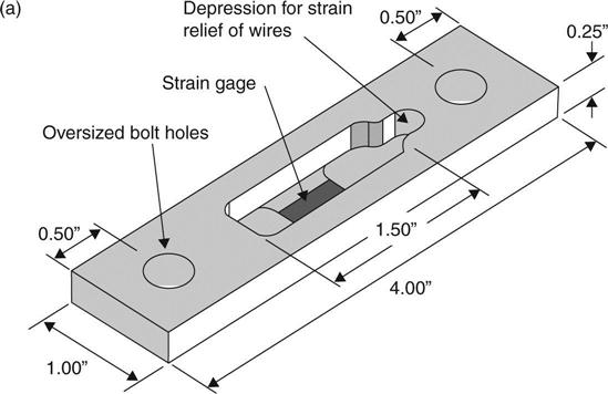
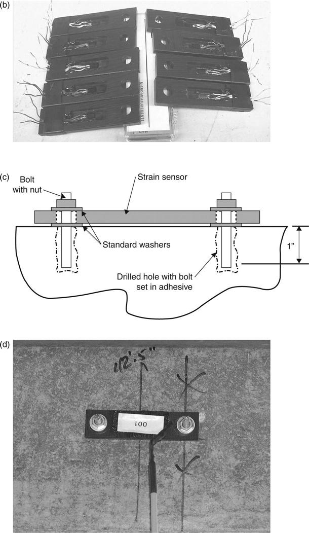
The portable strain sensor includes a material carrier with low modulus of elasticity for the strain gage and a conventional electronic resistance strain gage as shown in Fig. 1.2a and 1.2b. Two holes were drilled at each end of the portable strain sensor through which mechanical anchors were inserted to mount the sensor on the concrete girder or deck as shown in Figs 1.2c and 1.2d. For each sensor, a quick connect/disconnect tab was wired to the strain gage. The mechanical anchors and wires were installed permanently on the bridges. Before load testing, strain sensors were installed at designated locations on the anchors and connected to a data acquisition system via the quick connect/disconnect tabs. All strain sensors were tested and calibrated in the laboratory before they were used on the bridge. Details of the testing and calibration of the portable strain sensors can be found in Schneeman (2006).
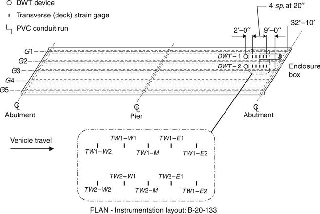
The removable strain sensors were used to measure the strains of the bridge deck and commercially available draw wire transducers (DWTs) were used to measure the deflection of the bridge deck relative to the bridge girders. A schematic illustrating the instrumentation is shown in Fig. 1.3. The instrumentation in this bridge structure was focused on measuring the distribution of wheel loads within the bridge deck and the deflection of the bridge deck relative to the girders.
Two load tests were conducted on this bridge in July 2007 and July 2009. A weighted dump truck was driven slowly onto the bridge and stopped at designated locations to test the deck strain and deflection. Two loading path protocols were used to generate large strains in the exterior and interior spans, and the data acquisition system recorded the strains and deflections when the truck was on the bridge. Details of the loading test process can be found in Foley et al. (2010) and Wan and Foley (2010). Peak deck deflections measured in the first and second load tests were similar, on the order of 0.381 mm. Therefore, it can be concluded that there has been no significant change in the flexure load transfer mechanism in the bridge deck over the 2-year period between the two load tests.
The strain measurements from the July 2007 load test were used to estimate the bridge deck width that resists wheel loading, and a standard specification design procedure for bridge deck analysis (AASHTO, 2002) was also used to calculate the live load bending moment when the bridge was subjected to the truck load. Compared with the results calculated from measured strains, the American Association of State Highway and Transportation Officials (AASHTO) specification (2002) methodology is conservative in estimating the bending moment per foot of width that would be seen in the deck. The moment strip width was also computed using the measured strain data (Foley et al., 2008) and compared with the results calculated using the AASHTO (2006) load and resistance factor design (LRFD) procedure. This shows that LRFD specifications are also conservative in analyzing this innovative FRP-SIP bridge deck.
Moisture accumulation at the interface between the FRP-SIP formwork and the concrete in this FRP-SIP bridge deck was assessed using a digital hygrometer inserted into holes drilled from the bottom of the deck to different depths. No moisture was found when the probe holes were drilled. Therefore, no moisture had accumulated when this test was conducted in 2009 when the bridge had been in service for 5 years. However, the humidity at the interface of the FRP-SIP formwork and the concrete was higher than at other locations, indicating a tendency for moisture to accumulate at the interface. Experimental work relating to this monitoring program has shown that freeze–thaw cycling and the presence of water could be detrimental to the interfacial shear strength between the FRP-SIP formwork and the concrete (Wan et al., 2007). Therefore, it is recommended that relative humidity is monitored at the interface for long-term evaluation of bridge decks with FRP-SIP formwork.
This bridge with its FRP-SIP deck and its sister bridge with a traditional steel-reinforced concrete deck were visually inspected in October 2005, July 2007, and July 2009. The visual inspections examined all superstructure elements including the abutments, piers, deck surface, deck soffit, and parapets. They revealed that both bridges were in very good condition.
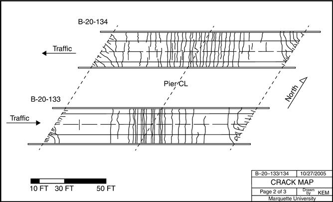
In the first visual inspection, scaled crack maps were drawn for both bridges as shown in Fig. 1.4. The figure shows extensive cracking in both bridge decks and that most of the cracks were concentrated in the negative moment regions above the central piers. A numerical simulation indicated that the traffic load combined with concrete shrinkage caused transverse cracking in the deck over the interior piers (Foley et al., 2010; Wan et al., 2010). The bridge with the FRP-SIP deck (Bridge B-20-133) appeared to have less cracking at the mid span location between the abutment and central pier than the bridge with the traditional steel-reinforced concrete deck (Bridge B-20-134). This may be a result of the SIP-FRP formwork restraining the shrinkage of the deck, as well as the tight spacing of the FRP grillage. The cracking at acute corners in skewed superstructures resulted from concrete shrinkage in the bridge deck. The visual inspection did not detect any cracking at the overhanging portion of the decks for either bridge. However, hairline cracks in the bridge decks had propagated to and through the parapet, with efflorescence showing on the underside of the overhang of each bridge deck. Because of the FRP-SIP formwork, it was impossible to check the condition of the concrete deck from the underside by visual inspection.
1.6 Future trends
The unique properties of high specific strength, high specific stiffness, and corrosive resistance have made FRP composite materials acceptable for all kinds of bridge construction, as described. Following two decades of field application and research, manufacturers, researchers, bridge engineers, owners, and government agencies are putting a lot of effort into increasing the application of FRP in bridges. To regulate design, construction, and inspection, different countries have published their own specifications and codes. As we gain greater understanding of their long-term performance, more bridges will be constructed using FRP composite materials. It is expected for more FRP to be used in the following three areas of bridge construction:
An FRP pedestrian bridge can be manufactured in a factory and then installed on site within several hours. Because it is light compared with a steel and concrete pedestrian bridge, the FRP pedestrian bridge does not require heavy equipment for transporting and installing. Its corrosion resistance also reduces its life cycle cost. Therefore, an FRP pedestrian bridge will be seen as a very attractive option when an old pedestrian bridge needs to be replaced or a new one needs to be built.
Contrary to results from accelerated tests in the laboratory, GFRP reinforcement did not show any deterioration in concrete decks after several years of service in field (Mufti et al., 2005). This has given bridge engineers and bridge owners the confidence to increase its application in areas where steel reinforcement corrosion is a serious problem, such as traditional steel-reinforced concrete bridge decks.
As the economy has developed, long-span bridges have been required worldwide to connect islands or cross straits. The high material strength of CFRP and the excellent structural style of a cable-stayed bridge enable an all FRP bridge to span much further than a bridge constructed using steel and concrete.
Basic and simple methods of bridge testing, such as visual inspection and tap testing, will be the regular NDE/NDT methods for FRP bridges. When needed, thermography, load testing, and other test methods, as discussed in the previous section, will be used. It is believed that more new FRP bridges will be constructed as ‘smart’ bridges, with various sensors integrated into the decks, girders, cables, and other important components to continuously monitor the performance of each bridge. The data of these smart bridges will be transmitted through wired or wireless networks to an office where they will be analyzed. Some prototype smart systems have already been established and installed on FRP bridges (Shehata and Rizkalla, 1999; Guan and Karbhari, 2006). In future, a complete system of software and hardware will be developed to automatically analyze technical data transmitted from the bridge. Once the critical parameter, such as the strain value at a predefined location, exceeds a certain threshold, the system will send an alert to the maintenance engineers to take action. Using such a system, engineers will be able to fix problems promptly when they first occur, avoiding further damage.
1.7 Sources of further information and advice
In recent years, a significant number of specifications and codes have been published to guide engineers when designing FRP bridges. In the USA, the American Concrete Institute (ACI) has published a series of guides on using FRP composite materials in concrete structures. All highway bridges in the US including FRP bridges should satisfy the requirements of the AASHTO Standard Specifications for Highway Bridges. AASHTO has also published Guide Specifications for Design of FRP Pedestrian Bridges. Canada, Japan, Europe, and China have published guide specifications for FRP applications in infrastructure.
The International Institute for FRP in Construction (IIFC) is the only international professional organization dedicated to the use of fiber reinforced composite materials in civil infrastructure (http://www.iifc-hq.org/). The IIFC hosts two official conferences in alternating years in which state-of-the-art research on FRP applications for infrastructures is presented and discussed. The FHWA maintains an FRP bridge library (http://www.fhwa.dot.gov/bridge/frp/frppaper.cfm) in which reports, design and construction guides, research papers, and other related information on FRP bridges in the US are collected. Significant journals publish research papers on FRP bridge practice and inspection, such as those listed in the reference section of this chapter.
For inspection and monitoring, Handbook of Nondestructive Evaluations by Chuck Hellier (2001) covers the majority of NDE methods. FRP bridge inspectors should also follow the federal and state published manuals for inspection of bridges. The National Cooperative Highway Research Program (NCHRP) report 564: Field inspection of in-service FRP bridge decks (Telang et al., 2006) gives guidance on inspection and assessment of in-service FRP bridge decks.