1
THE INTERNAL LANGUAGE OF COMPUTERS

The whole point of language is to be able to communicate information. Your job as a programmer is to give instructions to computers. They don’t understand our language, so you have to learn theirs.
Human language is the product of thousands of years of evolution. We don’t know a lot about how it evolved, since early language development wasn’t advanced to the point that history could be recorded. (Apparently nobody wrote ballads about language development.) Computer languages are a different story, as they’re a fairly recent invention that occurred long after the development of human language, which enables us to write about them.
Human and computer languages share many of the same elements, such as written symbols and rules for their proper arrangement and usage. One thing that they don’t share is nonwritten language forms; computers have written language only.
In this chapter, you’ll start to learn the language of computers. This process happens in stages just like with human language. We have to start with letters before building up to words and sentences. Fortunately, computer languages are much simpler than their human counterparts.
What Is Language?
Language is a convenient shortcut. It allows us to communicate complex concepts without having to demonstrate them. It also allows concepts to be conveyed at a distance, even via intermediaries.
Every language—whether written, spoken, or expressed in a series of gestures or by banging two rocks together—is meaning encoded as a set of symbols. Encoding meaning as symbols isn’t enough, though. Language only works if all communicating parties have the same context, so they can assign the same meaning to the same symbols. For example, the word Toto might suggest the dog from The Wizard of Oz to many people, while others might think of the Japanese manufacturer of heated toilet seats. I recently encountered much confusion while discussing clothing with my French exchange student. It turns out that the common interpretation of the word camisole in America is undershirt, but in France it’s straitjacket! In both of these examples, the same symbols can be distinguished only by context, and that context is not always readily discernible. Computer languages have this issue too.
Written Language
Written language is a sequence of symbols. We form words by placing symbols in a particular order. For example, in English we can form the word yum by placing three symbols (that is, letters) in order from left to right as follows: y u m.
There are many possible symbols and combinations. There are 26 basic symbols (A–Z) in English—if we ignore things like upper- and lowercase, punctuation, ligatures, and so on—which native English speakers learn as toddlers. Other languages have different types and numbers of symbols. Some languages, such as Chinese and Japanese as written in kanji, have a very large number of symbols where each symbol is a word unto itself.
Languages also use different ordering, such as reading right to left in Hebrew and vertically in Chinese. Symbol order is important: d o g is not the same as g o d.
Although style can in some ways be considered a language unto itself, we don’t distinguish symbols based on typeface: a, a, and a are all the same symbol.
Three components frame the technology of written language, including computer language:
- The containers that hold symbols
- The symbols that are allowed in the containers
- The ordering of the containers
Some languages include more complicated rules that constrain the permitted symbols in containers based on the symbols in other containers. For example, some symbols can’t occupy adjacent containers.
The Bit
We’ll begin with the container. This might be called a character in a human language and a bit for computers. The term bit is an awkward marriage between binary and digit. It’s awkward because binary is a word for something with two parts, whereas digit is a word for one of the 10 symbols (0–9) that make up our everyday number system. You’ll learn why we use bits in the next chapter; for now, it’s enough to know that they’re cheap and easy to build.
A bit is binary, which means a bit container can hold only one of two symbols, kind of like the dot and dash from Morse code. Morse code uses just two symbols to represent complex information by stringing those symbols together in different combinations. The letter A is dot-dash, for example. B is dash-dot-dot-dot, C is dash-dot-dash-dot, and so on. The order of the symbols is important just like in a human language: dash-dot means N, not A.
The concept of symbols is abstract. It really doesn’t matter what they stand for; they could be off and on, day and night, or duck and goose. But remember, language doesn’t work without context. Things would get weird fast if a sender thought they were saying U (dot-dot-dash), but the recipient heard duck-duck-goose.
In the remainder of this chapter, you’ll learn about some of the common ways in which meaning is assigned to bits for computing. Keep in mind that there is a lot of make-believe involved—for example, you may run into things like, “Let’s pretend that this bit means blue.” Programming actually works that way, so even though you’ll be learning some standard bit uses, don’t be afraid to invent your own when appropriate.
Logic Operations
One use of bits is to represent the answers to yes/no questions such as “Is it cold?” or “Do you like my hat?” We use the terms true for yes and false for no. Questions like “Where’s the dog party?” don’t have a yes/no answer and can’t be represented by a single bit.
In human language, we often combine several yes/no clauses into a single sentence. We might say, “Wear a coat if it is cold or if it is raining” or “Go skiing if it is snowing and it’s not a school day.” Another way of saying those things might be “Wear coat is true if cold is true or raining is true” and “Skiing is true if snowing is true and school day is not true.” These are logic operations that each produce a new bit based on the contents of other bits.
Boolean Algebra
Just as algebra is a set of rules for operating on numbers, Boolean algebra, invented in the 1800s by English mathematician George Boole, is a set of rules that we use to operate on bits. As with regular algebra, the associative, commutative, and distributive rules also apply.
There are three basic Boolean operations, NOT, AND, and OR, as well as one composite operation, XOR (short for “exclusive-or”), as described here:
NOT This operation means “the opposite.” For example, if a bit is false, NOT that bit would be true. If a bit is true, NOT that bit would be false.
AND This operation involves 2 or more bits. In a 2-bit operation, the result is true only if both the first AND second bit are true. When more than 2 bits are involved, the result is true only if all bits are true.
OR This operation also involves 2 or more bits. In a 2-bit operation, the result is true if the first OR second bit is true; otherwise, the result is false. With more than 2 bits, the result is true if any bit is true.
XOR The result of an exclusive-or operation is true if the first and second bits have different values. It’s either but not both. Because “exclusive-or” is a mouthful, we often use the abbreviation XOR (pronounced “ex-or”).
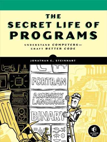
Figure 1-1 summarizes these Boolean operations graphically in what are known as truth tables. The inputs are outside of the boxes and the outputs are inside. In these tables, T stands for True and F stands for False.
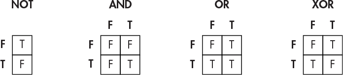
Figure 1-1: Truth tables for Boolean operations
Figure 1-2 shows how this works for the NOT and AND operations. We can find the output by tracing a path from the input or inputs.
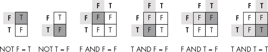
Figure 1-2: Using truth tables
As you can see, the NOT operation simply reverses the state of the input. On the other hand, the AND operation returns true only when both inputs are true.
NOTE
The XOR operation is built from other operations. For example, the XOR of 2 bits, a and b, is the same thing as (a OR b) AND NOT (a AND b). This shows that basic Boolean operations can be combined in different ways to yield the same result.
De Morgan’s Law
In the 1800s, British mathematician Augustus De Morgan added a law that applies only to Boolean algebra, the eponymous De Morgan’s law. This law states that the operation a AND b is equivalent to the operation NOT(NOT a OR NOT b), as shown in Figure 1-3.
Figure 1-3: The truth table for De Morgan’s law
Notice that the results of a AND b in the second column are identical to the results listed in the final NOT(NOT a OR NOT b) column. This means that with enough NOT operations, we can replace AND operations with OR operations (and vice versa). This is useful because computers operate on real-world input that’s not under their control. While it would be nice if inputs were of the form cold or raining, they’re often NOT cold or NOT raining. Similar to double negatives in languages such as English (“We didn’t not go skiing”), De Morgan’s law is a tool that lets us operate on these negative logic propositions in addition to the positive logic that we’ve already seen. Figure 1-4 illustrates the coat-wearing decision for both positive and negative logic forms.

Figure 1-4: Positive and negative logic
On the left (positive logic) side, we can make our decision using a single OR operation. On the right (negative logic) side, De Morgan’s law allows us to make our decision using a single AND operation. Without De Morgan’s law, we’d have to implement the negative logic case as NOT not-cold OR NOT not-raining. Although that works, there is a cost in price and performance to each operation, so minimizing operations minimizes costs. The hardware that performs the NOT operation costs real money and, as you’ll learn in the next chapter, cascading operations slows things down.
De Morgan tells us that this is equivalent to “cold and raining,” which is much simpler.
Representing Integers Using Bits
Let’s move up the food chain and learn how to use bits to represent numbers. Numbers are more complicated than logic but much simpler than words.
Representing Positive Numbers
We commonly use the decimal number system because it corresponds to our anatomy. Ten different symbols called digits can go into the containers: 0123456789. Containers are stacked right to left. Each container has a name that is separate from its contents; we call the rightmost container the ones, next is the tens, then the hundreds, thousands, and so on. These names are aliases for powers of 10; 100 is one, 101 is ten, 102 is one hundred, 103 is one thousand. This system is called base-10 since 10 is the base holding up the exponents. The value of a number is derived from the sum of the product of each container value and the value of its contents. For example, the number 5,028 is the sum of 5 thousands, 0 hundreds, 2 tens, and 8 ones, or 5 × 10³ + 0 × 102 + 2 × 101 + 8 × 100, as shown in Figure 1-5.

Figure 1-5: The number 5,028 in decimal notation
We can use a similar approach to make numbers using bits. Since we’re using bits instead of digits, we only have two symbols: 0 and 1. But that’s not a problem. In decimal, we add a container whenever we run out of room; we can fit a 9 in a single container but need two containers for 10. That works in binary too; we just need a new container for anything greater than a 1. The rightmost container would still be the ones, but what’s the next one? It’s the twos. The value of a container in decimal where there are 10 symbols is 10 times that of the one on the right. Thus, in binary where there are two symbols, the container value is two times that of the one on the right. That’s all there is to it! The container values are powers of 2, which means it’s a base-2 system instead of base-10.
Table 1-1 lists some of the powers of 2. We can use it as a reference to understand the binary representation of the number 5,028.
Table 1-1: Powers of 2
Expansion |
Power |
Decimal |
20 |
||
21 |
||
22 |
||
23 |
||
24 |
||
25 |
||
26 |
||
27 |
||
28 |
||
29 |
||
210 |
||
211 |
||
212 |
||
213 |
||
214 |
||
215 |
Each number in the far-right column of Table 1-1 represents the value of a binary container. Figure 1-6 shows how the number 5,028 can be written in binary, using essentially the same process that we used earlier for decimal notation.

Figure 1-6: The number 5,028 in binary
The result of the conversion to binary is:
1 × 212 + 0 × 211 + 0 × 210 + 1 × 29 + 1 × 28 + 1 × 27 + 0 × 26 + 1 × 25 + 0 × 24 + 0 × 23 + 1 × 22 + 0 × 21 + 0 × 20 = 5,028
As you can see, the number 5,028 in binary has one 4,096 (212), zero 2,048s (211), zero 1,024s (210), one 512 (29), one 256 (28), and so on to make up 1001110100100. Performing the same sort of calculation that we do for decimal numbers, we write 1 × 212 + 0 × 211 + 0 × 210 + 1 × 29 + 1 × 28 + 1 × 27 + 0 × 26 + 1 × 25 + 0 × 24 + 0 × 23 + 1 × 22 + 0 × 21 + 0 × 20. Substituting the decimal numbers from Table 1-1, we get 4,096 + 512 + 256 + 128 + 32 + 4, which is equal to 5,028.
We would say that 5,028 is a four-digit number in decimal. In binary it’s a 13-bit number.
The number of digits determines the range of values that we can represent in decimal. For example, 100 different values in the range 0–99 can be represented by two digits. Likewise, the number of bits determines the range of values we can represent in binary. For example, 2 bits can represent four values in the range 0–3. Table 1-2 summarizes both the number and range of values that we can represent with different numbers of bits.
Table 1-2: Ranges of Binary Number Values
Number of bits |
Number of values |
Range of values |
The rightmost bit in a binary number is called the least significant bit and the leftmost bit is called the most significant bit, because changing the value of the rightmost bit has the smallest effect on the value of the number and changing the value of the leftmost bit has the greatest effect. Computer people are fond of three-letter acronyms, or TLAs as we call them, so these are commonly referred to as the LSB and MSB. Figure 1-7 shows an example of the number 5,028 held in 16 bits.

Figure 1-7: MSB and LSB
You’ll notice that while the binary representation of 5,028 takes 13 bits, Figure 1-7 shows it in 16 bits. Just like in decimal, we can always use more containers than the minimum required by adding leading zeros on the left. In decimal, 05,028 has the same value as 5,028. Binary numbers are often represented this way because computers are built around blocks of bits.
Binary Addition
Now that you know how to represent numbers using binary, let’s look at how to do simple arithmetic with binary numbers. In decimal addition, we add up each digit from right (least significant digit) to left (most significant digit), and if the result is greater than 9, we carry the 1. Similarly, we add together each bit in a binary number, going from the least significant to the most significant bit, and if the result is greater than 1, we carry the 1.
Addition is actually a bit easier in binary because there are only 4 possible combinations of 2 bits compared to 100 combinations of 2 digits. For example, Figure 1-8 shows how to add 1 and 5 using binary numbers, showing the number being carried above each column.
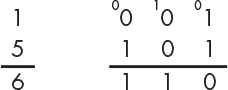
Figure 1-8: Binary addition
The number 1 is 001 in binary, while the number 5 is 101 because (1 × 4) + (0 × 2) + (1 × 1) = 5. To add the binary numbers 001 and 101 together, we start with the least significant bit in the rightmost column. Adding the binary numbers 1 and 1 in that column gives us 2, but we don’t have a symbol for 2 in binary. But we know that 2 is actually 10 in binary ([1 × 2] + [0 × 1] = 2), so we put 0 as the sum and carry the 1 to the next digit. Because the middle bits are zeros, we only have 1, which we carried over from before, as the sum. Then we add the digits in the leftmost column: 0 plus 1 is simply 1 in binary. The final result is the binary 110, or 6 in decimal notation, which is what you would get by adding 1 and 5.
You might notice that the rules for binary addition can be expressed in terms of the logical operations that we discussed previously, as Figure 1-9 illustrates. We’ll see in Chapter 2 that this is in fact how computer hardware does binary addition.
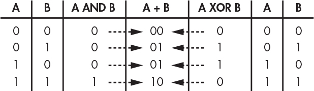
Figure 1-9: Binary addition using logical operations
When we add 2 bits together, the value of the result is the XOR of the 2 bits, and the value of the carry is the AND of the 2 bits. You can see that this is true in Figure 1-9, where adding 1 and 1 in binary results in 10. This means that the carry value is 1, which is what you get by performing the expression (1 AND 1). Likewise, the expression (1 XOR 1) yields 0, which is the value that we assign to the bit position itself.
Adding 2 bits is an operation that rarely happens in isolation. Referring back to Figure 1-8, it appears that we’re adding 2 bits together in each column, but we’re really adding 3 because of the carry. Fortunately, we don’t need to learn anything new to add 3 bits together (because A + B + C is the same as (A + B) + C, according to the associative rule), so we can add 3 bits together using a pair of 2-bit adds.
What happens when the result of addition doesn’t fit in the number of bits that we have? This results in overflow, which happens whenever we have a carry from the most significant bit. For example, if we have 4-bit numbers, and add 1001 (910) to 1000 (810), the result should be 10001 (1710), but it will end up being 0001 (110) because there’s no place for the most significant bit. As we’ll see in more detail later, computers have a condition code register, which is a place that holds odd pieces of information. One of these is an overflow bit, which holds the carry value from the most significant bit. We can look at this value to determine whether or not overflow occurred.
You’re probably aware that you can subtract one number from another by adding the negative of that number. We’ll learn how to represent negative numbers in the next section. Borrowing beyond the most significant bit is called underflow. Computers have a condition code for this too.
Representing Negative Numbers
All of the numbers we represented using binary in the last section were positive. But lots of real-world problems involve both positive and negative numbers. Let’s see how we can use bits to represent negative numbers. For example, let’s assume that we have 4 bits to play with. As you learned in the last section, 4 bits can represent 16 numbers in the range of 0 through 15. Just because we can hold 16 numbers in 4 bits doesn’t mean that those numbers have to be 0 through 15. Remember, language works through meaning and context. That means that we can devise new contexts in which we can interpret bits.
Sign and Magnitude
A sign is commonly used to distinguish negative numbers from positive ones. The sign has two values, plus and minus, so it can be represented using a bit. We’ll arbitrarily use the leftmost bit (MSB) for the sign, leaving us 3 bits that can represent a number between 0 and 7. If the sign bit is 0, we treat that number as positive. If it’s 1, we treat it as negative. This lets us represent 15 different positive and negative numbers in total, not 16, because there is both a positive 0 and a negative 0. Table 1-3 shows how this allows us to represent the numbers between –7 and +7.
This is called sign and magnitude representation because there’s a bit that represents a sign and bits that represent the magnitude, or how far the value is from zero.
Sign and magnitude representation is not used much for two reasons. First, bits cost money to build, so we don’t want to waste them by having two different representations for zero; we’d much rather use that bit combination to represent another number. Second, arithmetic using XOR and AND doesn’t work using this representation.
Table 1-3: Sign and Magnitude Binary Numbers
Sign |
22 |
21 |
20 |
Decimal |
0 |
1 |
1 |
1 |
+7 |
0 |
1 |
1 |
0 |
+6 |
0 |
1 |
0 |
1 |
+5 |
0 |
1 |
0 |
0 |
+4 |
0 |
0 |
1 |
1 |
+3 |
0 |
0 |
1 |
0 |
+2 |
0 |
0 |
0 |
1 |
+1 |
0 |
0 |
0 |
0 |
+0 |
1 |
0 |
0 |
0 |
–0 |
1 |
0 |
0 |
1 |
–1 |
1 |
0 |
1 |
0 |
–2 |
1 |
0 |
1 |
1 |
–3 |
1 |
1 |
0 |
0 |
–4 |
1 |
1 |
0 |
1 |
–5 |
1 |
1 |
1 |
0 |
–6 |
1 |
1 |
1 |
1 |
–7 |
Let’s say that we want to add +1 to –1. We’d expect to get 0, but using sign and magnitude representation we get a different result, as shown in Figure 1-10.
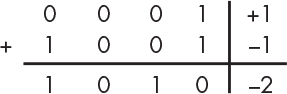
Figure 1-10: Sign and magnitude addition
As you can see, 0001 represents positive 1 in binary, because its sign bit is 0. The 1001 represents –1 in binary, because the sign bit is 1. Adding these together using XOR and AND arithmetic gives us 1010. This evaluates to –2 in decimal notation, which is not the sum of +1 and –1.
We could make sign and magnitude arithmetic work by using more complicated logic, but there’s value in keeping things as simple as possible. Let’s explore a few other ways of representing numbers to find a better approach.
One’s Complement
Another way to get negative numbers is to take positive numbers and flip all the bits, which is called one’s complement representation. We partition the bits in a manner similar to sign and magnitude. In this context, we get a complement using the NOT operation. Table 1-4 shows –7 through 7 using one’s complement.
Table 1-4: One’s Complement Binary Numbers
Sign |
22 |
21 |
20 |
Decimal |
0 |
1 |
1 |
1 |
+7 |
0 |
1 |
1 |
0 |
+6 |
0 |
1 |
0 |
1 |
+5 |
0 |
1 |
0 |
0 |
+4 |
0 |
0 |
1 |
1 |
+3 |
0 |
0 |
1 |
0 |
+2 |
0 |
0 |
0 |
1 |
+1 |
0 |
0 |
0 |
0 |
+0 |
1 |
1 |
1 |
1 |
–0 |
1 |
1 |
1 |
0 |
–1 |
1 |
1 |
0 |
1 |
–2 |
1 |
1 |
0 |
0 |
–3 |
1 |
0 |
1 |
1 |
–4 |
1 |
0 |
1 |
0 |
–5 |
1 |
0 |
0 |
1 |
–6 |
1 |
0 |
0 |
0 |
–7 |
As you can see, flipping each bit of 0111 (+7) yields 1000 (–7).
One’s complement representation still has the problem of two different representations for zero. It still doesn’t let us perform addition easily, either. To get around this, we use end-around carry to add 1 to the LSB if there is a carry out of the most significant position in order to get the correct result. Figure 1-11 illustrates how this works.

Figure 1-11: One’s complement addition
To add +2 and –1 using one’s complement, we perform binary addition of 0010 and 1110 as we would normally. Because adding the digits in the most significant bit (sign bit) results in 10, we bring down 0 and carry the 1 as the end-around carry for each digit. But we only have 4 bits to work with, so when we get to the MSB, we bring the carry back to the first bit to give us 0001, or +1, which is the correct sum of +2 and –1. As you can see, making this work adds a significant amount of complexity.
While this works, it still isn’t a great solution because we need additional hardware to add the end-around carry bit.
Neither sign and magnitude nor one’s complement representation is used in modern computers. Arithmetic using these methods doesn’t work without extra hardware, and extra hardware costs money. Let’s see if we can come up with a representation that solves this problem.
Two’s Complement
What would happen if we didn’t add any special hardware and just stuck with the XOR and AND operations? Let’s figure out what bit pattern, when added to +1, would result in 0 and call that –1. If we stick with 4-bit numbers, +1 is 0001. Adding 1111 to it results in 0000, as shown in Figure 1-12, so we’ll use that bit pattern to represent –1.

Figure 1-12: Finding –1
This is called two’s complement representation, and it’s the most commonly used binary representation for signed integers. We can obtain the negative of a number by complementing the number (that is, doing a NOT of each bit) and then adding 1, throwing away any carry from the MSB. The complement of +1, 0001, is 1110, and adding 1 gives us 1111 for –1. Likewise, +2 is 0010, its complement is 1101, and adding 1 gives us 1110 to represent –2. Table 1-5 shows –8 through 7 using two’s complement representation.
Table 1-5: Two’s Complement Binary Numbers
Sign |
22 |
21 |
20 |
Decimal |
0 |
1 |
1 |
1 |
+7 |
0 |
1 |
1 |
0 |
+6 |
0 |
1 |
0 |
1 |
+5 |
0 |
1 |
0 |
0 |
+4 |
0 |
0 |
1 |
1 |
+3 |
0 |
0 |
1 |
0 |
+2 |
0 |
0 |
0 |
1 |
+1 |
0 |
0 |
0 |
0 |
+0 |
1 |
1 |
1 |
1 |
–1 |
1 |
1 |
1 |
0 |
–2 |
1 |
1 |
0 |
1 |
–3 |
1 |
1 |
0 |
0 |
–4 |
1 |
0 |
1 |
1 |
–5 |
1 |
0 |
1 |
0 |
–6 |
1 |
0 |
0 |
1 |
–7 |
1 |
0 |
0 |
0 |
–8 |
Let’s try this using 0 to see if two’s complement fixes the issue of duplicate representations for zero. If we take 0000 and flip every bit, we get 1111 as its complement. Adding 1 to 1111 gives us [1]0000, but because this is a 5-bit number that exceeds the number of bits available to us, we can disregard the 1 in the carry bit. This leaves us with 0000, which is what we started with, so zero has only one representation in two’s complement.
Programmers need to know how many bits are required to hold the numbers they need. This will eventually become second nature. In the meantime, you can refer to Table 1-6, which shows the range of values that we can represent using two’s complement numbers of various sizes.
Table 1-6: Ranges of Two’s Complement Binary Number Values
Number of bits |
Number of values |
Range of values |
As you can see from Table 1-6, as the number of bits increases, the range of values that can be represented increases exponentially. It’s important to keep in mind that we always need context to determine whether a 4-bit number that we’re looking at is a 15 instead of a –1 using two’s complement, a –7 using sign and magnitude, or a –0 using one’s complement. You have to know which representation you’re using.
Representing Real Numbers
So far, we’ve managed to represent whole numbers using binary. But what about real numbers? Real numbers include a decimal point in base 10. We need some way to represent the equivalent binary point in base 2. Once again, this can be accomplished by interpreting bits in different contexts.
Fixed-Point Representation
One way to represent fractions using binary is by choosing an arbitrary place for a binary point, the binary equivalent of the decimal point. If we have 4 bits, for example, we can pretend that two of them are to the right of the binary point, representing four fractional values, and two are to the left, representing four whole values. This is called a fixed-point representation, because the location of the binary point is fixed. Table 1-7 shows how this would work.
Table 1-7: Fixed-Point Binary Numbers
Whole |
|
Fraction |
Value |
||
0 |
0 |
. |
0 |
0 |
0 |
0 |
0 |
. |
0 |
1 |
¼ |
0 |
0 |
. |
1 |
0 |
½ |
0 |
0 |
. |
1 |
1 |
¾ |
0 |
1 |
. |
0 |
0 |
1 |
0 |
1 |
. |
0 |
1 |
1¼ |
0 |
1 |
. |
1 |
0 |
1½ |
0 |
1 |
. |
1 |
1 |
1¾ |
1 |
0 |
. |
0 |
0 |
2 |
1 |
0 |
. |
0 |
1 |
2¼ |
1 |
0 |
. |
1 |
0 |
2½ |
1 |
0 |
. |
1 |
1 |
2¾ |
1 |
1 |
. |
0 |
0 |
3 |
1 |
1 |
. |
0 |
1 |
3¼ |
1 |
1 |
. |
1 |
0 |
3½ |
1 |
1 |
. |
1 |
1 |
3¾ |
The whole numbers to the left of the point should look familiar from binary notation. Similar to what we saw with integers, we have four values from the 2 bits to the right of the point; they represent fourths instead of the familiar tenths from decimal.
While this approach works pretty well, it’s not often used in general-purpose computers because it takes way too many bits to represent a useful range of numbers. Certain special-purpose computers, called digital signal processors (DSP), still use fixed-point numbers. And, as you’ll see in Chapter 11, fixed-point numbers are useful in certain applications.
General-purpose computers are built to solve general-purpose problems, which involve a wide range of numbers. You can get an idea of this range by skimming a physics textbook. For example, there are tiny numbers such as Planck’s constant (6.63 × 10⁻³⁴ joule-seconds) and huge numbers such as Avogadro’s constant (6.02 × 10²³ molecules/mole). This is a range of 1057, which comes out to about 2191. That’s almost 200 bits! Bits just aren’t cheap enough to use a few hundred of them to represent every number, so we need a different approach.
Floating-Point Representation
We solve this using a binary version of the scientific notation used to represent the wide range of numbers that includes Planck’s and Avogadro’s constants. Scientific notation represents a large range of numbers by (how else?) creating a new context for interpretation. It uses a number with a single digit to the left of the decimal point, called the mantissa, multiplied by 10 raised to some power, called the exponent. Computers use the same system, except that the mantissa and exponent are binary numbers and 2 is used instead of 10.
This is called floating-point representation, which is confusing because the binary (or decimal) point is always in the same place: between the ones and halves (tenths in decimal). The “float” is just another way of saying “scientific notation,” which allows us to write 1.2 × 10⁻³ instead of 0.0012.
Note that we don’t need any bits to indicate that the base is 2, because the floating-point definition says that it’s there by default. By separating the significant digits from the exponents, the floating-point system allows us to represent very small or very large numbers without having to store all those zeros.
Table 1-8 shows a 4-bit floating-point representation with 2 bits of mantissa and 2 bits of exponent.
Table 1-8: Floating-Point Binary Numbers
Mantissa |
|
Exponent |
Value |
||
0 |
0 |
. |
0 |
0 |
0 (0 × 20) |
0 |
0 |
. |
0 |
1 |
0 (0 × 21) |
0 |
0 |
. |
1 |
0 |
0 (0 × 21) |
0 |
0 |
. |
1 |
1 |
0 (0 × 23) |
0 |
1 |
. |
0 |
0 |
0.5 (½ × 20) |
0 |
1 |
. |
0 |
1 |
1.0 (½ × 21) |
0 |
1 |
. |
1 |
0 |
2.0 (½ × 22) |
0 |
1 |
. |
1 |
1 |
4.0 (½ × 23) |
1 |
0 |
. |
0 |
0 |
1.0 (1 × 20) |
1 |
0 |
. |
0 |
1 |
2.0 (1 × 21) |
1 |
0 |
. |
1 |
0 |
4.0 (1 × 22) |
1 |
0 |
. |
1 |
1 |
8.0 (1 × 23) |
1 |
1 |
. |
0 |
0 |
1.5 (1½ × 20) |
1 |
1 |
. |
0 |
1 |
3.0 (1½ × 21) |
1 |
1 |
. |
1 |
0 |
6.0 (1½ × 22) |
1 |
1 |
. |
1 |
1 |
12.0 (1½ × 23) |
While this example uses only a few bits, it reveals some inefficiencies present in this floating-point system. First, you’ll notice that there are a lot of wasted bit combinations. For example, there are four ways to represent 0 and two ways to represent 1.0, 2.0, and 4.0. Second, there aren’t bit patterns for every possible number; the exponent makes numbers farther apart as they get bigger. One of the side effects is that, while we can add 0.5 and 0.5 to get 1.0, we can’t add 0.5 and 6.0 because there’s no bit pattern that represents 6.5. (There is a whole subbranch of mathematics, called numerical analysis, that involves keeping track of how inaccurate calculations are.)
The IEEE Floating-Point Standard
Strange as it is, the floating-point system is the standard way to represent real numbers in computing. More bits are used than in Table 1-8, and there are two signs, one for the mantissa and a hidden one that is part of the exponent. There are also a lot of tricks to make sure that things like rounding work as well as possible and to minimize the number of wasted bit combinations. A standard called IEEE 754 spells all of this out. IEEE stands for the Institute of Electrical and Electronic Engineers, which is a professional organization whose activities include producing standards.
We want to maximize our precision given the available bits. One clever trick is called normalization, which adjusts the mantissa so that there are no leading (that is, on the left) zeros. Every left adjustment of the mantissa requires a corresponding adjustment of the exponent. A second trick, from Digital Equipment Corporation (DEC), doubles the accuracy by throwing away the leftmost bit of the mantissa since we know that it will always be 1, which makes room for one more bit.
You don’t need to know all of the gory details of IEEE 754 (yet). But you should know about two types of floating-point numbers that you’ll run into a lot: single precision and double precision. Single-precision numbers use 32 bits and can represent numbers approximately in the range ±10±38 with about 7 digits of accuracy. Double-precision numbers use 64 bits and can represent a wider range of numbers, approximately ±10±308, with about 15 digits of accuracy. Figure 1-13 shows how they’re laid out.
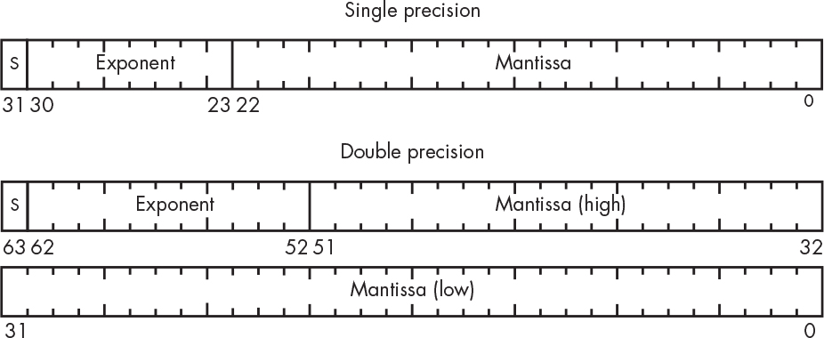
Figure 1-13: IEEE floating-point number formats
Both formats have a sign bit for the mantissa—the S in Figure 1-13. You can see that double-precision numbers have three more exponent bits than single precision, giving eight times the range. Double-precision numbers also have 29 more mantissa bits than single-precision ones, yielding greater accuracy. This all comes at the cost of taking twice as many bits as single-precision numbers, however.
You might have noticed that there is no explicit sign bit for the exponent. The designers of IEEE 754 decided that the exponent values of all 0s and all 1s would have special meaning so the actual exponent had to be crammed into the remaining bit patterns. They did this by using a biased (offset) exponent value. For single-precision numbers, the bias is 127, which means that the bit pattern for 127 (01111111) represents an exponent of 0. The bit pattern for 1 (00000001) represents an exponent of –126, and 254 (11111110) represents +127. Double precision is similar except that the bias is 1023.
One other handy part of IEEE 754 is that it has special bit patterns to represent things like division by zero, which evaluates to positive or negative infinity. It also specifies a special value called NaN, which stands for “not a number”—so if you find yourself in the NaNny state, it probably means that you did some illegal arithmetic operation. These special bit patterns use the reserved exponent values discussed previously.
Binary-Coded Decimal System
You’ve just seen some of the more common ways to represent numbers in binary, but there are many alternative systems. One is binary-coded decimal (BCD), in which we use 4 bits to represent each decimal digit. For example, the number 12 in binary is 1100. But in BCD, it’s 0001 0010, where 0001 represents 1 in the tens digit and 0010 represents 2 in the ones digit. This is a much more familiar and comfortable representation for people who are used to working in decimal.
Computers used to know how to operate on BCD numbers, but that system is no longer mainstream. However, it does crop up in many places, so it’s worth knowing about. In particular, many devices with which computers interact, such as displays and accelerometers, use BCD.
The main reason the BCD system has fallen out of favor is that it doesn’t use bits as efficiently as binary. You can see that BCD needs more bits than binary to represent a number. While bits are much cheaper than they used to be, they’re not so cheap that we want to throw away 6 out of every 16 bit combinations, as that would be equivalent to wasting a whopping 37.5 percent of available bits.
Easier Ways to Work with Binary Numbers
It’s a well-known fact that manipulating binary numbers leads to blindness; it can be visually exhausting! People have come up with a few ways to make binary numbers easier to read. We’ll look at a few of them here.
Octal Representation
One eyeball-friendly approach is octal representation. Octal means base-8, and the idea behind octal representation is to group bits in threes. As you should know by now, 3 bits can be used to represent 23, or eight values from 0 through 7. Let’s say that we have some monster binary number like 100101110001010100. This hurts my eyeballs. Figure 1-14 shows how to transform it into octal representation.

Figure 1-14: Octal representation of binary numbers
As you can see, we divide the bits into groups of three, and we assign the octal value to each group to get 456124, which is a lot easier to read. To get the octal value of 100, for example, we simply treat it as a binary number: (1 × 22) + (0 × 21) + (0 × 20) = 4.
Hexadecimal Representation
Octal representation is still in use, but not as widely as in the past. Hexadecimal representation (meaning base-16) has pretty much taken over because the insides of computers are built in multiples of 8 bits these days, which is evenly divisible by 4 but not by 3.
It was easy to repurpose some of the symbols from our familiar digits for binary because we needed only two of them, the 0 and 1. We needed only 8 of the 10 for octal. But we need 16 for hexadecimal, which is more than we have. We need a symbol to represent 10, another for 11, all the way up through 15. We make believe (I told you that we’d be doing that) that the symbols abcdef (or ABCDEF) represent the values 10 through 16. For example, let’s say we have another scary binary number like 11010011111111000001. Figure 1-15 shows how to convert it into hexadecimal.
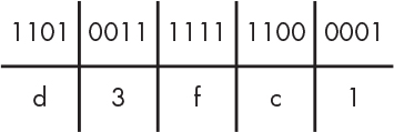
Figure 1-15: Hexadecimal representation of binary numbers
In this example, we divide the bits into groups of four. Then we assign one of the 16 symbol values (0123456789abcdef) to each group. For example, 1101 (the first group of 4 bits) would be d because it evaluates to 1(23) + 1(22) + 0(21) + 1(20) = 13 in decimal notation and d represents the number 13. We map the next group of 4 bits (0011) to another symbol, and so on. For example, 11010011111111000001 converts to d3fc1 in hexadecimal. Table 1-9 shows a handy list of hexadecimal values that you can refer to until they become second nature.
Table 1-9: Binary-to-Hexadecimal Conversion
Binary |
Hexadecimal |
Binary |
Hexadecimal |
0000 |
0 |
1000 |
8 |
0001 |
1 |
1001 |
9 |
0010 |
2 |
1010 |
a |
0011 |
3 |
1011 |
b |
0100 |
4 |
1100 |
c |
0101 |
5 |
1101 |
d |
0110 |
6 |
1110 |
e |
0111 |
7 |
1111 |
f |
Representing the Context
How do you know how to interpret a number? For example, the number 10 is 2 if it’s a binary number, 8 if it’s octal, 10 if it’s decimal, and 16 if it’s hexadecimal. Math books use subscripts, so we can use those to distinguish between them like this: 102, 108, 1010, or 1016. But subscripts are inconvenient to type on a computer keyboard. It would be nice if we could use a consistent notation, but unfortunately lots of people think they have a better way and keep inventing new ones. The following notations are used by many computer programming languages:
- A number that begins with a 0 is an octal number—for example, 017.
- A number that begins with one of the digits 1 through 9 is a decimal number—for example, 123.
- A number that’s prefixed with 0x is a hexadecimal number—for example, 0x12f.
Note that we can’t tell the difference between octal and decimal 0, but that’s not important because they have the same value. And few programing languages have a notation for binary because it really isn’t used very much anymore and can usually be determined by context. Some languages, such as C++, use a 0b prefix to represent binary numbers.
Naming Groups of Bits
Computers are not just unorganized buckets of bits. The people who design them have to make decisions about the number of bits and their organization for cost reasons. Just as with number representations, many ideas have been tried, and only some have survived.
Bits are too small a unit to be very useful, so they’re organized into larger chunks. For example, the Honeywell 6000 series of computers used 36-bit chunks as its basic organization and allowed those to be partitioned into 18-, 9-, or 6-bit chunks or combined into 72-bit chunks. The DEC PDP-8, the first commercial minicomputer (introduced in 1965), used 12-bit chunks. Over time the world has settled on 8-bit chunks as a fundamental unit, which we call a byte.
Chunks of different sizes have names to make them easier to reference. Table 1-10 summarizes the names and sizes of some of the common units in use today.
Table 1-10: Names for Bit Collections
Name |
Number of bits |
Nibble |
|
Byte |
|
Half word |
|
Long word |
|
Double word |
You might be wondering why we have half, long, and double words but no plain words. Word is used to describe the natural size of things in a particular computer design. The natural size refers to the largest chunk that can be operated on quickly. For example, although you could access bytes, half words, and long words on the DEC PDP-11, it had a 16-bit internal organization, making the natural size 16 bits. Programming languages such as C and C++ allow variables to be declared as int (short for integer), which makes them the natural size. You can also declare variables using a set of supported specific sizes.
There are some standard terms that make it easy to refer to big numbers. Well, there was a standard, and now it’s been replaced with a new one. Engineers have a habit of finding words that mean something close to what they want, and then using them as if they mean what they want. For example, in the metric system kilo means thousand, mega means million, giga means billion, and tera means trillion. These terms have been borrowed but changed a little because we use base-2 in computing instead of base-10. When we talk about a kilobit or kilobyte (K or KB) in computing, however, we don’t actually mean a thousand. We mean the closest thing to a thousand in base-2, which would be 1,024, or 210. The same goes for megabyte (M or MB), which is 220; giga (G or GB), which is 230; and tera (T or TB), which is 240.
But sometimes we do mean the base-10 version. You need to know the context in order to know which interpretation to apply. Traditionally, the base-10 version was used to refer to the size of disk drives. An American lawyer feigned ignorance about this and sued (Safier v. WDC), claiming that a disk drive was smaller than advertised. (In my opinion, this was just as dumb as the lawsuits claiming that 2 × 4 lumber doesn’t actually measure 2 inches by 4 inches, despite the fact that those have always been the dimensions of the unplaned, unfinished lumber.) This led to the creation of new IEC standard prefixes: kibi (KiB) for 210, mebi (MiB) for 220, gibi (GiB) for 230, and tebi (TiB) for 240. These are slowly catching on, although “kibis” sounds like dog food to me.
The term character is often used interchangeably with byte because, as we’ll see in the next section, characters’ codes have typically been designed to fit in bytes. Now, with better support for non-English languages, there’s often a need to talk about multibyte characters.
Representing Text
At this point, you’ve learned that bits are all we have to work with in computers and that we can use bits to represent other things, such as numbers. It’s time to take it to the next level and use numbers to represent other things, such as the letters and other symbols on your keyboard.
The American Standard Code for Information Interchange
There were several competing ideas for representing text, just like we saw for number representations. The winner, from back in 1963, is called the American Standard Code for Information Interchange (ASCII), which assigns 7-bit numeric values to all of the symbols on the keyboard. For example, 65 means capital A, 66 means capital B, and so on. The losing idea was IBM’s Extended Binary-Coded Decimal Interchange Code (EBCDIC), which was based on the encoding used for punched cards. And, yes, the “BCD” part of EBCDIC stands for the same binary-coded decimal that we saw earlier. Table 1-11 shows the ASCII code chart.
Table 1-11: ASCII Code Chart
Dec |
Hex |
Char |
Dec |
Hex |
Char |
Dec |
Hex |
Char |
Dec |
Hex |
Char |
0 |
00 |
NUL |
32 |
20 |
SP |
64 |
40 |
@ |
96 |
60 |
` |
1 |
01 |
SOH |
33 |
21 |
! |
65 |
41 |
A |
97 |
61 |
a |
2 |
02 |
STX |
34 |
22 |
“ |
66 |
42 |
B |
98 |
62 |
b |
3 |
03 |
ETX |
35 |
23 |
# |
67 |
43 |
C |
99 |
63 |
c |
4 |
04 |
EOT |
36 |
24 |
$ |
68 |
44 |
D |
100 |
64 |
d |
5 |
05 |
ENQ |
37 |
25 |
% |
69 |
45 |
E |
101 |
65 |
e |
6 |
06 |
ACK |
38 |
26 |
& |
70 |
46 |
F |
102 |
66 |
f |
7 |
07 |
BEL |
39 |
27 |
’ |
71 |
47 |
G |
103 |
67 |
g |
8 |
08 |
BS |
40 |
28 |
( |
72 |
48 |
H |
104 |
68 |
h |
9 |
09 |
HT |
41 |
29 |
) |
73 |
49 |
I |
105 |
69 |
i |
10 |
0A |
NL |
42 |
2A |
* |
74 |
4A |
J |
106 |
6A |
j |
11 |
0B |
VT |
43 |
2B |
+ |
75 |
4B |
K |
107 |
6B |
k |
12 |
0C |
FF |
44 |
2C |
, |
76 |
4C |
L |
108 |
6C |
l |
13 |
0D |
CR |
45 |
2D |
- |
77 |
4D |
M |
109 |
6D |
m |
14 |
0E |
SO |
46 |
2E |
. |
78 |
4E |
N |
110 |
6E |
n |
15 |
0F |
SI |
47 |
2F |
/ |
79 |
4F |
O |
111 |
6F |
o |
16 |
10 |
DLE |
48 |
30 |
0 |
80 |
5 |
P |
112 |
70 |
p |
17 |
11 |
DC1 |
49 |
31 |
1 |
81 |
51 |
Q |
113 |
71 |
q |
18 |
12 |
DC2 |
50 |
32 |
2 |
82 |
52 |
R |
114 |
72 |
r |
19 |
13 |
DC3 |
51 |
33 |
3 |
83 |
53 |
S |
115 |
73 |
s |
20 |
14 |
DC4 |
52 |
34 |
4 |
84 |
54 |
T |
116 |
74 |
t |
21 |
15 |
NAK |
53 |
35 |
5 |
85 |
55 |
U |
117 |
75 |
u |
22 |
16 |
SYN |
54 |
36 |
6 |
86 |
56 |
V |
118 |
76 |
v |
23 |
17 |
ETB |
55 |
37 |
7 |
87 |
57 |
W |
119 |
77 |
w |
24 |
18 |
CAN |
56 |
38 |
8 |
88 |
58 |
X |
120 |
78 |
x |
25 |
19 |
EM |
57 |
39 |
9 |
89 |
59 |
Y |
121 |
79 |
y |
26 |
1A |
SUB |
58 |
3A |
: |
90 |
5A |
Z |
122 |
7A |
z |
27 |
1B |
ESC |
59 |
3B |
; |
91 |
5B |
[ |
123 |
7B |
{ |
28 |
1C |
FS |
60 |
3C |
< |
92 |
5C |
124 |
7C |
| |
|
29 |
1D |
GS |
61 |
3D |
= |
93 |
5D |
] |
125 |
7D |
} |
30 |
1E |
RS |
62 |
3E |
> |
94 |
5E |
^ |
126 |
7E |
~ |
31 |
1F |
US |
63 |
3F |
? |
95 |
5F |
_ |
127 |
7F |
DEL |
Let’s find the letter A in this table. You can see that it has a decimal value of 65, which is 0x41 in hexadecimal—that’s also 0101 in octal. As it turns out, ASCII character codes are one place where octal is still used a lot, for historical reasons.
You’ll notice a lot of funny codes in the ASCII table. They’re called control characters because they control things as opposed to printing. Table 1-12 shows what they stand for.
Table 1-12: ASCII Control Characters
NUL |
null |
SOH |
start of heading |
STX |
start of text |
ETX |
end of text |
EOT |
end of transmission |
ENQ |
enquiry |
ACK |
acknowledge |
BEL |
bell |
BS |
backspace |
HT |
horizontal tab |
NL |
new line |
VT |
vertical tab |
FF |
form feed |
CR |
carriage return |
SO |
shift out |
SI |
shift in |
DLE |
data link escape |
DC1 |
device control #1 |
DC2 |
device control #2 |
DC3 |
device control #3 |
DC4 |
device control #4 |
NAK |
negative acknowledgment |
SYN |
synchronous idle |
ETB |
end of transmission block |
CAN |
cancel |
EM |
end of medium |
SUB |
substitute |
ESC |
escape |
FS |
file separator |
GS |
group separator |
RS |
record separator |
US |
unit separator |
SP |
space |
DEL |
delete |
Many of these were intended for communications control. For example, ACK (acknowledgment) means “I got the message,” and NAK (negative acknowledgment) means “I didn’t get the message.”
The Evolution of Other Standards
ASCII worked for a while because it contained the characters necessary for the English language. Most of the early computers were American, and the ones that weren’t were British. The need to support other languages grew as computers became more widely available. The International Standards Organization (ISO) adopted ISO-646 and ISO-8859, which are basically ASCII with some extensions for the accent symbols and other diacritical marks used in European languages. The Japanese Industrial Standards (JIS) committee came up with JIS X 0201 for Japanese characters. There are also Chinese standards, Arabic standards, and more.
One reason for all of the different standards is that they were created at a time when bits were a lot more expensive than they are today, so characters were packed into 7 or 8 bits. As the price of bits began to fall, a newer standard called Unicode was crafted that assigned 16-bit codes to characters. At the time, it was believed that 16 bits would be enough to hold all of the characters in all languages on Earth with room to spare. Unicode has since been extended to 21 bits (of which 1,112,064 values are valid), which we think will do the job, but even that might not last given our propensity to create new cat emojis.
Unicode Transformation Format 8-bit
Computers use 8 bits to store an ASCII character because they’re not designed to handle 7-bit quantities. Again, while bits are a whole lot cheaper than they used to be, they’re not so cheap that we want to use 16 of them to store a single letter when we can get by with using just 8. Unicode addresses this problem by having different encodings for the character codes. An encoding is a bit pattern that represents another bit pattern. That’s right—we’re using abstractions like bits to create numbers that represent characters and then using other numbers to represent those numbers! You see what I meant by make-believe? There’s one encoding in particular called Unicode Transformation Format–8 bit (UTF-8), invented by American computer scientist Ken Thompson and Canadian programmer Rob Pike, that we use most commonly for its efficiency and backward compatibility. UTF-8 uses 8 bits for each ASCII character so that it doesn’t consume any additional space for ASCII data. It encodes non-ASCII characters in a way that doesn’t break programs that expect ASCII.
UTF-8 encodes characters as a sequence of 8-bit chunks, often called octets. A clever aspect of UTF-8 is that the number of most significant ones in the first chunk yields the length of the sequence, and it’s easy to recognize the first chunk. This is useful because it allows programs to easily find character boundaries. The ASCII characters all fit in 7 bits, so they take one chunk apiece, which is pretty convenient for us English speakers because it’s more compact than for other languages that need non-ASCII symbols. Figure 1-16 illustrates how UTF-8 encodes characters compared to Unicode.

Figure 1-16: Examples of UTF-8 encoding
In Figure 1-16, we can see that the numeric code for the letter A is identical in ASCII and Unicode. To encode A in UTF-8, we say that whatever codes that fit in 7 bits get a single UTF-8 chunk with the MSB set to 0. This is why there’s a leading 0 in the UTF-8 for the letter A. Next we see the Unicode for the π symbol, which does not fit in 7 bits but does fit into 11. To encode π in UTF-8, we use two 8-bit chunks with the first chunk starting with 110 and the second with 10, which leaves 5 and 6 bits left over in each chunk respectively to hold the remaining code. Finally, we see the Unicode for ♣, which fits in 16 bits and so takes three UTF-8 chunks.
Using Characters to Represent Numbers
UTF-8 uses numbers to represent numbers that represented numbers made from bits that represented characters. But we’re not done yet! Now we’re going to use characters to represent some of those numbers. People wanted to send more than text between computers in the early days of computer-to-computer communication; they wanted to send binary data. But doing this wasn’t straightforward because, as we saw earlier, many of the ASCII values were reserved for control characters, and they weren’t handled consistently between systems. Also, some systems supported transmission of only 7-bit characters.
Quoted-Printable Encoding
Quoted-Printable encoding, also known as QP encoding, is a mechanism that allows 8-bit data to be communicated over a path that only supports 7-bit data. It was created for email attachments. This encoding allows any 8-bit byte value to be represented by three characters: the character = followed by a pair of hexadecimal numbers, one for each nibble of the byte. Of course, in doing this, the = now has special meaning and so must be represented using =3D, its value from Table 1-11.
Quoted-Printable encoding has a few extra rules. The tab and space characters must be represented as =09 and =20, respectively, if they occur at the end of a line. Lines of encoded data can’t be more than 76 characters in length. An = at the end of a line is a soft line break that is removed when the data is decoded by the recipient.
Base64 Encoding
While Quoted-Printable encoding works, it’s not very efficient because it takes three characters to represent a byte. Base64 encoding is more efficient, which was really important when computer-to-computer communication was much slower than it is today. Base64 encoding packs 3 bytes of data into 4 characters. The 24 bits of data in the three bytes is partitioned into four 6-bit chunks, each of which is assigned a printing character, as shown in Table 1-13.
Table 1-13: Base64 Character Encoding
Number |
Character |
Number |
Character |
Number |
Character |
Number |
Character |
0 |
A |
16 |
Q |
32 |
g |
48 |
w |
1 |
B |
17 |
R |
33 |
h |
49 |
x |
2 |
C |
18 |
S |
34 |
i |
50 |
y |
3 |
D |
19 |
T |
35 |
j |
51 |
z |
4 |
E |
20 |
U |
36 |
k |
52 |
0 |
5 |
F |
21 |
V |
37 |
l |
53 |
1 |
6 |
G |
22 |
W |
38 |
m |
54 |
2 |
7 |
H |
23 |
X |
39 |
n |
55 |
3 |
8 |
I |
24 |
Y |
40 |
o |
56 |
4 |
9 |
J |
25 |
Z |
41 |
p |
57 |
5 |
10 |
K |
26 |
a |
42 |
q |
58 |
6 |
11 |
L |
27 |
b |
43 |
r |
59 |
7 |
12 |
M |
28 |
c |
44 |
s |
60 |
8 |
13 |
N |
29 |
d |
45 |
t |
61 |
9 |
14 |
O |
30 |
e |
46 |
u |
62 |
+ |
15 |
P |
31 |
f |
47 |
v |
63 |
/ |
The bytes 0, 1, 2 would be encoded as AAEC. Figure 1-17 shows how this is accomplished.

Figure 1-17: Base64 encoding
This encoding converts every set of 3 bytes to four characters. But there’s no guarantee that the data will be a multiple of 3 bytes in length. This is solved with padding characters; a = would be tacked on to the end if there were only 2 bytes at the end and == if there were only 1 byte.
This encoding is still commonly used for email attachments.
URL Encoding
You saw above that the Quoted-Printable encoding gave special power to the = character, and that the encoding included a mechanism for representing the = without its special powers. An almost identical scheme is used in web page URLs.
If you’ve ever examined a web page URL, you may have noticed character sequences such as %26 and %2F. These exist because certain characters have special meaning in the context of a URL. But sometimes we need to use those characters as literals—in other words, without those special meanings.
As we saw in the last section, characters are represented as a sequence of 8-bit chunks. Each chunk can be represented by two hexadecimal characters, as Figure 1-16 demonstrated. URL encoding, also known as percent-encoding, replaces a character with a % followed by its hexadecimal representation.
For example, the forward slash character (/) has special meaning in a URL. It has an ASCII value of 47, which is 2F in hex. If we need to use a / in a URL without triggering its special meaning, we replace it with %2F. (And because we’ve just given a special meaning to the % character, it needs to be replaced by %25 if we literally mean %.)
Representing Colors
Another common use of numbers is to represent colors. You already know that numbers can be used to represent coordinates on a graph. Computer graphics involves making pictures by plotting blobs of color on the equivalent of electronic graph paper. The blob plotted at each coordinate pair is called a picture element or, more commonly, pixel.
Computer monitors generate color by mixing red, green, and blue lights using the aptly named RGB color model. The colors can be represented by a color cube, in which each axis represents a primary color, as shown in Figure 1-18. A value of 0 means that a particular light is off, and 1 means that it’s as bright as it can get.

Figure 1-18: An RGB color cube
You can see that the color is black if no lights are on and white if all of the lights are fully up, meaning they’re at maximum brightness. A shade of red results if only the red light is on. Mixing red and green creates yellow. Gray results from setting all three lights to the same level. This way of mixing colors is called an additive color system, as adding the primaries produces different colors. Figure 1-19 shows the coordinates of a few colors in the color cube.
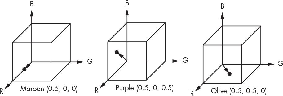
Figure 1-19: RGB color cube examples
If you’ve tried your hand at painting, you’re probably more familiar with a subtractive color system, in which the primaries are cyan, magenta, and yellow. A subtractive color system produces colors by removing wavelengths from white light rather than by adding colored light as in the additive system. While neither color system can produce all of the colors that your eye can see, the subtractive system can produce more than the additive system. A whole set of prepress technologies exists to make it possible for artists to work on computer monitors and still have their designs look correct when printed in magazines. If you’re really interested in color, read A Field Guide to Digital Color by Maureen Stone.
The human eye is a very messy piece of machinery that evolved for survival, not computing. It can distinguish around 10 million colors, but it’s not linear; doubling the light level doesn’t necessarily translate to doubling perceived brightness. Even worse, the eye’s response changes slowly over time in response to overall light level. This is called dark adaptation. And the response is different for different colors; the eye is very sensitive to changes in green but relatively insensitive to changes in blue, a phenomenon that was exploited in the National Television System Committee (NTSC) standard. Modern computers have settled on rounding up 10 million to the nearest power of 2 and using 24 bits to represent color. These 24 bits are divided up into three 8-bit fields, one for each of the color primaries.
You might have noticed that there is no name for 24 bits in Table 1-10. That’s because modern computers aren’t designed to operate on 24-bit units (although there were a few 24-bit machines, such as the Honeywell DDP-224). As a result, colors get packed into the nearest standard size, which is 32 bits (long word), as shown in Figure 1-20.

Figure 1-20: RGB color packing
You can see that this scheme leaves 8 unused bits for every color. That’s a lot, considering that computer monitors today have in excess of 8 million pixels. We can’t just let those bits go to waste, so what can we do with them? The answer is that we can use them for something that’s missing from our discussion of color above: transparency, meaning how much you can “see through” the color. So far, we’ve only discussed opaque colors, but those can’t be used for rose-colored glasses, for example.
Adding Transparency
In early animated movies, each frame was drawn by hand. Not only was this very labor-intensive, but there was also a lot of visual “jitter,” because it was impossible to exactly reproduce the background on each frame. American animators John Bray (1879–1978) and Earl Hurd (1880–1940) solved this problem with their invention of cel animation in 1915. In cel animation, moving characters were drawn on transparent sheets of celluloid, which could then be moved over a static background image.
Although computer animation traces its roots back to the 1940s, it really took off in the 1970s and 1980s. Computers weren’t fast enough back then to do everything that movie directors wanted (and likely never will be because, well, directors). And a mechanism was needed to combine objects generated by different algorithms. Like cel animation, transparency allows for compositing, or combining together images from different sources. You’re probably familiar with this concept if you’ve ever played with an image editor like GIMP or Photoshop.
In 1984, Tom Duff and Thomas Porter at Lucasfilm invented a way to implement transparency and compositing that has since become standard. They added a transparency value called alpha (α) to each pixel. The α is a mathematical value between 0 and 1, where 0 means that a color is completely transparent and 1 means that a color is completely opaque. A set of compositing algebra equations define how colors with different alphas combine to produce new colors.
Duff and Porter’s implementation is clever. Since they’re not using a floating-point system, they represent an α value of 1 using 255, taking advantage of those extra 8 bits in Figure 1-20. Rather than storing red, green, and blue, Duff and Porter store the color values multiplied by α. For example, if the color were medium red, it would have a value of 200 for red and 0 for green and blue. The red value would be 200 if it were opaque because the α would be 1 (with an α value represented by 255). But the α of a medium red color that was half transparent would be 0.5, so the stored value for red would be 200 × 0.5 = 100 and the stored α would be 127 (255 × 0.5 = 127). Figure 1-21 shows the storage arrangement for pixels with α.

Figure 1-21: RGBα color packing
Compositing images, therefore, involves multiplying the color values by α. Storing colors in premultiplied form means we don’t have to do these multiplications every time a pixel is used.
Encoding Colors
Because web pages are primarily text documents, meaning they’re a sequence of human-readable characters often in UTF-8, we need a way of representing colors using text.
We do this in a manner similar to URL encoding, specifying colors using hex triplets. A hex triplet is a # followed by six hexadecimal values formatted as #rrggbb where rr is the red value, gg is the green value, and bb is the blue value. For example, #ffff00 would be yellow, #000000 would be black, and #ffffff would be white. Each of the three 8-bit color values is converted to a two-character hexadecimal representation.
Although α is also available in web pages, there is no concise format for its representation. It uses yet another set of schemes entirely.
Summary
In this chapter, you learned that although bits are conceptually simple, they can be used to represent complex things like very large numbers, characters, and even colors. You learned how to represent decimal numbers in binary, perform simple arithmetic using binary numbers, and represent negative numbers and fractions. You also learned different standards for encoding letters and characters using bits.
There’s a geek joke that goes, “There are 10 types of people in the world—those who understand binary and those who don’t.” You should now be in the first of those categories.
In Chapter 2, you’ll learn some hardware basics that will help you understand the physical components of a computer and why computers use bits in the first place.