
CHAPTER 5
Developing Drawing Strategies: Part 2
The preceding chapter emphasized using existing geometry (or objects) in a drawing to create new geometry. In this chapter, you'll look at new tools for forming an efficient drawing strategy. Before getting back to the cabin, I'll give you a brief overview of the tools available for starting and running commands.
In this chapter, you will learn to
- Use running object snaps
- Use Polar Tracking
- Use the STRETCH command
- Use point filters
- Zoom and pan with the Realtime commands
- Copy and move objects
- Use direct entry for distances
- Create circles and ellipses
- Draw using parametric constraints
Starting and Running Commands
Developing a drawing strategy begins with determining the best way to start a command and when to start it. The Autodesk® AutoCAD® program provides several ways to start most of the commands you'll be using. As you have seen, you can start the OFFSET, FILLET, TRIM, and EXTEND commands from either the Ribbon's Home tab ![]() Modify panel or by typing the first letter or two of the command and then pressing
Modify panel or by typing the first letter or two of the command and then pressing ![]() . You can also display the menu bar and access commands from a drop-down list or expose the Modify toolbar and choose the tools from it.
. You can also display the menu bar and access commands from a drop-down list or expose the Modify toolbar and choose the tools from it.
You'll determine when to use the Ribbon, menu bar, toolbars, or keyboard based on what you're doing at the time, as well as by your personal preference. The purpose of the Ribbon is to make the most frequently used tools readily available, but keyboard entry can also be a fast method when you are using the command aliases. The menus are slower to use because they require more selections to get to a command, but they also contain more commands and options than the toolbars, as well as some commands not found on the Ribbon.
Remember that, if you have just ended a command, you can restart that command by pressing ![]() , by pressing the spacebar, or by right-clicking. When you right-click, a context menu appears near the cursor. The top item on this menu is Repeat Command, where Command is the last command used. For example, if you've just finished using the ERASE command and you right-click, the top item of the context menu is Repeat Erase. If you've used a command recently, you can select that command by pausing the cursor (hovering) over the Recent Input option and then selecting that command from the cascading menu that appears (see Figure 5.1).
, by pressing the spacebar, or by right-clicking. When you right-click, a context menu appears near the cursor. The top item on this menu is Repeat Command, where Command is the last command used. For example, if you've just finished using the ERASE command and you right-click, the top item of the context menu is Repeat Erase. If you've used a command recently, you can select that command by pausing the cursor (hovering) over the Recent Input option and then selecting that command from the cascading menu that appears (see Figure 5.1).
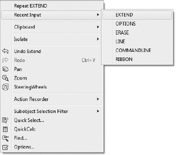
FIGURE 5.1 The right-click context menu and Recent Input cascading menu
ACCESSING COMMANDS FROM THE KEYBOARD
Here's a quick recap of the methods you've used so far to run commands from the keyboard. To start the OFFSET command from the keyboard, enter O![]() . To start the FILLET command, enter F
. To start the FILLET command, enter F![]() . To start the TRIM command, enter TR
. To start the TRIM command, enter TR![]() ; and to start the EXTEND command, enter EX
; and to start the EXTEND command, enter EX![]() . AutoCAD employs this same framework for nearly all of its commands; start commands by entering the entire name of the command (EXTEND
. AutoCAD employs this same framework for nearly all of its commands; start commands by entering the entire name of the command (EXTEND![]() ), or enter the starting characters of the command (EX
), or enter the starting characters of the command (EX![]() ).
).
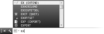
The autocomplete feature allows for efficient access to commands and, when available, the associated command alias. Pausing after entering one or more characters at the command line will display a list of commands whose prefix matches what you've typed. (The following illustration shows the autocomplete feature displaying a list of commands whose prefix matches EX.) With this list open, you can continue entering the command name or select it from the list.
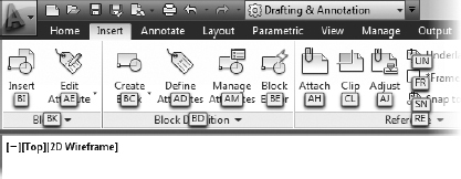
Another way to access commands from the keyboard is to press the F10 or Alt key. When you hold down the Alt key for a second or two, AutoCAD will display a series of shortcuts across the Ribbon. Entering these one- and two-character shortcuts will allow you to navigate the Ribbon without using a mouse. For example, to start a command on the Insert Ribbon tab, press Alt and then enter IN followed by a second two-character code indicated by the cue cards, as shown in the following illustration. These shortened command entries can range from a single character to several characters and are known as command aliases.
![]() NOTE Throughout the rest of the book, I'll introduce some of the other items on the context menu. This menu is called a context menu because different items are displayed on it, depending on whether a command is running, which command you're using, and where you are in a command.
NOTE Throughout the rest of the book, I'll introduce some of the other items on the context menu. This menu is called a context menu because different items are displayed on it, depending on whether a command is running, which command you're using, and where you are in a command.
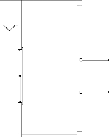
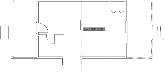
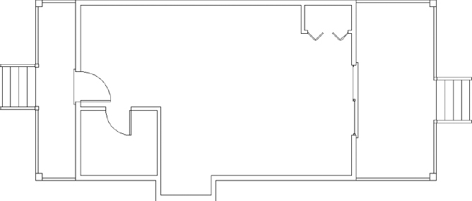
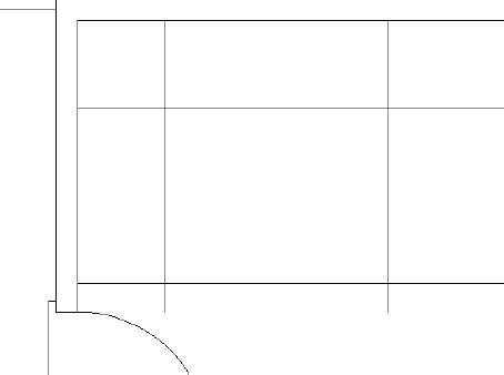
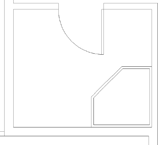
In this chapter, I'll introduce you to several new commands and, through the step-by-step instructions, show you some alternative methods for accomplishing tasks similar to those you have already completed. You'll add front and back decks and steps, thresholds, and kitchen and bath fixtures to the cabin floor plan (see Figure 5.2). For each of these tasks, the focus will be on making your job easier by utilizing objects and geometry that are already in the drawing and on using the appropriate tools to help you accomplish tasks more quickly and efficiently.
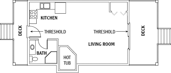
FIGURE 5.2 The cabin with front and back decks and steps, thresholds, kitchen, and bathroom
![]() If you haven't already done so, activate the Dynamic Input button on the status bar and work with the dynamic display information shown in the drawing area as you work your way through the chapter.
If you haven't already done so, activate the Dynamic Input button on the status bar and work with the dynamic display information shown in the drawing area as you work your way through the chapter.
Drawing the Thresholds
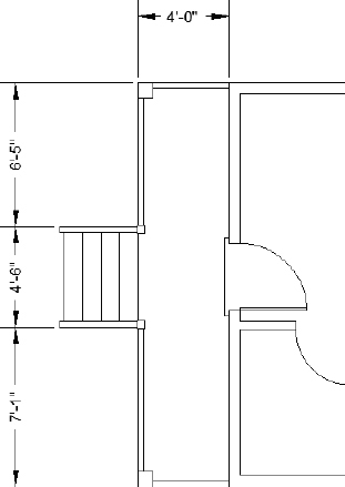
To get started, let's take a look at the two thresholds. Each threshold is represented with three simple lines. You could certainly manually draw these lines with the skills you've learned so far, but we want to find the most efficient way. The trick will be to see which part of the drawing you can effectively use to generate and position those lines. As illustrated in Figure 5.3, the thresholds extend 2″ (51 mm) beyond the outside wall line and run 3″ (76 mm) past either jamb line.
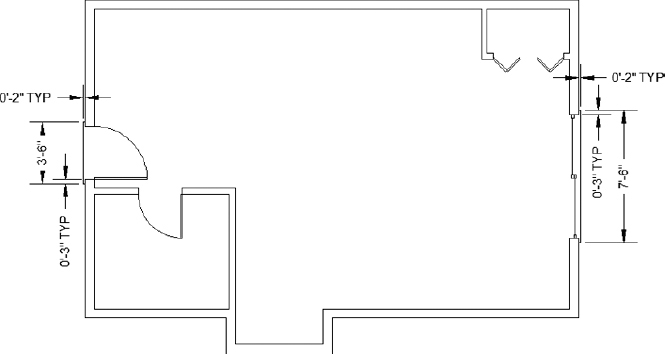
FIGURE 5.3 The thresholds with their dimensions
Drawing the Front Threshold
Thresholds generally are used on doorway openings when the level changes from one side of the opening to the other or to prevent rain and dust from entering the structure. This usually occurs at entrances that open from or to the outside. Although they are quite different in shape, each threshold for the cabin has the same geometry as the steps. The lip of each threshold is offset 2′ (51 mm) from the outside wall, and each edge runs 3″ (76 mm) past the doorjamb (see Figure 5.3). You'll use a temporary tracking point with Polar Tracking and direct entry to draw the three thresholds for the cabin.
As you can see in Figure 5.3, the front threshold is 7′-6″ (2286 mm) wide, extending 3″ (76 mm) past the doorway on each side. You can draw a line from the endpoint of one of the jamb lines down 3″ (76 mm) and then draw the perimeter of the threshold. Here's how you do it:
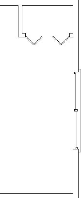
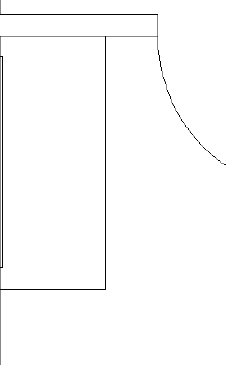
- With AutoCAD running, open your cabin drawing I04A-FPLAYO.dwg (M04A-FPLAYO.dwg), and use the ZOOM command options to achieve a view similar to Figure 5.4. The file is also available from this book's web page at www.sybex.com/go/autocad2013ner.
- Check to make sure that all buttons on the left side of the status bar, except Ortho Mode, Object Snap, and Dynamic Input, are still in their off positions.
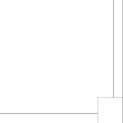
FIGURE 5.4 Zoomed in to the front opening
- Start the LINE command.
You need to start the threshold 3″ (76 mm) below the bottom jamb, and in line with the outside wall line. Unfortunately, there is no feature to snap the cursor to at that point. The techniques that you've previously used would require offsetting the jamb line or starting the line at the jamb and drawing an overlapping line 3″ (76 mm) downward. Both of these methods would require you to erase the unnecessary line after the threshold is complete.
Instead of wasting time drawing and then erasing lots of unnecessary line work, you will begin using the Object Snap Tracking tool. This tool will help eliminate the need to create unnecessary geometry. Using the Object Snap Tracking tool requires you to specify a location in the drawing area, called a temporary tracking point, relative to existing features or other locations.
 Click the Object Snap Tracking button on the status bar. In this case, because the threshold starts 3″ (76 mm) below the outside corner of the lower jamb, you'll use that corner as the temporary tracking point for the start point of the line.
- Pause the cursor over the outside corner of the lower jamb until the Endpoint osnap marker appears. A small, green cross displays inside the Endpoint osnap marker.
WAYS TO USE THE OBJECT SNAP TOOLS
You can access the Object Snap tools in several ways:
- The Object Snap context menu provides access to the object snaps. To open this menu, hold down the Shift key or Ctrl key and right-click.
- If you're using a mouse with a scroll wheel or a three-button mouse, you might be able to open the Object Snap menu by clicking the wheel or the middle mouse button. If this doesn't work, set the MBUTTONPAN variable to zero (enter MBUTTONPAN
 O). Be aware that you will no longer be able to pan by holding down the scroll wheel.
 - When the menu bar is displayed, the Object Snap toolbar can be displayed from the Tools menu
 Toolbars AutoCAD Object Snap.
 - In most cases, you can enter the first three letters of an osnap to activate it, as in END for Endpoint.
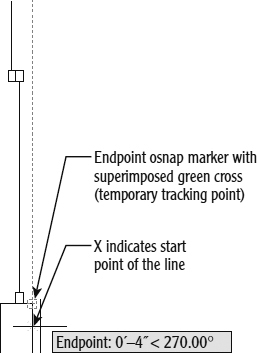
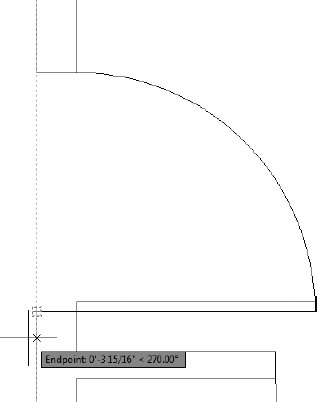
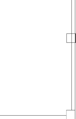
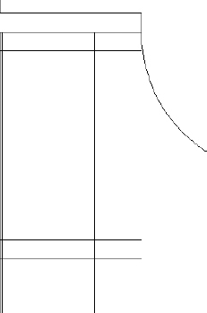
- Move the cursor directly downward, and you will see an X appear at the cursor, directly below the reference point (see Figure 5.5).
FIGURE 5.5 Pause the cursor over the endpoint to select the reference point.
The green cross indicates the temporary tracking point for the Object Snap Tracking tool, and the X indicates the point where the line will start.
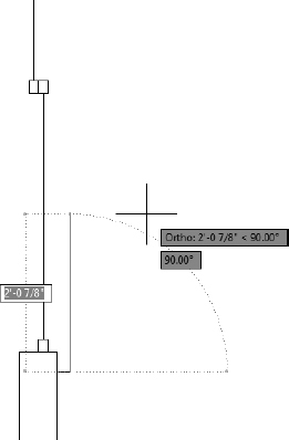
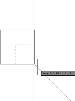
- Enter 3 (76) to use the direct entry method to start the first line 3″ (76 mm) below the temporary tracking point. With the Ortho mode turned on, the point selected is directly below the corner of the jamb.
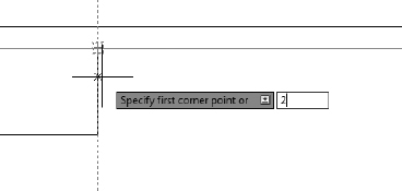
- Hold the crosshair cursor directly to the right of the last point; when you see the alignment path and tooltip, enter 2 (51), as shown in Figure 5.6.
FIGURE 5.6 Using direct input to draw the bottom edge of the threshold
AutoCAD draws the bottom edge of the threshold. You used direct entry with Ortho mode again, and you didn't have to enter the relative polar or the Cartesian coordinates.
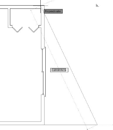
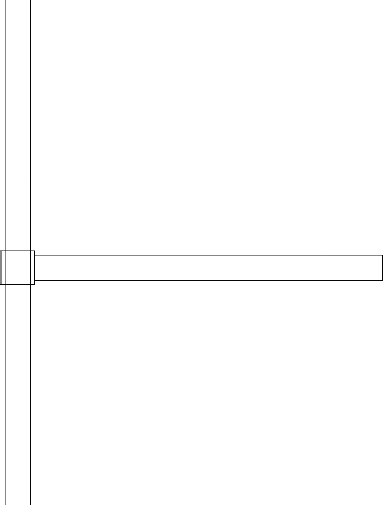
- Hold the crosshair cursor directly above the last point; when you see the alignment path and tooltip, enter 7′6″ (2286). AutoCAD draws the front edge of the threshold.
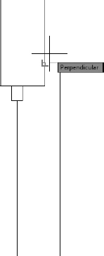
- Select Perpendicular from the Object Snap context menu (Shift+right-click) and move the cursor to the outside wall line. Alternatively, you can enter PER at the command line to enable the Perpendicular osnap.
- When the Perpendicular icon appears on the wall line, as shown in Figure 5.7, click to draw the top edge of the threshold.
FIGURE 5.7 Use the Perpendicular osnap to draw the final line.
- Press to end the LINE command.
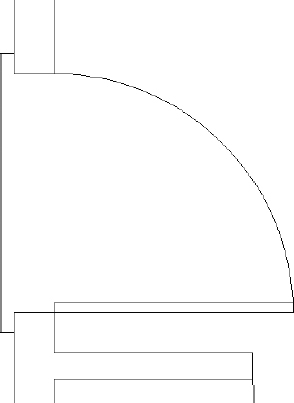
The completed front threshold looks like Figure 5.8.
FIGURE 5.8 Completing the front threshold
 TIP When using object snaps to locate points within a drawing, you do not need to select the osnap icon itself. Notice how the cursor in Figure 5.7 is located slightly above and to the right of the point AutoCAD found by using the Perpendicular object snap. Regardless of where you select, a perpendicular line will be drawn to the point highlighted by the Perpendicular osnap icon.
 - Use the Zoom Extents (ZOOM) command to view the completed front threshold with the whole floor plan. Remember, by default, double-clicking the middle button on a wheel mouse performs a Zoom Extents (ZOOM) command.
- Save your drawing as I05-01-FrontThreshold.dwg (M05-01-FrontThreshold.dwg) by choosing Application menu Save As AutoCAD Drawing.
Drawing the Back Threshold
The method of drawing the threshold for the back door is the same as the method used to draw the front threshold. You will use Ortho mode, direct input, and Object Snap Tracking to draw the lines. Here is how it's done:
- Make sure I05-01-FrontThreshold.dwg (M05-01-FrontThreshold.dwg) is open.
- Zoom and pan until the back door fills the drawing area.
- Start the LINE command, and place the cursor over the left corner of the lower jamb. Then, after the temporary tracking point cross appears inside the endpoint marker, move the cursor directly down-ward, as shown in Figure 5.9.
- Enter 3 (76) to set the start point of the line 3″ (76 mm) below the edge of the jamb.
- Move the cursor directly to the left; then enter 2 (51) to draw the lower edge of the threshold.
- Finish the threshold by moving the cursor directly upward and entering 3′6″ (1067).
- Use the Perpendicular object snap to draw to the edge of the threshold, perpendicular to the outside wall.
- Press to end the LINE command. The back threshold should look like Figure 5.10.
FIGURE 5.9 Starting the rear threshold
FIGURE 5.10 The completed back threshold
- Use the Zoom Extents (ZOOM) command to view the completed front and back thresholds with the whole floor plan.
- Save your drawing as I05-02-BackThreshold.dwg (M05-02-BackThreshold.dwg).
When you drew the first threshold, this exercise may have seemed complicated, but it was probably easier when you drew the second one. Like many techniques available in AutoCAD, these methods will become second nature with a little practice, and you'll use them more efficiently. In the next exercise, you will draw the cabin's front deck and stairs, and then you'll use the existing geometry to draw the back deck and stairs.
Drawing the Decks and Stairs
The decks consist of the platform, posts, railings, and a set of stairs. You'll begin by using the OFFSET command to draw polylines for the perimeter, to facilitate the drawing of the railing lines. Then you'll continue the construction by using lines and the OFFSET and TRIM commands. You will also begin using the Temporary Track Point osnap, an option with the Object Snap Tracking tool.
Drawing the Front Deck
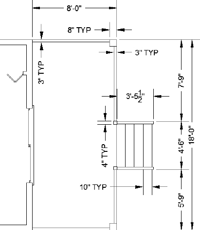
Figure 5.11 shows the dimensions of the front deck you'll draw.
- Make sure I05-02-BackThreshold.dwg (M05-02-BackThreshold.dwg) is open.
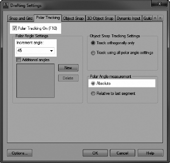
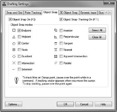
 Right-click the Polar Tracking button on the status bar at the bottom of the screen, and then choose Settings from the context menu. The Drafting Settings dialog box opens. By default, the Polar Tracking tab is active (see Figure 5.12).
- Before using Polar Tracking, you need to change a few settings:
- Starting in the upper-left corner, click the Polar Tracking On check box.
This has the same effect as clicking the Polar Tracking button in the status bar or pressing F10 from the Application window.
- In the Polar Angle Settings area, change the Increment Angle to 45.00.
- In the Polar Angle Measurement area found on the right side, make sure that Absolute is selected and then click OK to exit the Drafting Settings dialog box.
FIGURE 5.11 The dimensions of the front deck and stairs
FIGURE 5.12 The Polar Tracking tab of the Drafting Settings dialog box
The Polar Tracking button is turned on in the status bar, and the Ortho mode is automatically turned off. Polar Tracking is similar to Ortho mode, but it provides more angular increments to which you can snap the cursor.
- Starting in the upper-left corner, click the Polar Tracking On check box.
- Turn off the Object Snap Tracking button in the status bar.
The object snaps are also available from the Object Snap toolbar you loaded and saved within the AutoCAD NER workspace in Chapter 1, “Getting to Know Autodesk® AutoCAD®.” Some users prefer using the toolbar over other methods because the nonrunning osnaps can remain visible on the screen without the need to open a menu and, if necessary, the toolbars can be docked to the perimeter of the drawing area or moved to a second monitor.
Load the Object Snap toolbar from View Ribbon tab
 User Interface panel Toolbars tool; click AutoCAD Object Snap.
 - Start the Polyline (PLINE) command, and draw a polyline from the lower-right corner of the cabin to a point 8′-0″ (2438 mm) to the right.
 Click the Snap To Perpendicular button on the Object Snap toolbar. Place the cursor over the top-outside horizontal line of the cabin and, when the Snap marker appears (see Figure 5.13), click to draw the vertical line of the deck's perimeter.
FIGURE 5.13 Drawing the vertical line perpendicular to the upper cabin wall
- Click the top-right corner of the cabin to complete the perimeter of the deck, and then press to end the Polyline (PLINE) command.
Your drawing should look like Figure 5.14.
FIGURE 5.14 The perimeter of the front deck
- Offset the perimeter 3″ (72 mm) to the inside to represent the inside and outside edges of the handrail, and then terminate the OFFSET command.
- Save your drawing as I05-03-FrontDeck.dwg (M05-03-FrontDeck.dwg).
Drawing the Deck Posts
There are four posts on the deck: two 8″ (204 mm) posts at the corners that hold up the roof, and two 4″ (102 mm) posts at the top of the stairs. You will use the Rectangle (RECTANG) command to draw the posts and the MIRROR command to copy them:
- Make sure I05-03-FrontDeck.dwg (M05-03-FrontDeck.dwg) is open.
 Use the Rectangle (RECTANG) command, found on the Home tab Draw panel Rectangle tool, to draw a post 8″×8″ at the lower-right corner of the desk.
To do this, start the Rectangle (RECTANG) command. At the Specify first corner point or: prompt, click the endpoints where the lines form the lower-right corner of the deck. At the Specify other corner point or: prompt, enter -8,8
(-204,204) to draw the first 8″ (204 mm) post.The rectangle should be similar to Figure 5.15.
FIGURE 5.15 The first corner post
TIP You can start an AutoCAD command and then select objects, or you can select the objects first and then start the command. To create the opposite post, select the rectangle that you just drew and then start the MIRROR command (Home tab Modify panel Mirror tool).
 At the Specify first point of mirror line: prompt, click the Snap To Midpoint button on the Object Snap toolbar. Then pause the cursor over either of the vertical handrail lines.
When a feature is symmetrical like the deck, you can use the Midpoint snap to mirror objects about the centerline.
- Move the cursor directly to the left or right, as shown in Figure 5.16, to mirror the post. Then do the following:
- Use the TRIM command to trim the short polyline segments that fall within the posts.
When you are finished, each segment should look similar to Figure 5.17.
- Save your drawing as I05-04-DeckPosts.dwg (M05-04-DeckPosts.dwg).
The 4″ (102 mm) posts at the top of the stairs are centered on the 3″ (72 mm) handrails on the deck and on the stairs. To create the lower small post, you need to locate the bottom-right corner at a point ![]() (15 mm) to the right of the front handrail and
(15 mm) to the right of the front handrail and ![]() (1740 mm) from the bottom-right corner of the deck. Follow these steps:
(1740 mm) from the bottom-right corner of the deck. Follow these steps:
- Make sure I05-04-DeckPosts.dwg (M05-04-DeckPosts.dwg) is open.

Select the large lower post and start the COPY command from the Home tab
Modify panel on the Ribbon.- Select the lower-right corner point as the base point and then, at the Specify second point or: prompt, enter .5,5′8.5″ (15,1740).
- Press to end the COPY command. The copied post appears as shown in Figure 5.18.
- Zoom in to the new post. The bottom-right corner of the post is located in the correct location, but the post is twice the size that it should be.
 Start the SCALE command by clicking the Scale button from the Home tab Modify panel; then select the new rectangle.
- With the SCALE command active, select the lower-right corner as the base point. Then move the cursor to see the effect when the scale is based from that corner. A copy of the selected object appears, as shown in Figure 5.19.
- Enter 0.5 to scale the rectangle to 50 percent of its current size.
- Save your drawing as I05-05-StairPosts.dwg (M05-05-StairPosts.dwg).
FIGURE 5.18 The copied deck post
FIGURE 5.19 A copy of the scaled object appears as you move the cursor.
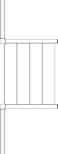
Drawing the Stairs
You could mirror the 4″ (102 mm) rectangle now to create the reciprocal post, but we'll wait until the stair handrails are complete and then mirror both objects at once. The first stair handrail is 3″ (76 mm) wide and centered on the 4″ (102 mm) post, so you'll use a temporary tracking point to locate the first point of the line.
- Make sure I05-05-StairPosts.dwg (M05-05-StairPosts.dwg) is open.
 Start the LINE command, and click the Temporary Track Point button in the Object Snap toolbar, or enter TT at the command line.
- Using the running Endpoint osnap, click the lower-right corner of the small post to locate the temporary tracking point.
- With the temporary tracking point located, move the cursor directly upward and enter .5 (13) to place the start point
 (13 mm) above the corner.
 - To complete the handrail, do the following:
- Move the cursor directly to the right, and enter 3′5.5 (1054).
- Move the cursor directly upward, and enter 3 (72).
- Move the cursor directly to the left, and enter 3′5.5 (1054).
Instead of entering the exact distance of the final line, you could also use the Perpendicular object snap to complete the handrail.
Your first handrail should look like Figure 5.20.
- Move the cursor directly to the right, and enter 3′5.5
- Save your drawing as I05-06-DrawStairRail.dwg (M05-06-DrawStairRail.dwg).
Mirroring the Post and Railing
You can now mirror the post and railing to draw them on the opposite side of the stairway. You can't use the midpoint of the deck's perimeter line as one point of the mirror line, because the stair is centered on the front door and not on the deck. You can, however, use the midpoint of the front door's threshold.
- Make sure I05-06-DrawStairRail.dwg (M05-06-DrawStairRai1.dwg) is open.
- Select the 4″ (102 mm) post and all three lines that make up the handrail. Try using a window selection (drag from left to right) to select the objects rather than picking them one at a time.
FIGURE 5.20 The first handrail
- Start the MIRROR command.
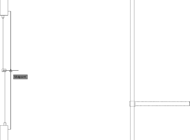
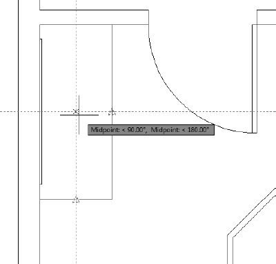
- Use the Midpoint osnap, and then specify the midpoint of the vertical threshold line as the first point of the mirror line, as shown in Figure 5.21.
- Move the cursor to the right, and then click to specify the second point of the mirror line. Press to retain the source objects.
Your deck should look like Figure 5.22.
- Zoom in until you can see both stair handrails and posts.
- Break the outside perimeter line of the deck into individual line entities by using the EXPLODE command.
FIGURE 5.21 Using the midpoint of the threshold as the first mirror point
FIGURE 5.22 The deck with both handrails
- Start the COPY command from the Home tab Modify panel. Select the outside perimeter line of the deck to begin building the stairs.
- Pick any point near the stairs at the Specify base point: prompt.
- Enable the Array option of the COPY command by entering A at the Specify second point: prompt.
- Use the following values to complete the array:
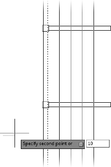
- Enter 5 at the Enter number of items to array: prompt.
- Move your cursor directly to the right, and enter 10 (254) at the Specify second point or: prompt (see Figure 5.23).
FIGURE 5.23 Using the Array function of the COPY command to create stairs for the deck
- Enter 5
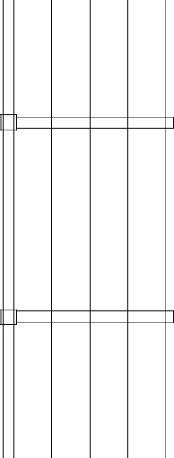
- Assuming the preview looks like Figure 5.24, press to accept the array. The COPY command ends, and your stairs are drawn.
Now you will use the TRIM command to trim away the stair lines that extend into and beyond the railings and the lines that pass through the 4″ (102 mm) posts.
- Start the TRIM command. Select both of the inside lines of the stairway handrails and the 4″ (102 mm) post polylines as the cutting-edge objects.
FIGURE 5.24 The stairs created using the COPY command
TIP Make sure that you do not select the offset perimeter polylines as cutting edges. When polylines are selected as cutting edges and then as the trimmed objects, they are trimmed back to the endpoint nearest to the picked location. - Trim the four stair lines on both sides of the railing.
- Of the two vertical lines that extend between the two posts, trim only the left vertical line.
- Trim away the four short lines that pass through the two 4″ (102 mm) posts, and erase the additional line along the inside perimeter.
When complete, your front stairway should look like Figure 5.25.
- Zoom to the drawing's extents.
- Save your drawing as I05-07-FrontStairs.dwg (M05-07-FrontStairs.dwg).
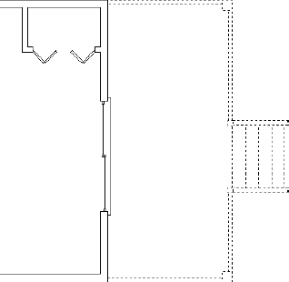
Drawing the Back Deck and Stairs
The deck, handrails, posts, and stairs at the rear portion of the cabin are similar to the same features at the front of the cabin. One of the most significant strengths of CAD software over traditional hand drafting is the ability to use existing geometry and linework in a drawing to create additional identical or similar objects. In this section, you will first mirror the front deck to the back of the cabin. I will then introduce you to the STRETCH command to adjust the lines to match the cabin's structure. Figure 5.26 shows the dimensions of the rear deck that are different from those on the front deck.
Mirroring the Front Deck
Several similarities exist between the front and back decks of the cabin. Using these similarities to your advantage, the following steps utilize this existing geometry by mirroring the front deck to the back of the cabin:
- Make sure I05-07-FrontStairs.dwg(M05-07-FrontStairs.dwg) is open.
- Verify that the following drawing modes are active:
- Polar Tracking
- Object Snap
- Dynamic Input
FIGURE 5.26 The dimensions of the rear deck and stairs
- Start the MIRROR command.
- Use a crossing selection window to select all the components of the front deck, but do not select the cabin wall, front door, or threshold.
If you inadvertently select an unwanted object, hold down the Shift key and pick the object again to deselect it. The dashed, selected set should look like Figure 5.27.
- At the Specify first point of mirror line: prompt, activate the Midpoint osnap and click near the midpoint of the top, outside wall line.
As discussed earlier, as long as the Midpoint snap marker displays at the correct midpoint, it is not necessary to pick the exact midpoint of the line.
- Move the cursor downward. With Polar Tracking active, the cursor is restricted to the 270° angle, causing the deck to be mirrored perfectly to the rear of the cabin, as shown in Figure 5.28.
FIGURE 5.28 Mirroring the front deck to the rear of the cabin
- Click to define the mirror line, and press to retain the source objects. The front deck is mirrored to the back of the cabin.
- Save your drawing as I05-08-MirrorDeck.dwg (M05-08-MirrorDeck.dwg).
Using the Stretch Command to Size the Deck
The STRETCH command is used to lengthen or shorten objects in the drawing area. The major restriction when using it is that the objects must be selected with a crossing window or crossing polygon, so be sure to define your selection window from right to left or to enter CR![]() at the Select objects: prompt.
at the Select objects: prompt.
When part of an object resides inside the crossing window borders, the portion inside the window is moved, the portion crossing the border is stretched, and the portion outside the border is unaffected. When an object is completely inside the crossing window, it is affected as if the MOVE command were used.
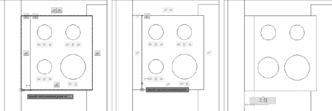
Figure 5.29 shows the result when the top portion of the objects in a drawing are selected and stretched. The far-left image shows a crossing selection window encompassing the entire top portion of the objects, and the middle-left image shows the result of stretching the objects upward. The middle-right image shows a crossing selection window encompassing only the right half of the top portion of the objects, and the far-right image shows the result of stretching the objects upward. Some objects, such as circles, ellipses, and blocks, cannot be stretched.
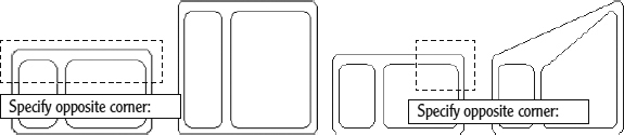
FIGURE 5.29 Selecting and stretching the entire top portion (left) and only the top-right portion (right)
Complete the following steps to fix the rear deck and stairs by using the STRETCH command:
- Make sure I05-08-MirrorDeck.dwg (M05-08-MirrorDeck.dwg) is open.
- Zoom in to the rear deck and stairs.
 Start the STRETCH command from the Home tab Modify panel Stretch tool, or enter S at the command line.
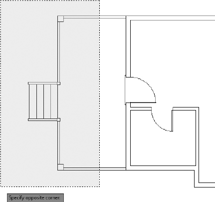
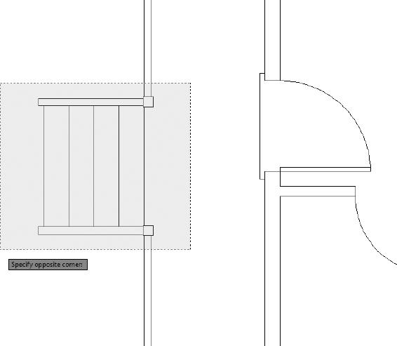
- At the Select objects: prompt, place the cursor above the deck and to the right of the stairs, but be sure the point is to the left of the threshold (see Figure 5.30).
- At the Specify opposite corner: prompt, click a point outside and to the left of the deck, as shown in Figure 5.30. The deck objects ghost to indicate that they are selected. Press to discontinue selecting objects.
FIGURE 5.30 Selecting the deck components for the STRETCH command
Like the MOVE command, STRETCH requires you to specify a base point and a second point to define the result of the stretch. The selected objects are stretched to the same distance and angle as the relationship between those two points. For example, after selecting objects to stretch on the right side of the drawing area, you can select a base point on the left side of the drawing area and a second point 2″ above the base point. The selected objects on the left are stretched upward 2″.
You can reference objects or features in the drawing area or select a random point for the base and specify the angle and distance for the second point.
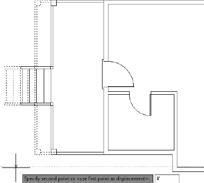
- The open end of the deck needs to be stretched 4′-0″ (1220 mm) to the right. Pick a point anywhere in the drawing area and then move the cursor to the right. You will see the deck stretching to the right, while a ghosted version remains in place (see Figure 5.31).
FIGURE 5.31 The deck after specifying the base point for the STRETCH command
- Enter 4 (1220). The deck is stretched 4′-0″ (1220 mm) to the right.
- Save your drawing as I05-09-StretchDeck.dwg (M05-09-StretchDeck.dwg).
Using Point Filters to Finish the Deck
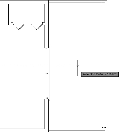
To complete the back deck, you need to align the center of the stair with the center of the door. To do this, we'll combine what you already know about object snaps with the STRETCH command and a feature named point filters. Point filters, also called coordinate filters, are tools you can utilize to use only the X, Y, or Z value of a selected point in the drawing area.
For example, suppose you want to stretch an object to the center of a rectangle but you don't know where that center is located. You could draw a bunch of construction lines, only to erase them in a few minutes, or you could forgo all of that with point filters. In this scenario, you would use the X point filter and pick the midpoint of a horizontal line from the rectangle; then you'd use the Y point filter and pick the midpoint of a vertical line from the rectangle.
The resulting location is at the intersection of the midpoint of the two sides of the rectangle at the center point. More important, you didn't spend any unnecessary time drawing and then erasing construction lines. Let's take a look at how you can employ this same method to finish the back deck. Follow these steps:
- Make sure I05-09-StretchDeck.dwg (M05-09-StretchDeck.dwg) is open.
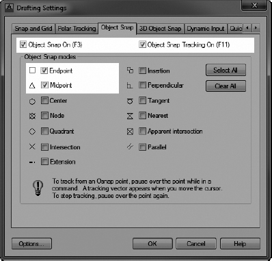
- Verify that Polar Tracking, Object Snap, and Dynamic Input are still enabled, and then turn on the Midpoint and Endpoint object snaps from the Drafting Settings dialog box, as shown in Figure 5.32.
FIGURE 5.32 Enabling the Endpoint and Midpoint object snaps from the Drafting Settings dialog box
- Create a crossing selection window around the stairs, stair handrails, and stair posts, as shown in Figure 5.33.
- At the Specify base point or: prompt, use the Midpoint osnap and pick the midpoint of the top step.
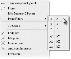
- At the Specify second point or: prompt, hold the Shift key down and right-click to open the Osnap context menu. Choose Point Filters .X (see Figure 5.34).
This allows you to pick a point that is horizontally (X) equal to the same location as the point you selected in step 4 and vertically (Y) equal to the midpoint of the threshold.
FIGURE 5.33 Select the stairs for the next STRETCH command.
FIGURE 5.34 Select the .X point filter from the Object Snap context menu.
The prompt in the command-line interface has .X appended to indicate that AutoCAD will use only the X component of the next location picked.
- Click either endpoint of the top step. This point is in line with the midpoint you picked in step 4, so the stretch will move the stairs vertically, not horizontally.
Move the cursor around in the drawing area, and you'll see that the movement of the stairs is now restricted to the y-axis. In the command-line interface, the notation (need YZ) is appended to the prompt, indicating that AutoCAD will use only the Y and Z components of the next location picked. (Only the y-axis is referenced if you are using AutoCAD LT®.)
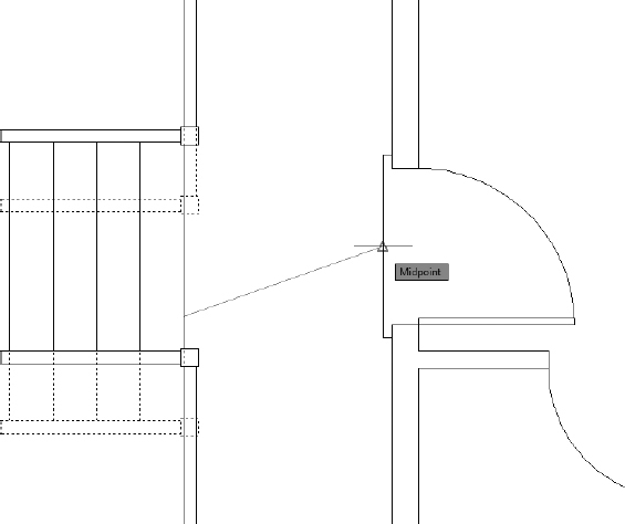
- Click the Snap To Midpoint button in the Object Snap toolbar, and then click the midpoint of the threshold (see Figure 5.35).
FIGURE 5.35 Select the midpoint of the threshold as the Y and Z components of the second point.
- The stairs are moved vertically and centered on the back door. Zoom to the drawing's extents. Your drawing should look like Figure 5.36.
- Save your file as I05-10-PointFilter.dwg (M05-10-PointFilter.dWg).
Laying Out the Kitchen
The kitchen for the cabin will have a stove, a refrigerator, and a counter with a sink. The refrigerator is set 2″ (51 mm) from the back wall. Approaching this drawing task, your goal is to think about the easiest and fastest way to complete it. The first step in deciding on an efficient approach is to ascertain what information you have about the various parts and what existing elements in the drawing will be available to assist you. Figure 5.37 gives you the basic dimensions, and you'll get more-detailed information about the sink and stove as you progress through the exercise.
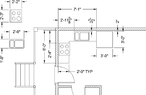
FIGURE 5.37 The general layout of the kitchen
Drawing the Counter
Although the counter is in two pieces, you'll draw it as one piece and then cut out a section for the stove. Try two ways to draw the counter to see which method is more efficient.
Method 1: Using Object Snap Tracking and Direct Entry
The first drawing method uses Object Snap Tracking and direct entry:
- Continue with the drawing from the previous exercise or open I05-10-PointFilter.dwg (M05-10-PointFilter.dwg)from the book's web page.
- Use a zoom window to zoom your view so that it is about the same magnification as Figure 5.38.
FIGURE 5.38 Zoom in to the kitchen area.
- From the status bar, turn on Object Snap Tracking. Verify that Polar Tracking, Object Snap, and Dynamic Input are still on. The rest of the buttons should be off.
- Start the LINE command to begin drawing the counter.
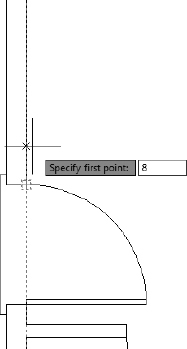
- Place the cursor near the lower end of the right-rear doorjamb line, where the door swing meets the wall. A small cross is superimposed over the Endpoint osnap icon, indicating the reference location for Object Snap Tracking.
- Move the cursor upward. Then enter 8 (204) to start the counter line 8″ (204mm) from the corner of the jamb (see Figure 5.39).
FIGURE 5.39 Setting the location for the first counter line
- Hold the crosshair cursor directly to the right of the first point of the line, and enter 2′ (610).
- Hold the crosshair cursor upward, and enter 4′ (1220).
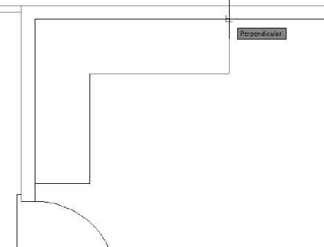
At this point, you have drawn two line segments defining the counter on the back wall of the cabin. You can see the dimensions in Figure 5.37, shown earlier.
- Hold the cursor to the right again, and enter 5′1″ (1550) to draw the long counter line that runs in front of the sink.
- Select the Perpendicular osnap, and then pick the inside wall line, as shown in Figure 5.40, to complete the counter.
- Press to end the LINE command.
Method 2: Using Offset and Fillet
As with launching commands, most tasks in AutoCAD give you options galore for completing them. Although some methods are viewed as being more efficient than others, the “best” method is often a matter of personal preference. In this exercise, you're going to draw the same counter you drew in the previous exercise, except this time you will use the OFFSET and FILLET commands.
To complete this exercise, you'll need to erase the countertop you just drew. You could use the ERASE command to do this, but because all four of the line segments were drawn in one cycle of the LINE command, you can also use the UNDO command.
 Click the Undo button on the Quick Access toolbar, enter U at the command line, or use the standard Windows keyboard shortcut Ctrl+Z.
Alternatively, you can open I05-10-PointFilter.dwg (M05-10-PointFilter.dwg) from the book's web page.
The counter you just drew should disappear. If you ended the LINE command while drawing the counter and had to restart it before you finished, you might have to click the Undo button more than once.
 If you undo too much, click the Redo button, which is just to the right of Undo.
Now you'll draw the counter again, this time using the OFFSET and FILLET commands.
- Offset both the left-inside wall line and the top-inside wall line 2′ (610 mm) to the inside of the cabin.
- Stop and then restart the OFFSET command. This time, offset the inside left wall line 7′-1″ (2159 mm) to the right.
- Next, offset the inside top wall line 6′-0″ (1829 mm) downward—the sum of the two counter dimensions and the stove dimension (see Figure 5.41).
FIGURE 5.41 Offsetting wall lines to create the counter
TIP As discussed earlier, if the FILLET command has a nonzero radius setting that you want to keep, hold down the Shift key to set the radius to zero for one use of the command. After the command ends, the radius returns to its nonzero setting. - Use the FILLET command with a radius of zero to clean up the three corners. Be sure to click the portions of the lines that you want to retain.
- Save your file as I05-11-KitchenCounter.dwg (M05-11-KitchenCounter.dwg).
Now that you have tried both ways, you can decide which of the two methods is more practical for you. Both are powerful techniques for laying out orthogonal patterns of lines for walls, counters, and other objects.
UNDOING AND REDOING IN AUTOCAD
AutoCAD has various Undo options, and they operate quite differently:
- When you click the Undo button on the Quick Access toolbar, you're using the AutoCAD U command. You can also start it by entering U. The U command works like the Undo command for Windows-compliant applications by undoing the results of the previous commands one step at a time. Using the Ctrl+Z hot-key combination also executes the U command.
- The UNDO command in AutoCAD has many options, and you start it by entering UNDO. You use this approach when you want to undo everything you've done since you last saved your drawing or to undo back to a point in your drawing session that you specified earlier by using the Mark option. Be careful when you use the UNDO command; you can easily lose a lot of your work.
- The OOPS command is a special Undo tool that restores the last objects erased, even if the ERASE command wasn't the last command executed.
- The REDO command will undo the effect of several undo operations. So, if you undo a few steps too many, you can still get them back. The Redo tool must be used immediately after using the Undo tool.
- Both the Undo and Redo buttons on the Quick Access toolbar have small down-arrows to their right. Clicking these arrows displays a drop-down menu showing a list of the recent commands used (Undo) or undone (Redo). When there are several commands to be undone or redone, selecting the command to be undone may be faster than clicking the Undo or Redo button repeatedly.
Drawing the Stove and Refrigerator
The stove and refrigerator are simple rectangles. Here you will use the Temporary Tracking Point osnap to locate the first corner of each shape:
- Make sure I05-11-KitchenCounter.dwg (M05-11-KitchenCounter.dwg) is open.
- To begin drawing the refrigerator, click the Rectangle button on the Home tab Draw panel, or enter REC at the command line.
- Verify that Object Snap, Object Snap Tracking, and Dynamic Input are still enabled on the status bar.
- Place your cursor near the upper end of the right side of the counter, letting the running Endpoint osnap establish an object snap tracking point.
- Move your cursor down, and enter 2 (51), as shown in Figure 5.42.
FIGURE 5.42 Locating the first corner of the rectangle
This starts the rectangle 2″ (51 mm) from the back wall, along the side of the counter.
- To specify the opposite corner of the rectangle, enter 36,-36 914,-914.
The Rectangle (RECTANG) command ends, and the refrigerator is drawn at the end of the counter that is running along the back wall. Next you'll use a similar process to draw a basic outline of the stove.
- Right-click and choose Repeat RECTANG from the context menu that opens.
- Use the technique from step 4, but pick the lower end of the left side of the counter as the tracking point.
- Hold the cursor directly above that point, and enter 1′5″ or 17 (432). Then enter 26,27 (660,686) to complete the rectangle.
- Use the TRIM command to trim away the front edge of the counter that passes through the stove.
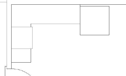
Your kitchen should look like Figure 5.43.
- Save your file as I05-12-Refrigerator.dwg (M05-12-Refrigerator.dwg).
 NOTE Because the stove rectangle is drawn as a polyline, you need to select only one segment of it for all sides of the rectangle to be selected and, in this case, for them to become cutting edges.
Completing the Stove with Parametrics
![]()
At this point, the cabin is really starting to take shape with the numerous lines, arcs, and polylines that you have drawn. There is, however, a significant disconnect between what you see and what AutoCAD sees while viewing the cabin. To you, it's a cabin; you see how the stairs are spaced equally, how the wall intersections form perpendicular angles, and in general how objects relate to other objects within your drawing.
AutoCAD, on the other hand, sees nothing more than a collection of lines, arcs, and polylines. It doesn't know that walls should form 90° angles where they intersect or that the two lines representing door openings should be parallel and spaced a certain distance apart. Currently, every object inside your drawing is independent from the other objects in your drawing.
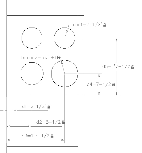
Parametric drawing offers a solution to this disconnect; it allows you to assign both geometric and dimensional constraints to the objects inside your drawing. Whereas dimensional constraints must be applied manually, geometric constraints may be applied manually, automatically, or inferred while drawing. Using the dimensions shown in Figure 5.44, you'll have the chance to explore each of these methods as you use parametrics to complete the stove.
AUTOCAD LT USERS
The AutoCAD LT Ribbon does not include tools for creating geometric or dimensional constraints because parametric drawing is one of the features found only in the full version of AutoCAD. Because AutoCAD LT users will not be able to complete the next several exercises on parametric drawing, please substitute the following exercise to complete the stove:
- Make sure I05-12-Refrigerator.dwg (M05-12-Refrigerator.dwg) is open.
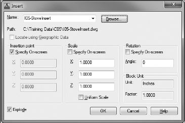
- Start the INSERT command by using the Insert button found on the Insert tab Block panel. The Insert dialog box appears.
- Click the Browse button to browse to the file I05-StoveInsert.dwg (M05-StoveInsert.dwg) found inside the Chapter 5 data directory.
If you haven't done so already, you can download this file from this book's web page at www.sybex.com/go/autocad2013ner or www.theacadgeek.com.
- You are taken back to the Insert dialog box. Before clicking OK, select the Specify On-Screen check box under Insertion Point, and the Explode check box in the lower-left corner.
These should be the only two check boxes selected inside the Insert dialog box, as shown in the following illustration.
- Use the Endpoint osnap to select the lower-back corner of the stove.
The stove is completed as the remaining geometry is inserted into the drawing.
- Save your file as I05-16-CompleteStove.dwg (M05-16-CompleteStove.dwg).
Proceed to the “Drawing the Kitchen Sink” exercise later in this chapter.
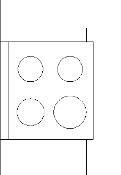
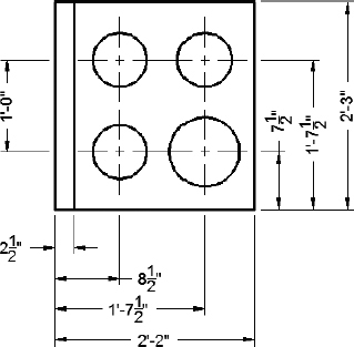
FIGURE 5.44 The details of the stove
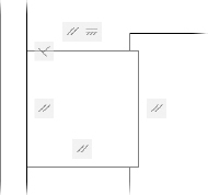
Getting Started with Geometric Constraints
![]()
The first step in using parametric drawing is to define how objects should interact geometrically. This is done by assigning geometric constraints to your model. These constraints will reinforce the use of tools such as object snaps to define the intersection of two lines as coincident, or two lines forming a right angle as perpendicular. Because you're not yet dealing with size, the primary focus in this exercise is to ensure that objects that should intersect do so, objects that should form right angles are indeed perpendicular, and parallel lines are truly parallel.
Assuming you were diligent in creating your linework, the Auto Constrain tool will automatically determine and assign the necessary geometric constraints. Follow these steps to autoconstrain your stove:
- Make sure I05-12-Refrigerator.dwg (M05-12-Refrigerator.dwg) is open, and zoom in to a closer view of the stove.
 Select the current outline of the stove, and click the Auto Constrain tool, which is found on the Parametric tab Geometric panel.
After you invoke Auto Constrain, a series of icons appear along the perimeter of the stove, as shown in Figure 5.45. These icons illustrate the geometric relationships AutoCAD established between the four lines that define the outline of your stove.
FIGURE 5.45 Geometric constraints applied by using the Auto Constrain tool
If no icons appear after you invoke Auto Constrain, use the Show All tool found on the Parametric tab
Geometric panel.The positioning of these icons may be slightly different than shown in Figure 5.45; it's more important to verify that you have the same geometric constraints as shown.
- Hover the cursor over the Geometric Constraint icons that are shown around the perimeter of the stove.
The geometric relationship displays as you hover over each Geometric Constraint icon. For instance, the parallel geometric constraint highlights both the adjacent Geometric Constraint icon and the line to which the two lines are parallel. This inquiry method is an especially helpful way of visualizing which objects relate to other objects inside your drawing.
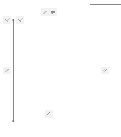
 Turn on Infer Constraints from the status bar. In addition, Object Snap, Object Snap Tracking, and Dynamic Input should still be on.
- Use the LINE command and the Nearest and Perpendicular object snaps to draw a vertical line, as shown in Figure 5.46.
FIGURE 5.46 Geometric constraints inferred after drawing a line
- Save your file as I05-13-AutoConstrain.dwg (M05-13-AutoConstrain.dwg).
Don't worry about being terribly accurate at this point. You'll apply dimensional constraints in a moment. Right now you're interested in only the geometric relationships between objects.
Drawing the Stove Burners
![]()
The next step is to draw the circles that represent the burners. As with the last exercise, we're not overly concerned about size at this point. Instead, the focus is on getting the geometry correct first, and then you'll come back to further constrain the stove with dimensional constraints.
- Make sure I05-13-AutoConstrain.dwg (M05-13-AutoConstrain.dwg) is open.
 Click the down-arrow next to the Circle tool, found on the Home tab Draw panel, and look at the fly-out menu, as shown in Figure 5.47.
FIGURE 5.47 The Circle command's fly-out menu
You have six options for constructing a circle:
- The first two (Center, Radius; and Center, Diameter) require you to specify a point as the center of the circle and to enter a radius or a diameter.
- You use the next two (2-Point and 3-Point) when you know two or three points that the circle must intersect.
- The last two options (Tan, Tan, Radius; and Tan, Tan, Tan) use tangents and a radius, or just tangents, respectively, to form a circle.
Notice that each circle construction method has a unique icon on the left side of the fly-out menu. Whichever method was used last becomes the default method when you click the Circle button, and its icon appears on the button.
- Choose the Center, Radius option from the fly-out menu.
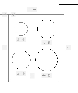
- The command prompt changes from Specify center point for circle or: to Base point:. Draw four circles as shown in Figure 5.48.
- Save your file as I05-14-StoveBurners.dwg (M05-14-StoveBurners.dwg).
Once again, your intent at this point is to develop a solid geometric representation of the stove. Before applying dimensional constraints, I'll show you how to add some additional geometric constraints.
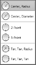
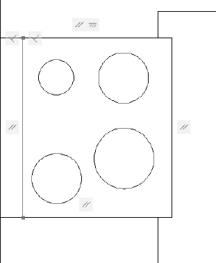
FIGURE 5.48 Rough schematic representation of the stove
Applying Additional Geometric Constraints
![]()
You've seen how the Auto Constrain and Infer Constraints features make it easy to add geometric constraints to your drawing. Although both are incredibly powerful features, sometimes you need an extra degree of control over how geometric constraints are added to your drawing. For this reason, you have the option of manually adding geometric constraints to objects inside your drawing.
Even if you had been more deliberate in drawing the burners with the proper alignment and size, the Auto Constrain feature would still have a difficult time establishing how the four burners truly interact with one another. Consequently, to ensure that the constraints are correctly applied, the best approach in this case is to define the necessary geometric constraints manually. To do this, you'll use many of the individual constraint icons found on the Parametric tab ![]() Geometric panel.
Geometric panel.
- Make sure I05-14-StoveBurners.dwg (M05-14-StoveBurners.dwg) is open.
- Confirm that Infer Constraints, Object Snap, Object Snap Tracking, and Dynamic Input are still enabled on the status bar.
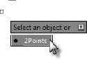
 Click the Horizontal constraint tool from the Parametric tab Geometric panel.
- From the Select an object or [2Points]: prompt, press the down-arrow to select 2Points, as shown in Figure 5.49.
FIGURE 5.49 Selecting the 2Point option when using Dynamic Input
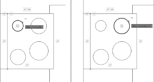
- Hover over the top-left burner, and select it when a small red circle with an X appears in the center, as shown on the left in Figure 5.50.
FIGURE 5.50 Using the Horizontal constraint to select the center point of the circle
- From the Select second point: prompt, use the same method to select the center point of the top-right burner, as shown on the right in Figure 5.50.
The two right burners (as if you were working at the stove and facing the rear deck) are now constrained horizontally; this means that, although the two burners may be located anywhere along the y-axis, they will always be aligned along the x-axis. You can try this out by using the MOVE command to move either one of the burners. Notice how the second burner also moves even though it was not selected.
- Use the Horizontal constraint once again, repeating steps 5 and 6 to constrain the two burners on the left side of the stove.
All of the burners are now constrained horizontally; however, there is no relationship between the left and right burners. To fix this, you will continue constraining the burners, this time applying Vertical constraints between the right and left burners.
 Click the Vertical constraint tool from the Parametric tab Geometric panel.
- At the Select an object or [2Points]: prompt, click the down-arrow to select 2Points using Dynamic Input.
- Use the Vertical 2Point constraint tool to select the center points of the two front burners.
- Repeat the Vertical constraint tool once again, this time selecting the center points of the two rear burners.
Each of the burners is now fully constrained horizontally and vertically. Notice how moving a single burner also moves the two adjacent burners. Note the Constraint icons under each of the burners; your stove should look like Figure 5.51.
Because three of the burners are the same size, you can use the Equal geometric constraint to build a relationship between the two right burners and the back-left burner. It's important to remember that the focus here is to get the geometry correct. You'll apply dimensional constraints shortly to size each of the burners correctly.
 Click the Equal constraint tool from the Parametric tab Geometric panel.
- Select the back-right burner and then the front-right burner to set the radius of each equal to the back-right burner.
FIGURE 5.51 Burners fully constrained horizontally and vertically
- Repeat the process once again, this time selecting the back-right burner and the back-left burner.
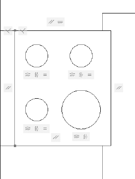
Your stove should look like Figure 5.52.
- Save your file as I05-15-GeometricConstraints.dwg (M05-15-GeometricConstraints.dwg).
FIGURE 5.52 Stove with Equal constraints applied to three burners
Applying Dimensional Constraints
![]()
The previous several exercises gave you the opportunity to focus on geometry, not dimensions. Although the stove is geometrically correct, it's currently drawn with a series of arbitrary dimensions. Dimensional constraints let you assign real values to the geometry in your drawing. Thanks to the geometric constraints you have already applied to the stove, you'll need to apply dimensional constraints to only a few key points. The geometric constraints will handle the rest for you automatically, ensuring that the integrity of the relationships is retained.
Dimensional constraints function similarly to regular dimensions in AutoCAD. You'll have the chance to take a closer look at dimensions in Chapter 12, “Dimensioning a Drawing,” but your experience with parametrics will certainly provide a great foundation from which to build. One core difference between regular dimensions and parametric dimensions is that parametric dimensions require you to select both an object and a point. In contrast, regular dimensions require you to specify only a point. You'll use the dimensions shown earlier in Figure 5.44 to apply the necessary dimensional constraints.
- Make sure I05-15-GeometricConstraints.dwg (M05-15-GeometricConstraints.dwg) is open.
- Add a Linear dimensional constraint to the stove's rear control panel as follows:
 Choose the Linear dimensional constraint from the Parametric tab Dimensional panel.
- Hover over the bottom-right corner of the stove, and then click to accept the endpoint.
- Hover over the lower endpoint for the line representing the stove's control panel, and click to accept the point.
- Specify a location for the dimensional constraint, and then enter 2.5″ (64 mm) as the value for d1 (see Figure 5.53).
FIGURE 5.53 Applying a Linear dimensional constraint to the stove's control panel
- Using the Linear tool found on the Parametric tab Dimensional panel once again, add an
 (216 mm) constraint between the back-lower corner and the center point of the left-rear burner.
 - Continue using the Linear tool to add the following dimensional constraints:
- Add a
 (495mm) constraint between the back-lower corner and the center point of the left-front burner.
 - Add a
 (190mm) constraint between the lower-front corner of the stove and the left-front burner.
 - Add a (495mm) constraint between the lower-front corner of the stove and the right-front burner.
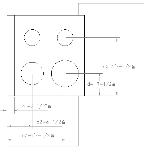
Figure 5.54 shows the result. You have created a total of five Linear constraints. These constraints have correctly positioned the rear control panel and each of the four burners for the stove. The only thing left to do is correctly size each of the four burners.
Because you used the Equal geometric constraint on three of the burners, properly sizing the burners will require only two Radius constraints.
FIGURE 5.54 Linear constraints applied to the stove
- Add a
 Choose the Radius tool from the Parametric tab Dimensional panel.
- From the Select arc or circle: prompt, select the front-right burner and choose a position for the dimensional constraint.
- Enter a value of
 (89 mm) for the rad1 constraint.
The Equal geometric constraint updates the radius of the back-right and back-left burners to match the
(89 mm) radius you specified for the front-right burner. - Repeat steps 5 through 7 to apply a Radius constraint on the front-left burner. When prompted for the radius, enter rad1+1 (rad1+25).
Figure 5.55 shows the result.
FIGURE 5.55 Fully constrained stove
Much like formulas can reference the value of other cells in Microsoft Excel, dimensional constraints can reference other dimensional constraints. In this example, you referenced a constraint applied to the front-right burner by entering its name (rad1). The expression rad1+1 is actually a mathematical expression telling AutoCAD to gather the value of rad1
 , and add 1″ to it for a total radius of
  (114 mm).
 - Save your file as I05-16-CompleteStove.dwg (M05-16-CompleteStove.dwg).
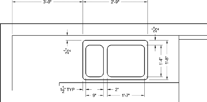
Drawing the Kitchen Sink
In this section, you'll draw a double sink with one basin larger than the other (see Figure 5.56). You'll use OFFSET, FILLET, and TRIM to create the sink from the counter and wall lines.
- Make sure I05-16-CompleteStove.dwg (M05-16-CompleteStove.dwg) is open. Zoom in to the sink area, keeping the edges of the refrigerator and stove in view.
FIGURE 5.56 The sink with dimensions
- Create the top and bottom edges by using the OFFSET command:
- Offset the inside wall line
 (64 mm) down.
 - Restart the OFFSET command, and offset the inside wall line 1′-8″ (508 mm).
This forms the top and bottom edges of the sink. Next, you will draw the left and right edges of the sink.
- Offset the inside wall line
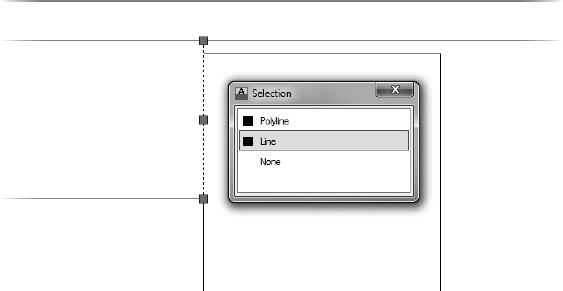
 From the status bar, turn on Selection Cycling.
- Restart the OFFSET command, and set the offset distance to 16″ (406mm).
You're going to offset the right side of the counter 1′-4″ (406 mm) to the left, but it coincides with the left side of the refrigerator. You'll use Selection Cycling to ensure that you select the correct line.
- At the Select object to offset: prompt, select the right edge of the counter. Because you enabled Selection Cycling in step 3 and both the right edge of the counter and left edge of the refrigerator coincide with one another, the Selection dialog box displays (see Figure 5.57).
- Select the Line option from the Selection dialog box, and complete the OFFSET command by picking a point to the left of the selected line. Notice how the object highlighted in the Selection dialog box also highlights (dashes) inside the drawing (see Figure 5.57).
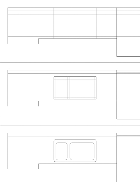
- Offset this new line 2′ 9″ (838mm) to the left. This forms the outside edge of the sink (see the top of Figure 5.58).
FIGURE 5.57 Using Selection Cycling to select the right edge of the counter
- Fillet the corners of this rectangle to clean them up, using a radius of zero.
- Perform the following offsets to draw the sink basins:
- Offset the left side, bottom, and right sides of the sink 1.5″ (38 mm) to the inside.
- Offset the top side 2.5″ (64 mm) to the inside.
- Offset the left basin edge to the right 9″ (229mm).
- Offset the right basin edge to the left 1′-7″ (483 mm). This forms the basis of the inside sink lines (see the middle of Figure 5.58).
FIGURE 5.58 The offset lines to form the outside edge of the sink (top), the offset lines to form the inside edges of the sink (middle), and the finished sink (bottom)
- Trim away the horizontal top and bottom inside sink lines between the two middle vertical sink lines.
- Fillet the four corners of each basin with a 2″ (51mm) radius to clean them up. Use the Multiple option of the FILLET command so that you won't need to restart the command continually.
- Fillet all four outside sink corners with a 1.5″ (38mm) radius. This finishes the sink (see the bottom of Figure 5.58). Use Zoom Previous to view the whole kitchen with the completed sink.
- Save your file as I05-17-KitchenSink.dwg (M05-17-KitchenSink.dwg).
This completes the kitchen area. You drew no new lines to complete this task because you created most of them by offsetting existing lines and then trimming or filleting them. Keep this in mind as you move on to the bathroom.
Constructing the Bathroom
The bathroom has three fixtures—a sink, a shower, and a toilet—as well as a mirror and a shelving unit. While you are drawing the bathroom, you'll draw the hot tub in the main room as well (see Figure 5.59). When drawing these fixtures, you'll use a few object snaps over and over again. You can set one or more of the osnap choices to run continually until you turn them off. That way, you won't have to select them each time.
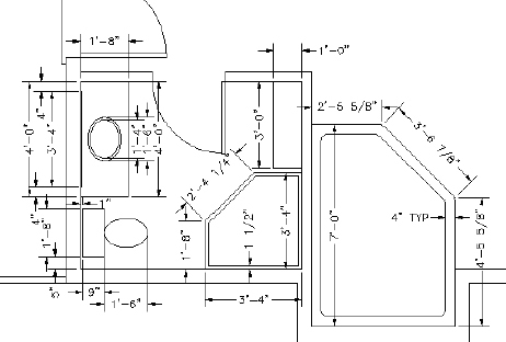
FIGURE 5.59 The bathroom fixtures and hot tub with dimensions
Setting Running Object Snaps
You'll set three osnaps to run continually for now, until you get used to how they work:
- Make sure I05-17-KitchenSink.dwg (M05-17-KitchenSink.dwg) is open.
- Right-click the Object Snap button on the status bar, and then choose Settings from the context menu to open the Drafting Settings dialog box.
By default, the Object Snap tab is current (see Figure 5.60).
FIGURE 5.60 The Object Snap tab of the Drafting Settings dialog box
Each of the 13 osnap options has a check box and a symbol next to it. The symbol appears as a marker in the drawing when you select a particular osnap, and the cursor is near a point where you can use that osnap. You can select any number of osnaps to be running at a time.
NOTE You can choose a different color for the markers if you want. If you're using a dark background in the drawing area, use a bright color, such as yellow. For a white background, try blue. To change colors, start the OPTIONS command and then choose the Colors button from the Drafting tab. - From the Object Snap tab of the Drafting Settings dialog box, click the check boxes next to Endpoint, Midpoint, and Intersection. Also ensure that the check box next to Object Snap On is selected in the upper-left corner of the dialog box.
- Click OK to close the dialog box.
The Endpoint, Midpoint, and Intersection osnaps will now be active anytime you're prompted to select a point on the drawing. You can deactivate them by turning off the Object Snap button in the status bar or by pressing F3.
Now you're ready to begin drawing the bathroom. The shower determines the placement of the other two items, so let's start there.
Drawing a Shower Unit
You'll start the shower unit with a rectangle and then trim away one corner. As you start this exercise, check the status bar. The Polar Tracking, Object Snap, Object Snap Tracking, and Dynamic Input buttons should be in their On positions. The rest of the buttons should be off. Follow these steps:
- Make sure I05-17-KitchenSink.dwg (M05-17-KitchenSink.dwg) is open.
- Verify that Polar Tracking, Object Snap, Object Snap Tracking, and Dynamic Input are turned on. The remaining drawing modes should be turned off.
- Enter Z E or click the Zoom Extents button to zoom to the drawing's extents. Then use the zoom window or the scroll wheel to view the bathroom close up.
- Start the Rectangle (RECTANG) command and use the following settings:
- For the first point, move the cursor to the lower-right inside corner of the room. As soon as the Endpoint osnap marker appears on the endpoint to which you want to snap, click. This places the first corner of the rectangle at the endpoint.
- For the second point, enter -40,40 (-1016,1016 ).
TIP Remember, if you are not using Dynamic Input, you need to enter the @ symbol before entering relative coordinates. TIP If you are not using Dynamic Input and don't get the rectangle you want after entering the relative coordinates for the second corner, click the Options button at the bottom of the Application menu to open the Options dialog box. Click the User Preferences tab. TIP In the upper-right corner in the Priority For Coordinate Data Entry area, be sure that the button next to Keyboard Entry Except Scripts is active, and then click OK. Try the rectangle again.
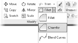
- Start the CHAMFER command from the Home tab Modify panel. If the Chamfer tool isn't visible on the Ribbon, click the down-arrow next to the Fillet tool, as shown in Figure 5.61.
FIGURE 5.61 Starting the CHAMFER command from the Modify Ribbon panel
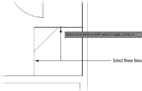
- From the Select first line or [Undo/Polyline/Distance/Angle/Trim/mEthod/Multiple]: prompt, enter D, or select Distance to set a chamfer distance.
- Enter 1′-8″ (508mm) for the first and second chamfer distances.
- Select the vertical shower edge as the first chamfer line, and the horizontal shower edge as the second chamfer edge (see Figure 5.62).
As you hover over the second line, a preview of the resulting chamfer displays, similar to the display for the FILLET command. This allows you to confirm the chamfer distance values before completing the command.
- Offset the shower polyline inward 1.5″ (38 mm), as shown in Figure 5.63.
FIGURE 5.62 Chamfering the shower edges
- Save your file as I05-18-Shower.dwg (M05-18-Shower.dwg).
Next, you'll draw the sink to the right of the shower.
Drawing the Bathroom Sink and Mirror
You'll offset a line and draw an ellipse for this fixture while you practice using the Temporary Tracking Point osnap option in the process. The Endpoint and Midpoint osnaps are still running.
- Make sure I05-18-Shower.dwg (M05-18-Shower.dwg) is open, and zoom in to the sink area with a zoom window.
- Complete the following offsets to draw the vertical limits of the sink counter and the mirror:
- Offset the top-inside wall line down 4′ (1219 mm).
- Offset the new line up 4″ (102 mm).
- Offset the top-inside wall down 4″ (102 mm).
- Complete the following offsets to draw the horizontal limits of the sink counter and the mirror:
- Offset the left inside wall 1′ 8″ (508 mm) to the right.
- Offset the same inside wall line (13 mm) to frame the counter and the mirror.
Your sink area should look like Figure 5.64.
FIGURE 5.64 The offset sink polyline
- Use the FILLET command to clean up the lines to form the sink counter and mirror. You will have to zoom in to each end of the mirror to select the correct end of the mirror's sides and fillet the lines properly. Figure 5.65 shows the partially completed sink and mirror.
 Click the down-arrow next to the Ellipse button on the Home tab Draw panel, and choose the Center option. Alternatively, you can enter EL C to start the command from the command line.
- Place the cursor near the midpoint of the bottom counter line. When the small cross appears in the osnap marker, the first tracking point is established.
- Establish the center point of the sink counter by using Object Snap Tracking:
- Move the crosshair cursor to the midpoint of the vertical line that defines the front of the counter.
- Move the cursor to the left when the cross appears in the Midpoint osnap marker. A small, dark X appears at the intersection to indicate the point that AutoCAD will use for the center point of the ellipse (see Figure 5.66).
- Click to define the center point.
FIGURE 5.65 The sink and mirror
FIGURE 5.66 Defining the center point for the ellipse
Instead of using the direct entry method to define a point with the Object Snap Tracking tool, you just used two different object snaps to define one point.
- The ELLIPSE command requires you to specify a distance for each of the major and minor axes:
- Hold the crosshair cursor directly to the right of the center point. Enter 5 (127).
- Hold the crosshair cursor directly above the center and enter 7 (178 ).
The ellipse is constructed, and the sink fixture is nearly complete.
- Hold the crosshair cursor directly to the right of the center point. Enter 5
- Use the Offset tool to offset the ellipse 1″ (25 mm) to the outside (see Figure 5.67).
Leave the view on your screen as it is for a moment.
- Save your file as I05-19-BathroomSink.dwg (M05-19-BathroomSink.dwg).
![]() WARNING Be aware that offsetting an ellipse does not create a new ellipse but instead creates a spline.
WARNING Be aware that offsetting an ellipse does not create a new ellipse but instead creates a spline.
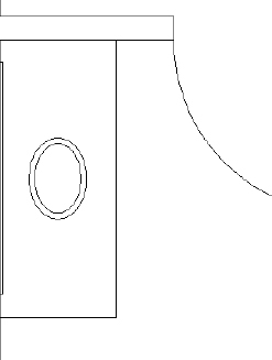
FIGURE 5.67 The completed sink fixture
The toilet and the shelves are the final fixtures necessary in the bathroom. You'll use the ELLIPSE command again, along with the RECTANG command, to draw them. You'll also learn about a couple of new display options.
Positioning the Toilet and Shelves
The shelves are a simple rectangle measuring 3′×1′ (914 mm×305 mm). The toilet consists of a rectangle and an ellipse centered between the sink and the wall. The tank is offset 1″ (25 mm) from the back wall, and it is 9″20″ (229 mm×508 mm). The ellipse representing the seat measures 18″ (457 mm) in one direction and 12″ (304 mm) in the other.
- Make sure I05-19-BathroomSink.dwg (M05-19-BathroomSink.dwg) is open.
 On the navigation bar, click the Pan button. The cursor changes to a small hand to indicate that you are in Pan Realtime mode. Position the cursor in the lower part of the drawing area, with the view still zoomed in on the sink.
- Drag the cursor up and to the right until the toilet area comes into view. The drawing slides along with the movement of the cursor. If necessary, zoom in and then pan again until you have the toilet area centered in the drawing area.
TIP You can also perform a pan, a lateral change in the viewing area with no change in zoom factor, by holding down the middle mouse button or scroll wheel. The MBUTTONPAN variable must be set to 1 (enter MBUTTONPAN1) for this functionality to be available. Now that most people use a wheel mouse, this manner of panning is becoming the preferred method. Rolling the wheel to zoom is also common.
- Right-click and choose Zoom from the context menu that opens. Alternatively, you can enter Z at the command line to execute the Zoom Realtime operation. Back in the drawing, the cursor changes to a magnifying glass with plus and minus signs.
- Position the Zoom Realtime cursor near the top of the drawing, and hold down the left mouse button. Drag the cursor down, and watch the view being zoomed out in real time. Move the cursor up, still holding down the mouse button.
Position the cursor in such a way that you have a good view of the toilet area, and then release the mouse button. Right-click again, and choose Exit from the context menu to end Zoom Realtime.
With Zoom Realtime, moving the cursor to the left or right has no effect on the view. The magnification is controlled solely by the up-and-down motion.
These zooming options are convenient tools for adjusting the view of your drawing. Let's move to the toilet first. You need to find a way to position the toilet accurately, centering it between the wall and shower. The midpoint of the left wall line isn't useful because the wall line runs behind the shower. You'll have to use a reference point to locate the starting point for the toilet tank. The lower-left corner of the tank is 5″ (127 mm) from the bottom wall and 1″ (25 mm) from the left wall. Because there is no osnap feature to define the location on the left wall, you will use the From osnap to locate the corner.
- Make sure I05-19-BathroomSink.dwg (M05-19-BathroomSink.dwg) is open.
 Start the Rectangle (RECTANG) command, and click the Snap From button in the Object Snap toolbar.
At the Base point: prompt, click the lower-left inside corner of the bathroom.
- Enter @l,5 (@25,l27) to place the first corner of the rectangle and then 9,20 (229,508).
The 9″20″ (229 mm508 mm) toilet tank is drawn centered on the left wall (see the left of Figure 5.68).
FIGURE 5.68 The toilet tank in place (left) and the completed toilet (right)
- Start the ELLIPSE command. If you start it from the Ribbon, be sure to select the Axis, End Ellipse tool from the Home tab Draw panel. The command line displays a default prompt of Specify axis end-point of ellipse or:.
Using the Specify Axis Endpoint option and the running Midpoint osnap, you can easily define the ellipse's location and first axis from one end of the ellipse to the other.
- Move the cursor near the midpoint of the right side of the tank and, when the triangle shows up there, click. This starts the ellipse.
- Hold the crosshair cursor out to the right of the rectangle, and enter 1′6 (457). This sets the first axis.
Now, as you move the crosshair cursor, you'll see that a line starts at the center of the ellipse, and the cursor's movement controls the size of the other axis.
To designate the second axis, you need to enter the distance from the center of the axis to the end of it, or half the overall length of the axis.
- Hold the crosshair cursor directly above or below the center point, and enter 6 (152).
The ellipse is complete, so you've finished the toilet (see the right side of Figure 5.68).
- To complete the fixtures, construct the shelves by drawing a 3′-0″1′-0″ (914 mm×305 mm) rectangle from the upper-right corner of the bathroom.
Figure 5.59 earlier in the chapter shows the proper orientation. Zoom out, and your completed bathroom should look like Figure 5.69.
- Save your file as I05-20-BathroomToilet.dwg (M05-20-BathroomToilet.dwg).
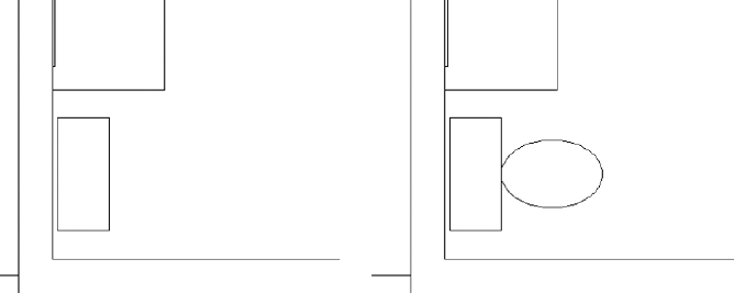
![]() TIP You can snap the features of an ellipse or a circle by using the Center or Quadrant object snaps. If an ellipse is rotated, the Quadrant points will be located at the two points where the curves are sharpest and the two points where the curves are flattest. The Quadrant snaps will always remain at the four points of a circle or arc that project vertically or horizontally from the center point regardless of the object's orientation.
TIP You can snap the features of an ellipse or a circle by using the Center or Quadrant object snaps. If an ellipse is rotated, the Quadrant points will be located at the two points where the curves are sharpest and the two points where the curves are flattest. The Quadrant snaps will always remain at the four points of a circle or arc that project vertically or horizontally from the center point regardless of the object's orientation.
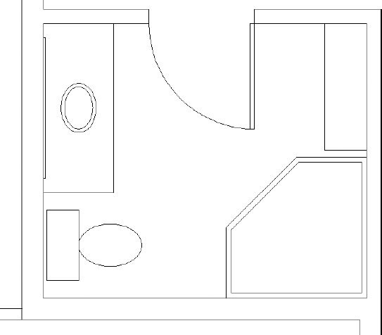
FIGURE 5.69 The completed bathroom fixtures
Drawing the Hot Tub
What is a cabin without a hot tub in which to relax? You'll complete the cabin fixtures by using a polyline to draw the outside perimeter of the hot tub, offsetting this polyline to the inside, and then filleting the appropriate corners. Here's how it's done:
- Make sure I05-20-BathroomToilet.dwg (M05-20-BathroomToilet.dwg) is open, and verify that the Polar Tracking button is still turned on in the status bar.
- Start the Polyline (PLINE) command, and click the bottom-left inside corner of the pop-out to the right of the bathroom, as shown in Figure 5.70.
- Click the endpoint to the right, on the opposite end of the pop-out.
- Move the cursor directly above the last point, and enter 4′5-5/8″ (1362) to draw the first vertical line. Refer to Figure 5.59 for the dimensions of the hot tub.
FIGURE 5.70 Starting the hot tub polyline
Earlier in this chapter, you set the Polar Tracking Increment Angle value to 45.00 in the Drafting Settings dialog box. This setting lets you easily place the cursor at 45° increments from a set point rather than at the 90° increments provided by using Ortho mode.
- Place the cursor above and to the left of the current last point, until the Polar Snap tooltip reads 135°. Then enter 3′6-7/8″ (1089) to draw the diagonal line (see Figure 5.71).
- Use the Perpendicular osnap to draw the top horizontal line from the last point to the outside of the bathroom wall.
FIGURE 5.71 Use Polar Tracking and direct input to draw the diagonal line.
- Finally, select Close or enter C at the command line to close the polyline and end the Polyline (PLINE) command.
- Use the OFFSET command to offset the polyline 4″ (102 mm) to the inside.
- Start the FILLET command, and set the Radius value to 3″ (76).
- Then fillet the two outside corners that project into the cabin (see Figure 5.72).
- Stop and then restart the FILLET command, but this time choose the Polyline option.
FIGURE 5.72 Fillet the two corners that extend into the cabin.
- Click the inside polyline to fillet all the corners at one time.
- Zoom to the drawing's extents. Your cabin should look like Figure 5.73.
- Save your drawing as I05A-FPLAYO.dwg (M05A-FPLAYO.dwg).
FIGURE 5.73 The completed floor plan zoomed to fill the screen
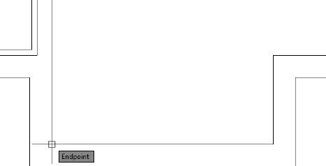
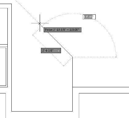
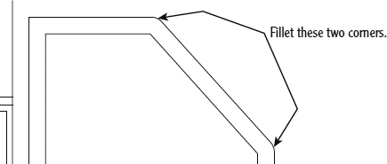
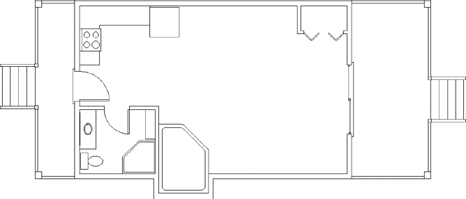
USING PAN REALTIME AND ZOOM REALTIME
The Pan and Zoom buttons are next to each other on the navigation bar. In addition to using the panel buttons, you can start Pan by entering P![]() and can start Zoom Realtime by entering Z
and can start Zoom Realtime by entering Z![]()
![]() .
.
You can also start Pan or Zoom by right-clicking at the Type a Command: prompt and then choosing Pan or Zoom from the context menu or by clicking the Pan or Zoom button in the middle of the status bar. If you try this, you'll find that it's easier than clicking the Pan or Zoom button.
![]()
Like most AutoCAD commands, the Zoom and Pan Realtime commands offer several options, including the following:
Exit Ends the Zoom Realtime or Pan Realtime command.
Pan Switches to Pan Realtime from Zoom Realtime.
Zoom Switches to Zoom Realtime from Pan Realtime.
Orbit Is a special viewing tool for 3D that is covered in later chapters.
Zoom Window Allows you to make a zoom window without first ending Pan Realtime or Zoom Realtime. You pick a point, hold down the left mouse button, and then drag open a window in your drawing. When you release the button, you're zoomed in to the window you made, and Pan Realtime or Zoom Realtime resumes.
Zoom Original Restores the view of your drawing that you had when you began Pan Realtime or Zoom Realtime.
Zoom Extents Zooms to the drawing extents.
To end Pan Realtime or Zoom Realtime, press the Esc key, press ![]() , or right-click and choose Exit from the context menu.
, or right-click and choose Exit from the context menu.
When Pan Realtime or Zoom Realtime is running, AutoCAD is in a special mode that makes the status bar invisible and, therefore, unusable.
If You Would Like More Practice…
The following are several additional exercises that will give you the opportunity to practice the skills and techniques you have learned.
Drawing the Cabin Again
As is true for almost any skill, the key to mastery is practice. Redrawing the entire cabin might seem daunting at this point, when you think of how long it took you to get here. But if you try it all again, starting from Chapter 3, “Setting Up a Drawing,” you'll find that it will take about half the time that it did the first time. If you do it a third time, it'll take half that time again. Once you understand the techniques and how the commands work, feel free to experiment with alternative techniques to accomplish tasks and with other options for the commands.
Drawing Something Else
If you have a specific project in mind that you would like to draw in AutoCAD, so much the better. Try drawing the floor plan of your home or a classroom.
Drawing Some Furniture for the Cabin
Once you put some furniture in the cabin, you'll quickly see how small it is! But it can still accept some basic furniture without seeming too cramped. You should be able to add the following:
- Kitchen—a table and chairs
- Living room—a short couch or love seat, coffee table, easy chair, and a fireplace
- Bedroom—a double bed, chest, and nightstand
Use a tape measure and go around your office or home to determine the approximate dimensions of each piece. The goal here is not so much to ensure accuracy of scale but to practice drawing in AutoCAD. Figure 5.74 shows the floor plan with these pieces of furniture. If you draw the bed shown here, try using the Spline tool for the curved, turned-down sheets. It's on the expanded Draw panel. You'll see how it works after a little experimentation.
Drawing a Gasket
Figure 5.75 shows a gasket that is symmetrical around its vertical and horizontal axes. This symmetry will allow you to use the MIRROR command to create much of the drawing.
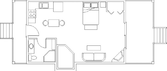
FIGURE 5.74 The floor plan with furniture
The diagram in Figure 5.76 summarizes the steps.
To draw the gasket, set Linear Units to Engineering with a precision of 0′-0.00″. Set Angular Units to Decimal with a precision of 0.00. Now, follow these steps:
- Use the LINE command to draw a rectangle 4″ wide and 3″ high.
- Offset the upper horizontal line and the left vertical line 1″ to the inside of the rectangle.
- Use FILLET with a radius set to 1″ on the upper-left corner of the original rectangle.
- Draw the circle with the 0.25″ radius, using the intersection of the two offset lines as the center.
- Erase the offset lines.
- Offset the right vertical line 2″ to the left and the bottom horizontal line 1.5″ up.
- Use FILLET with a radius of 0.50″ on the intersection of these two lines, retaining the right and lower segments.
- Trim back the lower-right corner of the original rectangle.
- Draw circles with 0.50″ and 0.75″ radii on the bottom and right sides of the shape.
- Use TRIM to remove unneeded lines.
- Use MIRROR to flip the shape down.
- Use MIRROR again to flip the shape to the right.
- Erase unneeded lines. (Each line to be erased is really two lines.)
- If you are using AutoCAD, and not LT, add the Equal constraint so that all four circles remain the same size.
- Save this drawing, naming it 05-Gasket.dwg.
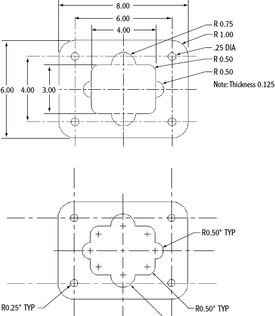
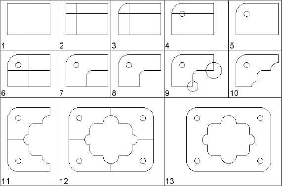
FIGURE 5.76 The 13 steps to creating the gasket
Drawing a Parking Lot
Figure 5.77 shows a parking lot partially bordered by sidewalks and streets.
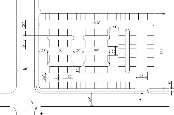
FIGURE 5.77 A parking lot
You'll get a lot of practice using the OFFSET and FILLET commands while completing this drawing. Guidelines will help you, so don't be afraid to use them. Note the tip at the end of this section. Here's a summary of the steps:
- Set Linear and Angular units to Decimal, each with a precision of 0.0.
- Set the Insertion Scale to Feet. Assume that 1 linear decimal unit equals 1″.
- Set Polar Tracking to 90°, and turn it on.
- Set the Endpoint and Midpoint osnaps to be running.
- Set Snap to 10, Grid to 0, and Drawing Limits to 400, 250.
- Zoom All.
- Use Grid and Snap to draw the large 260′170′ rectangle by using the LINE command and relative Cartesian coordinates, as you did in Chapter 3.
- Turn off Grid and Snap.
- Offset three of the lines 6′ to the outside to make the sidewalk.
- On two sides, offset the outer sidewalk line 4′ to the outside to make the curb.
- Then offset the curb lines 30′ and 40′ to make the street.
- Draw extra lines to make the street intersection.
TIP When using decimal units as feet, you don't need to use the foot sign (′) when you enter distances.
- Fillet and trim lines to create the curved corners of the intersection and sidewalks.
- Offset the lines of the inner rectangle to the inside to make guidelines for the parking strips and islands.
- Use FILLET and TRIM to finish the drawing.
- If you choose to save this drawing, name it I05-ParkingLot.dwg (M05-ParkingLot.dwg).
TIP Using the FILLET command on two parallel lines creates a semicircle connect them. Try it on the islands in the parking area.
Are You Experienced?
Now you can…
- Use the Temporary Tracking Point and Snap From object snaps to create and use tracking points
- Use the Perpendicular and Intersection osnaps
- Set up and use running osnaps
- Use the STRETCH command
- Move around the drawing area with Zoom Realtime and Pan Realtime
- Use point filters
- Use the CIRCLE and ELLIPSE commands
- Move and duplicate objects with the MOVE and COPY commands
- Use parametric drawing with geometric and dimensional constraints