
CHAPTER 6
Using Layers to Organize Your Drawing
Before the age of computers, drafters used sets of transparent overlays on their drafting tables to compose document sets of multiple disciplines. Each design discipline such as architecture, electrical, plumbing, and HVAC were drawn on an individual overlay. Each overlay had small holes punched near the corners so the drafter could position the overlay onto buttons, called registration points, that were taped to the drawing board. Because all overlays had holes punched at the same locations with respect to the drawing, information on the set of overlays was kept in alignment. Thanks to this tight integration, plan sheets were more easily produced since it was not necessary to redraw individual overlays.
To help you organize your drawing, Autodesk® AutoCAD® software provides you with an amazing tool called layers, which can be thought of as a computerized form of the transparent overlays, only much more powerful and flexible. In manual drafting, you could use only four or five overlays at a time before the information on the bottom overlay became unreadable. (Copying the drawing meant sending all the layers through the blueprint machine together.) In AutoCAD, you aren't limited in the number of layers you can use. You can have hundreds of layers, and complex CAD drawings often do.
In this chapter, you will learn to
- Create new layers, assigning colors and linetypes
- Move existing objects onto a new layer
- Manage layer visibility, storing as layer states
Using Layers as an Organizing Tool
To understand what layers are and why they are so useful, think again about the transparent overlay sheets used in hand drafting. Each overlay is designed to be printed. The bottom sheet might be a basic floor plan. To create an overlay sheet for a structural drawing, the drafter traces over only the lines of the floor plan that the overlay needs and then adds new information pertinent to that sheet. For the next overlay, the drafter performs the same task again. Each sheet, then, contains some information in common as well as data unique to that sheet.
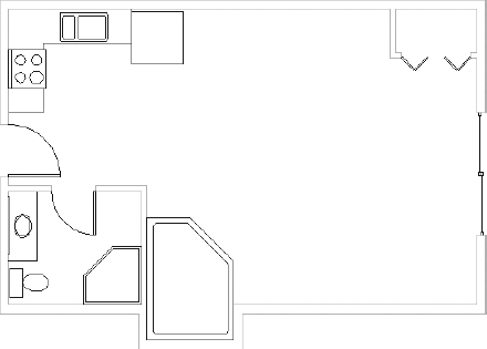
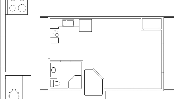
In AutoCAD, using layers allows you to generate all the sheets for a set of overlays from a single file (see Figure 6.1). Nothing needs to be drawn twice or traced. The wall layout is on one layer, and the rooflines are on another. Doors are on a third. You can control the visibility of layers so that you can make all objects residing on a layer temporarily invisible. This feature lets you put all information keyed to a particular floor plan in one DWG file. From that drawing, you can produce a series of derived drawings—such as the foundation plan, the second-floor plan, the reflected ceiling plan, and the roof plan—by making a different combination of layers visible for each drawing or drawing layout (layouts are covered in Chapter 14, “Using Layouts to Set Up a Print”). When you make a print, you decide which layers will be visible. Consequently, in a set of drawings, each sheet based on the floor plan displays a unique combination of layers, all of which are in one file.
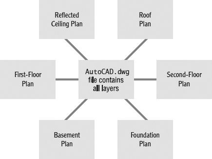
FIGURE 6.1 Several drawings can be created from one file.
![]() NOTE A typical project such as a building can easily amass more than 100 layers. Managing so many layers from a single DWG file can prove tricky at times, and so layers are but one of several organizational methods AutoCAD provides. Another method, using external references (xrefs), is a little more advanced but provides an extra level of flexibility needed for many real-world projects. You'll have the chance to explore xrefs in detail in Chapter 13,“Managing External References.”
NOTE A typical project such as a building can easily amass more than 100 layers. Managing so many layers from a single DWG file can prove tricky at times, and so layers are but one of several organizational methods AutoCAD provides. Another method, using external references (xrefs), is a little more advanced but provides an extra level of flexibility needed for many real-world projects. You'll have the chance to explore xrefs in detail in Chapter 13,“Managing External References.”
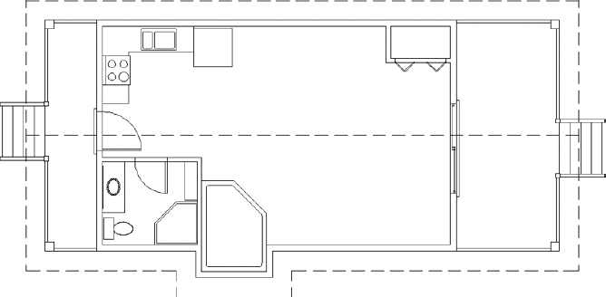
As an organizing tool, layers allow you to classify the various objects in a drawing file—lines, arcs, circles, and so on—according to the component of the building they represent, such as doors, walls, windows, dimensions, and notes. Each layer is assigned a color, and all objects placed on the layer take on that assigned default color unless you specify a different color for the objects. This lets you easily distinguish between objects that represent separate components of the building (see Figure 6.2). You can quickly tell which layer a given object or group of objects is on.
First, you'll look at the procedure for achieving this level of organization, which is to set up the new layers and then move existing objects onto them. Following that, you'll learn how to create new objects on a specific layer and find out which objects reside on which layers.
A best practice is to let layer properties (color, linetype, and so on) dictate the properties of individual objects. Avoid manually changing (overriding) the properties of the objects, such as lines and arcs, in an AutoCAD drawing.
Setting Up Layers
All AutoCAD drawings have one layer in common: layer 0. Layer 0 is the default layer in all new drawings. If you don't add any new layers to a drawing, everything you create in that drawing is on layer 0. In fact, everything so far in the cabin drawing has been drawn on layer 0.
All objects in AutoCAD are assigned a layer. In this book, I'll refer to objects assigned to a particular layer as being on that layer. You can place objects on a layer in two ways: you can move or copy them to the layer, or you can create them on the layer in the first place. You'll learn how to do both in this chapter. However, first you need to learn how to set up layers. To see how you do this, you'll create seven new layers for your cabin drawing and then move the existing objects in your drawing onto the first five of these layers. After that, you'll create new objects on the Headers and Roof layers.
Objects and layers are analogous to people and countries; just as all people must reside in some country, so too must all objects be on some layer.
In much the same way that you used the U.S. National CAD Standard (NCS) to name your DWG file in Chapter 3,“Setting Up a Drawing,” you'll also follow the NCS in naming your layers. Although filenames and layer names are each unique in many ways, the NCS naming convention is much the same for both. Before creating any layers, let's have a quick look at the basic structure we'll use to name the layers, illustrated in Figure 6.3.
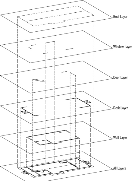
FIGURE 6.2 Separate layers combined to make a drawing
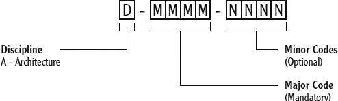
FIGURE 6.3 National CAD Standard layer-naming framework
Discipline [D] The discipline designator specifies the trade to which a layer belongs. In larger projects, it also helps establish ownership of a specific portion of a design. For instance, only members of the architectural design team use layers beginning with an A. E layers are reserved for the electrical design team, and so on. The standard discipline designators in the NCS are the same for filenames and layers and are listed in Table 6.1.
TABLE 6.1: NCS discipline designator codes
| Code | Discipline |
| G | General |
| H | Hazardous Materials |
| V | Survey/Mapping |
| B | Geotechnical |
| W | Civil Works |
| C | Civil |
| L | Landscape |
| S | Structural |
| A | Architectural |
| I | Interiors |
| Q | Equipment |
| F | Fire Protection |
| P | Plumbing |
| D | Process |
| M | Mechanical |
| E | Electrical |
| T | Telecommunications |
| R | Resource |
| X | Other Disciplines |
| Z | Contractor/Shop Drawings |
| O | Operations |
Major Discipline Designator [MMMM] At a minimum, each layer must contain both a discipline [D] code and a Major Discipline Designator [MMMM]. The Major Discipline Designator is always four characters in length, and it helps to group like objects together in the layer list. For instance, you may have multiple types of walls, but regardless of type, each wall layer would begin with A-WALL.
Minor Discipline Designator [NNNN] Sometimes you may need to classify your layers further. In the case of walls, you may have a layer for the centerline of your wall (A-WALL-CNTR), another for fire-rated walls (A-WALL-FIRE), and yet another for partial or half-walls (A-WALL-PRHT). Like the major designators, all Minor Discipline Designators should be four characters. Minor codes, unlike major designators, can be stacked together to achieve the necessary level of granularity. For instance, you might name the partial wall centerline layer A-WALL-PRHT-CNTR.
With the U.S. National CAD Standard growing in popularity, chances are that you'll have to work with drawings using its prescribed framework at some point after you begin working on your own designs. You now have a good understanding of what these standards are and, more important, how to “decode” NCS layer names when you encounter them. More information on the U.S. National CAD Standard can be found at www.nationalcadstandard.org.
Knowing every detail about NCS is not necessary to complete the exercises in this book. As in the example you're about to complete for working with layers, I'll provide all the information you need to create layers inside the framework. To begin creating new layers, take the following steps:
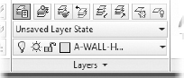
- Open AutoCAD, and then open I05A-FPLAYO.dwg (M05A-FPLAYO.dwg)—both imperial and metric versions are included in the Chapter 6 data folder. Make sure the Home tab is active and the Layers panel is in the Ribbon, centered just above the drawing area on your screen.
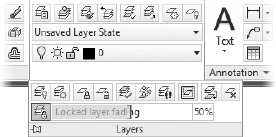
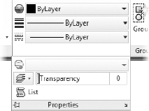
- Expand the panel and you will see that it contains several buttons, two drop-down lists, and a slider bar for controlling layers, as shown in Figure 6.4.
FIGURE 6.4 The expanded Layers panel
Several panels to the right is the Properties panel (see Figure 6.5), with four drop-down lists for controlling colors, lineweights, line-types, and plot styles, and a slider for transparency. Once again, best practices discourage changing the properties of individual objects to anything other than ByLayer/ByBlock unless absolutely necessary.
FIGURE 6.5 The expanded Properties panel
 Click the Layer Properties button on the left end of the Layers panel to open the Layer Properties Manager palette (see Figure 6.6).
A linetype is the appearance style of a line, such as Continuous, Dashed, or Dash-Dot.
FIGURE 6.6 The Layer Properties Manager palette
Notice the large open area in the middle right of the dialog box with layer 0 listed at the top of the Name column. This is the Layer List box. All the layers in a drawing are listed here, along with their current states and properties. I05A-FPLAYO.dwg (M05A-FPLAYO.dwg) has only one layer so far.
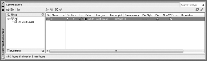
To the left of the Layer List box is the Layer Filters tree view box, where you can define which layers to display in the Layer List box. The Layer Properties Manager palette has nine buttons along the top to perform layer and filter management tasks. You'll see an Invert Filter check box at the bottom of the palette.
Before setting up new layers, look for a moment at the Layer List box. The Layer Properties Manager palette is considered modeless because you can leave it open while you continue to work on your drawing. This means that you can leave the palette open and move it away from your drawing area, where it can remain constantly open, waiting for you to input changes without having to stop to open the palette each time. Being modeless also means that your changes are instantly reflected in the drawing area, and you don't need to close the palette to see the effects of your actions.
Using the Layer List Box
Each layer has five properties—Color, Linetype, Lineweight, Transparency, and Plot Style—that determine the appearance of the objects on that layer. You may need to resize the columns to see the complete column name. You do this by placing the cursor between the columns and dragging left or right. Look at the layer 0 row in the list and notice the square and the word white in the Color column. The square is black (or white if you have a black background for your drawing area), but the name of the color is White whether the square is black or white. Continuous is in the Linetype column. This tells you that layer 0 has been assigned the color White (meaning black or white) and the Continuous linetype by default.
![]() NOTE If you set up your drawing area so that the background is white, AutoCAD automatically changes the color assigned to white in the Layer List box to black, so lines that would ordinarily appear as white on a black background will appear as black on the white background. When you then switch to a black background, the black lines change to white lines. This allows the lines to be visible regardless of the background color, and AutoCAD doesn't have to assign a new color to a layer that has been assigned the White setting when you switch background colors.
NOTE If you set up your drawing area so that the background is white, AutoCAD automatically changes the color assigned to white in the Layer List box to black, so lines that would ordinarily appear as white on a black background will appear as black on the white background. When you then switch to a black background, the black lines change to white lines. This allows the lines to be visible regardless of the background color, and AutoCAD doesn't have to assign a new color to a layer that has been assigned the White setting when you switch background colors.
The five columns to the left of the Color column are Status, Name, On, Freeze, and Lock. They each have icons or text in the layer 0 row. These columns represent some of the status modes, or states, of the layer, and they control whether objects on a layer are visible, whether they can be changed, or on which layer new objects are created. I'll discuss the visibility and status of layers later in this chapter, and I'll discuss the columns to the right of the Linetype column—Lineweight, Transparency, Plot Style, Plot, New VP Freeze, and Description—in Chapter 15, “Printing a Drawing.” Don't worry about them right now.
Creating New Layers and Assigning Colors
Let's create a few new layers, name them, and assign them colors:
- Continue using I05A-FPLAYO.dwg (M05A-FPLAYO.dwg), or open it if it's not already open.
 In the toolbar at the top of the Layer Properties Manager, click the New Layer icon. A new layer named Layer1 appears in the list. The layer's name is highlighted, which means you can rename it by entering another name now.
- Enter A-WALL
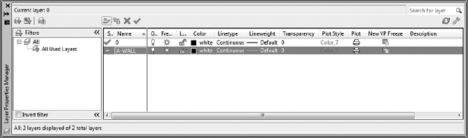
 . Layer1 changes to A-WALL. The row for the A-WALL layer should still be highlighted (see Figure 6.7).
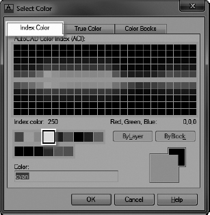
 - To open the Select Color dialog box shown in Figure 6.8, click the word white in the Color column for the A-WALL row.
Notice the three tabs at the top: Index Color, True Color, and Color Books. Each has a different selection of colors available to AutoCAD.
FIGURE 6.7 The Layer Properties Manager with a new layer named A-WALL
FIGURE 6.8 The Index Color tab in the Select Color dialog box
- Make sure the Index Color tab is selected, and click the Cyan (Index Color: 4) color swatch.
The Select Color dialog box is composed of three sets of color swatches. Color swatches for Index Colors 10 through 249 are found in the upper portion of the dialog, and colors 1–9 and colors 250–255 are found in the lower portion of the dialog.
Each color swatch has an index number associated with it. This number provides the flexibility of graphically selecting the desired color swatch or entering the numerical value associated with it. Index Colors 1–7 represent primary colors including Red, Yellow, Green, Cyan, Blue, Magenta, and White/Black. They may be specified by number or textual name.
- Click OK to close the Select Color dialog box. In the Layer List box of the Layer Properties Manager palette, you can see that the color square for the A-WALL layer has changed to cyan.
COLOR MODES
The Index Color tab provides the option to choose from the 255 distinct colors in the AutoCAD Color Index (ACI). Using the True Color tab, you can set each of the color parameters of the Red, Green, and Blue (RGB) or Hue, Saturation, and Value (HSV) components of the final color to any value between 0 and of 255, resulting in over 16 million combinations. The Color Books tab lets you access thousands of color definitions that are provided by several color standards, such as Pantone and Digital Image Correlation (DIC). These definitions are used to match the colors used on your system to physical swatches that are used by designers.
As you create your new list of layers and assign colors to them, notice how each color looks in your drawing. Some are easier to see on a screen with a light background, and others do better against a dark background. In this book, I'll assign colors that work well with a black background. If your system has a white background, you might want to use darker colors, which you can find in the array of 240 color swatches in the upper half of the Index Color tab.
You'll continue creating new layers and assigning colors to them. You'll master this procedure as you add a new layer or two in each chapter throughout the rest of the book:
- In the Layer Properties Manager palette, click the New Layer button, or right-click in the Layer List box and choose New Layer from the list of commands in the context menu.
- Enter A-DOOR to change the name of the layer.
- Pick the color square in the A-DOOR row.
- When the Select Color dialog box opens, click the color 40 square in the uppermost collection of color swatches within the Select Color dialog box. Click OK.
Repeat these steps, creating the layers shown in Table 6.2 with their assigned colors.
Pick the colors from the collection of color swatches within the Select Color dialog box, or manually enter the index color number in the Color text box at the bottom of the dialog. In the row of nine colors, the ninth swatch might not be clearly visible when it is close to the background color of the dialog box.
Notice that when a new layer appears in the Layer List box, it initially takes on the properties of the layer that was previously selected.
- Save your drawing as I06-01-CreateLayers.dwg (M06-01-CreateLayers.dwg) by choosing Application menu
 Save As AutoCAD Drawing.
TABLE 6.2: Layers and colors for the cabin drawing
Layer Name Color A-DECK-STRS 81 A-DECK 84 A-FLOR-FIXT 1 A-WALL-HEAD 11 A-ROOF Green (3) Created in earlier exercises: A-WALL Cyan (4) A-DOOR 40
![]() NOTE Blue might or might not read well on a black background. If you don't like the way it looks, try picking a lighter shade of blue from the array of 240 colors on the Index Color tab. Likewise, yellow might not read well on a lighter background; try picking a darker shade of yellow from the Index Color tab.
NOTE Blue might or might not read well on a black background. If you don't like the way it looks, try picking a lighter shade of blue from the array of 240 colors on the Index Color tab. Likewise, yellow might not read well on a lighter background; try picking a darker shade of yellow from the Index Color tab.
When finished, the layer list should have eight layers with their assigned colors in the color squares of each row (see Figure 6.9). All layers are assigned the Continuous linetype by default. This is convenient because most building components are represented in the floor plan by continuous lines, but the roof—because of its position above the walls—needs to be represented by a dashed line. Later you'll assign the Dashed linetype to the A-ROOF layer.
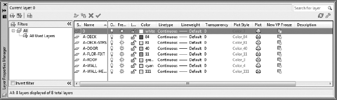
FIGURE 6.9 The Layer List box, in the Layer Properties Manager palette, with the seven new layers and layer 0
NAMING LAYERS
You can name layers in a variety of ways. With their different color assignments, layers make it possible for you to distinguish easily which objects in your drawing represent walls or other parts of your building. Most offices follow a standard for organizing layers by name and color. You've already had a chance to begin using the U.S. National CAD Standard. The International Organization for Standardization (ISO) also publishes a layering standard. Both are often adopted by architectural and engineering firms and customized to fit their specific needs.
With the cabin drawing, you'll start developing a basic set of layers. Once you learn how to manage the set you're using here, tackling more-complex layering systems will come naturally. In more-complex drawings, you might need several layers for variations of the same building component, landscape element, or machine part. You might replace the A-WALL layer, for example, with several layers, such as Existing Walls to Remain (A-WALL-E), Walls to Be Demolished (A-WALL-D), and New Walls (A-WALL-N).
When you name layers, you can use uppercase and lowercase letters, and AutoCAD will preserve them. But AutoCAD doesn't distinguish between them and treats Walls, WALLS, and walls as the same layer.
Looking at the Other Tabs in the Select Color Dialog Box
AutoCAD also supports a True Color palette and various Pantone, DIC, and RAL color groups. Although I won't cover these features in any depth in this book, let's take a quick look at them before moving on. Feel free to follow along as you explore these additional tabs by making a copy of your 05A-FPLAY1.dwg file; you won't save any changes you make in this section.
The True Color Tab With the Layer Properties Manager palette open, click one of the color swatches in the Layer List box to open the Select Color dialog box again. Then click the True Color tab. In the upper-right corner, the Color Model drop-down list displays either RGB or HSL. The display for the Red, Green, Blue (RGB) color model looks like the left side of Figure 6.10, and the Hue, Saturation, Luminance (HSL) model looks like the right side of Figure 6.10.

FIGURE 6.10 The True Color tab with the RGB color model (left) and the HSL color model (right)
The RGB option shows three horizontal color bands, one for each of the three primary colors (red, green, and blue). Move the sliders on each band to set a number from 0 to 255, or enter a number in the input box for each color. The three primary color values that combine to make up the final color appear at the bottom and on the right side, and the rectangles in the lower-right corner show the currently selected and previously selected color.
The HSL screen displays a rectangle of colors and a vertical band with a slider. Drag the crosshairs around on the rectangle. The color in the front rectangle in the lower-right corner changes as you move the crosshairs. Moving the crosshairs left or right takes the Hue value through a range of 361 values. Moving it up or down changes the percentage of saturation, or intensity, with the top of the rectangle representing 100 percent.
USING THE TRADITIONAL COLORS OF AUTOCAD
The traditional set of 255 colors for AutoCAD is set up in such a way that the first seven colors are named (Red, Blue, and so on) and numbered (1 through 7), whereas the other 248 colors have only numbers.
As you saw on the Index Color tab of the Select Color dialog box, AutoCAD has three groupings of colors: a large array of swatches in the top half and two rows of swatches below. Moving the cursor over a swatch displays its AutoCAD number below the array as well as its Red, Green, Blue (RGB) values. The RGB values indicate the amount of each color, a number from 0(none) to 255 (all), which is mixed with the other two base colors to make the selected color. Click a swatch to assign it to the layer that has been selected in the Layer Properties Manager palette.
You should avoid using colors that resemble the background color, such as colors 250–252, 18, or 8 with the default charcoal gray background. The objects with these colors could become lost visually in the drawing area. Be aware of this if your drawings might be sent to someone who doesn't use your color standards so that they can work efficiently with the drawings.
The Array of 240 Colors In the top half of the dialog box are colors numbered 10 through 249, arranged in 24 columns, each having 10 swatches.
The Row of Nine Standard Color Swatches This group includes colors 1 through 9. The first seven colors in this group also have names: Red (1), Yellow (2), Green (3), Cyan (4), Blue (5), Magenta (6), and White/Black (7). Colors 8 and 9 have numbers only. Color 7 is named White, but it will be black if you're using a white background color.
The Row of Six Gray Shades These colors are often assigned screening values (such as 50 percent, 75 percent, and so on), numbering 250 through 255. As pure color assignments, they range from almost black to almost white.
These 255 colors, plus the background color, make up the traditional AutoCAD 256-color palette. Two additional colors are in a group by themselves, Logical Colors, and are represented by buttons on the Index Color tab.
The two buttons in this grouping—ByLayer and ByBlock—represent two ways you can assign a color to objects (such as lines, circles, text, and so on) via the layer they are on or via the block of which they are part, rather than to the objects themselves. (Blocks are covered in the next chapter.) When you assign cyan to the A-WALL layer and place all objects representing walls on that layer, all wall objects are automatically assigned the color ByLayer and take on the color of their layer—in this case, cyan.
You can change the color of an object to one other than the assigned layer color by selecting the object and choosing a color from the Color Control drop-down list in the Properties panel. Setting an object's color directly is not always the best practice, however, and you should try to maintain color assignments by layer whenever practical.
The slider to the right of the rectangle controls the luminance, which, like saturation, varies from 0 percent (representing black) to 100 percent (or white). A luminance of 100 percent maximizes a color's brightness but washes out all of the hue.
The Color text box displays the currently selected color's three RGB numbers. You can also specify a color by entering numbers in the individual input boxes for Hue, Saturation, and Luminance—or the boxes for Red, Green, and Blue in the RGB screen. You can use the up- and down-arrows in these boxes to scroll through the possible settings.
If you select a color by using the RGB or HSL screen, that color appears in the Layer List box of the Layer Properties Manager palette by its three RGB numbers (see Figure 6.11).
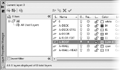
FIGURE 6.11 The Layer Properties Manager with the Roof layer assigned a color that is not part of the standard AutoCAD 255-color list
With the combination of 256 values for each of the three primary colors, you now have more than 16 million colors to choose from in AutoCAD.
The Color column might be compressed in such a way that the names of colors in the list are abbreviated. You can widen the column by dragging the divider at the right of the title farther to the right.
The Color Books Tab The Color Books tab displays the colors of the selected color book (see the image on the left side of Figure 6.12). AutoCAD has 20 color books. Each book appears in the Color Book drop-down list at the top of the tab; the current book appears in the box. Below that, a set of colors that corresponds to the position of the slider is displayed in bars. Moving the slider to a new position displays another set of colors. Click a displayed color bar to select it, and then click OK. The color appears in the Layer Properties Manager Layer List box by its identifying name and number (see the image on the right side of Figure 6.12).
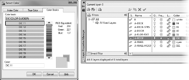
FIGURE 6.12 The Color Books tab in the Select Color dialog box (left) and the layer list with an assigned DIC number (right)
Later in the book you'll create new layers and assign them colors of your choice. Use this opportunity to explore the True Color and Color Books tabs of the Select Color dialog box, and try using some of these colors in your drawing. Keep the Layer Properties Manager palette open. You'll use it to assign linetypes in the next section.
![]()
You can delete selected layers by using the Delete Layer button, shaped like a red X, in the Layer Properties Manager palette. You can delete only empty layers—those containing no objects. You can identify empty layers in the Layer Properties Manager by the grayed-out icon in the Status column.
Assigning Linetypes to Layers
When you assign a color to a layer, you can choose any color supported by your system. This is not so with linetypes. Each new drawing has only two linetypes loaded into it by default (the Continuous and Phantom2 linetypes). You must load any other linetypes you need from an outside file:
- If it's not open already, open I06-01-CreateLayers.dwg (M06-01-CreateLayers.dwg) by clicking the Open button located on the Quick Access toolbar.
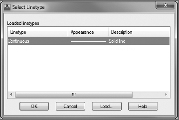
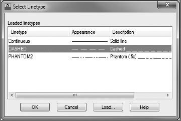
- In the Layer Properties Manager palette, click Continuous in the column for the A-ROOF layer to open the Select Linetype dialog box (see Figure 6.13). In the Loaded Linetypes list, only Continuous appears. No other linetypes have been loaded into this drawing.
FIGURE 6.13 The Select Linetype dialog box
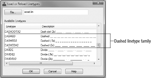
- Click Load to open the Load Or Reload Linetypes dialog box.
- Scroll down the list to the Dashed, Dashed2, and DashedX2 linetypes (see Figure 6.14). Notice how, in this family, the dashed lines are different sizes.
FIGURE 6.14 The list of available linetypes scrolled to the three Dashed linetypes
- Click DASHED in the left column, and then click OK. You're returned to the Select Linetype dialog box. The Dashed linetype has been added to the Linetype list under Continuous (see Figure 6.15).
FIGURE 6.15 The Select Linetype dialog box with the Dashed linetype loaded
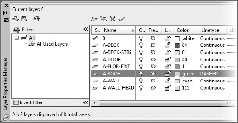
- Click DASHED to highlight it, and then click OK. In the Layer Properties Manager palette, the A-ROOF layer has been assigned the Dashed linetype (see Figure 6.16).
FIGURE 6.16 The Layer Properties Manager with the A-ROOF layer assigned the Dashed linetype
- Save your drawing as I06-02-AssigningLinetypes.dwg (M06-02-AssigningLinetypes.dwg) by choosing Application menu Save As AutoCAD Drawing.
![]() TIP You can select or deselect all the available linetypes in the Load Or Reload Linetypes dialog box by right-clicking and choosing Select All or Clear All from the context menu. You can also select multiple linetypes by holding down the Ctrl or Shift key and clicking.
TIP You can select or deselect all the available linetypes in the Load Or Reload Linetypes dialog box by right-clicking and choosing Select All or Clear All from the context menu. You can also select multiple linetypes by holding down the Ctrl or Shift key and clicking.
Learning More About Lineweight
In the Layer Properties Manager palette is a column for the Lineweight property. When you first create a layer, it is assigned the default lineweight. Just as you assigned a color and a linetype for each new layer in the cabin drawing, you can also assign a lineweight. Once assigned, lineweights can be displayed so that you can see how your drawing will look when printed.
![]() NOTE The Lineweight layer property is just one of three ways the plotted thickness of lines is commonly controlled. The oldest and generally most common method is to instruct AutoCAD to plot objects of different colors with different thicknesses. This is done by setting up a CTB file. Similarly, by using Plot Styles, you can configure an STB file to work in much the same way as CTB files. Each method has its own advantages and disadvantages, which are discussed in Chapter 15.
NOTE The Lineweight layer property is just one of three ways the plotted thickness of lines is commonly controlled. The oldest and generally most common method is to instruct AutoCAD to plot objects of different colors with different thicknesses. This is done by setting up a CTB file. Similarly, by using Plot Styles, you can configure an STB file to work in much the same way as CTB files. Each method has its own advantages and disadvantages, which are discussed in Chapter 15.
Using the Current Layer as a Drawing Tool
Now is a good time to look at what it means for a layer to be current. Notice the green check mark above the Layer List box in the Layer Properties Manager palette. The same green check mark appears in the Status column in the layer 0 row. The name of the current layer, in this case, 0, appears in the upper-left corner of the dialog box.
At any time, one, and only one, layer is set as the current layer. When a layer is current, all objects you draw will be on that layer and will take on the properties assigned to that layer unless directed otherwise. Because layer 0 is current—and has been current so far in this book—all objects that you have drawn so far are on layer 0 and have the linetype and color that are specified by default for layer 0: Continuous and White (or Black), respectively. If you make the A-WALL layer current, any new lines you draw will be Continuous and Cyan. If the A-ROOF layer is current, any new lines will be Dashed and Blue. Here's how to make the A-WALL layer the current layer:
- If it's not open already, open I06-02-AssigningLinetypes.dwg (M06-02-AssigningLinetypes.dwg) by clicking the Open button on the Quick Access toolbar.
AUTOCAD LINETYPES
The Available Linetypes list in the Load Or Reload Linetypes dialog box contains 45 linetypes. They fall into three groups:
Acad_ISO The first 14 linetypes are in the Acad_ISO family (as noted earlier, ISO is the International Organization for Standardization). They are set up to be used in metric drawings and have lineweight, or pen-width, settings.
Standard Below the ISO linetypes are eight families of three linetypes each, mixed with seven special linetypes that contain graphic symbols. Each family has one basic linetype and two that are multiples of it: one has dashes twice the size (called, for example, DashedX2), and one has dashes half the size (called Dashed2), as you saw earlier in Figure 6.14. Having an assortment of different sizes of one style of linetype is helpful for distinguishing between building components, such as foundation walls and beams, which, in addition to rooflines, might also need dashed lines.
Complex Mixed in with the Standard linetypes are seven linetypes that contain symbols, letters, or words. You can use these linetypes to indicate specific elements in the drawing, such as fences, hot-water lines, railroad tracks, and others.
It isn't difficult to create or acquire your own custom linetypes. You can do so in four ways:
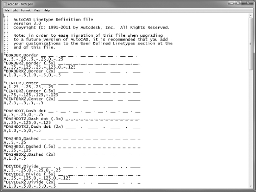
Using Notepad
Start the Windows Notepad program, and navigate to the Support folder for AutoCAD 2013. The folder is usually found at this location: C:Documents and SettingsYour NameApplication DataAutodeskAutoCAD 2013R19.0enuSupport (Windows XP), or C:UsersYour Nameappdata oamingautodeskAutoCAD 2013 19.0enusupport (Windows Vista/Windows 7). Users of Autodesk® AutoCAD LT® software will see AutoCAD LT 2013 instead of AutoCAD 2013.
Open the file named acad.lin. Its type is listed as AutoCAD Linetype Definition when you pause the cursor over the filename. It contains the definition codes for all the linetypes; they are easy to figure out. Copy an existing pattern, and modify it to create your own. I recommend that you back up the acad.lin file before making any modifications to it.
Using the Linetype Command
Enter -LINETYPE
(the hyphen [-] command prefix executes a command-line version of the command rather than a dialog-based version), and then enter C for the Create option. You'll be guided through the steps to create your own LIN file or add to an existing file. To use the LINETYPE command, you need to know the definition codes. Use Notepad until you get a feel for the codes.Using Existing Linetypes
You can often find an acceptable linetype, created by other AutoCAD users, on the Internet or in various industry publications. Many are free, and some are available at a reasonable cost. The line code is simply appended to the acad.lin file on your system.
Using Express Tools
The MKLTYPE command, found on the Express Tools tab
expanded Tools panel Make Linetype tool, automates much of the creation of custom linetypes. You can use it to draw a sample line segment with dashes, text, symbols, or the like placed over the line and quickly define a new linetype. A tip for using this tool is to draw your line at its plotted length (not scaled length). For instance, if a line segment measures 0.1″ in length when plotted, then draw the line 0.1″ in length.  Click the A-WALL layer in the Layer List box to highlight it, and then click the Set Current green check mark above the Layer List box.
Alternatively, you can double-click the A-WALL layer, or highlight it and press Alt+C. The A-WALL layer replaces layer 0 as the current layer, and the name appears in the text field at the top of the dialog box. The green check mark also appears next to the A-WALL layer in the Layer List box.
 TIP When the Status column is displayed, AutoCAD must evaluate the objects and layers several times during the drawing process. This can cause a lag when the drawing is large and the list of layers is extensive. You can hide the Status, or any other column, by right-clicking the column name and then clicking any selected option in the context menu that appears.
 Click the Auto-Hide button near the top-left corner of the Layer Properties Manager palette.
Auto-Hide causes the palette to collapse down to the title bar. You can expand it by doing one of the following:
- To expand the dialog box temporarily, pause the cursor over the title bar.
- To expand it permanently, click Auto-Hide again.
- Look at the Layer drop-down list on the Ribbon's Layers panel. Most of the symbols you saw in the Layer List box, in the Layer Properties Manager palette, are on this drop-down list. The A-WALL layer is the visible entry on the list and has a cyan square (the color you assigned to the A-WALL layer earlier). The layer is visible in this list when it's collapsed and no objects are selected in the current layer.
- Now look at your drawing. Nothing has changed because the objects in the drawing are still on layer 0.
You need to move the objects in the drawing onto their proper layers. To do this, you'll use the Layer drop-down list on the Layers panel to assign each object to one of the new layers.
Assigning Objects to Layers
When assigning existing objects in the drawing to new layers, your strategy will be to begin by selecting several of the objects that belong on the same layer and that are easiest to select. You'll reassign them to their new layer by using the Layer drop-down list. You'll then move to a set of objects that belong on a different layer or that belong on the same layer as the previously selected object but are slightly more difficult to select, and so on.
- If it's not open already, open I06-02-AssigningLinetypes.dwg (M06-02-AssigningLinetypes.dwg) by clicking the Open button on the Quick Access toolbar. Verify that the A-WALL layer is set as current as outlined in the “Using the Current Layer as a Drawing Tool” exercise earlier.
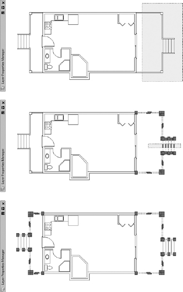
- In the drawing, click and drag a selection window down and to the left to use a crossing selection window (green box with dashed lines) to select the front deck, as shown at the top of Figure 6.17.
Grips appear, and the lines ghost (become dashed), signaling that the objects have been selected.
 NOTE See the next section, “Selecting Objects with Selection Windows,” for a complete description of the window selection process.
 - Hold the Shift key down, and select the front stairs with a crossing selection, as shown in the middle image in Figure 6.17. The stair lines appear solid again.
Selecting objects with the Shift key pressed causes objects that are already selected to become unselected (removed from the selection set), while there is no effect on unselected objects.
- Repeat the process on the rear deck so that the deck is selected but the back stairs are not. The selected components should look like the bottom image in Figure 6.17.
Notice also that, in the Layer drop-down list, the layer being displayed now is layer 0 rather than A-WALL, the current layer. When objects are selected with no command running, the Layer drop-down list displays the layer to which the selected objects are currently assigned. If selected objects are on more than one layer, the Layer drop-down list is blank.
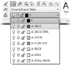
- Click the Layer drop-down list to open it (see Figure 6.18).
FIGURE 6.17 Selecting the front deck (top), deselecting the front stairs (middle), and the completed selection (bottom)
FIGURE 6.18 The expanded Layer drop-down list
- Click the A-DECK layer. The list closes. The A-DECK layer appears in the Layer drop-down list. The deck lines have been moved to the A-DECK layer and are now green.
- Press Esc to deselect the lines and remove the grips. The current layer, A-WALL, returns to the Layer drop-down list.
- Save your drawing as I06-03-AssigningLayers.dwg (M06-03-AssigningLayers.dwg) by choosing Application menu Save As AutoCAD Drawing.
This is the process you need to go through for each object so that it will be placed on the proper layer. In the next section, you'll move the thresholds and steps to the A-DECK-STRS layer. You'll select the threshold and steps by using a selection window.
Selecting Objects with Selection Windows
AutoCAD has two types of selection windows: the regular selection window and the crossing window. The crossing window is represented by dashed lines, and its interior is, by default, a semitransparent light green color. The regular window is represented by solid lines, and its interior is a semitransparent lavender color when using a white background, and blue when using a black background.
By default, AutoCAD is set up so that whenever no command is running and the prompt in the command line is Type a Command:, you can pick objects one at a time or start a regular or crossing window. If you pick an object, it is selected and its grips appear. If you select a blank area of the drawing, this starts a selection window. If you then move the cursor to the right of the point just picked, you create a regular window. If you move the cursor to the left, you create a crossing window. You'll use both crossing and regular selection windows to select the thresholds and steps:
- Make sure I06-03-AssigningLayers.dwg (M06-03-AssigningLayers.dwg) is open.
- Zoom in to the sliding glass door area. Click the Object Snap button on the status bar (or press F3) to turn it off, if it isn't already off.
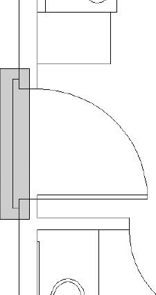
- Select the threshold for the sliding glass door by using a crossing window selection. To do that, follow these steps:
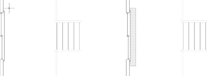
- Hold the crosshair cursor above and to the right of the upper-right corner of the sliding glass door's threshold—still inside the perimeter of the deck—as shown on the left side of Figure 6.19.
FIGURE 6.19 Starting the crossing selection window (left) and completing it (right)
- Click that point.
- Move the cursor down and to the left until you have made a tall, thin crossing window that completely encloses the right edge of the threshold and is crossed on its left edge by the short, horizontal connecting lines, as shown on the right side of Figure 6.19.
- Click again.
The three lines that make up the threshold are selected.
- Hold the crosshair cursor above and to the right of the upper-right corner of the sliding glass door's threshold—still inside the perimeter of the deck—as shown on the left side of Figure 6.19.
- Click the Layer drop-down list to open it, and then click the A-DECK-STRS layer. The front threshold is now on the A-DECK-STRS layer.
 Using the Zoom Previous tool, from the Zoom fly-out menu in the navigation bar (ViewCube on the right-hand side of the drawing area), enter Z P or simply use the scroll wheel to return to a view of the entire drawing.
When you zoom or pan with the Zoom or Pan tool, the grips are deselected. When you zoom or pan using the scroll wheel, they are not.
- Zoom in to the threshold at the back door. You will use a regular selection window to select this threshold.
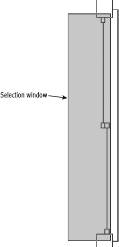
- Start a selection window slightly above and to the left of the threshold, and drag down and to the right, as shown in Figure 6.20. Be sure to enclose the horizontal threshold lines completely.
FIGURE 6.20 Selecting the threshold with a regular selection window
- Move the selected lines to the A-DECK-STRS layer the same way you did in step 3.
- Save your drawing as I06-04-SelectingObjects.dwg (M06-04-SelectingObjects.dwg) by choosing Application menu Save As AutoCAD Drawing.
Using the Quick Properties Panel
The Quick Properties panel provides access to several of the most commonly changed parameters of the selected objects. You can quickly change the selected object's layer, color, and linetype, as well as several parameters specific to the type of object selected. For example, the Radius parameter is available when a circle is selected, and the Closed option is available when a polyline is selected. When multiple objects are selected, only the parameters common to all are displayed. You will use the Quick Properties panel to change the layer of the front and back stairs:
- Make sure I06-04-SelectingObjects.dwg (M06-04-SelectingObjects.dwg) is open.
- Use crossing selection windows to select each of the lines illustrating the front and back stairs.
The grips appear, indicating the objects are selected. For lines, grips appear at each endpoint and at the midpoint of each segment; for polylines, they appear at each endpoint, and a stretch grip appears at the midpoint of each linear segment. When endpoints of lines coincide, their grips overlap. When lines are very short, their grips might appear to overlap, but that is just the result of the zoom factor.
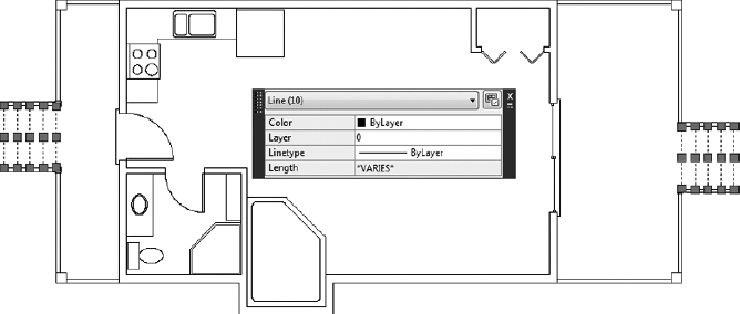
 Click the Quick Properties button in the status bar. The Quick Properties panel opens in the drawing, as shown in Figure 6.21.
FIGURE 6.21 The Quick Properties panel
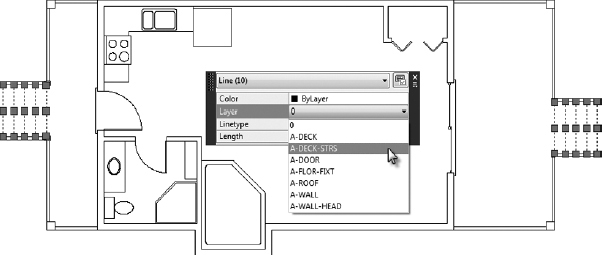
- Click in the Layer field. Then click to expand the Layer drop-down list, and choose the A-DECK-STRS layer, as shown in Figure 6.22.
FIGURE 6.22 Assigning the objects to the Steps layer
All 10 polylines representing the stairs are now on the Steps layer.
Press the Esc key to deselect the objects and remove the grips. Even when it is turned on, the Quick Properties panel disappears when no objects are selected.
Grips have other uses besides signaling that an object has been selected. You'll learn about some of these as you progress through the chapters.
- Save your drawing as I06-05-QuickProperties.dwg (M06-05-QuickProperties.dwg) by choosing Application menu Save As AutoCAD Drawing.
Selecting the Doors and Swings
To select the doors and swings, you can use crossing windows. Let's examine this task closely to learn more valuable skills for selecting objects:
- Make sure I06-05-QuickProperties.dwg (M06-05-QuickProperties.dwg) is open.
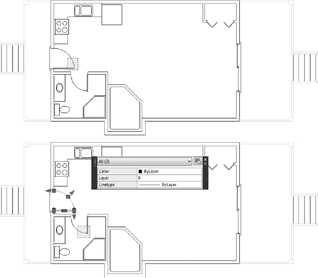
- Without any objects selected, use a crossing window to select the back door, as shown in Figure 6.23. To do this, follow these steps:
- To begin a new selection window, use the cursor to select a point in the clear space to the right of the back door.
- Move your cursor to the left (the selection window box should be green with a dashed border).
- Pick a point to the left that crosses the back door and swing, but doesn't cross the wall line, as shown at the top of Figure 6.23.
FIGURE 6.23 Using a crossing window to select the doors and swings: the back door (top) and the bathroom door (bottom)
After you complete your selection by using a crossing window, the back door and its swing highlight (dash) to indicate that they are selected. Additionally, the Quick Properties panel reappears to display the number of objects selected.
Because you selected more than one type of object (a polyline and an arc), the Quick Properties panel reads All (2) as opposed to listing the specific type of object selected. AutoCAD will list the specific type of object selected only if everything selected is of the same object type (a set of polylines, arcs, lines, and so on).
- Move to the bathroom, and select its door by using another crossing window (with the back door still selected), as shown at the bottom of Figure 6.23. To do this, follow these steps:
- Use the crosshair cursor to click in the clear space below the door, starting a new crossing window.
- With your crossing window (green with a dashed border) started, proceed to move your cursor up to select a point that crosses the bathroom door and swing without crossing any wall lines or any of the fixtures (see the bottom of Figure 6.23).
The bathroom door and swing are selected, and the quantity listed in the Quick View Properties palette updates.
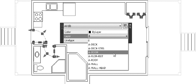
- Select the four rectangles that make up the closet doors; then open the Layer drop-down list from either the Layers panel or the Quick Properties panel and select the A-DOOR layer, as shown in Figure 6.24.
FIGURE 6.24 Using the Quick Properties panel's Layer drop-down list to change the layer of the door objects
All of the doors you selected have been moved from layer 0 to the A-DOOR layer and now display in orange (the color assigned to the A-DOOR layer).
- Press Esc to deselect the objects and remove the grips.
- Save your drawing as I06-06-DoorSwings.dwg (M06-06-DoorSwings.dwg) by choosing Application menu Save As AutoCAD Drawing.
For the sliding glass door, it's awkward to create a crossing window from left to right because positioning the pickbox between the threshold lines and the sliding door can be difficult. In this situation, use a regular window to select the objects:
- Make sure I06-06-DoorSwings.dwg (M06-06-DoorSwings.dwg) is open.
- Zoom in to the area of the sliding glass door.
- Use a regular selection window to select the sliding glass door at the front of the cabin. To do this, follow these steps:
- Select a point to the left of the balcony opening. By selecting a point, a new selection window is started.
- Move your cursor, and pick a point to the right of the sliding glass window until the right edge of the window (blue background with solid boundary line) is just inside the wall, but just to the right of the sliding glass door itself (as shown in Figure 6.25).
FIGURE 6.25 Using a regular selection window to select the sliding glass door
The entire sliding glass door assembly is selected, but not the jambs, walls, threshold, or balcony. Many grips appear, 13 lines make up the sliding glass door, and each has three grips: a grip at each endpoint and a grip at each midpoint. Many of the grips overlap.
- Open the Layer drop-down list, and select the A-DOOR layer.
- Press Esc to deselect the objects and remove the grips.
- Then use the Zoom Extents tool found by selecting the View tab Navigate panel Zoom Extents tool from the zoom fly-out menu, or you can double-click the middle-button/scroll wheel on your mouse.
You have a full view of the floor plan, where each of the doors are red and are found on the A-DOOR layer.
- Save your drawing as I06-07-SlidingDoor.dwg (M06-07-SlidingDoor.dwg) by choosing Application menu Save As AutoCAD Drawing.
The next task is to move the kitchen and bathroom counters and fixtures and the hot tub onto the A-FLOR-FIXT layer. In doing this, you'll learn how to deselect some objects from a group of selected objects.
Selecting the Kitchen and Bathroom Fixtures
Sometimes it's more efficient to select more objects than you want and then deselect those you don't want. You'll see how this is done when you select the kitchen and bathroom fixtures:
- Make sure I06-07-SlidingDoor.dwg (M06-07-SlidingDoor.dwg) is open.
- To start a crossing window, pick a point in the kitchen area just below and to the right of the refrigerator but above the back door.
- Move the cursor to the top left and up until the upper-left corner of the crossing window is to the left of the left edge of the counter and inside the back wall, as shown at the top of Figure 6.26.
- When you have your cursor placement correct, click that point. The entire kitchen counter area and fixtures are selected.
- Move down to the bathroom, and pick a point inside the shower near the bottom-right corner, being careful not to touch any lines with the crosshair cursor.
- Move the crosshair cursor up and to the left, until the lower-left corner of the crossing window is in the middle of the sink (see the middle of Figure 6.26). When you have the selection window positioned this way, click that point. All the bathroom fixtures, except the mirror, are selected.
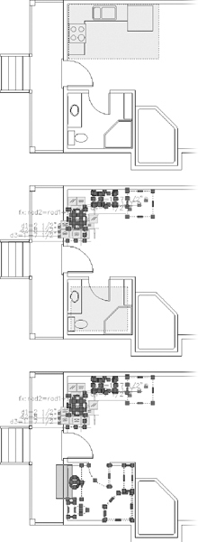
FIGURE 6.26 A crossing window to select the kitchen objects (top), another crossing window to select the bathroom objects (middle), and a regular selection window selecting the mirror (bottom)
- From left to right, drag a regular window that encompasses the mirror, as shown at the bottom of Figure 6.26. It doesn't matter whether the selection window surrounds objects that are already selected.
- To complete the selection set, drag a crossing selection window that crosses both of the hot tub polylines that encroach into the living room.
- Hold down the Shift key, and then pick the selected door and swing in the bathroom.
Be careful to not pick a grip. As you pick the objects, their lines become solid again and their grips disappear, letting you know they have been deselected, or removed from the selection set (see Figure 6.27). Be sure to pick the inside wall lines in the kitchen at locations where they don't coincide with the stove or counter.
FIGURE 6.27 The completed selection set after removing the door swing and back wall line
- Release the Shift key.
- Open the Layer drop-down list, and select the A-FLOR-FIXT layer. The fixtures are now on the A-FLOR-FIXT layer and are color 11.
- Press the Esc key to deselect the objects.
- Save your drawing as I06-08-SelectingFixtures.dwg (M06-08-SelectingFixtures.dwg) by choosing Application menu Save As AutoCAD Drawing.
The last objects to move onto a new layer are the wall lines. It won't be easy to select the wall lines by using conventional methods because so many other objects in the drawing are in the way. However, because the only objects remaining on layer 0 are the walls for your cabin, you can use the Select Similar command.
Selecting Walls by Using the Select Similar Command
In the last several exercises, you learned how to select objects by using both a regular window and a crossing window. Although there are several ways to make regular and crossing selections (such as when you used the Fence option to trim lines in Chapter 2, “Learning Basic Commands to Get Started”), these remain the two fundamental ways to select multiple objects at once inside AutoCAD. The Select Similar option expands on that concept and adds a way to select multiple objects that have some similarity all at once.
To try out this selection method, you'll select objects whose similarity is that they are lines on layer 0. That is, all lines currently drawn on layer 0 will be selected. Although only lines are drawn on layer 0, if you had both arcs and lines on layer 0 and used the Select Similar command on a line, only the lines would be selected. Again, because lines are the only objects on layer 0, the Select Similar command is perfect for this particular application.
- Make sure I06-08-SelectingFixtures.dwg (M06-08-SelectingFixtures.dwg) is open.
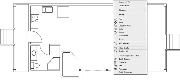
- Select any line currently drawn on layer 0 that represents a wall within your cabin (see Figure 6.28).
FIGURE 6.28 Choosing the Select Similar right-click menu option after selecting a single wall line
- Being careful not to deselect the line on layer 0, right-click and select the Select Similar option, as shown in Figure 6.28. The Select Similar command selects all of the lines on layer 0.
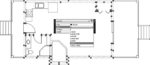
- Use the Quick Properties panel to select the A-WALL layer (see Figure 6.29).
FIGURE 6.29 Using the Quick Properties panel to select the A-WALL layer after using the Select Similar command to select every line on layer 0
- Save the current drawing as I06-09-SelectSimilar.dwg (M06-09-SelectSimilar.dwg) by using the Save icon on the Quick Access toolbar.
SELECTING OBJECTS IN YOUR DRAWING
As you select objects in the cabin drawing to move them onto their prescribed layers, you use various selection tools. Mastering these important tools will greatly enhance your performance as an AutoCAD user. As you select objects by picking them and windowing them, you're building a selection set. You might want to remove objects from that selection set later. Here is a summary of the basic selection tools that you have used so far, with a couple of additions.
Picking
This is the basic, bottom-line selection tool. Click the line, circle, or other object to select it. If no command is running, grips appear on the selected object, and the object becomes dashed. If a command is running and you're being prompted with Select objects:, grips don't appear, but the object is selected and ghosts (changes to a dashed appearance).
Removing Objects from a Selection Set
At some point, you'll find it more efficient to select more objects than you want and then remove the unwanted ones. You can do this in three ways:
- To remove a couple of objects, hold down the Shift key and pick the objects.
- To remove objects from the selection set, hold down the Shift key and use one of the selection window types.
- If a command is running, enter R, and then use the selection tools (picking, windows, and so on) without the Shift key to remove objects from the selection set.
If you are in a command and need to add objects back to the selection set after removing some, enter A![]() . This puts you back into selection mode, and you can continue adding objects to the set.
. This puts you back into selection mode, and you can continue adding objects to the set.
Turning Off and Freezing Layers
You can make layers invisible either by turning them off or by freezing them. When a layer is turned off or frozen, the objects on that layer are invisible. These two procedures operate in almost the same way and perform about the same function, with one significant difference: objects on frozen layers cannot be selected with the All option, while objects on layers that are off can be selected. For example, if you enter E![]() A
A![]()
![]() to erase all objects, all the visible and invisible objects on the layers turned off are deleted, while the objects on frozen layers remain in the drawing but are still invisible. Here is a good rule to follow: if you want a layer to be invisible for only a short time, turn it off; if you prefer that it be invisible semipermanently, freeze it.
to erase all objects, all the visible and invisible objects on the layers turned off are deleted, while the objects on frozen layers remain in the drawing but are still invisible. Here is a good rule to follow: if you want a layer to be invisible for only a short time, turn it off; if you prefer that it be invisible semipermanently, freeze it.
For the task at hand, you'll turn off all layers except for the A-WALL and A-DOOR layers to reveal a more simplified look of your floor plan. Afterward, you'll learn how to restore the visibility of all layers in your drawing at once.
- Make sure I06-09-SelectSimilar.dwg (M06-09-SelectSimilar.dwg) is open.
- Click the Layer Properties button on the Layers panel to open the Layer Properties Manager palette, or expand the palette if it is still collapsed on your screen.
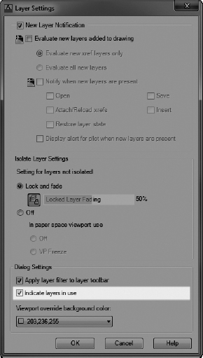
 Click the Settings button in the upper-right corner of the Layer Properties Manager palette. The Layer Settings dialog box opens.
- In the Dialog Settings group near the bottom, enable the Indicate Layers In Use option (see Figure 6.30), and click OK.
FIGURE 6.30 Enabling the Indicate Layers In Use option from the Layer Settings dialog box
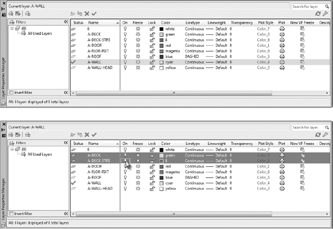
Notice that layer 0 is still first in the list and that the other layers have been reorganized alphabetically (see the top of Figure 6.31).
Also, notice the icons in the Status column:
- A green check mark signifies that the A-WALL layer is current.
- The light blue layer icons signify that those layers (0, A-DECK, A-DECK-STRS, A-DOOR, and A-FLOR-FIXT) now have objects on them.
- The light gray layer icons tell you that those layers (A-ROOF and A-WALL-HEAD) don't have any objects on them.
Because the A-WALL layer is current and has a green check mark in the Status column, you can't tell whether the layer has any objects on it. You have to make a different layer current and then check whether the Walls icon is blue or gray.
The status of layers will appear in the Status column in the Layer Properties Manager only if that feature was enabled in the Layer Settings dialog box (see step 4).
- Click the A-DECK layer to highlight it.
- Then hold down the Shift key and click the A-DECK-STRS layer. Both the A-DECK and A-DECK-STRS layers should be highlighted within the Layer Properties Manager.
- Move the arrow cursor over to the On column, which has a lit lightbulb as a symbol for each layer row.
- Click one of the lightbulbs of the selected layers (see the bottom of Figure 6.31).
FIGURE 6.31 The layers, now listed alphabetically (top), and after turning off the selected layers (bottom)
 The lit lightbulb symbols all change to unlit bulbs for the A-DECK and A-DECK-STRS layers.
 - Collapse or close the Layer Properties Manager or simply move it out of the way. Both the deck (A-DECK) and the stairs leading up to the deck (A-DECK-STRS) are invisible (see Figure 6.32).
FIGURE 6.32 The floor plan without the deck shown
 From the Home tab Layers panel, select the Off tool and then click any object on the A-FLOR-FIXT (color 11) layer. By selecting an object on the A-FLOR-FIXT layer, you have graphically turned that layer off, making the objects on it invisible (see the top of Figure 6.33).
- Press Esc to end the Off command.
 To restore the visibility of all layers at once by turning them on, expand the Home tab Layers panel and select the Turn All Layers On tool. The bottom of Figure 6.33 shows the result.
Two of your layers, A-ROOF and A-WALL-HEAD, still have no objects on them because these components haven't been drawn yet. You'll draw the headers now.
Drawing the Headers
Most door and window openings don't extend to the ceiling. The portion of the wall above the opening and below the ceiling is the header. The term comes from the name of the beam inside the wall that spans the opening. In a floor plan, wall lines usually stop at the door and window openings, but you need lines across the gap between jamb lines to show that an opening doesn't extend to the ceiling; hence, you'll create the header.
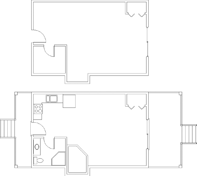
FIGURE 6.33 The floor plan after turning off the A-FLOR-FIXT layer (top) and with the visibility of all layers restored (bottom)
To draw headers directly onto the correct layer, you need to make the A-WALL-HEAD layer current. As you've seen, you can use the Layer Properties Manager palette. But you can also use a shortcut, the Layer drop-down list in the Layers panel, which you have just been using to move objects from one layer to another:
- Make sure I06-09-SelectSimilar.dwg (M06-09-SelectSimilar.dwg) is open.
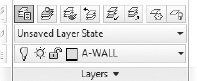
- From the Home tab Layers panel, click the Layer drop-down list to display a list of layers, or click the down-arrow button on the right end.
The drop-down list opens, displaying a list of the layers in your drawing. If you have more than 10 layers, a scroll bar becomes operational, giving you access to all the layers.
- Click the A-WALL-HEAD layer. The drop-down list closes.
If the list of layers in the layer drop-down is not sorted alphabetically, try increasing the value of the MAXSORT system variable.
A-WALL-HEAD appears in the list box (see Figure 6.34), telling you that the Headers layer has replaced Walls as the current layer.
FIGURE 6.34 The A-WALL-HEAD layer is now shown as current in the Layers panel.
- Make sure object snaps (osnaps) are enabled by clicking the Object Snap button on the status bar or by pressing F3. The Endpoint, Midpoint, and Intersection osnaps are now active. If they aren't, right-click the Object Snap button and, in the context menu, click the osnaps that you want active.
 From the Home tab Layers panel, click the Freeze tool. As you begin to draw the headers, other objects, such as the doors and thresholds, may get in the way. You'll use the Freeze tool to select the layers graphically instead of opening the Layer Properties Manager to freeze the respective layers.
- At the Select an object on the layer to be frozen or: prompt, click one door or door swing (A-DOOR) and one threshold (A-DECK-STRS). All the objects on the Doors and Steps layers temporarily disappear.
- Press Esc to end the Freeze command.
You need to draw two parallel lines across each of the three openings, from the endpoint of one jamb line to the corresponding endpoint of the jamb on the opposite side of the opening.
- To start the LINE command, enter L or click the Line button from the Home tab Draw panel.
- Move the cursor near the upper end of the left jamb for the back door until the colored snap marker appears at the upper-left endpoint of the jamb line, and then click.
- Move the cursor to the left end of the lower jamb, and click to complete the line.
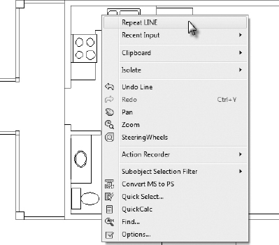
- Right-click once to open a context menu near your cursor (see Figure 6.35).
FIGURE 6.35 The right-click context menu for accessing recent and common commands
- Choose Enter from the menu, and then right-click again to open another context menu at the cursor, as shown in Figure 6.36.
FIGURE 6.36 A second right-click context menu with additional commands available
- Choose Repeat LINE.
- Move to the right endpoint of the upper jamb line for the back door.
- With the same technique used in steps 6 through 12, draw the lower header line across the opening. You can see the results in the left image of Figure 6.37.
FIGURE 6.37 The header lines drawn for the back door opening (left) and for the rest of the doorway openings (right)
- Keep using the same procedure to draw the rest of the header lines for the remaining three doorway openings. The floor plan will look like the right image of Figure 6.37.
- Save this drawing as I06-10-Headers.dwg (M06-10-Headers.dwg).

Drawing the Roof
You've seen that the Layer drop-down list is a shortcut that allows you to pick a different layer quickly as the current layer and to turn off or turn on individual layers. You've also learned how to use the Layer Properties Manager palette to create new layers or to turn off many layers at a time. You'll learn about another tool for changing the current layer as you draw the rooflines.
Before you start to draw the rooflines, refer to Figure 6.38 and note the lines representing different parts of the roof:
- Eight eaves lines around the perimeter of the building, representing the lowest edge of the roof
- One ridgeline, representing the peak of the roof
FIGURE 6.38 The floor plan with the rooflines
The roof for the cabin is called a double-pitched roof because the panels slope down to the eaves on only two sides. You'll start by drawing the eaves.
Creating the Eaves
Because the roof extends beyond the exterior walls the same distance on all sides of the building, you can generate the eaves lines by offsetting the outside wall lines:
- Make sure I06-10-Headers.dwg (M06-10-Headers.dwg) is open.
- Open the Layer drop-down list, and select the A-ROOF layer to make it current.
 Start the OFFSET command from the Home tab Modify panel Offset tool, or enter O from the command line. Then follow these steps:
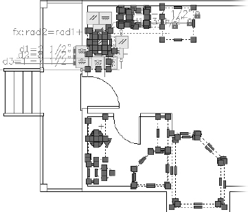
- At the Specify offset distance or prompt, press the down-arrow and select the Layer option (see the left image of Figure 6.39).
FIGURE 6.39 Choosing the Layer option (left) and the Current option (right)
- The second prompt reads Enter layer option for offset objects. Press the down-arrow and select the Current option, or enter C to instruct AutoCAD to create offsets on the current layer (A-ROOF), as shown in the right image of Figure 6.39.
- At the Specify offset distance or prompt, press the down-arrow and select the Layer option (see the left image of Figure 6.39).
- Enter 1′6 (457) when prompted to specify the offset distance.
- Pick the upper-left, vertical, outside handrail polyline, and then pick a point to the left of that polyline to offset it to the outside. The L-shaped offset line is on the Roof layer.
- Move to another side of the cabin, pick the lower-right, outside handrail polyline, and offset it to the outside.
- Repeat this process for the three outside wall lines that define the pop-out on the bottom of the cabin and the short, horizontal, outside wall line to the left of the pop-out.
You have one offset element on each side of the cabin (see Figure 6.40).
FIGURE 6.40 One outside wall line is offset to each side of the building.
- Press to end the OFFSET command.
Start the FILLET command from the Home tab
Modify panel Offset tool.
- Verify that the fillet radius is set to zero by entering R and then 0 (or use the Shift key to override the radius value).
- Starting with the horizontal portion of the upper-left, L-shaped poly-line, click two of these newly offset lines that are on adjacent sides of the building.
Work around the building in a clockwise manner, being sure to click the half of the line nearest the corner where the two selected lines will meet (see the top of Figure 6.41).
FIGURE 6.41 Picking lines to fillet one of the eaves' corners (top) and the result (bottom)
The lines extend to meet each other and form a corner (see the bottom of Figure 6.41). The FILLET command ends.
- Press to restart the FILLET command, and then enter M to select the Multiple option.
Pick the remaining pairs of adjacent lines that will meet at the corners. When you try to fillet the final section, you'll get a warning at the command prompt that reads Lines belonging to polylines must be consecutive or separated by one segment, and the command prompt returns to Select first object or:.
Although it looks as though the polyline has a single gap between two adjacent segments, in actuality the gap is between the first (vertical) segment and the eighth (horizontal) segment. You can't use the PEDIT command's Close option yet because it would add an additional, diagonal segment from the polylines' existing endpoints. You could explode the polyline into individual lines, execute the fillet, and then use PEDIT to join them, but in this case you'll use the polylines' grips to close the gap.
- Press the Esc key to terminate the FILLET command.
- Click the polyline to select it and display its grips.
You can temporarily turn off the Quick Properties panel by clicking the X in the upper-right corner, or you can turn it off completely by clicking the Object Properties button in the status bar.
STARTING OBJECT SNAPS
By now, you know that you can activate a nonrunning osnap by using the Ctrl+right-click menu or the Object Snap toolbar or by typing the shortcut keys. From now on, I'll simply instruct you to activate a specific object snap, and you can use the method you prefer.
- Click the grip at the open left endpoint of the horizontal segment (see the left of Figure 6.42).
The grip turns red to signify that it is hot (active) and can be manipulated.
- Start the Perpendicular osnap, place the cursor over the open vertical segment, and then click when the marker appears. The horizontal line is extended to the location perpendicular to the vertical line.
FIGURE 6.42 Using the grip to move the horizontal endpoint (left) and the vertical endpoint (right)
- Select the grip at the open end of the vertical segment to make it hot.
- Then click the open end of the horizontal line to move the first end-point there (see the right of Figure 6.42).
- Finally, use the JOIN command on the Home tab expanded Modify panel to select each of the rooflines and create a closed polyline.
Visually, there is no difference in the perimeter of the roof, but AutoCAD no longer sees an open polyline. Closed polylines are almost always preferable in case you need to extrude a 2D object into a 3D object, and using closed polylines is generally a cleaner drafting practice. Your completed roof perimeter should look like Figure 6.43.
- Save this drawing as I06-11-DrawingRoof.dwg (M06-11-DrawingRoof.dwg).
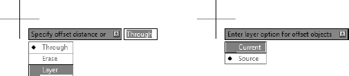
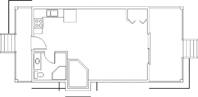
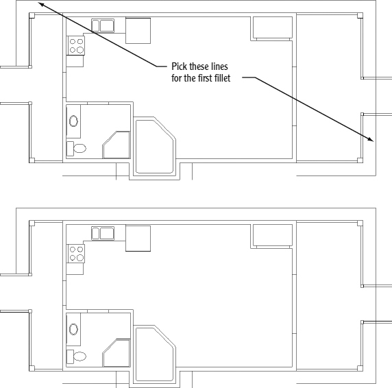
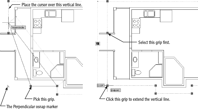
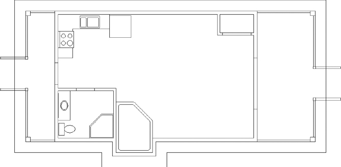
FIGURE 6.43 The completed eaves lines after filleting
Setting a Linetype Scale Factor
Currently it's hard to see that the lines drawn on the A-ROOF layer are indeed dashed, as specified in the Layer Properties Manager. Unless you zoom in to a line on the A-ROOF layer, the lines look continuous, like the objects on the other layers in your drawing. This is because the dashes inside the DASHED linetype are set up to be ![]() (13 mm) long with
(13 mm) long with ![]() (6 mm) spaces. Using the line-type scale, or LTSCALE as many call it, you will tell AutoCAD how to scale your linetypes.
(6 mm) spaces. Using the line-type scale, or LTSCALE as many call it, you will tell AutoCAD how to scale your linetypes.
Interestingly enough, a drawing's linetype scale is actually controlled by three separate LTSCALE variables:
LTSCALE (Linetype Scale)
PSLTSCALE (Paper Space Linetype Scale)
MSLTSCALE (Model Space Linetype Scale)
With three variables to choose from, it's probably easy to see how one of the most debated topics among AutoCAD users is what setting should be used for these variables. I'll show you two of the more popular ways people choose to set these variables. The first is more of a manual approach, and the second is what I like to call LTSCALE Auto Pilot.
In comparison to the LTSCALE variable itself, both PSLTSCALE and MSLTSCALE are relative newcomers. Consequently, many users still prefer to calculate their LTSCALE value manually. A common architectural scale is ![]() . To make the dashes plot (print)
. To make the dashes plot (print) ![]() long (as desired), divide 12″ (1 foot) into
long (as desired), divide 12″ (1 foot) into ![]() (12″
(12″ ![]() = 24).
= 24).
If you set LTSCALE to 24, PSLTSCALE to 0, and MSLTSCALE to 0, the dashes for the DASHED linetype assigned to the A-ROOF layer will plot ![]() long. A big drawback to this method is that your dashes will be
long. A big drawback to this method is that your dashes will be ![]() long only if you plot your drawing at a scale of
long only if you plot your drawing at a scale of ![]() . Plotting your drawing at a scale of
. Plotting your drawing at a scale of ![]() would translate to the dashes in your drawing plotting
would translate to the dashes in your drawing plotting ![]() long.
long.
![]() NOTE The imperial to metric conversion is approximated.
NOTE The imperial to metric conversion is approximated.
If you're confused by this method of calculating and setting the various LTSCALE variables, you're not alone. The method I'm going to show you next is both a little easier and more modern than the first way I showed you. The following steps demonstrate how to put LTSCALE on Auto Pilot:
- Make sure I06-11-DrawingRoof.dwg (M06-11-DrawingRoof.dwg) is open.
- Enter LTSCALE or LTS. The prompt in the command-line interface reads Enter new linetype scale factor <1.0000>:.
- Enter 1 to set the linetype scale factor to 1. Nothing changes quite yet, as the default value for LTSCALE is 1.
- Enter PSLTSCALE.
- When prompted to Enter new value for PSLTSCALE:, enter 1.
- Enter MSLTSCALE.
- When prompted to Enter new value for MSLTSCALE:, enter 1.
- Change the Annotation Scale of your drawing by clicking the Scale drop-down on the status bar.
 Select
  from the list of scales, as shown in Figure 6.44.
If you aren't satisfied with the dash size, as illustrated in Figure 6.45, change the Annotation Scale as you did in steps 8 and 9. An advantage to this method is that you can preview any scale (by changing the Annotation Scale) without affecting any drawing sheets in your project. Layout viewports have an Annotation Scale much like the Annotation Scale property you just changed for model space. With LTSCALE, PSLTSCALE, and MSLTSCALE each set to 1, AutoCAD will automatically calculate the correct linetype scale based on the properties of each individual view.
FIGURE 6.44 The Annotation Scale list
FIGURE 6.45 The eaves lines on the Roof layer with visible dashes
Save this drawing as I06-12-LinetypeScale.dwg (M06-12-LinetypeScale.dwg).
If your linetypes do not dash after you've changed the Annotation Scale, enter REA
 at the command line to perform a REGENALL.
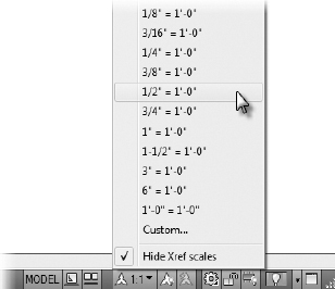
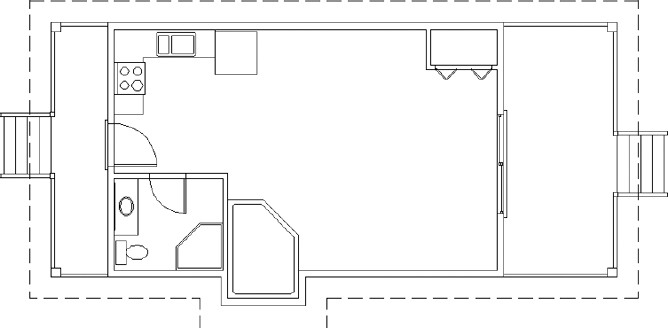
Drawing the Ridgeline
To finish the roof, you'll draw a single line to represent the peak of the roof that extends from the front of the cabin to the back. Because of the pop-out, the roof is not symmetrical, so the ridgeline will be centered on the two longest vertical sections.
Look at the Linetype drop-down list on the Properties panel (see Figure 6.46). A dashed line with the name ByLayer appears there. ByLayer tells you that the current linetype will be whatever linetype has been assigned to the current layer. In the case of the A-ROOF layer, the assigned linetype is Dashed. (You'll read more about ByLayer later in this chapter.)
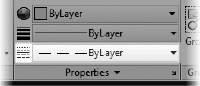
FIGURE 6.46 The Linetype drop-down list
To draw the ridgeline, follow these steps:
- Continue using I06-12-LinetypeScale.dwg (M06-12-LinetypeScale.dwg) or open it if it's not already open.
- Start the LINE command, and activate the Midpoint object snap.
- Start the line from the midpoint of the right vertical roofline.
- Start the Perpendicular osnap, and then click the vertical roofline on the opposite side of the cabin.
- Terminate the LINE command.
Your cabin should look like Figure 6.47.
- Save this drawing as I06-13-Ridgeline.dwg (M06-13-Ridgeline.dwg).

FIGURE 6.47 The completed roof
Using the Layer Walk Tool
Before saving the next drawing, you will use the Make Object's Layer Current button (Home tab ![]() Layers palette) to make the A-DOOR layer current. You will then use the Layer Walk tool to verify the contents of each layer by isolating them one at a time:
Layers palette) to make the A-DOOR layer current. You will then use the Layer Walk tool to verify the contents of each layer by isolating them one at a time:
- Make sure I06-13-Ridgeline.dwg (M06-13-Ridgeline.dwg) is open.
 Expand the Layers panel, and click the Pin button in the lower-right corner. This causes the panel to stay open after the cursor moves off it instead of autocollapsing.
 Verify that all layers are in a Thaw state by using the Thaw All Layers tool found on the Home tab Layers panel.
 Click the Make Object's Layer Current button in the top row of buttons in the Layers panel. You'll get the Select object whose layer will become current: prompt.
- Pick one of the doors or swing lines. The A-DOOR layer replaces A-ROOF in the Layer drop-down list, telling you the A-DOOR layer is now the current layer.
TIP The Make Object's Layer Current button works two ways. You can click the button and then select the object whose layer will become current, or you can select an object that's on the target layer and then click the button. If you use the latter method to select multiple objects, they must all reside on the current layer or the tool will prompt you to select an object.
 Click the LayerWalk button in the extended Layers panel to open the LayerWalk dialog box, shown in Figure 6.48.
FIGURE 6.48 The LayerWalk dialog box
- Select a layer other than layer 0, and the drawing area shows only the objects on that layer.
- Use the up- and down-arrows to “walk” through the drawing's layers, verifying that the objects reside on the correct layers. The top of Figure 6.49 shows the cabin drawing with the A-FLOR-FIXT layer selected.
FIGURE 6.49 Displaying the contents of the A-FLOR-FIXT layer (top) and the A-WALL layer (bottom)
If you double-click a layer name, that layer stays displayed even when it isn't highlighted, and an asterisk appears next to the layer name. Figure 6.49 (bottom) shows the cabin drawing with the A-ROOF layer selected and the A-WALL layer locked on.
- Close the LayerWalk dialog box.
 Click the Unpin button to unpin the expanded Layers panel.
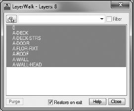
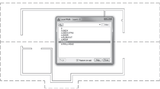
By drawing the rooflines, you have completed most of the exercises for this chapter. The cabin floor plan is almost complete. In the next chapter, you'll complete the floor plan by using a grouping tool called a block to place windows in the external walls. The rest of this chapter contains a short discussion about color, linetypes, and lineweights and how they work with layers and objects. You'll also look at the Action Recorder feature to record and play back repetitive tasks.
Setting Properties of Layers and Objects
This section covers a few concepts you should consider when assigning properties to layers and objects.
Selecting Colors for Layers and Objects
First you must decide whether you prefer a light or dark background color for the drawing area. This is generally a personal preference, but the lighting in your work area can be a contributing factor. Bright work areas usually make it difficult to read monitors easily, and with a dark background color on your screen in a brightly lit room, you'll often get distracting reflections on the screen. Eyestrain can result. Darkening your work area will usually minimize these effects. If that's not possible, you might have to live with a lighter background.
Next, look at the colors in your drawing. If the background of your drawing area is white, notice which colors are the easiest to read. For most monitors, yellow, light gray, and cyan are somewhat faded, while blue, green, red, and magenta are easily read. If your drawing area background is black, the blue is sometimes too dark to read easily, but the rest of the colors that you have used so far usually read well. This is one reason that most users prefer a dark background color.
Assigning a Color or a Linetype to an Object Instead of a Layer
You can also assign properties of layers, such as color, linetype, and lineweight, to objects. For example, think about the A-ROOF layer. It's assigned the Dashed linetype. A line on the A-ROOF layer can be assigned the Continuous linetype, even though all other lines on the Roof layer are dashed. The same is true for color and lineweight. Occasionally, this makes sense, especially for linetypes, but that is the exception rather than the rule. To make such a change, follow these steps:
- Select the line.
- Open the Properties palette.
- Change the linetype from ByLayer to the linetype of your choice.
You can also use the Properties toolbar to make quick changes to an object's appearance.
![]() TIP It's a generally accepted best practice that an object's color, line-type, lineweight, and transparency should all be ByLayer. However, it's not uncommon to receive a drawing with lots of object overrides. Use the SETBYLAYER command to clean this up quickly.
TIP It's a generally accepted best practice that an object's color, line-type, lineweight, and transparency should all be ByLayer. However, it's not uncommon to receive a drawing with lots of object overrides. Use the SETBYLAYER command to clean this up quickly.
In this chapter, you have seen how to assign colors and linetypes to layers in order to control the way objects on those layers appear. That is the rule to follow. When objects are assigned properties that vary from those of their layer, the result can be confusing to someone working with your drawing file, because the objects don't appear to be on their assigned layer. If the object's properties match those of another layer, you can mistakenly think the object is on that layer.
Making a Color or a Linetype Current
If you look at the Properties panel for a moment, you'll see lists to the right of the Layer drop-down list. The first three of these lists are the Color, Linetype, and Lineweight controls. You use these tools to set a color, linetype, or lineweight to be current. When this is done, each object subsequently created will be assigned the current linetype, lineweight, and/or color, regardless of which linetype, line-weight, and color have been assigned to the current layer. If, for example, the A-DOOR layer is set as the current layer, and the Dashed linetype and green color are assigned as current, any lines drawn are dashed and green but still on the A-DOOR layer. This isn't a good way to set up the system of layers, linetypes, and colors because of the obvious confusion it will create in your drawing, but beginners often accidentally do this.
The best way to maintain maximum control of your drawing is to keep the current linetype, lineweight, and color set to ByLayer, as they are by default. When you do this, colors and linetypes are controlled by the layers, and an object takes on the color and linetype of the layer it is on. If this configuration is accidentally disturbed and objects are created with the wrong color or linetype, you can correct the situation without too much trouble:
- Reset the current color, lineweight, and linetype to ByLayer by using the drop-down lists on the Properties panel.
- Select all problem objects.
- Use the Properties palette or Quick Properties panel to change the linetype, lineweight, or color to ByLayer.
The objects will take on the color, lineweight, and linetype of the layer to which they have been assigned, and you can quickly tell whether they are on their proper layers.
Using the Action Recorder
![]() One of the most useful tools in AutoCAD is the Action Recorder. With this feature, you can perform repetitive tasks and save the steps to a file, called a macro, which can be played back anytime you need to repeat those steps in any drawing. For example, if you need to draw several countersunk holes in a plate at a specified distance, you can prompt the user for a start point, angle, diameter, and spacing, and then let AutoCAD do the work. The Action Recorder creates the macros for you without the need for you to learn macro programming.
One of the most useful tools in AutoCAD is the Action Recorder. With this feature, you can perform repetitive tasks and save the steps to a file, called a macro, which can be played back anytime you need to repeat those steps in any drawing. For example, if you need to draw several countersunk holes in a plate at a specified distance, you can prompt the user for a start point, angle, diameter, and spacing, and then let AutoCAD do the work. The Action Recorder creates the macros for you without the need for you to learn macro programming.
For this example, you will add two new layers to your drawing and then make one of them the current layer. The practice of adding your standards to a drawing from someone else (a client, contractor, and so on) is common. Follow these steps to create the action:
- Click the Manage tab from the Ribbon to display a series of panels that contain tools for managing a drawing's interface and standards.
 Click the Record button (Manage tab Action Recorder panel).
The Record button changes to a Stop button, and the panel pins itself open, as shown in Figure 6.50. A large red dot appears at the cursor to remind you that the actions are being recorded.
You'll use the command line to start the LAYER command. The - prefix starts the command without opening the Layer Properties Manager palette.
- Enter -LAYER.
- Enter N or pick New from the list that appears at the cursor.
FIGURE 6.50 The Action Recorder panel as it appears when the actions are being recorded
- Enter L-PLNT to name the new layer. Both methods for selecting an option work equally well.
- Select the New option again, and enter E-POWR to create and name the new layer.
- Choose the Set option.
- Enter E-POWR to make the E-POWR layer current and end the LAYER command.
- Click the Stop button to discontinue recording the actions. Your Action Recorder panel should look like Figure 6.51.
FIGURE 6.51 The Action Recorder after creating the new layers and setting the current layer
- In the Action Macro dialog box that opens (see Figure 6.52), enter New_Layers in the Action Macro Command Name field, and add a description if you like.
FIGURE 6.52 The Action Macro dialog box
 WARNING Special characters, such as spaces or slashes, are not permitted in action filenames.
 - Click OK, and the macro is saved as New_Layers.actm in the C:Usersusernameappdata
oamingautodeskautocad 2013
19.0enusupportactions folder. (A copy is also available on this book's web page.)
TIP Those using Windows XP can find the macro in C:Documents and SettingsYour NameApplication DataAutodeskAutoCAD 2013R19.0enuSupportActions.
- Unpin the Action Recorder panel so that it can collapse.
- Open a new drawing file.
- Make sure the New_Layers macro name appears in the Available Action Macro field, and click the Play button, as shown in Figure 6.53.
FIGURE 6.53 Playing the New_Layers macro in the Action Recorder panel
- Click Close when the Action Macro dialog box indicates that the macro has run to completion (see Figure 6.54).
FIGURE 6.54 The Action Macro dialog box
- Switch to the Home tab, and then open the Layer drop-down list in the Layers panel. You will see the new layers the macro created.
- Save your cabin drawing as I06-14-ActionMacro.dwg (M06-14-ActionMacro.dwg).
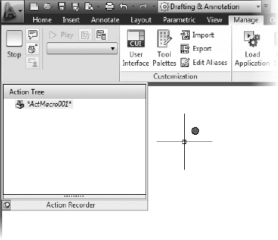
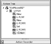
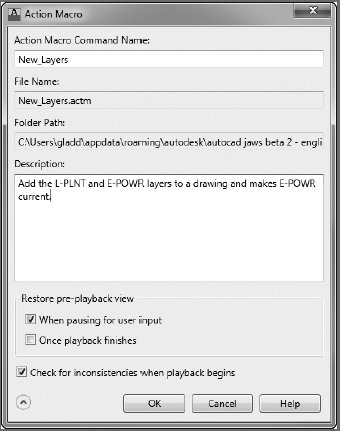
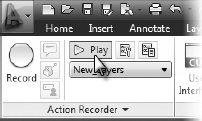
As you can see, action macros are easy to record and can save you time when repetitive tasks are required. You could have easily set layers' colors, linetypes, or on/off statuses, or performed other layer-related tasks. The Action Recorder is quite powerful and can save a great amount of time when you use it to create macros specific to your needs. In the next section, you will look at a method of saving and recalling all the settings for the layers in your drawings. You can close the blank drawing without saving the changes.
Creating Layer States
Even a drawing that reads well when printed may get cluttered in the viewports, and it can become difficult to execute a command properly. Often, you will find yourself freezing or turning off the same layers to execute a specific task and then making them visible again. In the course of your workday, you might issue the same sequence of layer commands dozens of times. To make this task more efficient, layer states are available. Layer states are named settings in which you can save the conditions of the layers, such as On, Frozen, or Current, and restore them through the Layer States Manager dialog box. The following exercise demonstrates how to create a layer state that shows only the floor plan and not the roof or fixtures:
- Continue using the drawing you used to complete the previous Action Recorder exercise, or open I06-14-ActionMacro.dwg (M06-14-ActionMacro.dwg).
- In the Cabin drawing, make layer 0 the current layer.
- From the Layer drop-down list or the Layer Properties Manager palette, freeze the A-ROOF and A-FLOR-FIXT layers.
- On the Layers panel, click the Layer States drop-down list, which currently shows Unsaved Layer State, and click Manage Layer States, as shown in Figure 6.55.
FIGURE 6.55 Accessing the Layer States Manager
The Layer States Manager dialog box opens (see Figure 6.56).
- Click the New button to create a new saved layer state.
- In the New Layer State To Save dialog box, enter Floor Plan in the New Layer State Name field. If you like, enter a description for the layer state as well (see Figure 6.57).
FIGURE 6.56 The Layer States Manager dialog box
FIGURE 6.57 Saving a layer state in the New Layer State To Save dialog box
- Click the OK button when you are finished.
- The new layer state appears in the Layer States Manager dialog box, as shown in Figure 6.58. Click the Close button to close the Layer States Manager dialog box.
- Thaw the Roof and Fixtures layers. The objects on those layers become visible again.
FIGURE 6.58 The Layer States Manager dialog box showing the new layer state
- Open the Layer States Manager dialog box again.
 Click the More Restore Options button—the right-facing arrow at the bottom-right corner—to display additional options.
The items shown in the Layer Properties To Restore section are, when checked, the features of the layer state that are affected when it is restored. It is important to note that if you make changes to a layer's color or lineweight, those changes are lost when the layer state is restored if those features are checked here.
- Uncheck the Color, Linetype, and Lineweight options (see Figure 6.59), and then click the Restore button.
The Roof and Fixtures layers are frozen again (see Figure 6.60), and Floor Plan appears in the Layer State drop-down list.
- Save this drawing as I06A-FPLAYO.dwg (M06A-FPLAYO.dwg).
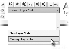
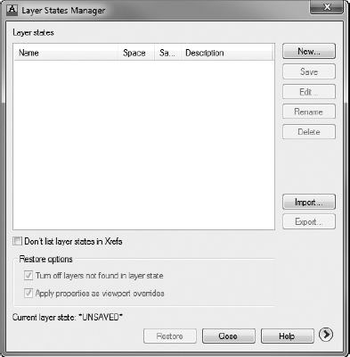
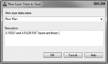
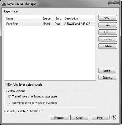
As you can see, saving layer states can reduce the number of steps it takes to restore a specific set of layer properties. In a complex drawing, it isn't uncommon to have a dozen or more saved layer states.
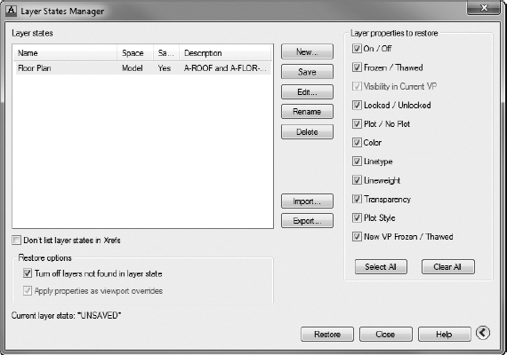
FIGURE 6.59 The Layer States Manager dialog box with the restore options selected

FIGURE 6.60 The cabin with the Roof and Fixtures layers frozen
USING THE LAYER STATES MANAGER
You also use the Layer States Manager dialog box to manage existing layer states. Here are its primary features:
Layer States List Box Displays a list of previously saved layer states.
Restore Button Restores the layer state that is highlighted in the Layer States list box.
Edit Button Opens the Edit Layer State dialog box, where the current layer state's properties are edited.
Delete Button Deletes a layer state. This doesn't affect the current layer setup.
Import Button Imports an LAS file, from a DWG, DWS, or DWT file, as a new layer state in the current drawing.
Export Button Exports the chosen saved layer state to be saved as an LAS file.
To modify a layer state, restore it to be the current layer state and then change it. To rename a layer state, highlight it, click its name, and enter the new name.
If You Would Like More Practice…
All trades and professions that use AutoCAD have their own standards for naming and organizing layers. The following suggestions are designed to encourage you to apply this chapter's concepts to your individual use of the program.
Experimenting with Linetypes and Linetype Scales
Choose Save As to save I06A-FPLAYO.dwg (M06A-FPLAYO.dwg) to a new file called I06A-FPLAY9_Linetype.dwg (M06A-FPLAY9_Linetype.dwg). Then experiment with the linetypes and linetype scales (Global and Object) to get a feel for how the linetypes look and how the scales work. You won't be using this practice file again, so feel free to draw new objects that will make it convenient for you to work with linetypes. Here are some suggestions for linetypes to experiment with:
- Dashed2 or Dashed (0.5)
- DashedX2 or Dashed (2)
- Hidden (as compared to Dashed)
- Phantom
- DASHDOT
- Fenceline2
- Hot_Water_Supply
Here is a summary of the steps to get a new linetype into your drawing:
- Create a new layer or highlight an existing layer.
- In the Layer Properties Manager, click the linetype name in the Linetype column for the chosen layer.
- Click the Load button.
- Highlight a linetype in the list and click OK.
- Highlight the new linetype in the Linetype Manager dialog box and click OK.
- Make the layer with the new linetype the current layer, and then click OK to close the Layer Properties Manager.
- Draw objects.
Once you have a few linetypes represented in the drawing, open the Linetype Manager dialog box and experiment with the Global and Object linetype scale factors.
Setting Up Layers for Your Own Trade or Profession
Open a new drawing, and set up approximately 10 layers that you might use in your own profession. Assign colors and linetypes to them. Most activities that use CAD have some layers in common, such as Centerline, Border or Titleblock, Drawing Symbols, Dimensions, and Text or Lettering.
Are You Experienced?
Now you can…
- Create new layers and assign them a color and a linetype
- Load a new linetype into your current drawing file
- Move existing objects onto a new layer
- Turn layers off and on
- Freeze and thaw layers
- Make a layer current, and create objects on the current layer
- Use the Layer Walk tool to verify that objects are on the proper layers
- Reset the linetype scale factor globally or for a selected object
- Record action macros
- Create layer states