13
Wireless Communications Blocks Integration
We designed key wireless communication blocks and tried to optimize each parameter such as complexity, throughput, latency, and power consumption in Part II. Although each block is optimized, it is not easy to integrate them and find an optimal solution of wireless communication systems at high level. Thus, we discussed radio planning and link budget analysis in Chapter 11. We looked into the wireless communication system design flows and wireless communication system design considerations in Chapter 12. In this chapter, we will take a look at top level view of wireless communication systems, review 4G standards, and integrate each wireless communication block.
13.1 High Level View of Wireless Communications Systems
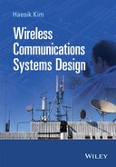
In order to exchange or broadcast data between communication systems, we need a standardized protocol. If not, it is difficult to understand the contents even if we receive a signal correctly. Thus, the International Standard Organisation (ISO) defined the Open Systems Interconnection (OSI) 7 layer model for network protocols. Although it is not widely used in industry and many standardization groups prefer a simpler model, it is good conceptual model characterizing the internal functions of wireless communication and network systems. The advantage of the OSI 7 layer model is that each layer is regarded as a black box and one layer transfers its input/output to another layer above/below the layer. Thus, we can develop each layer independently and update each layer without a whole system change. The OSI 7 layer model is organized in the specific order from the top layer to the bottom layer. The bottom layer is the physical layer. It defines how the data is transmitted and received over the communications media such as copper cable, fiber, and radio. The physical layer deals with physical properties of the media, mechanical properties of the data connection (pin layout, cable specification, etc.), signal presentation (waveform, encoding, etc.), and control signals. The physical layer protocol includes Ethernet PHY, RS-232, IEEE802.11 PHY, 3GPP PHY, and so on. The layer 2 is the data link layer. It defines how to make a reliable link. The data link layer is composed of two sub-layers: Media Access Control (MAC) layer and Logical Link Control (LLC) layer. The MAC layer is to distinguish the physical devices using the MAC address and the LLC layer is to detect errors in received frames. The data link layer protocol includes IEEE802.11 MAC, 3GPP MAC, Point-to-Point Protocol (PPP), and so on. The layer 3 is the network layer. It is in charge of routing packets across the network. For example, one big video file is divided into many packets and then each packet is labeled by a network address. Each packet is transmitted from one node to another node in the same network. The network layer as one of the complicated layers divides packets and manages network addresses. The network layer protocol includes Internet Protocol (IP), Internet Control Message Protocol (ICMP), Internet Group Management Protocol (IGMP), and so on. The layer 4 is the transport layer. It is an intermediate layer between lower layers and higher layers. It hides the complexities of lower layers from the higher layers and provides a reliable link by data retransmission. The transport layer protocol includes Transmission Control Protocol (TCP), User Datagram Protocol (UDP), and so on. The layer 5 is the session layer. It manages the connection or session between nodes. The session layer protocol includes Secure Shell (SSH), Secure Sockets Layer (SSL), and so on. The layer 6 is the presentation layer. It allows the nodes/devices to exchange information in the same language. The presentation layer protocol includes Moving Picture Experts Group (MPEG), Joint Photographic Experts Group (JPEG), Server Message Block (SMB), and so on. The top layer is the application layer. It allows an end user to access the network resources and provides an interface between end users and networks. The application layer protocol includes Hypertext Transfer Protocol (HTTP), File Transfer Protocol (FTP), Domain Name System (DNS), and so on. Figure 13.1 illustrates OSI 7 layer.

Figure 13.1 OSI 7 layer
In this book, the wireless communication system design mainly meant the physical layer system design. The upper layer is about network design issues. As we can see Figure 13.1, the physical layer is implemented mainly in hardware. The data link layer is implemented in both hardware (for a low MAC) and software (for a high MAC). The upper layers are implemented in software. The OSI 7 layer enables us to design wireless communication systems with interoperability. However, the disadvantage is the lack of collaboration between layers. The strict boundaries between layers prevent us to optimize a whole wireless communication system. We face the limitation of the system performance improvement. Thus, cross-layer design [1] was proposed in order to overcome the limitation. The key idea is to break the strict boundaries and permit collaboration and joint optimization between layers. The goal of the cross-layer design is to improve security, Quality of Service (QoS), and mobility [2, 3]. However, this approach is confronted with several challenges such as the lack of the unified cross-layer design, cross-layer signaling, and overhead for cross-layer signaling. Thus, the layered communication architectures are still widely used in 4G communication systems.
The physical layer of wireless communications is composed of Radio Frequency (RF) front-end and digital transmitter/receiver. The RF front-end is placed between an antenna and Digital to Analogue Converter (DAC)/Analogue to Digital Converter (ADC). It converts from a low/high frequency signal (baseband/passband signal) to a high/low frequency signal (passband/baseband signal). The RF front-end is composed of impedance matching circuit, Power Amplifier (PA), Low Noise Amplifier (LNA), Band Pass Filter (BPF), mixer, Local Oscillator (LO), and Phase Locked Loop (PLL). Figure 13.2 illustrates the typical RF front-end transmitter and receiver.

Figure 13.2 RF front-end transmitter (a) and receiver (b)
The incoming signal of the RF front-end transmitter is converted to high frequency signal in a mixer and local oscillator and amplifies the signal in the power amplifier. Then, the antenna radiates the electromagnetic waves in the air. In the RF front-end receiver, the antenna receives the electromagnetic waves and the band pass filter selects the desired signal. The received signal basically includes a noise. Thus, LNA amplifies the received signal while it reduces the effect of the noise. The received signal is converted to a low-frequency signal in a mixer and local oscillator. After that, the analogue signal is converted to digital signal in ADC. Now, the received signal is processed in digital domain.
The digital transmitter/receiver is divided into the inner part and the outer part. The outer transmitter/receiver includes source coding/decoding, scrambling/descrambling, formatting/deformatting, error correction coding/decoding, interleaving/deinterleaving, and so on. They deal with digital data representing digital signals. For example, the soft decision data of Turbo decoding comes from the inner receiver. The soft decision data express how likely the data is—0 or 1. After Turbo decoding, we have the hard decision data and cannot represent how likely it is. Thus, the outer receiver mainly deals with the digital data representing digital signals. On the other hand, the inner transmitter/receiver includes modulation/demodulation, IFFT/FFT, synchronization, channel estimation, equalization, MIMO, and so on. They deal with digital data representing analogue signals. Thus, the main purpose of the inner receiver compensates a noise and tries to recover the original transmitted signals. Then, the outer receiver corrects or detects an error. If the data integrity is confirmed, we send the data to an upper layer. If not, data retransmission is requested. Figure 13.3 illustrates the abstracted transmitter and receiver.

Figure 13.3 Abstracted transmitter (a) and receiver (b) architecture
13.2 4G Physical Layer Systems
There have always been technology competitions to meet the requirements and secure a share of the new market. For example, Ultra-Wideband (UWB) development was divided into two technology camps: Direct Sequence (DS) UWB led by Motorola and Multi-Band OFDM led by Intel. Likewise, in order to meet the 4G system requirements (max. 1 Gbps for a low mobility communication and max. 100 Mbps for a high mobility communication) by International Telecommunication Union Radio communications sector (ITU-R), there are two technology camps: Long-Term Evolution (LTE) by the 3rd Generation Partnership Project (3GPP) and Worldwide Interoperability for Microwave Access (WiMAX) by the Institute of Electrical and Electronics Engineers (IEEE). Although both technologies do not meet these requirements, they are called 4G communication systems. Both physical layer technologies are quite similar. Their key physical layer technologies include MIMO, Orthogonal Frequency-Division Multiple Access (OFDMA), AMC, Turbo code, and so on. On the other hand, the differences are channel bandwidth, frame structure, uplink modulation, and so on. In this chapter, we will take a look at both LTE and WiMAX and compare their physical layer technologies.
13.2.1 LTE
The LTE was initiated in 3GPP Release 8 [4]. Some key technologies in the 3GPP Release 8 include Single Carrier Frequency Division Multiple Access (SC-FDMA) [5], Advanced MIMOs, and six channel bandwidths (1.4, 3, 5, 10, 15, and 20 MHz). The 3GPP continues the revision of the LTE standard from release 8 to release 12. In a cellular system, many users should share finite radio resources. Multiple access schemes are an essential part of the cellular system. They divide radio resources and allocate users to a predetermined time and frequency slot. The multiple access schemes allow us to manage multiple users without interferences and maximize the radio resource utilization. Roughly speaking, Frequency Division Multiple Access (FDMA) divides the total spectrum into narrow channels which are allocated to multiple users. The FDMA system has a simple hardware architecture and is used in analogue systems such as Advanced Mobile Phone System (AMPS) and Nordic Mobile Telephone (NMT). However, its spectrum efficiency is very low and it is not suitable for variable rate transmission. In Time Division Multiple Access (TDMA), each channel is divided into time slots which are allocated to multiple users. The TDMA system has a higher spectral efficiency and provides us with variable rate transmission. However, it needs a long guard interval and synchronization sequence. The TDMA is used in 2G systems. Global System for Mobile communications (GSM) combines TDMA and FDMA. In GSM, each user is allocated in specific bandwidth and time. In Code Division Multiple Access (CDMA), multiple users simultaneously transmit and receive data in same frequency and time. Using spread spectrum technology, each user is identified. The CDMA system has many advantages: high spectral efficiency, flexible resource allocation, soft handoff, and so on. On the other hand, some disadvantages are self-jamming, near far problem, and overall decrease in service quality when the number of user increases. The 2G system such as IS-95 used CDMA and the 3G system adopted Wideband CDMA (W-CDMA). OFDMA is based on the OFDM technique and assigns a subset of subcarriers to multiple users. The LTE multiple access scheme is based on OFDMA for downlink and SC-FDMA for uplink. Although their multiple access schemes are different, they have common frame structures. The type 1 frame structure is defined for Frequency Division Duplexing (FDD) mode. The FDD mode uses two distinct frequency bands for downlink (from a base station to mobile stations) and uplink (from mobile stations to a base station). In order to isolate the transmit/receive signals from the receive/transmit signals, a duplex-filter is used. Figure 13.4 illustrates the type 1 frame structure. The duration of the type 1 radio frame is 10 ms. The radio frame consists of 10 subframes (1 ms) and each subframe consists of 2 slots (0.5 ms). Each slot consists of seven OFDM symbols when the normal cyclic prefix is employed.

Figure 13.4 LTE type 1 (FDD) frame structure
The type 2 frame structure is defined as Time Division Duplexing (TDD) mode. The TDD mode assigns a single frequency band to both a transmitter and a receiver but the signal is transmitted/received in different times. The expensive duplex filters are not required in the TDD mode so that the hardware cost of the TDD mode is substantially less than the FDD mode. However, the adjacent channel interferences of the TDD mode are much higher than the FDD mode. Figure 13.5 illustrates the type 2 frame structure. The type 2 frame consists of two 5 ms half frames. Subframes consist of three type transmissions: downlink transmission, uplink transmission and special subframe transmission (downlink pilot time slot (DwPTS), guard period (GP) and uplink pilot time slot (UpPTS)).

Figure 13.5 LTE type 2 (TDD) frame structure
The type 2 frame configuration is determined by one of the seven difference configurations as shown in Table 13.1. In the table, D, U, and S represent downlink transmission, uplink transmission, and special subframe transmission, respectively.
Table 13.1 LTE type 2 (TDD) frame configuration
| Type 2 frame configuration | Switch point periodicity (ms) | Subframe number | |||||||||
| 0 | 1 | 2 | 3 | 4 | 5 | 6 | 7 | 8 | 9 | ||
| 0 | 5 | D | S | U | U | U | D | S | U | U | U |
| 1 | 5 | D | S | U | U | D | D | S | U | U | D |
| 2 | 5 | D | S | U | D | D | D | S | U | D | D |
| 3 | 10 | D | S | U | U | U | D | D | D | D | D |
| 4 | 10 | D | S | U | U | D | D | D | D | D | D |
| 5 | 10 | D | S | U | D | D | D | D | D | D | D |
| 6 | 5 | D | S | U | U | U | D | S | U | U | D |
The OFDMA uses time and frequency resources of the available bandwidth. A physical Resource Block (RB) is defined as consisting of 12 consecutive subcarriers in frequency domain and 7 consecutive OFDM symbols in time domain. It is the smallest element of resource allocation and contains 84 resource elements (=12 × 7). Each RB occupies 180 kHz (=12 × 15 kHz (the subcarrier spacing Δf )) in frequency domain and 0.5 ms (one slot) in time domain. When the channel bandwidth is 5 MHz, we can use maximum 27.7 RB (=5 MHz/180 kHz). However, we use 25 RB for the 5 MHz channel bandwidth. Figure 13.6 illustrates resource blocks.

Figure 13.6 Resource grid and resource blocks
In Figure 13.6, ![]() represents the number of resource blocks in the downlink and uplink.
represents the number of resource blocks in the downlink and uplink. ![]() represents the number of subcarriers and the value is 12 for standard operation.
represents the number of subcarriers and the value is 12 for standard operation. ![]() represents the number of OFDM or SC-FDMA symbols and the value is 7 or 6 for standard operation. Table 13.2 summarizes the physical resource block parameters.
represents the number of OFDM or SC-FDMA symbols and the value is 7 or 6 for standard operation. Table 13.2 summarizes the physical resource block parameters.
Table 13.2 Physical resource block parameters
| Downlink | Uplink | |||
|
|
|
|
|
|
| Normal CP (Δf = 15 KHz) | 12 | 7 | 12 | 7 |
| Extended CP (Δf = 15 KHz) | 12/24 (Δf = 7.5 KHz) | 6/3 (Δf = 7.5 KHz) | 12 | 6 |
The LTE air interface consists of physical channels and physical signals. They are defined in 3GPP documentations [6]. The physical channels correspond to a set of resource elements conveying information from upper layers and they are mapped onto transport channels. The transport channels are Service Access Points (SAP) between MAC and PHY. The LTE supports two types of downlink physical channels: control channels and data channels. Physical Downlink Shared Channel (PDSCH) carries the user data. Since a high data rate is required, a high order modulation (such as 64 QAM) and spatial multiplexing are used in this channel. Physical Downlink Control Channel (PDCCH) conveys the control signal to the mobile station (or User Equipment (UE)). The control signals include H-ARQ information, resource allocation, and UL scheduling grant. Multiple PDCCH can be transmitted in one subframe. Physical Control Format Indicator Channel (PCFICH) is used to indicate how many OFDM symbols are reserved for PDCCH. It is transmitted in every subframe. Physical Hybrid ARQ Indicator Channel (PHICH) carries H-ARQ information in response to UL transmission. Physical Broadcast Channel (PBCH) carries cell-specific information such as Random Access Channel (RACH). This channel is always provided with 1.08 MHz bandwidth. Physical Multicast Channel (PMCH) carries multicast data. Table 13.3 summarizes LTE downlink physical channels.
Table 13.3 LTE downlink physical channels
| Downlink channels | Full name | Modulation | Purpose |
| PDSCH | Physical downlink shared channel | QPSK, 16 QAM, 64 QAM | Carries user data |
| PDCCH | Physical downlink control channel | QPSK | H-ARQ, resource allocation and UL scheduling grant |
| PCFICH | Physical control format indicator channel | QPSK | Indicates number of PDCCH OFDM symbols per subframe |
| PHICH | Physical hybrid ARQ indicator channel | BPSK | Carries H-ARQ information (ACK/NACK) |
| PBCH | Physical broadcast channel | QPSK | Carries cell information |
| PMCH | Physical multicast channel | QPSK, 16 QAM, 64 QAM | Carries multicast data |
The LTE physical signals use physical resource elements but do not carry any information from/to upper layers. There are two types of the LTE downlink physical signals: Synchronization Signals (SSs) and Reference Signals (RSs). The synchronization signals are classified into primary and secondary synchronization signals. The Primary Synchronization Signal (PSS) is generated from Zadoff-Chu (ZC) sequence with length 62 in frequency domain and mapped to the seventh OFDM symbol in slots 0 and 10. The Secondary Synchronization Signal (SSS) is an interleaved concatenation of two binary sequences with length 31 and mapped to the sixth OFDM symbol in slot 0 and 10. The concatenated sequence is scrambled with a scrambling sequence by PSS. Figure 13.7 illustrates PSS and SSS in one frame.

Figure 13.7 PSS and SSS
The LTE access procedure (cell search and synchronization) is carried out using PSS and SSS. Once a UE (or a mobile station) is switched on, it must start looking for an LTE cell and acquire all information required to register. Since the UE is unaware of the downlink channel configuration, cell information should appear on a consistent place regardless of the downlink channel configuration. Thus, PSS and SSS are transmitted in specific slots of each downlink frame. In order to search and select an LTE cell, we follow three steps. The first step is to perform symbol timing acquisition and frequency synchronization and then obtain physical layer ID using PSS. In the second step, we perform frame boundary detection, Cyclic Prefix (CP) length detection, and FDD/TDD detection and then obtain cell ID using SSS. The third step is to detect cell-specific reference signal and PBCH. Once synchronization process is finished, channel estimation and carrier offset estimation should be performed using reference signals. The reference signals are generated in physical layer as gold sequence with length 31. There are five types of downlink reference signals: cell-specific RSs, Multicast Broadcast Signal Frequency Network (MBSFN) RSs, UE-specific RSs, positioning RSs, and channel-state information RSs. The location of the RSs depends on the MIMO configuration. Figure 13.8 illustrates downlink reference signal mapping for MIMO antenna configuration. Each antenna has a specific reference signal pattern and each reference signal is transmitted on equally spaced subcarrier (six subcarriers) and time domain spacing (four OFDM symbols). Namely, there are four reference signals per resource block at each antenna. When one reference signal is transmitted at a specific resource element from one antenna, the other antenna resource elements are null. The LTE uplink RSs play an important role in channel estimation, power control, timing estimation, and direction of arrival estimation.


Figure 13.8 Downlink reference signals mapping for one antenna (a), two antennas (b), and four antennas (c)
The LTE physical layer receives data in the form of a certain size transport block. The LTE downlink physical layer processing scheme consists of many steps according to different physical layer channels and transmission modes. For example, the LTE-baseband signals representing a downlink physical channel (PDSCH) are processed in terms of the following steps: (i) Scrambling is applied by multiplying codewords from H-ARQ with the scrambling sequence. (ii) Modulation is performed on the scrambled bits and complex-valued modulation symbols are generated. (iii) Layer mapping and precoding is performed to transmit on MIMO antenna. LTE antenna mapping can be configured to support different MIMO schemes. (iv) Resource element mapping allocates complex-valued modulation symbols to the resource elements of the resource blocks. The resource blocks are assigned by the scheduler in MAC layer. (v) IFFT generates OFDM symbols for each antenna port. Figure 13.9 illustrates the LTE PDSCH processing.

Figure 13.9 LTE downlink physical channel (PDSCH) processing (transmitter)
The LTE supports three types of uplink physical channels: Physical Random Access Channel (PRACH), Physical Uplink Shared Channel (PUSCH), and Physical Uplink Control Channel (PUCCH). The PRACH carries the random access preambles which are generated from ZC sequences. The ZC sequences reduce the PAPR of the LTE uplink transmission. The location of the PRACH is defined by upper layer signaling. The PUSCH is the main uplink channel and carries the Uplink Shared Channel (UL-SCH). Since it carries user data, it uses a high-order modulation (such as 64 QAM) as the PDSCH did. The PUCCH carries the uplink control information such as Channel Quality Indicators (CQI) reports, ACK/NACK in response to downlink transmission, scheduling request, MIMO codeword feedback, and so on. There are two types of the LTE uplink physical signals: reference signals and random access preambles. The reference signal is based on ZC sequences and has two variants: Demodulation Reference Signal (DRS) and Sounding Reference Signal (SRS). The DRS is used for channel estimation and transmitted in the 4th symbol in each slot for normal CP. The SRS provides the base station (eNB) with uplink channel quality information and transmitted in the last symbol of the subframe. The random access preamble is used in various scenarios such as initial access and handover. When the UE initiates the cell search, the random access preamble is transmitted to eNB. In the LTE uplink, SC-FDMA is adopted. It is very effective to reduce the PAPR. LTE uplink physical layer processing is similar to LTE downlink physical layer processing except MIMO processing and SC-FDMA. Figure 13.10 illustrates LTE uplink physical channel processing.

Figure 13.10 LTE uplink physical channel processing (transmitter)
Table 13.4 summarizes LTE channel bandwidth and resource configuration [6].
Table 13.4 LTE channel bandwidth and resource configuration [6]
| Channel bandwidth (MHz) | 1.4 | 3 | 5 | 10 | 15 | 20 |
| FFT/IFFT size | 128 | 256 | 512 | 1024 | 1536 | 2048 |
| Number of resource blocks (N RB) | 6 | 15 | 25 | 50 | 75 | 100 |
| Number of occupied subcarriers | 72 | 180 | 300 | 600 | 900 | 1200 |
| Sample rate (MHz) | 1.92 | 3.84 | 7.68 | 15.36 | 23.04 | 30.72 |
| Samples per slot | 960 | 1920 | 3840 | 7680 | 11520 | 1560 |
| Subcarrier spacing (KHz) | 15 | |||||
| Physical resource block bandwidth (KHz) | 180 | |||||

Figure 13.11 LTE downlink OFDM symbol spectrums with QPSK (a) and 64 QAM for 5 MHz mode (b)

Figure 13.12 LTE downlink OFDM symbol spectrums with QPSK (a) and 64 QAM for 10 MHz mode (b)

Figure 13.13 LTE downlink OFDM symbol spectrums with QPSK (a) and 64 QAM for 15MHz mode (b)

Figure 13.14 LTE downlink OFDM symbol spectrums with QPSK (a) and 64 QAM for 20 MHz mode (b)
13.2.2 WiMAX
The IEEE 802.16 working group developed a new amendment of the IEEE 802.16 standard to meet 4G requirements by the ITU. The purpose of the standard is to develop a broadband wireless access at high speed and low cost, which is easy to deploy and provide a scalable solution in areas beyond the reach of Digital Subscriber Line (DSL). The initial IEEE802.16 standard was developed for the higher microwave band where the line-of-sight between a base station and a mobile station is required for reliable service. However, most vendors did not attempt to implement high-frequency multipoint systems based on the IEEE802.16 standard due to the poor economics of the high frequency system. In 2000, a low frequency IEEE802.16 standard was initiated and this revision supported non-line-of-sight service, OFDM, Turbo Codes, and licensed and unlicensed band implementations. Since 2007, they have embarked on the IEEE802.16m (Mobile WiMAX) which works in a low frequency (2.3, 2.5 or/and 3.4 GHz) and supports flexible bandwidths. The previous version of WiMAX supports TDD, FDD, and half-duplex FDD. However, the mobile WiMAX supports only TDD. Similar to the LTE, the mobile WiMAX is based on scalable OFDMA and has two-dimensional resource blocks in time and frequency domain. Figure 13.15 illustrates the mobile WiMAX OFDMA frame structure for TDD. As we can observe the figure, each frame is divided into the downlink subframe and the uplink subframe. They are separated by the guard interval called Transmit Transition Gap (TTG) or Receive Transition Gap (RTG). In the subframes, there are several elements to carry control information. The preamble is used for synchronization and located in the first OFDM symbol of every downlink frame. The Frame Control Head (FCH) provides the frame configuration such as usable subchannels, the length of the DL-MAP, and coding scheme. The location of the FCH is fixed in the frame. The DL/UP-MAP describes sub-channel allocation including the number of downlink bursts and length. The ranging part is allocated for mobile stations to perform closed loop adjustments. The ACK is used for downlink H-ARQ acknowledgment. The fast channel feedback/Channel Quality Information Channel (CQICH) is used for channel-state information feedback. The user data is assigned in a burst. In WiMAX, there are two subcarrier permutations: diversity permutation and contiguous permutation. The diversity permutation provides frequency diversity and includes Fully Used Subchannels and Partially Used Subchannels (PUSC). The contiguous permutation provides multiuser diversity by choosing the subchannel with the best frequency response. The multiuser diversity gain promotes system throughput substantially while it requests AMC scheduler to consider PHY channel state information as well as MAC QoS requirements [7, 8].

Figure 13.15 Mobile WiMAX OFDMA frame structure
The mobile WiMAX is based on scalable OFDMA and supports various bandwidths. In order to maximize the system throughput, Adaptive Modulation and Coding (AMC) is used. The downlink supports BPSK, QPSK, 16 QAM, and 64 QAM. The high-order modulation (such as 64 QAM) is optional in the uplink. It supports both convolutional codes and Convolutional Turbo Codes (CTCs) with variable code rates. The Block Turbo Codes (BTCs) and Low-Density Parity Check Codes (LDPCs) are used as optional features. After FEC processing, puncturing is performed. The puncturing block removes a certain bits in the transmitter and replaces the deleted bits with an unbiased value in the receiver. The interleaver takes the codewords and rearranges them in a different order. The mobile WiMAX supports the open loop and closed loop MIMO. The open loop MIMO includes two mandatory MIMO techniques. The first is MIMO A (Space Time Code) proposed by Alamouti for transmit diversity. The second is MIMO B (Spatial Multiplexing) which uses two transmit antennas to transmit two independent data streams. The MIMO A was originally proposed to avoid the use of receive diversity on the downlink and keep the subscriber stations simple. In the WiMAX system, this is applied subcarrier-by-subcarrier. The MIMO A achieves the maximum available diversity with a simple receiver structure but it does not give any spatial multiplexing gain [9]. The MIMO B supports full-rate, as it transmits one symbol per antenna use. However, it does not offer any diversity gain from the transmitter side because each symbol is transmitted from one antenna only. In the 2 × 2 MIMO system, it offers a diversity gain of 2 on the receiver side provided it used Maximum Likelihood (ML) detection [9, 10]. Figures 13.16 and 13.17 illustrate Mobile WiMAX MIMO schemes and simplified physical layer functional diagram, respectively.

Figure 13.16 WiMAX MIMO schemes.
Figure 13.17 Simplified mobile WiMAX physical layer functional diagram (transmitter)
Table 13.5 summarizes Mobile WiMAX physical layer parameters.
Table 13.5 Mobile WiMAX channel bandwidth and resource configuration
| Channel bandwidth (MHz) | 1.25 | 5 | 10 | 20 |
| FFT/IFFT size | 128 | 512 | 1024 | 2048 |
| Sampling frequency (MHz) | 1.4 | 5.6 | 11.2 | 22.4 |
| Number of data subcarriers | 72 | 360 | 720 | 1440 |
| Number of pilot subcarriers | 12 | 60 | 120 | 240 |
| Number of null subcarriers | 44 | 92 | 184 | 368 |
| Number of subchannels | 2 | 8 | 16 | 32 |
| Symbol time (ms) | 91.4 | |||
| Guard time (ms) | 11.4 | |||
| Subcarrier spacing (KHz) | 10.94 | |||
| Number of OFDM symbols (5 ms frame) | 48 | |||
13.2.3 Comparison of LTE and WiMAX
In comparison with LTE and WiMAX, the advantages of LTE are as follows: (i) it is compatible with previous mobile technologies (GSM, UMTS, etc.), (ii) it is more suitable to high mobility users, and (iii) LTE mobile users consume low power than WiMAX mobile users due to SC-FDMA. The advantages of WiMAX are as follows: (i) WiMAX network is cheaper than LTE networks and (ii) spectral efficiency is higher. Table 13.6 summarizes the comparison of LTE and WiMAX.
Table 13.6 Comparison of LTE and WiMAX
| LTE (3GPP) | WiMAX (IEEE802.16) | |
| Evolution | Release 8–12 | IEEE802.16-2001, 16d, 16.2-2004, 16e-2005, 16m-2011, etc. |
| Network architecture | All IP Network | All IP network |
| Multiple access | DL: OFDMA | DL: OFDMA |
| UL: SC-FDMA | UL: OFDMA | |
| Mobility | High | Moderate (started from fixed wireless communication) |
| Duplexing | TDD and FDD (mainly FDD) | TDD and FDD (mainly TDD) |
| Channel bandwidth | 1.4, 3, 5, 10, 15, and 20 MHz | 1.25, 5, 10, and 20 MHz |
| FFT/IFFT size | 128, 256, 512, 1024, 1536, and 2048 | 128, 512, 1024, and 2048 |
| Modulation | QPSK, 16 QAM, and 64 QAM | QPSK, 16 QAM, and 64 QAM |
| FEC | Convolutional code and turbo code | Convolutional code, turbo code, LDPC |
| Legacy network | GSM, GPRS, UMTS, HSPA | IEEE802.16 series |
13.3 SoC Design for 4G Communication System
In Part II, we selected key wireless communication algorithm blocks and discussed their design. However, many other algorithm blocks (e.g., scrambler, interleaver, Received Signal Strength Indication (RSSI) measurement, DC-offset compensation, I/Q imbalance estimation and compensation, automatic gain control (AGC)) are needed in a whole wireless communication system. In this section, we discuss System-on-Chip (SoC) design for a WiMAX handset. The SoC design is very common now when implementing wireless communication systems. It integrates almost all components of the wireless communication system. Thus, there are many advantages such as lower power consumption, low cost per gate, and reliable implementation. On the other hands, the disadvantage is not to replace a particular component. The other drawbacks are high fabrication cost, high system complexity, and complex verification, and so on. As we discussed in Chapter 12, the first step of HW/SW codesign is system specification and architecture definition. Using several partitioning algorithms, we can partition HW tasks and SW tasks in a unified HW/SW representation. Since the performance of microprocessors is getting more powerful and the flexibility is getting more important in wireless communications, Software Defined Radio (SDR) got the limelight in wireless communication design. The SDR is a radio communication where each block is implemented in software. In the SDR, ADCs are located nearby the antenna as closely as possible. Thus, the digitalized signals can be processed in software. However, the flexibility and the efficiency are basically trade-off relationship. The SDR technology can achieve a high flexibility but its efficiency is very low. Especially, the power consumption and overall cost are very high. Thus, the SDR technology came down from the main stage.
The SoC for the wireless communication design contains multiple processors, large memories, multiple peripherals, and multiple interfaces. Software design and hardware design are inevitably tied. It is so much complex to design a whole wireless communication system. However, we must manage all components efficiently. In terms of the target application and metric, HW/SW partitioning could be different. In many cases, a wireless communication system designer partitions and implements subjectively. Nevertheless, it is very common to integrate physical layer parts (RF and baseband) and MAC parts (low and high MAC) in the SoC implementation. Typically, the SoC design covers physical layer and MAC layer. The physical layer algorithms and low MAC algorithms are implemented in hardware and high MAC algorithms are implemented in software. The SoC implementation for the WiMAX system can be divided into software part and hardware part. Figure 13.20 illustrates the WiMAX protocol stack. As we can see in Figure 13.20, the WiMAX MAC layer is composed of MAC Common Part Sublayer (CPS) and Convergence Sublayer (CS). The role of CS is to classify Protocol Data Unit (PDU) into the appropriate connection and compress the header information. The CPS is classified into upper MAC and lower MAC. The upper MAC deals with radio resource control and management. The lower MAC on the control plane performs sleep mode/power management, link adaptation, ranging, and control signaling. The lower MAC on the data plane handles ARQ, fragmentation/packing, and PDU formation. These protocols are implemented in software.

Figure 13.20 WiMAX protocol stack
13.3.1 Software Design for 4G Communication System
The SoC software is composed of three parts: management plane, data plane, and control plane. The management plane is composed of three parts: system management, host–target connection management and, diagnostic monitoring. The WiMAX MAC software includes many tasks based on event-driven programming. They communicate with each other through message queue or semaphore. The system management part has the highest priority so that it enables all tasks to work properly. If an error occurs or a task does not work, it initializes the tasks. The host–target connection management part deals with command and information exchange between host and target. Namely, the target device informs a mobile user of network connection information. A user sets up the configuration using the host–target connection management part. The diagnostic monitoring part is designed as software developer interface. It informs the developer of device and network information such as RSSI, frequency offset, frame synchronization, detected preamble index, and message log. The data plane is literally WiMAX MAC data plane software implementation. Depending on multimedia services such as voice, video, VoIP, HTTP, and email, the data packets are classified in the CS and associated them with MAC Service Flow Identifier (SFID) and Connection Identifier (CID). The data plane part is composed of device driver, CS, and CPS. The device driver enables the traffic data to transfer to display, memory, or other interface. The CS deals with packet classification and header compression and receives/sends the packets to the upper/lower layer. In the CPS of the data plane, Service Data Unit (SDU) is encapsulated by addition of header (or Protocol Control Information (PCI)) to Protocol Data Unit (PDU). In addition, it deals with scheduling, ARQ, and data encryption/decryption. When a handset powers on, the first step is to find and access a network. The control plane deals with the network entry process [11]. Figure 13.21 illustrates the WiMAX network entry process. In order to access a network, a mobile station scans for channels in the WiMAX frequency list. If the mobile station finds a channel and detects the periodic frame preamble, we can obtain the network parameters. Then, the mobile station sends a ranging request using the minimum transmission power and begins the initial ranging where a ranging is a dynamic time alignment process. It allows a WiMAX base station to receive transmitted signals from mobile stations in an exact time slot, which are located in different distance. Thus, ranging is necessary because mobile stations may keep moving. If there is no response from the base station, it sends the message again using a higher transmission power. If initial ranging is successful, the mobile station is ready to send data to the base station. The next step is to negotiate capability. The mobile station sends a capability request to the base station. Based on the base station’s capability, it assigns a modulation order and coding rates to the mobile station. After completion of capability negotiation, the base station authenticates the mobile station. Then, the mobile station sends a registration request to the base station and the base station registers the mobile station. Then, the mobile station receives the IP address and establishes IP connection between them. After completion of registration and IP connection, the transport connections are created and the ranging is periodically performed.

Figure 13.21 WiMAX network entry process by the control plane of SoC software
13.3.2 Hardware Design for 4G Communication System
The SoC hardware of the WiMAX handset includes a RF, PHY (baseband), and low MAC. The Advanced Microcontroller Bus Architecture (AMBA) is widely used for wireless communication SoC design. It describes interconnection and management of functional blocks in the SoC hardware. Figure 13.22 illustrates the SoC block diagram using AMBA.

Figure 13.22 SoC block diagram for WiMAX handset
In the SoC block diagram, the number of DAC/ADC depends on the number of MIMO size. The PHY and RF controller compensates RF impairments using AGC, I/Q imbalance estimation and compensation, and so on. The PHY processor controls the data flow and enables signals for the PHY block. The MAC processor controls the data flow for low MAC block as well as handles high MAC signal processing. The ARM processors [12] are widely used for both PHY and MAC processors. The Direct Memory Access (DMA) is included in order that the access time of memory can be fast enough to keep up with both processors. Two types of buses are used for the SoC block diagram: Advanced High-performance Bus (AHB) and Advanced Peripheral Bus (APB). The AHB is suitable for high bandwidth accesses among PHY, low MAC, and application processor. The APB is suitable for low bandwidth control accesses among system controller, watchdog timer, interrupt controller, Universal Asynchronous Receiver/Transmitter (UART), General-Purpose Input/Output (GPIO). In the SoC block diagram, the low MAC deals with PDU formatting, encryption/decryption, Cyclic Redundancy Check (CRC) checking. The data stream is transferred to/from high MAC (or PHY) using MAC and PHY AHB. Figure 13.23 illustrates the low MAC architecture.
Figure 13.23 Low MAC block diagram
As we discussed in Section 13.1, the baseband is composed of the inner and outer transmitter/receiver. The inner transmitter/receiver includes analogue interface, synchronization, FFT/IFFT, channel estimation, and MIMO encoder/decoder. The output transmitter/receiver includes convolutional code, turbo code, interleaver, and symbol mapping. The analogue interface needs to support multiple bandwidths because WiMAX channel bandwidths are 1.25, 5, 10, and 20 MHz. The synchronization block detects a preamble and estimates a frequency and time offset. Then, it calibrates system clock frequency and sampling rate using the RF controller. The FFT/IFFT supports multiple-points for multiple channel bandwidths. The channel estimation block calculates the channel state information using the WiMAX pilots. The MIMO block supports the MIMO A and B. In the outer transmitter/receiver, the convolutional encoder/decoder and the turbo encoder/decoder are implemented. Figure 13.24 illustrates PHY block diagram.

Figure 13.24 PHY block diagram
In the analogue interface, the Automatic Gain Control (AGC) measures the signal level for each frame and adjusts the RF device gain. Thus, it maintains input signal level as much as the baseband desires. The imbalance between in-phase and quadrature-phase such as the power imbalance results from a nonideal RF component. The IQ mismatch is unavoidable in the direct conversion receiver. The IQ mismatch causes severe degradation of demodulation performance. Especially, when the WiMAX system uses a high-order modulation, it becomes the major channel impairment. Basically, an equalizer can compensate the IQ mismatch but it is a big burden on the equalizer. Thus, the IQ mismatch compensation block is designed. It estimates difference between the in-phase signal path and the quadrature-phase signal path and compensate the imbalance. The LPF in both the transmitter and the receiver is the digital polyphase filter. The LPF in the transmitter performs filtering and upsampling so that it satisfies spectrum masking. Then, it transfers the signal to RF front-end. The LPF in the receiver rejects sidelobe signals and perform decimation. The resampler adjusts sampling rate and the Tx/Rx signal comparison block compensates the I/Q imbalance. Figure 13.25 illustrates analogue interface block diagram.

Figure 13.25 Analogue interface block diagram
As we discussed in Chapter 10, the role of synchronization block is to detect a preamble and estimate the frequency and time offset. Using the autocorrelation and crosscorrelation techniques, it synchronizes a frame in support of different bandwidths. As we discussed in Chapter 7, the FFT and IFFT are implemented. In this block, we should consider different sizes of cyclic prefixes and different frame structures. In order to assemble and disassemble a frame, the PHY controller provides the FFT/IFFT block with the frame information such as FFT/IFFT size, subcarrier allocation, segment number, cell ID, and frame structure. As we discussed in Chapter 9, channel estimation and equalization can be implemented using ML, LS, and MMSE algorithm. The pilot-based channel estimation technique is used because the pilot signals are periodically transmitted. In this block, pilot signals should be stored and interpolation should be performed. Thus, memory management is one of the important issues. The WiMAX system supports the MIMO A (Space time coding) and B (Spatial multiplexing). Depending on MIMO modes, both MIMO encoders/decoders can be implemented as we discussed in Chapter 8. The outer transmitter/receiver includes the low MAC interface. It receives PDU data and appropriately reassembles it for the FEC blocks. Scrambling/descrambling is performed in order to randomize signals using a Linear Feedback Shift Register (LFSR). Convolutional Codes (CC) encoder/decoder and Turbo Codes (TC) encoder/decoder are implemented as we discussed in Chapters 5 and 6. Both FECs supports multiple code rates. Depending on transmission modes, one of FECs is used. The WiMAX PHY includes two interleavers. One interleaver is used in order to overcome a burst error and the other is used as one component of Turbo encoder. The codewords from FECs are mapped into signal constellation plane as QPSK, 16 QAM, and 64 QAM. Figure 13.26 illustrates the WiMAX outer transmitter and receiver block diagram.

Figure 13.26 Outer transmitter and receiver block diagram
13.4 Problems
- 13.1. Describe LTE and WiMAX protocol stacks.
- 13.2. The Evolved Universal Terrestrial Radio Access (E-UTRA) interface provides connectivity between the UE (mobile station) and the eNB (base station). The interface can be split into control plane and user plane. Describe the interface and signaling in E-UTRA.
- 13.3. In Evolved Universal Terrestrial Radio Access Network (E-UTRAN), S1 interface links among E-UTRAN elements, eNB (base station), and Evolved Packet Core (EPC). Describe S1 signaling.
- 13.4. In E-UTRA, X1 interface connects between eNBs (base stations). Describe X1 signaling.
- 13.5. The Application Programming Interface (API) can provide an interface between PHY and MAC. It supports data transfer, buffering, error checking, and interpreting between PHY and MAC. Design the API for WiMAX PHY and MAC.
- 13.6. A cellular system suffers from inter-cell interference. In order to mitigate this interference, frequency reuse scheme is very useful. Explain the Fractional Frequency Reuse (FFR) technique of WiMAX and Soft Frequency Reuse (SFR) technique of LTE.
- 13.7. Describe the handoff procedure of LTE and WiMAX.
- 13.8. Compare RF discrete device design with RF SoC design.
- 13.9. Beyond SoC, a phone-on-a-chip is actively investigated but not yet realized. What is the main obstacle?
- 13.10. Describe the pros and cons of Multi-Chip Modules (MCMs), System-on-a-Chip (SoC), Systems-in-Package (SiP), and Systems-on-Package (SoP).
- 13.11. As SoC technology improves, digital noise and thermal effect become important research challenge. Describe implementation techniques to suppress them.
- 13.12. As SoC design is getting more complex, SoC testing is getting more difficult. Survey the SoC testing methods.
- 13.13. Consider the system configuration of Example 13.1. (i) Compare spectral efficiencies between the 2 × 2 MIMO and the 4 × 4 MIMO. (ii) Compare BER performance according to different code rates of Turbo coding. (iii) Find the suitable LTE downlink physical layer configuration for a high mobility (ITU VA 100 km channel).
References
- [1] V. Kawadia and P. R. Kumar, “A Cautionary Perspective on Cross Layer Design,” IEEE Wireless Communications , vol. 12, no. 1, pp. 3–11, 2005.
- [2] F. Foukalas, V. Gazis, and N. Alonistioti, “Cross-Layer Design Proposals for Wireless Mobile Networks: A Survey and Taxonomy,” IEEE Communications Surveys & Tutorials , vol. 10, no. 1, pp. 70–85, 2008.
- [3] V. Srivastava, “Cross-Layer Design: A Survey and the Road Ahead,” IEEE Communications Magazine , vol. 43, pp. 112–119, 2005.
- [4] The 3GPP Documentation. Overview of 3GPP Release 8 V0.3.3. http://www.3gpp.org/specifications/releases/72-release-8 (accessed April 4, 2015).
- [5] H. Myung, J. Lim, and D. J. Goodman, “Single Carrier FDMA for Uplink Wireless Transmission,” IEEE Vehicular Technology Magazine , vol. 1, no. 3, pp. 30–38, 2006.
- [6] LTE: Evolved Universal Terrestrial Radio Access (E-UTRA). Physical channels and modulation, 3GPP TS 36.211 version 10.0.0, January 2011.
- [7] WiMAX Forum Whitepaper, Mobile WiMAX – Part I: A Technical Overview and Performance Evaluation, August 2006. http://www.wimaxforum.org (accessed April 1, 2015).
- [8] L. Wan, W. Ma, and Z. Guo, “A Cross-Layer Packet Scheduling and Subchannel Allocation Scheme in 802.16e OFDMA System,” Proceedings of IEEE Wireless Communications and Networking Conference (WCNC2007), pp. 1865–1870, Hong Kong, China, March 11–15, 2007.
- [9] S. Sezginer and H. Sari, “A High-Rate Full-Diversity 2x2 Space-Time Code with Simple Maximum Likelihood Decoding,” Proceedings of IEEE International Symposium on Signal Processing and Information Technology, pp. 1132–1136, Giza, Egypt, December 15–18, 2007.
- [10] D. Tse and P. Viswanath, Fundamentals of Wireless Communications , Cambridge University Press, Cambridge, 2005.
- [11] G. Nair, J. Chou, T. Madejski, K. Perycz, D. Putzolu, and J. Sydir, “IEEE 802.16 Medium Access Control and Service Provisioning,” Intel Technology Journal , vol. 08, pp. 50–65, 2004.
- [12] AMBA Specification (Rev 2.0), May 13, 1999. http://www.arm.com/ (accessed April 1, 2015).