
Chapter 3
Working with Capacitors
IN THIS CHAPTER
![]() Digging in to the mysteries of capacitors
Digging in to the mysteries of capacitors
![]() Learning about the measurements used with capacitors
Learning about the measurements used with capacitors
![]() Calculating important capacitor numbers
Calculating important capacitor numbers
![]() Building some basic capacitor circuits
Building some basic capacitor circuits
My favorite science fiction gadget is the device invented by Doc Brown in Back to the Future, which enabled him send his friend Marty McFly back to 1955: the flux capacitor. Doc Brown’s famous flux capacitor was able to convert 1.21 gigawatts of power into a distortion in the space-time continuum to alter the course of history.
In this chapter, you can examine ordinary capacitors, the little brothers of the fictitious flux capacitor. Although a time-travelling flux capacitor would be pretty useful if such a thing existed, real capacitors do exist, and are incredibly useful. In fact, capacitors are among the most useful of all electronic components. You’ll find one or more capacitors in almost every circuit you build.
What Is a Capacitor?
To begin to understand what a capacitor is, consider this question: What makes current flow within a conductor? You may remember from Book 1, Chapter 2 that opposite charges attract one another and like charges repel one another. The attraction or repulsion is caused by a force known as the electromagnetic force. All charged particles exhibit an electric field that is associated with this force. This field is what draws electrons (negative charges) toward protons (positive charges), and it’s also this field that pushes electrons away from one another.
Within a conductor such as copper, the electric fields produced by individual electrons create a constant movement of electrons within the conductor. However, this movement is completely random. When voltage is applied across the two ends of a conductor, an electric field is created, which causes the movement of electrons to become organized. The electric field pushes electrons through the conductor in an orderly fashion from the negative side of the voltage to the positive side. The result: current.
Electric fields are magical. Unlike current, an electric field doesn’t need a conductor to travel. An electric field can reach right across an insulator and push away or tug on charges on the other side of the insulator.
This might seem like magic, but you’ve encountered it before. Blow up a balloon, rub it fast against your shirt, and then hold it up to your hair. Rubbing the balloon creates a static charge in the balloon. When this charge comes close to your hair, its electric field tugs the charges in your hair, which is magically drawn upward toward the balloon.
A capacitor is an electronic component that takes advantage of the apparently magical ability of electric fields to reach out across an insulator. It consists of two flat plates made from a conducting material such as silver or aluminum, separated by a thin insulating material such as Mylar or ceramic, as shown in Figure 3-1. The two conducting plates are connected to terminals so that a voltage can be applied across the plates.
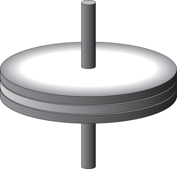
FIGURE 3-1: A capacitor creates an electric field between two charged plates separated by an insulator.
Note that because the two plates are separated by an insulator, a closed circuit isn’t formed. Nevertheless, current flows — for a moment, anyway.
How can this be? When the voltage from a source such as a battery is connected, the negative side of the battery voltage immediately begins to push negative charges toward one of the plates. Simultaneously, the positive side of the battery voltage begins to pull electrons (negative charges) away from the second plate.
What permits current to flow is the electric field that quickly builds up between the two plates. As the plate on the negative side of the circuit fills with electrons, the electric field created by those electrons begins to push electrons away from the plate on the other side of the insulator, toward the positive side of the battery voltage.
As this current flows, the negative plate of the capacitor builds up an excess of electrons, whereas the positive side develops a corresponding deficiency of electrons. Thus, voltage is developed between the two plates of the capacitor. (Remember, the definition of voltage is the difference of charge between two points.)
But there’s a catch: This current flows only for a brief time. As the electrons build up on the negative plate and are depleted from the positive plate, the voltage between the two plates increases because the difference in charge between the two plates increases. The voltage continues to increase until the capacitor voltage equals the battery voltage. Once the voltages are the same, current stops flowing through the circuit, and the capacitor is said to be charged.
At this point the magic gets even better. Once a capacitor has been charged, you can disconnect the battery from the capacitor, and the voltage will remain in the capacitor. In other words, although the voltage in the capacitor is created by the battery, this voltage isn’t dependent on the battery for its continued existence. Disconnect the battery, and the voltage remains across the two plates of the capacitor.
Thus, capacitors have the ability to store charge — an ability known as capacitance.
 Note that from a pure physics standpoint, saying that a capacitor has the ability to store charge isn’t quite accurate. What a capacitor actually stores is energy in the form of an electric field that creates a voltage across the two plates. Strictly speaking, the capacitor doesn’t have any more charge in it when it’s fully “charged” than it does when it isn’t. The difference is that when a capacitor isn’t charged, the total negative and positive charges of the capacitor are divided evenly among the plates, so there’s no voltage across the plates. In contrast, when a capacitor is charged, the negative charges are concentrated on one plate, and the positive charges are on the other plate. The total amount of charge in the capacitor is the same either way.
Here comes some more magic: If a charged capacitor is connected to a circuit, the voltage across the plates will drive current through the circuit. This is called discharging the capacitor. Just as the current that charges a capacitor lasts only for a short time, the current that results when a capacitor discharges also lasts only for a short time. As the capacitor discharges, the charge difference between the two plates decreases, and the electric field collapses. Once the two plates have reached equilibrium, the voltage across the plates reaches zero, and no current flows.
Here are a few additional things you should know about capacitors before moving on:
 The most common symbol used for capacitors in schematic diagrams is simply two parallel lines separated by a gap, as shown in the margin.
 An alternative symbol uses a straight line and a curved line to represent the plates. The curved line is generally used on the negative side of the circuit.
 Although some capacitors aren’t sensitive to polarity, many others are. This sensitivity has to do with the choice of materials used to create the capacitors: With some materials, connecting the voltage in the wrong direction can damage the capacitor. Capacitors that have distinct positive and negative terminals are called polarized capacitors. A plus sign is used in the schematic diagram to indicate the polarity, as shown in the margin.
- Sometimes capacitors are called simply caps.
-
The insulating material between the two conducting plates is properly called dielectric, a term that refers to the ability of the insulating layer to become polarized by the electric field that exists between the two plates when they become charged.
Counting Capacitance
Capacitance is the term that refers to the ability of a capacitor to store charge. It’s also the measurement used to indicate how much energy a particular capacitor can store. The more capacitance a capacitor has, the more charge it can store.
Capacitance is measured in units called farads (abbreviated F). The definition of one farad is deceptively simple. A one-farad capacitor holds a voltage across the plates of exactly one volt when it’s charged with exactly one ampere per second of current.
Note that in this definition, the “one ampere per second of current” part is really referring to the amount of charge present in the capacitor. There’s no rule that says the current has to flow for a full second. It could be one ampere for one second, or two amperes for half a second, or half an ampere for two seconds. Or it could be 100 mA for 10 seconds or 10 mA for 100 seconds.
One ampere per second corresponds to the standard unit for measuring electric charge, called the coulomb. So another way of stating the value of one farad is to say that it’s the amount of capacitance that can store one coulomb with a voltage of one volt across the plates.
It turns out that one farad is a huge amount of capacitance, simply because one coulomb is a very large amount of charge. To put it into perspective, the total charge contained in an average lightning bolt is about five coulombs, and you need only five, one-farad capacitors to store the charge contained in a lightning strike. (Some lightning strikes are much more powerful, as much as 350 coulombs.)
It’s a given that Doc Brown’s flux capacitor was in the farad range because Doc charged it with a lightning strike. But the capacitors used in electronics are charged from much more modest sources. Much more modest. In fact, the largest capacitors you’re likely to use have capacitance that is measured in millionths of a farad, called microfarads and abbreviated ![]() . And the smaller ones are measured in millionths of a microfarad, also called a picofarad and abbreviated pF.
. And the smaller ones are measured in millionths of a microfarad, also called a picofarad and abbreviated pF.
Here are a few other things you should know about capacitor measurements:
- Like resistors, capacitors aren’t manufactured to perfection. Instead, most capacitors have a margin of error, also called tolerance. In some cases, the margin of error may be as much as 80 percent. Fortunately, that degree of impression rarely has a noticeable effect on most circuits.
-
 The
The  in
in  isn’t an italic letter u; it’s the Greek letter mu, which is a common abbreviation for micro.
 - It’s common to represent values of 1,000 pF or more in
 rather than pF. For example, 1,000 pF is written as
  , and 22,000 pF is written as
  .
. -
Historical note: Like many units of measure in electronics, the farad was named after one of the all-time great pioneers of electricity, an Englishman named Michael Faraday, who did the groundbreaking research into magnetism and its relationship with electric current.
- As an example of how much Faraday and physicist James Maxwell are respected for their work, consider that Albert Einstein kept portraits of three people on the wall of his study at Princeton. They were Sir Isaac Newton, considered by many to be the greatest physicist of all time; James Maxwell, who developed the theory of electromagnetism, which is considered by many to be as great an accomplishment as Newton’s work with gravity; and Michael Faraday.
Reading Capacitor Values
If there’s enough room on the capacitor, most manufacturers print the capacitance directly on the capacitor along with other information such as the working voltage and perhaps the tolerance. However, small capacitors don’t have enough room for all that. Many capacitor manufacturers use a shorthand notation to indicate capacitance on small caps.
If you have a capacitor that has nothing other than a three-digit number printed on it, the third digit represents the number of zeros to add to the end of the first two digits. The resulting number is the capacitance in pF. For example, 101 represents 100 pF: the digits 10 followed by one additional zero.
If there are only two digits listed, the number is simply the capacitance in pF. Thus, the digits 22 indicate a 22 pF capacitor.
Table 3-1 lists how some common capacitor values are represented using this notation.
TABLE 3-1 Capacitance Markings
|
Marking |
Capacitance (pF) |
Capacitance ( |
|
101 |
100 pF |
|
|
221 |
220 pF |
|
|
471 |
470 pF |
|
|
102 |
1,000 pF |
|
|
222 |
2,200 pF |
|
|
472 |
4,700 pF |
|
|
103 |
10,000 pF |
|
|
223 |
22,000 pF |
|
|
473 |
47,000 pF |
|
|
104 |
100,000 pF |
|
|
224 |
220,000 pF |
|
|
474 |
470,000 pF |
|
|
105 |
1,000,000 pF |
|
|
225 |
2,200,000 pF |
|
|
475 |
4,700,000 pF |
|
You may also see a letter printed on the capacitor to indicate the tolerance. You can interpret the tolerance letter according to Table 3-2.
TABLE 3-2 Capacitor Tolerance Markings
|
Letter |
Tolerance |
|
A |
|
|
B |
|
|
C |
|
|
D |
|
|
E |
|
|
F |
|
|
G |
|
|
H |
|
|
J |
|
|
K |
|
|
L |
|
|
M |
|
|
N |
|
|
P |
|
|
S |
|
|
W |
|
|
X |
|
|
Z |
|
Notice that the tolerances for codes P through Z are a little odd. For codes P and W, the manufacturer promises that the capacitance will be no less than the stated value but may be as much as 100 percent or 200 percent over the stated value. For codes S, X, and Z, the actual capacitance may be as much as 20 percent below the stated value or as much as 50 percent, 40 percent, or 80 percent over the stated value. For example, if the marking is 101P, the actual capacitance is no less than 100 pF but may be as much as 200 pF. If the marking is 101Z, the capacitance is between 80 pF and 180 pF.
The Many Sizes and Shapes of Capacitors
Capacitors come in all sorts of shapes and sizes, influenced mostly by three things: the type of material used to create the plates, the type of material used for the dielectric, and the capacitance. Figure 3-2 shows some of the most common varieties of capacitors.
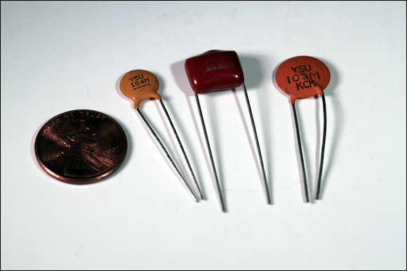
FIGURE 3-2: Capacitors are made in many different shapes and sizes.
The most common types of capacitors are
-
Ceramic disk: The plates are made by coating both sides of a small ceramic or porcelain disk with silver solder. The ceramic or porcelain disk is the dielectric, and the silver solder forms the plates. Leads are soldered to the plates, and the entire thing is dipped in resin.
Ceramic disk capacitors are small and usually have low capacitance values, ranging from 1 pF to a few microfarads. Because they’re small, their values are usually printed using the three-digit shorthand notation described earlier in this chapter, in the section “Reading Capacitor Values.”
Ceramic disk capacitors aren’t polarized, so you don’t have to worry about polarity when you use them.
-
Silver mica: The dielectric is made from mica, and this capacitor is sometimes referred to simply as a mica capacitor. As with ceramic capacitors, the plates in a silver mica capacitor are made from silver. Electrodes are joined to the plates, and then the capacitor is dipped in epoxy.
Silver mica capacitors come in about the same capacitance range as ceramic disk capacitors. However, they can be made to much higher tolerances — as close as 1 percent in some cases. Like ceramic disk capacitors, silver mica capacitors aren’t polarized.
Although ceramic disk and mica capacitors are constructed in a similar way, they’re easy to tell apart. Ceramic disk capacitors are thin, flat disks and are nearly always a dull, light-brown color. Silver mica capacitors are thicker, bulge at the ends where the leads are attached, and are shiny and sometimes colorful — red, blue, yellow, and green are common colors for silver mica capacitors. (Interestingly enough, I’ve never seen a silver mica capacitor.)
-
Film: The dielectric is made from a thin filmlike sheet of insulating material, and the plates are made from filmlike sheets of metal foil. In some cases, the plates and the dielectric are then tightly rolled together and enclosed in a metal or plastic can. In other cases, the layers are stacked and then dipped in epoxy.
Depending on the materials used, capacitance for film capacitors can be as small as 1,000 pF or as large as
 . Film capacitors aren’t polarized.
 -
Electrolytic: One of the plates is made by coating a foil film with a highly conductive, semiliquid solution called electrolyte. The other plate is another foil film on which an extremely thin layer of oxide has been deposited; this thin layer serves as the dielectric. The two layers are then rolled up and enclosed in a metal can.
 Electrolytic capacitors are polarized, so you must be sure to connect voltage to it in the proper direction. If you apply voltage in the wrong direction, the capacitor may be damaged and might even explode.
You find these two common types of electrolytic capacitors:
- Aluminum: Can be quite large, with as much as a tenth of a farad or more (
 ).
). - Tantalum: Are smaller, ranging up to about
 .
.
- Aluminum: Can be quite large, with as much as a tenth of a farad or more (
-
Variable: A capacitor whose capacitance can be adjusted by turning a knob. One common use for a variable capacitor is to tune a radio circuit to a specific frequency.
In the most common type of variable capacitor, air is used as the dielectric, and the plates are made of rigid metal. As shown in Figure 3-3, several pairs of plates are typically used in an intermeshed arrangement. One set of plates is fixed (not moveable), but the other set is attached to a rotating knob. When you turn the knob, you change the amount of surface area on the plates that overlap. This, in turn, changes the capacitance of the device.
 The schematic symbol for a variable capacitor is shown in the margin.

FIGURE 3-3: A variable capacitor.
Calculating Time Constants for Resistor/Capacitor Networks
As I mention earlier in the “What Is a Capacitor” section, when you put a voltage across a capacitor, it takes a bit of time for the capacitor to fully charge. During this time, current flows through the capacitor. Similarly, when you discharge a capacitor by placing a load across it, it takes a bit of time for the capacitor to fully discharge. Knowing exactly how much time it takes to charge a capacitor is one of the keys to using capacitors correctly in your circuits, and you can get that information by calculating the RC time constant.
Calculating the exact amount of time required to charge or discharge a capacitor requires more math than I’m willing to throw at you in this book. I don’t have any qualms about tossing up a little simple algebra, but I draw the line at calculus. Fortunately, you can skip the calculus and use just simple algebra if you’re willing to settle for close approximations rather than exactitudes. Given that most resistors and capacitors have a tolerance of plus or minus 5 or 10 percent anyway, using approximate calculations won’t have any significant effect on your circuits.
But before I tell you about making these approximate calculations, it’s important that you understand the concepts behind the calculus, even if you don’t actually do the calculus. So bear with me.
When a capacitor is charging, current flows from a voltage source through the capacitor. In most circuits, a resistor is working in series with the capacitor as well, as shown in Figure 3-4.

FIGURE 3-4: A capacitor charging circuit.
Actually, a circuit always has resistance, even if you don’t use a resistor. That’s because there’s no such thing as a perfect conductor, so even solid wire has some resistance. For the purposes of this discussion, assume that there is a resistor in the circuit, but its resistance might be ![]() .
.
The rate at which the capacitor charges through a resistor is called the RC time constant (the RC stands for resistor-capacitor), which can be calculated simply by multiplying the resistance in ohms by the capacitance in farads. Here’s the formula:
For example, suppose the resistance is ![]() and the capacitance is
and the capacitance is ![]() . Before you do the multiplication, you must first convert the
. Before you do the multiplication, you must first convert the ![]() to farads. Since one
to farads. Since one ![]() is one-millionth of a farad, you can convert
is one-millionth of a farad, you can convert ![]() to farads by dividing the
to farads by dividing the ![]() by one million. Therefore,
by one million. Therefore, ![]() is equivalent to 0.0001 F. Multiplying
is equivalent to 0.0001 F. Multiplying ![]() by 0.0001 F gives you a time constant of 1 second.
by 0.0001 F gives you a time constant of 1 second.
Note that if you want to increase the RC time constant, you can increase either the resistance or the capacitance, or both. Also note that you can use an infinite number of combinations of resistance and capacitance values to reach a desired RC time constant. For example, all the following combinations of resistance and capacitance yield a time constant of one second:
|
Resistance |
Capacitance |
RC Time Constant |
|
|
|
1 s |
|
|
|
1 s |
|
|
|
1 s |
|
|
|
1 s |
So what is the significance of the RC time constant? It turns out that in each interval of the RC time constant, the capacitor moves 63.2 percent closer to a full charge. For example, after the first interval, the capacitor voltage equals 63.2 percent of the battery voltage. So if the battery voltage is 9 V, the capacitor voltage is just under 6 V after the first interval, leaving it just over 3 V away from being fully charged.
In the second time interval, the capacitor picks up 63.2 percent, not of the full 9 V of battery voltage, but 63.2 percent of the difference between the starting charge (just under 6 V) and the battery voltage (9 V). Thus, the capacitor charge picks up just over two additional volts, bringing it up to about 8 V.
This process keeps repeating: In each time interval, the capacitor picks up 63.2 percent of the difference between its starting voltage and the total voltage. In theory, the capacitor will never be fully charged because with the passing of each RC time constant the capacitor picks up only a percentage of the remaining available charge. But within just a few time constants, the capacity becomes very close to fully charged.
The following table gives you a helpful approximation of the percentage of charge that a capacitor reaches after the first five time constants. For all practical purposes, you can consider the capacitor fully charged after five time constants have elapsed.
|
RC Time Constant Interval |
Percentage of Total Charge |
|
1 |
63.2% |
|
2 |
86.5% |
|
3 |
95.0% |
|
4 |
98.2% |
|
5 |
99.3% |
As I mentioned a moment ago, in theory a capacitor will never become fully charged. But in reality, the capacitor does eventually become fully charged. The difference between theory and reality here is that in mathematics, we can use as many digits beyond the decimal point as we want. In other words, there’s no limit to how small a number can be. But there is a limit to how small a charge can be: A charge can’t be smaller than a single electron. When enough time constants have elapsed, the difference between the battery voltage and the capacitor charge is a single electron. Once that electron joins the charge, the capacitor is full.
Combining Capacitors
In the preceding chapter, you learn that you can combine resistors in series or parallel networks to create any arbitrary resistance value you need. You can do the same with capacitors. But as you learn in the following sections, the formulas for calculating the total capacitance of a capacitor network are the reverse of the rules you follow to calculate resistor networks. In other words, the formula you use for resistors in series applies to capacitors in parallel, and the formula you use for resistors in parallel applies to capacitors in series. Isn’t it funny how science sometimes likes to mess with your mind?
Combining capacitors in parallel
Calculating the total capacitance of two or more capacitors in parallel is simple: Just add up the individual capacitor values to get the total capacitance. For example, if you combine three ![]() capacitors in parallel, the total capacitance of the circuit is
capacitors in parallel, the total capacitance of the circuit is ![]() .
.
This rule makes sense if you think about it for a moment. When you connect capacitors in parallel, you’re essentially connecting the plates of the individual capacitors. So connecting two identical capacitors in parallel essentially doubles the size of the plates, which effectively doubles the capacitance.
Figure 3-5 shows how parallel capacitors work. Here, the two circuits have identical capacitances. The first circuit accomplishes the job with one capacitors, the second does it with three. Thus, the circuits are equivalent.

FIGURE 3-5: Combining capacitors in parallel.
 Whenever you see two or more capacitors in parallel in a circuit, you can substitute a single capacitor whose value is the sum of the individual capacitors. Similarly, any time you see a single capacitor in a circuit, you can substitute two or more capacitors in parallel as long as their values add up to the original value.
The total capacitance of capacitors in parallel is always greater than the capacitance of any of the individual capacitors. That’s because each capacitor adds its own capacitance to the total.
Connecting capacitors in series
You can also combine capacitors in series to create equivalent capacitances, as shown in Figure 3-6. When you do, however, the math is a little more complicated. It turns out that the calculations required for capacitors in series are the same as calculating resistors in parallel.

FIGURE 3-6: Combing capacitors in series.
Here are the rules for calculating capacitances in series:
- If the capacitors are of equal value, you’re in luck. All you must do is divide the value of one of the individual capacitors by the number of capacitors. For example, the total capacitance of two,
 capacitors is
  .
. - If only two capacitors are involved, use this calculation:
In this formula, C1 and C2 are the values of the two capacitors.
Here’s an example, based on a
 and
and  capacitor in series:
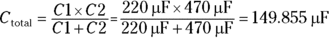
- For three or more capacitors in series, the formula is this:
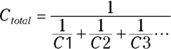
Note that the ellipsis at the end of the expression indicates that you keep adding up the reciprocals of the capacitances for as many capacitors as you have.
Here is an example for three capacitors whose values are
 ,
,  , and
, and  :
:
As you can see, the final result is
 . Unless your name happens to be Spock, you probably don’t care about the answer being so precise, so you can safely round it to an even
  .
.
Putting Capacitors to Work
Now that you know all about how capacitors work and you understand about charging, discharging, time constants, and series and parallel capacitors, you’re probably wondering what capacitors are actually used for in real-life circuits. It turns out that capacitors are incredibly useful. The following paragraphs describe the most common ways that capacitors are used:
- Storing energy: Once charged, a capacitor has the ability to store a lot of energy and discharge it when needed. One of the most familiar uses of this ability is in a camera flash. Other examples are in devices such as alarm clocks that need to stay powered up even when household power is disrupted for a few moments.
- Timing circuits: Many circuits depend on capacitors along with resistors to provide timing intervals. For example, in Chapter 6 of this minibook you learn how to use a resistor and capacitor together along with a transistor to create a circuit that flashes an LED on and off.
- Stabilizing shaky direct current: Many electronic devices run on direct current but derive their power from household AC. These devices use a power-supply circuit that converts the AC to DC. As you learn in Book 4, Chapter 2, an important part of this circuit is a capacitor that creates steady DC voltage from the constantly changing voltage of an AC circuit.
- Blocking DC while passing AC: Sometimes you need to prevent direct current from flowing while allowing alternating current to pass. A capacitor can do this. The basic trick is to choose a capacitor that will fully charge and discharge within the alternating current cycle. Remember that as the capacitor is charging and discharging, it allows current to flow. So as long as you can keep the capacitor charging and discharging, it will pass the current.
- Filtering certain frequencies: Capacitors are often used in audio or radio circuits to select certain frequencies. For example, a variable capacitor is often used in a radio circuit to tune the circuit to a certain frequency.
Charging and Discharging a Capacitor
One of the most common uses for capacitors is to store a charge that you can discharge when it’s needed. Project 13 presents a simple construction project on a solderless breadboard that demonstrates how you can use a capacitor to do this. You connect an LED to a 3 V battery power supply and use a capacitor so that when you disconnect the battery from the circuit, the LED doesn’t immediately go out. Instead, it continues to glow for a moment as the capacitor discharges.
Note that this project utilizes a small push button that can be mounted directly to your solderless breadboard. Unlike most of the other components used in this book’s projects, you can’t get this one from RadioShack. However, such buttons are available inexpensively from many online sources. Use your favorite search engine to search the web for DIP Push Button.
Figure 3-7 shows the completed project.

FIGURE 3-7: The capacitor discharge circuit.
Project 13: Charging and Discharging a Capacitor
In this project, you build a circuit that places a capacitor in parallel with an LED. When power is applied to the LED, the capacitor charges. When power is disconnected, the capacitor discharges, which causes the LED to remain lit for a short while after the power has been disconnected.
You need wire cutters and strippers to cut and strip the jumper wires.


Parts
- One solderless breadboard (RadioShack 276003)
- One 9 V battery
- One 9 V battery snap holder (RadioShack 2700325)
- One
 resistor (yellow-violet-brown)
 - One
 electrolytic capacitor (RadioShack 2721032)
 - One red LED, 5mm (RadioShack 2760209)
- One normally open DIP breadboard push button
- Three short (approximately 1-inch) 22-gauge solid jumper wires
- One 1-inch 22-gauge solid jumper wire
Steps
Throughout these steps, use the negative (–) bus strip on the left side of the board for ground and the positive (+) bus strip on the top of the board as the positive voltage.
-
Connect the battery holder.
Insert the red lead in the last hole of the left-side positive bus strip (located near hole A30) and insert the black lead in the last hole of the right-side negative bus strip (located near hole J30).
-
Mount the push button on the breadboard.
The push button should be inserted in holes E22, E20, F22, and F20.
-
Connect the resistor.
Insert the resistor into the breadboard at holes B5 and B10.
-
Insert the LED.
Insert the long lead into hole E5 and the short lead into hole F5.
Note that the circuit won’t work if you insert the LED backward. The short lead must be on the negative side of the circuit.
-
Insert the capacitor.
The negative terminal of the capacitor, marked by a series of dashes on the capacitor, should go into a hole in the right-side negative ground strip near row 10. The other lead should go in hole E10.
-
Insert the three jumper wires.
The first jumper wire should go from hole A10 to hole A20.
The second jumper wire should go from hole A22 to a nearby hole on the left-side positive bus strip.
The third jumper wire should go from hole H5 to a nearby hole on the right-side negative bus strip.
- Attach the 9 V battery to the snap connector.
-
Press the push button.
The LED lights up. If it doesn’t, make sure you’ve inserted the LED correctly.
If the LED still doesn’t light up, the push button may not be oriented correctly on the breadboard. Remove the button, rotate it 90 degrees, and reinsert it.
-
After a few seconds, release the button.
Watch how the LED goes out. Instead of turning off instantly, it fades over the course of a few seconds. That’s because when the battery is disconnected from the circuit, the capacitor discharges through the LED. As the capacitor discharges, the LED goes gradually dim and then goes out altogether.
Here are some additional points you might want to ponder or things you might want to try after you complete Project 13:
- Pull the LED out of the breadboard, and then push the button. After a few seconds, release the button. Then, use the voltmeter function of your multimeter to measure the voltage across the two leads of the capacitor. Notice that even though the battery is disconnected from the circuit, the capacitor reads 9 V.
- Try varying the size of the capacitor to see what happens. If you use a smaller capacitor, the LED extinguishes more quickly when you remove the power. If you use a larger capacitor, the LED fades more slowly.
-
You may not be able to find a capacitor larger than
 , but you can increase the capacitance by adding more capacitors in parallel with the
  capacitor.
 - Try adding a resistor in series with the capacitor. To do that, simply replace one of the jumper wires you connected in Step 6 with a resistor.
Blocking DC while Passing AC
One of the important features of capacitors is their ability to block direct current while allowing alternating current to pass. This works because of the way a capacitor allows current to flow while the plates are charging or discharging, but halts current in its tracks once the capacitor is fully charged. Thus, as long as the source voltage is constantly changing, the capacitor allows current to flow. When the source voltage is steady, the capacitor blocks current from flowing.
In Project 14, you build a simple circuit that demonstrates this principle in action. The circuit places a resistor and a light-emitting diode in series with a capacitor. Then, it uses a knife switch so that you can switch the voltage source for the current between a 9 V battery (direct current) and a 9 V AC power adapter (alternating current). Figure 3-8 shows the finished project.

FIGURE 3-8 The finished AC/DC circuit.
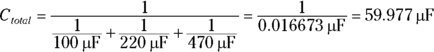
The trick to successfully building this circuit is finding a 9 V AC power adapter. If you go looking for one at your local RadioShack or at a department store, you might find one, but it will probably cost $20 or more. If you search the Internet, you can probably find one for more like $10 or $15.
Figure 3-9 shows the one I used for this project; I purchased it at a thrift store for $1. Notice the markings on the back of this power adapter:
- Input: 120 V AC 60 Hz 15 W
- Output: 9 V AC 1,000 mA
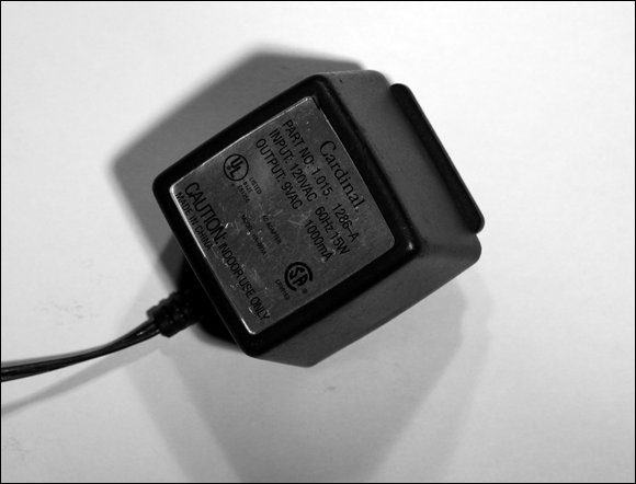
FIGURE 3-9 A 9 V AC power adapter.
These are the specifications you want to look for when you search for an AC adapter to use for this project. In particular, the output voltage must be listed at 9 V AC.
Project 14: Blocking Direct Current
In this project, you build a circuit that uses a capacitor to allow alternating current to pass but blocks direct current. The circuit simply places a capacitor in series with an LED, and then uses a DPDT switch to connect the LED/capacitor circuit to either 9 V DC or 9 V AC.

Parts
- One solderless breadboard (RadioShack 276003)
- One 9 V battery
- One 9 V battery snap holder (RadioShack 270325)
- One 9 V AC power adapter
- One
 resistor (yellow-violet-brown)
 - One
 electrolytic capacitor (RadioShack 2721032)
 - One red LED, 5mm (RadioShack 2760209)
- One DPDT knife switch (RadioShack 2751537)
- Two 3-inch 22-gauge solid jumper wires
Steps
Throughout these steps, use the negative (–) bus strip on the bottom side of the board for ground and the positive (+) bus strip on the top of the board as the positive voltage.
-
Connect the battery snap holder to the switch.
Connect the red lead to terminal 1A on the switch, and then connect the black lead to terminal 2A.
-
Connect the 9 V AC adapter to the switch.
The 9 V AC adapter should be connected to terminals 1B and 2B on the switch. The easiest way to connect the power adapter is to cut the plug off the end of the power adapter’s cable, and then strip about
 inch of insulation from the ends of the two wires that make up the cable.
 -
Connect the switch to the breadboard.
Use one of the 3-inch solid jumper wires to connect terminal 1X on the switch to the first hole in the positive bus strip on the top of the solderless breadboard. Then use the other 3-inch jumper wire to connect terminal 2X on the switch with the first hole in the ground bus strip at the bottom of the breadboard.
-
Connect the resistor.
Insert the resistor into the breadboard so that one lead is on the positive voltage bus strip (the strip that’s connected to the jumper leading to switch terminal 1X) and the other lead in hole I5.
-
Connect the LED.
Insert the short LED lead into hole E5 and the long lead into hole F5.
Note that the circuit won’t work if you insert the LED backward. The short lead must be on the negative side of the circuit.
-
Insert the capacitor.
The negative terminal of the capacitor, marked by a series of dashes on the capacitor, should go into a hole in the ground strip near row 5. The other lead should go in hole C5.
- Move the switch to the vertical position so that neither side of the switch is closed.
- Insert the 9 V battery.
-
Plug the 9 V AC power adapter into a wall outlet.
The circuit is now done and ready for testing.
-
Close the switch toward the A contacts.
This connects the 9 V battery to the circuit. The LED initially turns on, but after a few moments it begins to fade. When it goes completely out, the capacitor is fully charged. When it’s charged, the capacitor won’t allow direct current to pass, so the LED remains dark.
-
Flip the switch to the B contacts.
This action disconnects the battery from the circuit and instead connects the AC power adapter. Now the LED comes on and stays on. As long as the AC power source is applied across the circuit, the capacitor allows the current to flow, and the LED lights up.
-
Flip the switch back to the A contacts.
Because the capacitor is now fully charged, the LED goes out immediately.
-
Open the switch, and then short out the capacitor leads.
With the switch in the neutral position so that neither power source is connected to the circuit, touch both leads of the capacitor with the blade of your screwdriver. This shorts out the leads, which causes the capacitor to quickly discharge itself.
You’re done! Congratulations! You have now witnessed an important aspect of how capacitors work.