
Chapter 4
An Arduino Proximity Sensor
IN THIS CHAPTER
![]() Connecting an ultrasonic range finder to an Arduino
Connecting an ultrasonic range finder to an Arduino
![]() Displaying information on an LCD device
Displaying information on an LCD device
![]() Using new Arduino commands to work with the range finder and LCD
Using new Arduino commands to work with the range finder and LCD
![]() Building a simple proximity sensor
Building a simple proximity sensor
In this chapter, you learn how to work with two new devices that can be easily connected to an Arduino. The first is an ultrasonic range finder, which uses a short ultrasonic pulse to determine the distance to a nearby object. The second is a liquid crystal display (LCD) device that lets you display readable output from your Arduino.
Then you build a project that uses these two devices together to display the distance between the Arduino and a nearby object. Have fun!
Using an Ultrasonic Range Finder
An ultrasonic range finder is a device that determines the distance to a nearby object by bouncing ultrasonic sound waves off of the object. In short, the range finder emits a short burst of ultrasonic sound (that is, sound in a frequency range that cannot be heard by humans) and then listens for the sound reflected off the object. The amount of time that elapses between the initial burst and the detected reflection can be used to determine how far away the object is from the detector.
Looking at the HC-SR04 Range Finder
Figure 4-1 shows a commonly used ultrasonic range finder called an HC-SR04. You can purchase this range finder online for just a few dollars from a variety of online retailers, including Amazon (www.amazon.com) and Newegg (www.newegg.com).
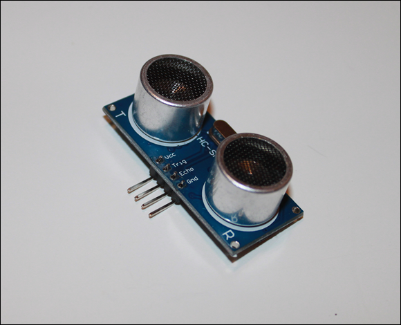
FIGURE 4-1: An HC-SR04 Range Finder.
The HC-SR04 is built on a small circuit board (approximately 2 inches long and ![]() inch tall) with a four-pin connector that can easily attach to a breadboard. The HC-SR04 includes a transmitter that can generate ultrasonic sounds, a receiver that can listen for ultrasonic sounds, and circuitry that measures how much time elapses between transmission of a sound pulse and the reception of the sound’s echo.
inch tall) with a four-pin connector that can easily attach to a breadboard. The HC-SR04 includes a transmitter that can generate ultrasonic sounds, a receiver that can listen for ultrasonic sounds, and circuitry that measures how much time elapses between transmission of a sound pulse and the reception of the sound’s echo.
Table 4-1 defines the four pins on the HC-SR04.
TABLE 4-1 Pinouts for the HC-SR04 Ultrasonic Range Finder
|
Pin |
Name |
Function |
|
1 |
VCC |
|
|
2 |
TRIG |
Triggers the generation of an ultrasonic pulse to measure the distance to a nearby object |
|
3 |
ECHO |
Following a trigger pulse, generates an echo pulse whose duration represents the distance to the object |
|
4 |
GND |
Ground |
To connect the HC-SR04 to an Arduino, first connect pins 1 and 4 to power and ground, respectively. Then, connect pins 2 and 3 to any of the Arduino’s digital I/O pins.
After the HC-SR04 is connected to the Arduino, you can initiate a range check by sending a short HIGH pulse to the TRIG pin. This causes the HC-SR04 to emit a short ultrasonic pulse over its transmitter and then listen for the echo on its receiver. When the echo has been received, the HR-SR04 sends a pulse over its ECHO pin. The duration of this pulse is the same as the amount of time it took for the ultrasonic echo to be received.
You can then use the duration of the ECHO pulse to determine the distance to the object that reflected the ultrasonic sound pulse. You’ll have to do a little math, but nothing too complicated.
In the next few sections, I show you how to generate a trigger pulse for an HC-SR04, how to read the length of the echo pulse, and how to calculate the distance to the object based on the echo pulse length.
Generating a trigger pulse
The HC-SR04 requires a short pulse on its TRIG pin to initiate the range-finding process. This pulse must be at least 10 microseconds, but it’s typically 100 microseconds.
To generate a pulse on an Arduino digital I/O pin, you simply set the output pin to HIGH, delay for the desired length of the pulse, and then set the pin to LOW. Unfortunately, the delay function (see Chapter 1 of this minibook) works in milliseconds (thousands of a second) rather than in microseconds (millionths of a second). You need to use the delayMicroseconds function to create a delay shorter than 1 millisecond.
Here’s a complete bit of code that generates a 100-microsecond pulse on pin 9:
digitalWrite(9, LOW);
delayMicroseconds(20);
digitalWrite(9, HIGH);
delayMicroseconds(100);
digitalWrite(9, LOW);
This code begins by setting the output pin to LOW and waiting for 20 microseconds. This action gives the pulse a clean start. Then pin 9 is set to HIGH for 100 microseconds before it’s returned to LOW.
Assuming that pin 9 is connected to the TRIG pin of the HC-SR04, this code will initiate the range check.
Reading pulse input
The Arduino programming library includes a function called pulseIn, which reads an input pulse on a digital input pin and returns the duration of the pulse as an integer. The pulseIn function accepts two arguments. The first argument indicates the pin to read (which must be previously configured as an input pin). The second argument indicates whether you want to listen for a HIGH or LOW pulse.
An optional third argument specifies a time-out value; if a pulse hasn’t been received before the time-out value elapses, the pulseIn function returns 0.
The pulseIn function waits for the pulse to begin, and begins counting microseconds until the pulse ends. It then returns the counted length of the pulse.
Here’s an example of how you can use it, assuming that pin 8 is connected to the ECHO pin on the HC-SR04:
int duration;
pinMode(8, INPUT); // ECHO pin
pinMode(9, OUTPUT); // TRIG pin
// Trigger the HC-SR04
digitalWrite(9, LOW);
delayMicroseconds(20);
digitalWrite(9, HIGH);
delayMicroseconds(100);
digitalWrite(9, LOW);
// Read the ECHO pulse
duration = pulseIn(8, HIGH)
The preceding code starts by setting the I/O mode for the TRIG and ECHO pins. It then sends a 100-microsecond trigger pulse to the TRIG pin, and then reads the echo pulse on the ECHO pin. When this code completes, the duration variable will contain the length of the echo pulse in microseconds.
Doing the math
When you’ve obtained the length of the echo pulse from the HC-SR04, you can use the result to calculate the distance to the object that reflected the range finder’s ultrasonic sound.
You first need to decide what unit of measure you want to use. For this chapter, measure the distance in centimeters. You could work in inches and feet, but the math will be much simpler if you work in centimeters.
To convert the duration of the echo pulse to a distance in centimeters, you need to know a key fact: It takes 29.387 microseconds for a sound wave to travel one centimeter. Thus, you can determine the distance that the ultrasonic wave traveled by dividing the length of the pulse received from the HC-SR04 by 29.387.
However, you’re not interested in the total distance that the ultrasonic sound wave traveled; you want to know the distance from the range finder to the object that reflected the sound. The sound wave travels that distance twice: once on the way to the object, and then again as it bounces back to the range finder. Thus, you must divide the total distance traveled by 2 to get the distance to the object.
Rather than divide the duration by 29.387 and then divide it again by 2, you can achieve the same result by dividing the pulse length by twice 29.387, which is 58.774.
So here’s what the math looks like, once you’ve read the pulse duration into the pulseLength variable:
distance = pulseLength / 58.774;
The preceding statement will save the distance in centimeters to the object in distance.
Before you put all of this together into a single program, I want to direct your attention to the second major component of this chapter’s range finder project, the LCD that you’ll use to display the distance detected by the range finder.
Using an LCD
Many different types of display devices are available for Arduino projects. Figure 4-2 shows that one of the most common types is a small LCD that can display two lines of 16 characters, controlled by a popular LCD controller called the Hitachi HD44780. You can purchase one of these displays for just a few dollars from online retailers such as Amazon (www.amazon.com) or Newegg (www.newegg.com).
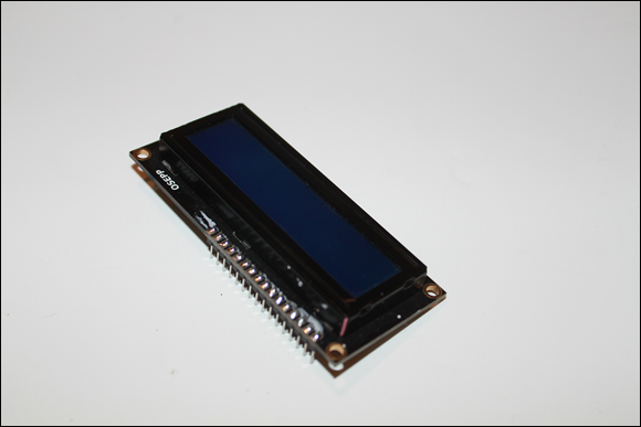
FIGURE 4-2: A typical 2 x 16 LCD.
In this section, I show you how to connect this type of LCD to an Arduino board and how use the LCD in your Arduino sketches.
Connecting an LCD to Arduino
An HD44780-type LCD includes a 16-pin connection that you can plug directly into a breadboard. Table 4-2 lists the name and function of each of the 16 pins in the LCD’s interface.
TABLE 4-2 Pinouts for an HD44780-Type LCD
|
Pin |
Name |
Function |
|
1 |
GND |
Ground. |
|
2 |
VSS |
|
|
3 |
VO |
Controls the contrast on the display. Typically connected to the center pole of a potentiometer. |
|
4 |
RS |
Used to indicate whether data or a command is being sent to the device. |
|
5 |
RW |
Read/write, almost always connect to ground. |
|
6 |
CLOCK |
Also called Enable or just E. Used to trigger a read of the data pins. |
|
7 |
D0 |
Data bit 0. (Not used in four-bit mode.) |
|
8 |
D1 |
Data bit 1. (Not used in four-bit mode.) |
|
9 |
D2 |
Data bit 2. (Not used in four-bit mode.) |
|
10 |
D3 |
Data bit 3. (Not used in four-bit mode.) |
|
11 |
D4 |
Data bit 4. |
|
12 |
D5 |
Data bit 5. |
|
13 |
D6 |
Data bit 6. |
|
14 |
D7 |
Data bit 7. |
|
15 |
LED+ |
Backlight |
|
16 |
LED- |
Backlight ground. |
The LCD module can operate in two basic modes:
- 8-bit: In 8-bit mode, all eight of the data bit pins are used to send a single byte of data to the LCD. This mode is efficient and simple to use, but it requires that you connect all eight of these data pins to digital I/O pins on the Arduino, leaving only a few pins available for other purposes.
- 4-bit: In 4-bit mode, only four of the data bit pins are used (pins 11 through 14) to send each byte. Because each byte of data requires eight bits, it takes two reads of the four data bits to send a complete byte. This complicates the programming but reduces the number of Arduino pins that must be used.
Fortunately, the complications of using the LCD in 4-bit mode are not your problem. The Arduino comes with a special library of functions that handle all those complexities. As a result, you’ll almost always use the LCD in 4-bit mode.
In addition to the four data bits, two additional pins must be connected to Arduino digital I/O pins: the RS pin (pin 4) and the CLOCK pin (pin 6). Once again, the LCD programming library takes care of all the details of using these pins properly to display data on the LCD, so you don’t need to worry about the details of how these pins work.
Pins 1 and 2 must be connected to ground and ![]() , respectively, to provide basic power for the LCD, and pins 15 and 16 are also usually connected to power and ground, respectively, to energize the backlight, which makes the LCD easier to read.
, respectively, to provide basic power for the LCD, and pins 15 and 16 are also usually connected to power and ground, respectively, to energize the backlight, which makes the LCD easier to read.
Pin 3 is also commonly used to adjust the contrast of the display. You’ll generally connect this pin to the center pole of a potentiometer (![]() or so is usually appropriate), with the outside poles of the pot connected to
or so is usually appropriate), with the outside poles of the pot connected to ![]() and ground.
and ground.
Programming the LCD
Arduino provides an entire library of functions designed to work directly with an HD44780 LCD. Table 4-3 lists a few of the functions that are available in this library. (For a complete list, go to www.arduino.cc/en/Reference/LiquidCrystal).
TABLE 4-3 Pinouts for an HD44780-Type LCD
|
Function |
Function |
|
LiquidCrystal() |
Creates a variable of type LiquidCrystal, which you can then use to call other functions. The arguments passed to this function specify the Arduino pins that are used for the various LCD features. |
|
begin() |
Must be called to initialize the LCD before any information can be written to it. The arguments indicate how many columns and rows of characters can be displayed on the LCD. |
|
clear() |
Erases the LCD. |
|
home() |
Moves the cursor to the top left of the display. |
|
setCursor() |
Moves the cursor to a particular row and column position. |
|
print() |
Displays text on the LCD. |
In order to use any of the functions listed in Table 4-3, your program must include the following statement:
#include LiquidCrystal
This statement is required to make the functions of the LiquidCrystal library available to your program.
Next, your program should create a variable of type LiquidCrystal. Creating a variable of a library type is similar to creating a variable of a built-in type such as int or float, except that you can provide arguments in the variable declaration. In the case of the LiquidCrystal data type, you provide a total of six arguments, representing the digital I/O pins that will be used for the RS, ENABLE, D0, D1, D2, and D3 pins. For example:
LiquidCrystal lcd(12, 11, 5, 4, 3, 2);
In this example, the variable will be named lcd; pins 12 and 11 will be used for RS and ENABLE; and pins 5, 4, 3, and 2 will be used for the data pins.
After you’ve assigned the digital I/O pins to the LCD, you don’t need to directly access those pins within your program. Instead, the other LiquidCrystal library functions will use those pins to control the LCD.
Having created an lcd variable, the next step is to initialize it using the begin function, like this:
lcd.begin(16, 2);
Here, the LCD is initialized for a display of two rows of 16 characters each.
You can then print data to the LCD, like this:
lcd.print("Hello, World!");
Here, the text “Hello, World!” is displayed on the LCD.
In some cases, you’ll want to control exactly where text should be displayed. To do that, you can use the setCursor function, followed by a print function. For example, if you want to display the text “Hello, World!” beginning in column 5 of the second row, use this code:
lcd.setCursor(4, 1);
lcd.print("Hello, World!");
Note that both rows and columns are numbered starting with 0, not 1. So the fifth column is column 4, and the second row is row 1.
Finally, you may need to erase the entire contents of the LCD. To do that, use the clear function:
lcd.clear();
Here, the entire LCD screen is erased.
Now that I’ve explained the details of connecting an LCD to an Arduino board and controlling it from a sketch, let’s look at a project that combines a range finder with an LCD board to display the distance from a nearby object and light an LED if the object gets too close.
Building a Proximity Sensor
In this section, you build a simple proximity sensor that uses an HC-SR04 ultrasonic range finder and an HD44780-compatible LCD. The ultrasonic range finder is used to track the distance to nearby objects; that distance is displayed on the LCD. If an object gets closer than 10 centimeters, an LED lights up to indicate that an object is close by.
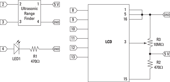
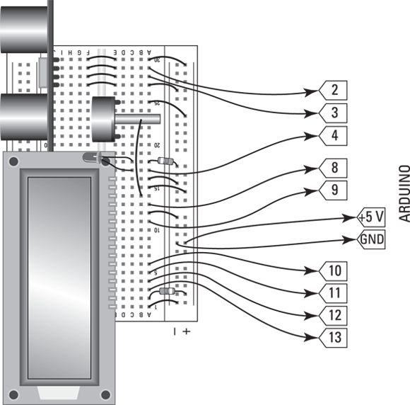
Figure 4-3 shows the schematic diagram for this project, and Figure 4-4 shows the assembled project. The details for building the project are shown in Project 47, and the complete program to run the project is shown in Listing 4-1. Have fun!

FIGURE 4-3: Schematic diagram for the Arduino proximity sensor (Project 47).
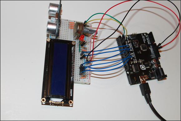
FIGURE 4-4: The assembled Arduino proximity sensor (Project 47).
Project 47: An Arduino Proximity Sensor
In this project, you build a proximity sensor that displays the distance to a nearby object on an LCD panel and flashes an LED when the object is closer than 10cm.

Parts
- One computer with Arduino IDE installed
- One Arduino UNO board
- One mini-B USB cable
- One small solderless breadboard (RadioShack 2760003)
- One 5mm red LED (RadioShack 2760209)
- One HC-SR04-type Ultrasonic Range Finder
- One HD44780-compatible 16 x 2 LCD
- Two
 resistors (yellow-violet-brown)
 - One
 potentiometer
 - 22 jumper wires
Steps
-
Insert the LCD.
Orient the LCD so that pin 1 is inserted into E16 and pin 16 is inserted into E1. Orient the LCD so that it lays over the top of the center gap of the breadboard. It will overhang the top of the breadboard by about
 inches.
 -
Insert the Ultrasonic Range Finder.
Orient the range finder so that pin 1 (Vcc) is inserted into J30 and pin 4 (Gnd) is inserted into J27. The transmitter and receiver of the range finder should face away from the breadboard.
-
Insert the potentiometer.
Orient the potentiometer so that the center pin is inserted into D23 and the other two pins are inserted into D21 and D25. The knob of the potentiometer should face toward column A.
-
Insert the resistors.
 : A18 to ground
 : A2 to the positive bus
 -
Insert the LED.
Anode: C17
Cathode: C18
-
Insert the jumpers.
A1: Ground
A12: Ground
A15: Positive bus
A16: Ground
A21: Ground
A25: Positive bus
A27: Ground
A30: Positive bus
E27: F27
E28: F28
E29: F29
E30: F30
- Connect jumpers from the breadboard to the digital pins on the UNO board.
Breadboard
Digital Pin
A3
13
A4
12
A5
11
A6
10
A11
9
A13
8
A18
4
A28
3
A29
2
-
Connect the ground bus to the UNO board ground.
Use a jumper to connect any convenient hole in the ground bus on the breadboard to either of the GND pins on the UNO board.
-
Connect the positive bus to the UNO board
 .
.Use a jumper to connect any convenient hole in the ground bus on the breadboard to the 5 V pin on the UNO board.
-
Connect the UNO to the computer.
Use the mini-B USB connector.
-
Upload the Proximity Sensor program (see Listing 4-1) to the UNO.
The LCD will display the distance of the nearest object. When the distance is less than 10cm, the LED will flash.
LISTING 4-1 The Proximity Sensor (Project 47)
// Proximity Sensor
// Doug Lowe
// September 18, 2016
// This program uses an HC-SR04 Ultrasonic Range
// Detector and an HD44780-compatible LCD to detect and
// display proximity of nearby objects. The distance to
// the object is displayed on the LCD and updated every
// 0.5 seconds. If the object is closer than 10cm, an LED
// flashes.
//
// Arduino Digital Pin Connections:
//
// 2 - Ultrasonic Trigger
// 3 - Ultrasonic Echo
// 4 - LED
// 8 - LCD RS
// 9 - LCD Clock
// 10 - LCD D0
// 11 - LCD D1
// 12 - LCD D2
// 13 - LCD D3
#include <LiquidCrystal.h>
// Create the LCD and assign the interface pins
LiquidCrystal lcd(8, 9, 10, 11, 12, 13);
int close = 10; // The distance that triggers the LED
void setup() {
// Initialize the LCD and display the headings
lcd.begin(16, 2);
lcd.print("Proximity Sensor");
lcd.setCursor(0, 1);
lcd.print("Range: ");
// Set the pin modes
pinMode(2,OUTPUT); // Trigger pin
pinMode(3, INPUT); // Echo pin
pinMode(4, OUTPUT); // LED pin
}
void loop() {
float distance;
int pulseLength;
// Send the trigger pulse to start the echo ranging
digitalWrite(2, LOW);
delayMicroseconds(20);
digitalWrite(2, HIGH);
delayMicroseconds(100);
digitalWrite(2, LOW);
// Get the echo pulse and calculate the distance
pulseLength = pulseIn(3, HIGH);
distance=pulseLength / 58.774;
// Show the distance and erase the rest of the line
lcd.setCursor(7,1);
lcd.print(distance);
lcd.print(" ");
// Flash the LED if the object is close
If (distance < close)
{
digitalWrite(4, HIGH);
delay(50);
digitalWrite(4, LOW);
delay(50);
}
else
{
delay(100);
}
}