
Chapter 1
Working with Basic Circuits
IN THIS CHAPTER
![]() Examining the basic elements of circuits
Examining the basic elements of circuits
![]() Looking at different batteries that you can use to power your circuits
Looking at different batteries that you can use to power your circuits
![]() Categorizing the various switches that you can use to control your circuits
Categorizing the various switches that you can use to control your circuits
![]() Learning the difference between series and parallel circuits
Learning the difference between series and parallel circuits
![]() Building a variety of circuits to demonstrate basic circuits
Building a variety of circuits to demonstrate basic circuits
Book 1 introduces you to the underlying concepts of electricity and gives you an overview of the tools and skills you need to start working with electronics. Now that you know what electricity is, and you’ve gone shopping for some basic tools (such as a solderless breadboard, a soldering iron, and a multimeter), it’s time to start learning how electronic circuits work.
This chapter explores the basic concepts of a circuit. The circuits I cover in this chapter are very simple, consisting of nothing other than batteries that supply voltage, wires that carry current, and lamps that consume power (because they light up in the process!). I also throw in some switches that let you turn the circuit on and off.
Though simple, the circuits presented here are a great introduction to more complicated circuits. The remaining chapters in this minibook add additional elements that are basic to all circuits, such as resistors, capacitors, coils, diodes, transistors, and integrated circuits. By the time you get through this minibook, you’ll be familiar with all the basic components of electronic circuits.
What Is a Circuit?
A circuit is a complete course of conductors through which current can travel. Circuits provide a path for current to flow. To be a circuit, this path must start and end at the same point. In other words, a circuit must form a loop.
For example, Figure 1-1 shows a simple circuit that includes two components: a battery and a lamp. The circuit allows current to flow from the battery to the lamp, through the lamp, then back to the battery. Thus, the circuit forms a complete loop.

FIGURE 1-1: A simple circuit.
Of course, circuits can be more complex. However, all circuits can be distilled down to three basic elements:
- Voltage source: A voltage source causes current to flow. In Figure 1-1, the voltage source is the battery.
-
Load: The load consumes power; it represents the actual work done by the circuit. Without the load, there’s not much point in having a circuit.
In Figure 1-1, the load is the lamp. In complex circuits, the load is a combination of components, such as resistors, capacitors, transistors, and so on.
-
Conductive path: The conductive path provides a route through which current flows. This route begins at the voltage source, travels through the load, and then returns to the voltage source. This path must form a loop from the negative side of the voltage source to the positive side of the voltage source.
In Figure 1-1, the two lines that travel between the battery and the lamp represent the conductive path. The conductive path can be intricate in a complex circuit, but it must still form a loop from the negative side of the voltage source to the positive side.
The following paragraphs describe a few additional interesting points to keep in mind as you ponder the nature of basic circuits:
-
When a circuit is complete and forms a loop that allows current to flow, the circuit is called a closed circuit. If any part of the circuit is disconnected or disrupted so that a loop is not formed, current cannot flow. In that case, the circuit is called an open circuit.
 Open circuit is an oxymoron. After all, the components must form a complete path to be considered a circuit. If the path is open, it isn’t a circuit. Therefore, open circuit is most often used to describe a circuit that has become broken, either on purpose (by the use of a switch, which I discuss later in this chapter) or by some error, such as a loose connection or a damaged component.
 -
Short circuit refers to a circuit that does not have a load. For example, Figure 1-2 shows a short circuit; the lamp is connected to the circuit but a direct connection is present between the battery’s negative terminal and its positive terminal, too.
 Current in a short circuit can flow at dangerously high levels. Short circuits can damage electronic components, cause a battery to explode, or maybe start a fire. The short circuit shown in Figure 1-2 illustrates an important point about electrical circuits: It is possible — common, even — for a circuit to have multiple pathways for current to flow. In Figure 1-2, the current can flow through the lamp as well as through the path that connects the two battery terminals directly.
Current flows everywhere it can. If your circuit has two pathways through which current can flow, the current doesn’t choose one over the other; it chooses both. However, not all paths are equal, so current doesn’t flow equally through all paths. In the circuit shown in Figure 1-2, current will flow much more easily through the short circuit than it will through the lamp. Thus, the lamp will not glow because nearly all the current will bypass the lamp in favor of the easier route through the short circuit. Although a small amount of current will flow through the lamp, the current flowing through the lamp will not be sufficient to cause the lamp to visibly glow.
To determine how much current flows through a given path, you use a mathematical formula that is explained in Chapter 2 of this minibook. Nevertheless, when one of the available paths is a short circuit, you needn’t bother with the formula because nearly all the current will flow through the short circuit.
-
You can imagine electric current flowing through a circuit from the positive side of the voltage source to the negative side because this is usually how you visualize a circuit when you study it. For example, in Figure 1-1, you can think of the current as flowing in a clockwise direction, starting at the positive terminal of the battery, flowing through the path at the left side of the diagram to the lamp at the top of the diagram, through the lamp and then through the path at the right side of the diagram and finally returning to the negative terminal of the battery.
As you see in Book 1, Chapter 2, this way of thinking about current flow is called conventional current. In reality, the electric charge — and the electrons — in the circuit flow from the negative side of the voltage source through the circuit to the positive side of the voltage source.

FIGURE 1-2: A short circuit.
Using Batteries
The easiest way to provide a voltage source for a circuit is to include a battery. There are plenty of other ways to provide voltage, including AC adapters (which you can plug into the wall) and solar cells (which convert sunlight to voltage). However, batteries remain the most practical source of juice for most of the circuits you build in this book.
A battery is a device that converts chemical energy into electrical energy in the form of voltage, which in turn can cause current to flow. A battery works by immersing two plates made of different metals into a special chemical solution called an electrolyte. The metals react with the electrolyte to produce a flow of charges that accumulate on the negative plate, called the anode. The positive plate, called the cathode, is sucked dry of charges. As a result, a voltage is formed between the two plates. These plates are connected to external terminals to which you can connect a circuit to cause current to flow.
Figure 1-3 shows a simplified diagram of how a battery works. A bowl filled with the right kind of chemical plus an anode and a cathode made of the right kind of metal gives you a working battery.
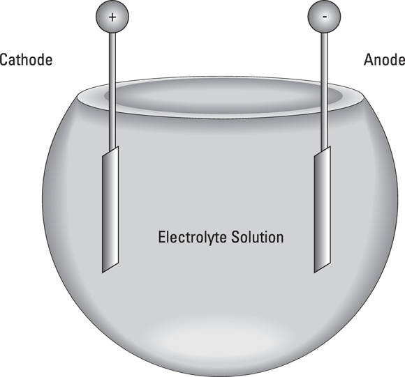
FIGURE 1-3: What goes on inside a battery.
 Technically, Figure 1-3 shows a cell, not a battery. A battery is a combination of two or more cells.
Batteries come in many different shapes and sizes, but for the purposes of this book, you need concern yourself only with a few standard types of batteries, all of which are available at any grocery, drug, or department store. Figure 1-4 shows the most common sizes available.

FIGURE 1-4: Common batteries.
Cylindrical batteries come in four standard sizes: AAA, AA, C, and D. Regardless of the size, these batteries provide 1.5 V each; the only difference between the smaller and larger sizes is that the larger batteries can provide more current. Technically, AAA, AA, C, and D cells are just that — single cells, not batteries. But if it were a crime to call them batteries, our prisons would be more overloaded than they already are.
The cathode, or positive terminal, in a cylindrical battery is the end with the metal bump. The flat metal end is the anode, or negative terminal.
The rectangular battery in Figure 1-4 is a 9 V battery. It truly is a battery because that little rectangular box actually contains six small cells, each about half the size of a AAA cell. The 1.5 volts produced by each of these small cells combine to create a total of 9 volts.
Here are a few other things you should know about batteries:
- Besides AAA, AA, C, D, and 9 V batteries, many other battery sizes are available. Most of those batteries are designed for special applications, such as digital cameras, hearing aids, laptop computers, and so on.
-
All batteries contain chemicals that are toxic to you and to the environment. Treat them with care, and dispose of them properly according to your local laws. Don’t just throw them in the trash.
- You can (and should) use your multimeter to measure the voltage produced by your batteries. Set the multimeter to an appropriate DC voltage range (such as 20 V). Then, touch the red test lead to the positive terminal of the battery and the black test lead to the negative terminal. The multimeter will tell you the voltage difference between the negative and positive terminals. For cylindrical batteries (AAA, AA, C, or D) it should be about 1.5 V. For 9 V batteries, it should be about 9 V.
- Rechargeable batteries cost more than non-rechargeable batteries but last longer because you can recharge them when they go dead.
-
The technical term for a cell that cannot be recharged is primary cell. A rechargeable cell is properly called a secondary cell. However, I would be shocked if you walked into any store that sells batteries and asked for secondary cells and the salesperson knew what you were talking about.
-
The easiest way to use batteries in an electronic circuit is to use a battery holder, which is a little plastic gadget designed to hold one or more batteries.
- Wonder why they sell AAA, AA, C, and D cells but not A or B? Actually, A cell and B cell batteries do exist. However, those sizes never really caught on in consumer devices, so they aren’t readily available at retail stores.
Building a Lamp Circuit
Project 1 shows you how to build a simple circuit that uses a battery to light a lamp. Although this circuit is quite simple, it helps illustrate the basic principles I’ve explained so far. Figure 1-5 shows the circuit assembled.
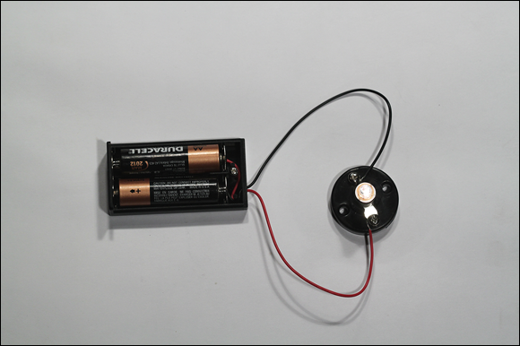
FIGURE 1-5: A simple lamp circuit.
Project 1: A Simple Lamp Circuit
In this project, you build a simple circuit that connects a lamp to a battery. You also use a multimeter to measure the voltage and current in the circuit. To assemble and test the circuit, you need a small Phillips-head screwdriver and a multimeter.
Parts
- Two AA batteries
- One battery holder (RadioShack 2700408)
- One lamp holder (RadioShack 2720357)
- One 2.33 V flashlight lamp (RadioShack 2721175)

Steps
-
Attach the red lead from the battery holder to one of the screw terminals on the lamp holder.
Loosen the screw terminal a bit to create a gap under the screw. Next, bend the stripped end of the red lead into a hook shape (you can do this easily by wrapping the wire around the tip of the screwdriver). Insert the stripped end of the lead beneath the terminal screw, and then tighten the screw to secure the wire.
- Attach the black lead to the other terminal on the lamp holder.
- Insert the lamp into the lamp holder.
-
Insert the batteries into the holder.
The lamp should light.
-
Set the multimeter range to the lowest DC voltage setting that will measure at least 3 volts.
My meter has a 5 V DC range, so I used that setting.
-
Touch the red multimeter lead to the lamp holder terminal that the red battery holder lead is attached to, and then touch the black lead to the other terminal.
The meter should read about 3 volts.
-
Disconnect the red battery lead from the lamp holder.
This breaks the circuit, so the lamp will go out.
-
Turn the multimeter dial to your highest DC mA setting.
On mine, the highest setting is 1,000 DC mA.
-
Touch the stripped end of the red battery lead to the tip of the red multimeter lead, and then touch the tip of the black multimeter lead to the unconnected terminal on the lamp holder.
The meter should read approximately 250 mA. If the largest DC mA range on your multimeter is less than 250 mA, you may not get an accurate reading. However, you should get an indication that the current exceeds the maximum for the range.
Additionally, when you test the current, the lamp comes back on because the meter completes the circuit.
Working with Switches
Switches are an important part of most electronic circuits. In the simplest case, most circuits contain an on/off switch to turn the circuit on and off. In addition to the on/off switch, many circuits contain additional switches that control how the circuit works or activate different features of the circuit.
Switches are mechanical devices with two or more leads (or terminals) that are internally connected to metal contacts which can be opened or closed by the person operating the switch. When the switch is in the On position, the contacts are brought together to complete the circuit so that current can flow. When the contacts are together, the switch is closed. When the contacts are apart, the switch is open and current cannot flow.
The following sections describe two ways to categorize switches: by the method used to operate the switch and by the connections made by the switch.
The many ways to throw the switch
One way to categorize switches is by the movement a person uses to open or close the contacts. Figure 1-6 shows many different switch designs. The most common are
- Slide switch: A slide switch has a knob that you can slide back and forth to open or close the contacts.
- Toggle switch: A toggle switch has a lever that you flip up or down to open or close the contacts. Common household light switches are examples of toggle switches.
- Rotary switch: A rotary switch has a knob that you turn to open and close the contacts. The switch in the base of many tabletop lamps is an example of a rotary switch.
- Rocker switch: A rocker switch has a seesaw action. You press one side of the switch down to close the contacts, and press the other side down to open the contacts.
- Knife switch: A knife switch is the kind of switch Igor throws in a Frankenstein movie to reanimate the creature. In a knife switch, the contacts are exposed for everyone to see.
-
Push-button switch: A push-button switch is a switch that has a knob that you push to open or close the contacts. In some push-button switches, you push the switch once to open the contacts and then push again to close the contacts. In other words, each time you push the switch, the contacts alternate between opened and closed.
Other pushbutton switches are momentary contact switches, where contacts change from their default state only when the button is pressed and held down. The two types of momentary contact switches are
- Normally open (NO): In a normally open switch, the default state of the contacts is open. When you push the button, the contacts are closed. When you release the button, the contacts open again. Thus, current flows only when you press and hold the button.
- Normally closed (NC): In a normally closed switch, the default state of the contacts is closed. Thus, current flows until you press the button. When you press the button, the contacts are opened and current does not flow. When you release the button, the contacts close again and current resumes.
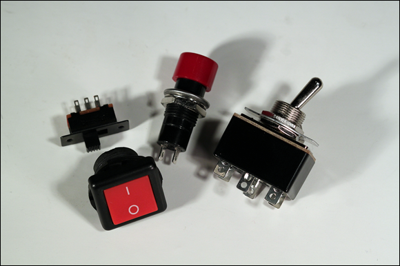
FIGURE 1-6: There are switches for every need.
Making connections with poles and throws
Another way to classify switches is by the connections they make. If you were under the impression that switches simply turn circuits on and off, guess again. Two important factors that determine what types of connections a switch makes are
-
Poles: A switch pole refers to the number of separate circuits that the switch controls. A single-pole switch controls just one circuit. A double-pole switch controls two separate circuits.
A double-pole switch is like two separate single-pole switches that are mechanically operated by the same lever, knob, or button.
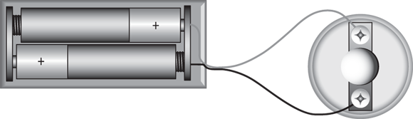
- Throw: The number of throws indicates how many different output connections each switch pole can connect its input to. Figure 1-7 shows the two most common types, single-throw and double-throw:
- A single-throw switch is a simple on/off switch that connects or disconnects two terminals. When the switch is closed, the two terminals are connected and current flows between them. When the switch is opened, the terminals are not connected, so current does not flow.
- A double-throw switch connects an input terminal to one of two output terminals. Thus, a double-pole switch has three terminals. One of the terminals is called the common terminal. The other two terminals are often referred to as A and B. When the switch is in one position, the common terminal is connected to the A terminal, so current flows from the common terminal to the A terminal but no current flows to the B terminal. When the switch is moved to its other position, the terminal connections are reversed: Current flows from the common terminal to the B terminal, but no current flows through the A terminal.

FIGURE 1-7: Single- and double-throw switches.
Switches vary in both the number of poles and the number of throws. In theory, any number of poles and any number of throws is possible. However, most switches have one or two poles and one or two throws. This leads to four common combinations, as described in the following paragraphs. The symbols used in schematic diagrams for each of these switches are shown in the margins.
 SPST (single pole, single throw): A basic on/off switch that turns a single circuit on or off. An SPST switch has two terminals: one for the input and one for the output.
 SPDT (single pole, double throw): An SPDT switch routes one input circuit to one of two output circuits. This type of switch is sometimes called an A/B switch because it lets you choose between two circuits, called A and B. An SPDT switch has three terminals: one for the input and two for the A and B outputs.
 DPST (double pole, single throw): A DPST switch turns two circuits on or off. A DPST switch has four terminals: two inputs and two outputs.
 DPDT (double pole, double throw): A DPDT switch routes two separate circuits, connecting each of two inputs to one of two outputs. A DPDT switch has six terminals: two for the inputs, two for the A outputs, and two for the B outputs.
Here are a few other points to ponder concerning the arrangement of poles and throws:
- Switches with more than two poles or more than two throws are not commonplace, but they do exist. Rotary switches lend themselves especially well to having many throws. For example, the rotary switch in a multimeter typically has 16 or more throws, one for each range of measurement the meter can make.
- A common variation of a double-throw switch is to have a middle position that does not connect to either output. Often called center open, this type of switch has three positions, but only two throws. For example, an SPDT center open switch can switch one input between either of two outputs, but in its center position, neither output is connected.
-
If you’re stocking up on switches just to have them on hand, you’re better off buying DPDT switches rather than single-pole or single-throw switches because a DPDT can be used when a circuit calls for a simpler SPST, SPDT, or DPST switch. You can use a DPDT switch when a simpler type is called for because there’s no law that says you have to wire all the contacts on the switch. For example, to use a DPDT switch as an SPST switch, you just use one of the poles and one of the throws and leave the other connections unused.
Building a Switched Lamp Circuit
Project 2 presents a simple construction project that lets you explore the use of a simple on/off switch to control a lamp. Figure 1-8 shows the assembled project.
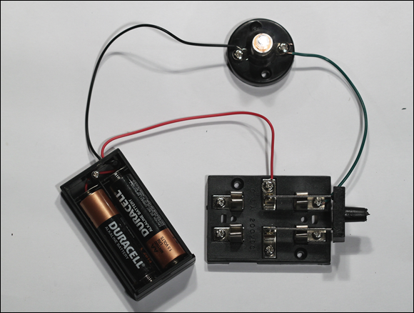
FIGURE 1-8: The switched lamp project.
This project and the remaining projects in this chapter use a DPDT knife switch from RadioShack, pictured in Figure 1-9. It’s unlikely that you’d use a knife switch in an actual electronic circuit. However, a knife switch like this is a perfect tool for learning the ins and outs of working with switches. For one thing, it is entirely exposed, so you can see how it works. Additionally, because they come on their own base and have screw terminals, connecting them in temporary circuits is simple because you don’t have to do any soldering.

FIGURE 1-9: The DPDT knife switch.
As you can see in the figure, the knife switch is a double pole, double throw (DPDT) switch, which means it operates like two SPDT switches that are mechanically linked. I numbered the six terminals on the switch 1X, 1A, 1B, 2X, 2A, and 2B. The 1 and 2 designate which of the two circuits is being switched. The X terminals are the input terminals in the center of the switch, and the A and B terminals are for the two possible outputs. Thus, when the switch is flipped one way, 1X is connected to 1A and 2X is connected to 2A. When the switch is flipped the other way, 1X is connected to 1B and 2X is connected to 2B.
Project 2: A Lamp Controlled by a Switch
In this project, you build a simple circuit that connects a lamp to a battery and uses a switch to turn the lamp on and off. To assemble and test the circuit, you need a small Phillips-head screwdriver, wire cutters, and a wire stripper.


Parts
- Two AA batteries
- One battery holder (RadioShack 2700408)
- One lamp holder (RadioShack 2720357)
- One 2.33 V flashlight lamp (RadioShack 2721175)
- One DPDT knife switch (RadioShack 2751537)
- One 6-inch 22-gauge stranded wire
Steps
- Strip
 inch of insulation from each end of the wire.
 -
Open the knife switch.
Lift its handle to the upright position so that no connections are made.
- Attach the red lead from the battery holder to terminal 1X on the knife switch.
- Attach the black lead to one of the terminals on the lamp holder.
- Use the 6-inch wire to connect terminal 1A of the knife switch to the other terminal of the lamp holder.
- Insert the batteries into the holder.
-
Close the knife switch on the A side.
The lamp should light up.
If you want to experiment with different variations of this project, try the following:
-
Try moving the switch from the positive side of the circuit to the negative side. In other words, connect the red lead from the battery holder to the lamp and connect the black lead to the 1X terminal on the switch.
The circuit will function the same. This shows that the location of a switch in a circuit often doesn’t matter. If the circuit is broken anywhere, current cannot flow. Thus, whether the switch is before or after the lamp doesn’t matter.
-
Cut a second 6-inch piece of wire and strip the insulation from both ends. Then, wire the circuit so that the red battery lead goes to switch terminal 1X, the black lead goes to switch terminal 2X, one of the wires goes from switch terminal 1A to one of the lamp terminals, and the other wire goes from switch terminal 2A to one of the lamp terminals.
Now you’ve created the circuit shown in Figure 1-10. In this circuit, the knife switch is used as a DPST (double pole, single throw) switch to interrupt the circuit on both the negative and the positive side of the lamp.

FIGURE 1-10: Using a DPST switch to control a lamp.
Understand Series and Parallel Circuits
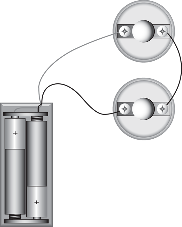
Whenever you have circuits that consist of more than one component, those components must be linked together. The two ways to connect components in a circuit are in series and in parallel. Figure 1-11 illustrates how you might use series and parallel circuits to connect two lamps in a single circuit.

FIGURE 1-11: Lamps connected in series and in parallel.
In a series connection, components are connected end to end, so that current flows first through one, then through the other. As you can see in the first circuit in Figure 1-11, the current goes through one lamp and then the other. The lamps are strung together end to end.
One drawback of series connections is that if one component fails in a way that results in an open circuit, the entire circuit is broken and none of the components will work. For example, if either one of the lamps in the series circuit in Figure 1-11 burns out, neither lamp will work. That’s because current must flow through both lamps for the circuit to be complete.
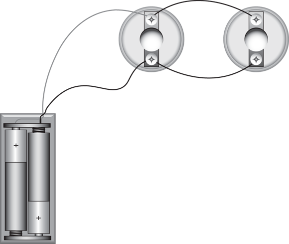
In the parallel connection shown in Figure 1-12, each lamp has its own direct connection to the battery. This arrangement avoids the if-one-fails-they-all-fail nature of series connections. In a parallel connection, the components do not depend on each other for their connection to the battery. Thus, if one lamp burns out, the other will continue to burn.

FIGURE 1-12: Lamps connected in series.
An interesting thing happens with voltage when components are connected in series: The voltages present at each component are divided up. For example, in a circuit with a 3 V battery and two identical lamps connected in series, each lamp will see only one and a half volts. If you connected three identical lamps in series, each lamp would see only one volt.
You can measure the voltage seen by any component in a circuit by setting your multimeter to an appropriate voltage range and then touching the leads to both sides of the component. The voltage you measure there is called the component’s voltage drop.
Building a Series Lamp Circuit
In Project 3, you build a circuit that connects two lamps in series, a simple circuit. Then, you use your multimeter to measure the voltages at various points in the circuit. The completed project is shown in Figure 1-12.
Project 3: A Series Lamp Circuit
In this project, you connect two lamps in a series circuit. The lamps are powered by a pair of AA batteries. To build this project, you need a small Phillips-head screwdriver, wire cutters, wire strippers, and a multimeter.

Parts
- Two AA batteries
- One battery holder (RadioShack 2700408)
- Two lamp holders (RadioShack 2720357)
- Two 2.33 V flashlight lamps (RadioShack 27201175)
- One 6-inch 22-gauge stranded wire
Steps
- Strip
 inch of insulation from each end of the wire.
 - Attach the red lead from the battery holder to one of the terminals on one of the lamp holders.
- Attach the black lead to one of the terminals on the other lamp holder.
- Use the 6-inch wire to connect the unused terminal of the first lamp holder to the unused terminal of the second lamp holder.
-
Insert the batteries into the holder.
Both lamps light.
Notice that the lamps are dim. That’s because in a series circuit made with two identical lamps, each of the two lamps sees only half the total voltage. -
Remove one of the lamps from its holder.
The other lamp goes out. This is because in a series circuit, a failure in any one component breaks the circuit so none of the other components will work.
- Replace the lamp you removed in Step 6.
- Set your multimeter to a DC voltage range that can read at least 3 volts.
-
Touch the leads to the two terminals on the first lamp holder.
The multimeter should read approximately 1.5 V. (If you’re using an analog meter and the needle moves backward, just reverse the leads.)
-
Touch the leads to the two terminals on the other lamp holder.
Again, the multimeter should read approximately 1.5 V.
-
Touch the red lead of the meter to the terminal that the red lead from the battery is connected to, and touch the black meter lead to the terminal that the black battery lead is connected to.
This measures the voltage across both lamps combined. The meter will indicate 3 V.
Building a Parallel Lamp Circuit
In Project 4, you build a circuit that connects two lamps in parallel and you use your multimeter measure voltages within various points in the circuit. The completed project is shown in Figure 1-13.

FIGURE 1-13: Lamps connected in parallel.
Project 4: A Parallel Lamp Circuit
In this project, you connect two lamps in a series circuit. The lamps are powered by a pair of AA batteries. To build this project, you need a small Phillips-head screwdriver, wire cutters, wire strippers, and a multimeter.

Parts
- Two AA batteries
- 1 battery holder (RadioShack 2700408)
- Two lamp holders (RadioShack 2720357)
- Two 2.33 V flashlight lamps (RadioShack 2721175)
- Two 6-inch 22-gauge stranded wires
Steps
- Strip
 inch of insulation from each end of the wires.
 - Attach the red lead from the battery holder to one of the terminals on the first lamp holder.
- Attach the black lead to the other terminals on the first lamp holder.
-
Use the two wires to connect each of the terminals on the first lamp holder to the terminals on the second lamp holder.
This wiring connects the two lamp holders in parallel.
-
Insert the batteries.
The lamps light, brighter than when you connected them in series in Project 3. Because the lamps are connected in parallel, removing one of the lamps does not break the circuit to the other lamp.
-
Remove one of the lamps.
Notice that the other lamp remains lit.
- Replace the lamp you removed in Step 6.
- Set your multimeter to a DC voltage range that can read at least 3 volts.
-
Touch the leads of your multimeter to the two terminals on the first lamp holder.
Make sure you touch the red meter lead to the terminal that the red battery lead is connected to and the black meter lead to the terminal that the black battery lead is attached to.
Note that the voltage reads a full 3 V.
-
Touch the meter leads to the terminals on the second lamp stand.
Note that the voltage again reads 3 V. When components are connected in parallel, the voltage is not divided among them. Instead, each component sees the same voltage. That’s why the lamps light at full intensity in the parallel circuit.
Using Switches in Series and Parallel
Just as lamps can be connected in series or parallel, switches can also be connected in series or parallel. For example, Figure 1-14 shows two circuits that each use a pair of SPST switches to turn a lamp on or off. In the first circuit, the switches are wired in series. In the second, the switches are wired in parallel.

FIGURE 1-14: Schematic diagrams for series and parallel switch circuits.
The interesting thing to note about wiring switches in series is that both switches must be closed in order to complete the circuit. A great example of switches wired in series is in the typical nuclear-war movie, where two people must flip a switch in order to launch the missiles. Switches wired in series means that Denzel Washington and Gene Hackman must both agree to launch the missiles.
When switches are wired in parallel, closing either switch will complete the circuit. Thus, parallel switches are often used when you want the convenience of controlling a circuit from two different locations. If the nuclear missile switches were wired in parallel, either Denzel Washington or Gene Hackman could fire the missiles.
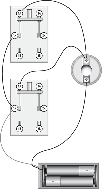
Building a Series Switch Circuit
Project 5 presents a simple project that uses two switches to open or close a circuit that lights a lamp. The switches are wired in series, so both switches must be closed to light the lamp. Figure 1-15 shows the completed project.
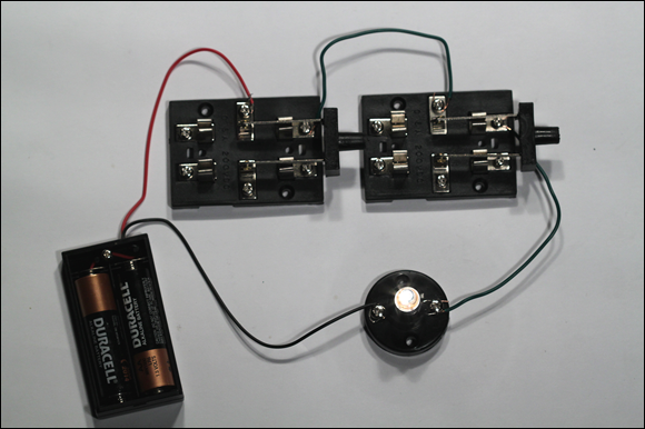
FIGURE 1-15: The assembled series switch circuit.
Project 5: A Series Switch Circuit
In this project, you build a simple circuit that uses two knife switches to control a single lamp. To complete this project, you need a small Phillips-head screwdriver, wire cutters, and wire strippers.

Parts
- Two AA batteries
- One battery holder (RadioShack 2700408)
- One lamp holder (RadioShack 2720357)
- One 2.33 V flashlight lamp (RadioShack 2721175)
- Two DPDT knife switches (RadioShack 2751537)
- Two 6-inch 22-gauge stranded wires
Steps
- Strip
 inch of insulation from each end of the wires.
 -
Open both switches.
Move the handles to the upright position so the contacts are not connected.
- Attach the red lead from the battery holder to terminal 1X of one of the switches.
- Attach the black lead to one of the terminals on the lamp holder.
- Connect one of the 6-inch wires from terminal 1A of the first switch to terminal 1X of the second switch.
- Connect the other 6-inch wire from terminal 1A of the second switch to on the unused terminal of the lamp holder.
- Insert the batteries into the holder.
-
Close the first switch.
Notice the lamp does not light.
-
Close the second switch.
The lamp lights. With two switches in series, both switches must be closed for the circuit to be complete.
Building a Parallel Switch Circuit
In Project 6, you build a simple circuit that uses two switches wired in parallel to control a lamp. Because the switches are wired in parallel, the lamp will light if either of the switches is closed. Figure 1-16 shows the completed project.
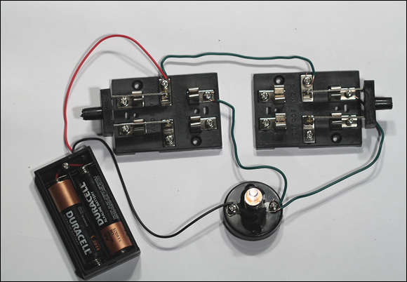
FIGURE 1-16: The assembled parallel switch circuit.
Project 6: A Parallel Switch Circuit
This project is a circuit that uses two switches wired in parallel to control a lamp. To complete this project, you need a small Phillips-head screwdriver, wire cutters, and wire strippers.

Parts
- Two AA batteries
- One battery holder (RadioShack 2700408)
- One lamp holder (RadioShack 2720357)
- One 2.33 V flashlight lamp (RadioShack 2721175)
- Two DPDT knife switches (RadioShack 2751537)
- Three 6-inch 22-gauge stranded wires
Steps
- Strip
 inch of insulation from each end of the wires.
 -
Open both switches.
Move the handles to the upright position so the contacts are not connected.
- Attach the red lead from the battery holder to terminal 1X of the first switch.
- Attach the black lead to the first terminal on the lamp holder.
-
Use the first 6-inch wire to connect terminal 1X of the first switch to terminal 1X of the second switch.
Be sure to leave the red battery wire in place at terminal 1X on the first switch. Terminal 1X on the first switch should have two wires: the red battery terminal and the wire going to terminal 1X of the second switch.
- Use the second 6-inch wire to connect terminal 1A of the first switch to the second terminal of the lamp holder.
-
Use the third 6-inch wire to connect terminal 1A of the second switch to the second terminal of the lamp holder.
In other words, the unused terminal of the lamp holder should be connected to terminal 1A on both knife switches.
- Insert the batteries.
-
Close one of the switches.
The lamp lights.
-
Open the switch you closed in Step 9 and then close the other switch.
Again, the lamp lights. When switches are connected in parallel, current flows through the circuit when either of the switches is closed.
-
Close both switches.
The lamp remains lit because current continues to flow when both switches are closed.
-
Open both switches.
The lamp goes out. With switches wired in parallel, at least one of the switches must be closed in order for current to flow.
Switching between Two Lamps
In Project 7, you build a simple circuit that uses a single pole, double throw (SPDT) to switch a circuit between one of two lamps. In other words, one of two lamps will light depending on the position of the switch. This type of switching is a common requirement in electronic circuits. Figure 1-17 shows the completed circuit.
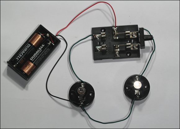
FIGURE 1-17: The switch controls two lamps.
Project 7: Controlling Two Lamps with One Switch
In this project, you build a circuit that uses a single switch to control two lamps. When the switch is in the first position, the first lamp lights and the second lamp is dark. When the switch is in the second position, the second lamp lights and the first lamp is dark. You need a small Phillips-head screwdriver, wire cutters, and wire strippers to build this project.


Parts
- Two AA batteries
- One battery holder (RadioShack 2700408)
- Two lamp holders (RadioShack 2720357)
- Two 2.33 V flashlight lamps (RadioShack 2721175)
- One DPDT knife switch (RadioShack 2751537)
- Three 6-inch 22-gauge stranded wires
Steps
- Strip
 inch of insulation from each end of the wires.
 -
Open the switch.
Lift the handle into the upright position so the contacts are not connected.
- Attach the red lead from the battery holder to terminal 1X of the switch.
- Attach the black lead to one of the terminals on the first lamp holder.
- Connect one of the 6-inch wires from terminal 1A of the switch to one terminal of the second lamp holder.
- Connect another 6-inch wire from terminal 1B of the switch to the unused terminal of the first lamp holder.
- Use the third 6-inch wire to connect the unused terminal of the second lamp holder to the terminal of the first lamp holder that the black battery lead is connected to.
- Insert the lamps into the lamp holders.
- Insert the batteries into the holder.
-
Flip the switch to the A position.
The second lamp lights.
-
Change the switch to the B position.
The first lamp lights.
An interesting variant of the circuit in Project 7 uses both poles of the DPDT knife switch to switch the circuit on both the negative and positive sides of the lamp. For this circuit, you need four 6-inch wires. Connect the six terminals of the DPDT switch as follows:
|
Terminal |
Connect To |
|
1X |
Red battery lead |
|
1A |
Terminal 1 of second lamp |
|
1B |
Terminal 1 of first lamp |
|
2X |
Black battery lead |
|
2A |
Terminal 2 of second lamp |
|
2B |
Terminal 2 of first lamp |
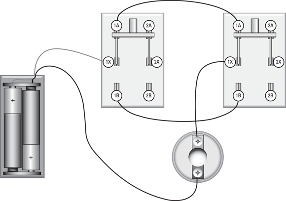
Figure 1-18 shows this circuit assembled.
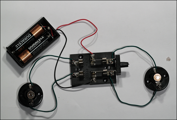
FIGURE 1-18: Another way to control two lamps.
Building a Three-Way Lamp Switch
Many homes and offices have hallways that have a light switch on both ends. You can turn the light on or off by flipping either switch. This kind of switching arrangement is called a three-way switch.
Have you ever wondered how these three-way switches work? If you think about it, the switches are puzzling. If the light is on, flipping either switch will turn it off. If the light is off, flipping either switch will turn it on. Say you flip one switch to its On position and the light goes on. Now go to the other switch, flip it to turn the light off, and come back to the first switch. It is still in its On position, but the light is off. To turn the light back on, you can flip the first switch again.
In other words, sometimes the light is on when the switch is up, sometimes it is on when the switch is down. How can this be?
The answer is that both switches are single pole, double throw switches, and they are wired in series such that either both switches must be up or both must be down to complete the circuit. If one switch is up and the other is down, the circuit is open.
Sometimes electricians install one of the switches upside down or wire the three-way switch backwards just to confuse you. Then, the switches work backwards: If both switches are up or if both switches are down, the circuit is open and the lamp lights only when one switch is up and the other is down. But that’s not the normal way to wire a three-way switch.
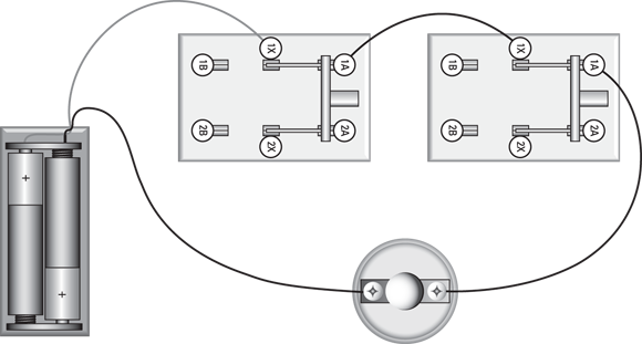
In Project 8, you build a simple circuit that uses two single pole, double throw switches to show how a three-way light switch works. Figure 1-19 shows the completed project.
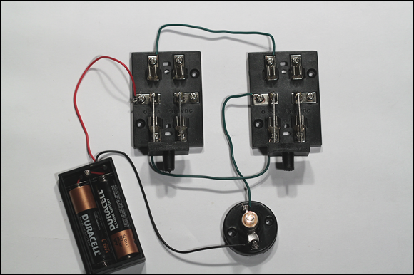
FIGURE 1-19: The completed three-way light switch circuit.
Project 8: A Three-Way Light Switch
In this project, you create a three-way switch circuit in which a single lamp is controlled by either of two switches. You need a small Phillips-head screwdriver, wire cutters, and wire strippers to complete this project.

Parts
- Two AA batteries
- One battery holder (RadioShack 2700408)
- One lamp holder (RadioShack 2720357)
- One 2.33 V flashlight lamp (RadioShack 2721175)
- Two DPDT knife switches (RadioShack 2751537)
- Three 6-inch 22-gauge stranded wires
Steps
- Strip
 inch of insulation from each end of the wires.
 -
Open both switches.
Move the handles to their upright positions so the contacts are not connected.
- Attach the red lead from the battery holder to terminal 1X of the first switch.
- Attach the black lead to one of the terminals on the lamp holder.
- Connect one of the 6-inch wires from terminal 1A of the first switch to terminal 1A of the second switch.
- Connect another 6-inch wire from terminal 1B of the first switch to terminal 1B of the second switch.
- Connect the last 6-inch wire from terminal 1X of the second switch to the unused terminal of the lamp socket.
- Insert the lamps into the lamp holder.
- Insert the batteries into the holder.
-
Flip the switches to see the operation of the three-way switch.
The lamp lights only when both switches are in the A position or when both switches are in the B position.
Reversing Polarity
The final project in this chapter — Project 9 — shows you a common trick: using a DPDT switch to reverse the polarity of a circuit. One common use for this trick is powering a DC motor with the circuit. When you reverse the polarity of a DC motor, the motor spins in the opposite direction. Thus, you can use a DPDT switch to control the direction in which a DC motor turns. Figure 1-20 shows the assembled project.
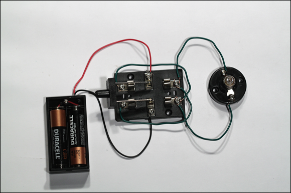
FIGURE 1-20: The assembled polarity-reversing circuit.
Project 9: A Polarity-Reversing Circuit
In this project, you build a circuit that uses a DPDT switch to reverse a circuit’s polarity. In other words, flipping the switch from one position to the other reverses the direction in which current flows through the circuit. To build this circuit, you need a small Phillips-head screwdriver, wire cutters, and wire strippers.


Parts
- Two AA batteries
- One battery holder (RadioShack 2700408)
- One lamp holder (RadioShack 2720357)
- One 2.33 V flashlight lamp (RadioShack 2721175)
- One DPDT knife switch (RadioShack 2751537)
- Four 6-inch 22-gauge stranded wires
Steps
- Strip
 inch of insulation from each end of the wires.
 -
Open the switch.
Move the handles to their upright positions so the contacts are not connected.
- Attach the red lead from the battery holder to terminal 1X of the switch.
- Attach the black lead from the battery to terminal 2X of the switch.
- Connect the first 6-inch wire from terminal 1B of the switch to terminal 2A of the switch.
- Connect the second 6-inch wire from terminal 2B of the switch to terminal 1A of the switch.
- Connect the third 6-inch wire from terminal 1A of the switch to one terminal of the lamp socket.
- Connect the fourth 6-inch wire from terminal 2A of the switch to the other terminal of lamp socket.
- Insert the lamps into the lamp holder.
- Insert the batteries into the battery holder.
-
Flip the switch to the A position and measure the voltage at the lamp.
Touch the red meter probe to the lamp terminal that’s connected to switch terminal 1A, and touch the black meter probe to the other lamp terminal. You should read approximately
 .
. -
Flip the switch to the B position and measure the voltage again.
You should read approximately
 . (If you’re using an analog meter, you have to reverse the probes to read the negative voltage.)