
Chapter 4
Adding Sound and Motion to Your BASIC Stamp Projects
IN THIS CHAPTER
![]() Making sound with a piezo speaker
Making sound with a piezo speaker
![]() Using the FREQOUT command to create frequencies
Using the FREQOUT command to create frequencies
![]() Making music
Making music
![]() Creating motion with a servo
Creating motion with a servo
![]() Using the PULSOUT command to generate servo pulses
Using the PULSOUT command to generate servo pulses
In this chapter, you learn how to work with devices that add sound and motion to your BASIC Stamp projects. To create sound, you can add a piezo speaker to create audible output tones. This is useful in situations where your BASIC Stamp program might need to get someone’s attention or when you want to create a sound effect. To create motion, you can add a very useful device called a servo, which lets you control mechanical motion with a BASIC Stamp program.
Using a Piezo Speaker with a BASIC Stamp
The BASIC Stamp Activity Kit comes with a small piezoelectric speaker, which you can connect directly to an I/O pin to create beautiful music. Well, the music probably won’t be so beautiful, but you can coax the BASIC Stamp into emitting a variety of squeaks, burps, and squelches that resemble musical notes. And you can create interesting sound effects like police sirens or chirping crickets. Figure 4-1 shows this handy little speaker.
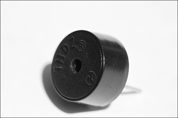
FIGURE 4-1: The piezoelectric speaker that comes with the BASIC Stamp Activity Kit.
If you didn’t purchase the BASIC Stamp Activity Kit, you can order the piezo speaker directly from the Parallax website (www.parallax.com) for $1.95.
Note that the piezo speaker is polarized, so when you connect it to an I/O pin, be sure to connect the + terminal to the I/O pin and the other terminal to Vss (ground), as shown in the schematic in Figure 4-2.

FIGURE 4-2: Connecting a piezo speaker to a BASIC Stamp I/O pin.
Using the FREQOUT command
Programming a piezo speaker is remarkably simple. PBASIC includes a command called FREQOUT that sends a frequency of your choice to an output pin. Thus, you can create an audible tone on a piezo speaker by using the FREQOUT command, using the following syntax:
FREQOUT pin, duration, frequency
Here’s how that syntax works:
- pin is simply the pin number that you want to send the frequency to.
- duration is simply the length of time in milliseconds you want the frequency to play. And
- frequency is the frequency in hertz that you want to generate.
For example, the following command generates a 2,000 Hz frequency for five seconds on pin 8:
FREQOUT 8, 5000, 2000
You can easily create a beeping sound by alternately sending short bursts of a frequency to the speaker followed by a brief pause. For example:
DO
FREQOUT 8,250, 1500
PAUSE 250
LOOP
This code repeatedly sends a 1,500 Hz signal for a quarter of a second, and then pauses for a quarter of a second. The result is a beep-beep-beep sound.
Testing the piezo speaker
Project 53 shows how to build a simple circuit that connects a piezo speaker to a BASIC Stamp so you can create audible output; two push buttons vary the sound output. Figure 4-3 shows the circuit.
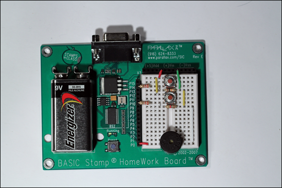
FIGURE 4-3: A piezo speaker connected to a BASIC Stamp (Project 53).
The piezo speaker here is actually very quiet. This is normal; the piezo speaker draws just 1 mA, and so can’t make a lot of noise. The speaker is loudest with frequencies between 4,500 and 5,500 Hz.
Project 53: Creating Sound with a Piezo Speaker
In this project, you connect a piezo speaker a BASIC Stamp HomeWork board or Board of Education to run programs that generate sound. The circuit also includes two push buttons (on pins 10 and 14) that you can use to vary the sound produced by the Stamp program.


Parts
- One computer with BASIC Stamp Editor software installed
- One BASIC Stamp HomeWork board or Board of Education
- One 9 V battery
- One USB cable
- One USB-to-serial adapter
- One Piezo speaker
- Two normally open push buttons
- Two
 resistors
 - Two
 resistors
 - Six jumper wires
Steps
-
Insert the piezo speaker.
The positive lead goes in E17, the negative lead in F17.
-
Insert the two push buttons.
SW1 goes in E1, F1, E3, and F3.
SW2 goes in E5, F5, E7, and F7.
-
Insert the resistors.
R1 (
 ): Pin 14 to B3
R2 (
 ): E4 to F4
R3 (
 ): Pin 10 to B7
R4 (
 ): E8 to F8
 -
Insert the jumper wires.
Vdd to D1
Vss to G4
C1 to C5
D3 to D4
H4 to H8
D7 to D8
J8 to J17
Pin 0 to A17
- Open the BASIC Stamp Editor.
-
Connect your BASIC Stamp to the computer and identify it in the Stamp Editor.
For more information about how to do this, refer to Chapter 1 of this minibook.
-
Type the Beeper program into the Editor program window, and then save the file.
The Beeper program is shown here:
' {$STAMP BS2}
' {$PBASIC 2.5}
DO
FREQOUT 0, 250, 1500
PAUSE 250
LOOP -
Choose Run⇒ Run.
If you prefer, you can click the Run button in the toolbar or press F9.
When you choose the Run command, the program is downloaded to the BASIC Stamp. When the program is downloaded, it automatically starts to run on the Stamp.
-
Now try the programs in Listings 4-1 and 4-2.
These programs vary the tone in different ways to demonstrate the versatility of the FREQOUT command.
Playing with sound effects
With creative use of the FREQOUT command, PAUSE commands, and FOR-NEXT loops, you can create some interesting and at times annoying sound effects. The idea is to use short durations in the FREQUOUT command and use FOR-NEXT loops or some other means to vary the frequency. You can also use PAUSE commands between tones to create beeping or clicking effects.
The best way to learn what kinds of sound effects are possible with the FREQOUT command is to experiment. Listings 4-1, 4-2, and 4-3 give three sample programs you can run using the circuit you created in Project 53. Use these programs as starting points for your own experiments.
The program in Listing 4-1 plays two different beeping sounds when you press one of the push buttons. If you press Switch1 (on pin 14), a 5,000 Hz tone beeps twice per second. If you press Switch2 (on pin 10), a 5,000 Hz tone beeps five times per second.
LISTING 4-1 Generating Two Different Types of Beeping Sounds
' Sound Program
' Doug Lowe
' July 15, 2011
'
' This program creates fast and slow beeping sounds.
' A piezo speaker must be connected to pin 0.
' The normally open push-button switches must be connected
' to pins 10 and 14.
' {$STAMP BS2}
' {$PBASIC 2.5}
Speaker PIN 0
Switch1 PIN 10
Switch2 PIN 14
DO
IF Switch1 = 1 THEN
FREQOUT Speaker,250, 5000
PAUSE 250
ELSEIF Switch2 = 1 THEN
FREQOUT Speaker,100, 5000
PAUSE 100
ENDIF
LOOP
Listing 4-2 shows how you can use FREQOUT within a FOR-NEXT loop to create a continuously rising or falling tone, much like a police siren. The program varies the frequency from 3,000 to 5,000 Hz. When you press either of the push buttons, the rate at which the pitch rises and falls changes.
The rate at which the pitch rises or falls is governed by a variable named Time. Each time through the FOR-NEXT loop, the program calls a subroutine named SetTime, which checks the status of the push-button switches and changes the Time variable if either of the switches is down. That’s how the program changes the rate of the pitch change when the buttons are pressed.
LISTING 4-2 Generating a Siren Effect
' Siren Effect Program
' Doug Lowe
' July 15, 2011
'
' This program generates a rising and falling pitch
' similar to a police siren. The rate at which the pitch
' rises and falls changes if you press either of the two
' push buttons.
' {$STAMP BS2}
' {$PBASIC 2.5}
Speaker PIN 0
Switch1 PIN 10
Switch2 PIN 14
Frequency VAR Word
Time VAR Word
DO
FOR Frequency = 3000 TO 5000 STEP 15
GOSUB SetTime
FREQOUT 0, Time, Frequency
NEXT
FOR Frequency = 5000 TO 3000 STEP 15
GOSUB SetTime
FREQOUT 0, Time, Frequency
NEXT
LOOP
SetTime:
Time = 15
IF Switch1 = 1 THEN
Time = 5
ENDIF
IF Switch2 = 1 THEN
Time = 2
ENDIF
RETURN
Listing 4-3 shows a program that plays two songs on the piezo speaker: “Mary Had a Little Lamb” and “Good Morning to All.” The former is played when you press SW1; the latter is played when you press SW2.
To simplify the code that generates the musical notes, the program defines several constants that represent the frequency for each of the notes required by the songs. For example, the constant NoteC6 is 1046, the frequency in Hz of C in the sixth octave of a piano keyboard. The constants span two full octaves, which is plenty of range for the songs to be played. Both songs are played in the key of C, so no flats or sharps are required. (If this musical stuff makes no sense to you, don’t worry about it — this is an electronics book, not a music book.)
The program also sets up constants for the duration of a quarter note, half note, and whole note. The constants make it easy to specify a particular pitch for a particular duration in a FREQOUT command. Thus, playing a melody is simply a matter of writing a sequence of FREQOUT commands to play the correct notes for the correct durations in the correct order. That’s precisely what the subroutines labeled Mary and Morning do.
LISTING 4-3 Making Music with a BASIC Stamp
' Song Program
' Doug Lowe
' July 15, 2011
'
' This program plays one of two songs on the piezo
' speaker on pin 0. If SW1 on pin 14 is pressed, the
' program plays "Mary Had a Little Lamb." If SW2 on pin
' 10 is pressed, the program plays "Good Morning to
' All."
' {$STAMP BS2}
' {$PBASIC 2.5}
SW1 PIN 14
SW2 PIN 10
Speaker PIN 0
NoteC6 CON 1046
NoteD6 CON 1175
NoteE6 CON 1318
NoteF6 CON 1397
NoteG6 CON 1568
NoteA6 CON 1760
NoteB6 CON 1975
NoteC7 CON 2093
NoteD7 CON 2349
NoteE7 CON 2637
NoteF7 CON 2794
NoteG7 CON 3136
NoteA7 CON 3520
NoteB7 CON 3951
NoteC8 CON 4186
Whole CON 1000
Half CON 500
Quarter CON 250
DO
IF SW1 = 1 THEN
GOSUB Mary
ENDIF
IF SW2 = 1 THEN
GOSUB Morning
ENDIF
LOOP
Mary:
FREQOUT Speaker, Quarter, NoteE7 ' Mar-
FREQOUT Speaker, Quarter, NoteD7 ' y
FREQOUT Speaker, Quarter, NoteC7 ' Had
FREQOUT Speaker, Quarter, NoteD7 ' a
FREQOUT Speaker, Quarter, NoteE7 ' Lit-
FREQOUT Speaker, Quarter, NoteE7 ' tle
FREQOUT Speaker, Quarter, NoteE7 ' Lamb
PAUSE Quarter
FREQOUT Speaker, Quarter, NoteD7 ' Lit-
FREQOUT Speaker, Quarter, NoteD7 ' tle
FREQOUT Speaker, Quarter, NoteD7 ' Lamb
PAUSE Quarter
FREQOUT Speaker, Quarter, NoteE7 ' Lit-
FREQOUT Speaker, Quarter, NoteG7 ' tle
FREQOUT Speaker, Quarter, NoteG7 ' Lamb
PAUSE Quarter
FREQOUT Speaker, Quarter, NoteE7 ' Mar-
FREQOUT Speaker, Quarter, NoteD7 ' y
FREQOUT Speaker, Quarter, NoteC7 ' Had
FREQOUT Speaker, Quarter, NoteD7 ' a
FREQOUT Speaker, Quarter, NoteE7 ' Lit-
FREQOUT Speaker, Quarter, NoteE7 ' tle
FREQOUT Speaker, Quarter, NoteE7 ' Lamb
FREQOUT Speaker, Quarter, NoteE7 ' Its
FREQOUT Speaker, Quarter, NoteD7 ' Fleece
FREQOUT Speaker, Quarter, NoteD7 ' Was
FREQOUT Speaker, Quarter, NoteE7 ' White
FREQOUT Speaker, Quarter, NoteD7 ' As
FREQOUT Speaker, Quarter, NoteC7 ' Snow
PAUSE Half
RETURN
Morning:
FREQOUT Speaker, Half, NoteC7 ' Good
FREQOUT Speaker, Half, NoteD7 ' Morn-
FREQOUT Speaker, Half, NoteC7 ' ing
FREQOUT Speaker, Half, NoteF7 ' To
FREQOUT Speaker, Whole, NoteE7 ' You
FREQOUT Speaker, Half, NoteC7 ' Good
FREQOUT Speaker, Half, NoteD7 ' Morn-
FREQOUT Speaker, Half, NoteC7 ' ing
FREQOUT Speaker, Half, NoteG7 ' To
FREQOUT Speaker, Whole, NoteF7 ' You
FREQOUT Speaker, Half, NoteC7 ' Good
FREQOUT Speaker, Half, NoteC8 ' Morn-
FREQOUT Speaker, Half, NoteA7 ' ing
FREQOUT Speaker, Half, NoteF7 ' Dear
FREQOUT Speaker, Half, NoteE7 ' Child-
FREQOUT Speaker, Whole, NoteD7 ' ren
FREQOUT Speaker, Half, NoteB7 ' Good
FREQOUT Speaker, Half, NoteA7 ' Morn-
FREQOUT Speaker, Half, NoteF7 ' ing
FREQOUT Speaker, Half, NoteG7 ' To
FREQOUT Speaker, Whole, NoteF7 ' All
RETURN
Using a Servo with a BASIC Stamp
A servo is a special type of motor that is designed to rotate to a particular position and hold that position until told to rotate to a different position. Hobby servos are frequently used in radio-controlled vehicles such as airplanes, boats, and cars, but there are many other uses for servos. For example, I often use them in Halloween props to add movement such as eyes or a mouth.
The BASIC Stamp Activity Kit comes with a servo that you can use to learn how to write programs that control servos. You can also purchase servos directly from Parallax (www.parallax.com) or from most hobby stores. Figure 4-4 shows a typical hobby servo.
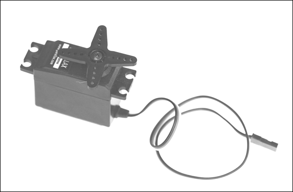
FIGURE 4-4: A typical hobby servo.
Connecting a servo to a BASIC Stamp
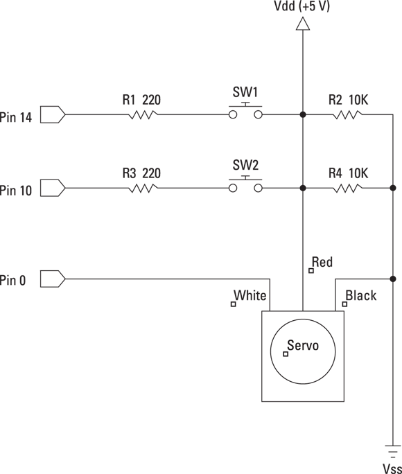
Servos use a special three-conductor cable to provide power and a control signal that tells the servo what position it should move to and hold. The cable’s three wires are colored red, black, and white and have the following functions:
- Red: Supplies the voltage required to operate the servo. For more servos, this voltage can be anywhere between
 and
and  . On a BASIC Stamp HomeWork board, you should connect this to one of the Vdd pins.
 - Black: The ground connection. On the BASIC Stamp HomeWork board, you should connect it to a Vss pin.
- White: The control wire; it connects to one of the BASIC Stamp’s I/O pins.
Figure 4-5 shows how these wires should be connected in a BASIC Stamp circuit.

FIGURE 4-5: Connecting a servo to a BASIC Stamp.
The control wire controls the position of the servo by sending the servo a series of pulses approximately 20 ms apart. The length of each one of these pulses determines the position that the servo rotates to and holds.
Most hobby servos have a range of motion of 180 degrees — that is, one-half of a complete revolution. The complete range of pulse durations is 0.5 ms to 2.5 ms, where 0.5 ms pulses move the servo to its minimum position (0 degrees), and 2.5 ms pulses move the servo to its maximum position (180 degrees). To hold the servo at the center point of this range (90 degrees), the pulses should be 1.5 ms in duration.
To connect a servo to a BASIC Stamp HomeWork Board, you must use a 3-pin header, which comes with the BASIC Stamp Activity Kit and is pictured in Figure 4-6. This header consists of three pins that you can plug in to the solderless breadboard. Then, you can plug the servo cable into the adapter.
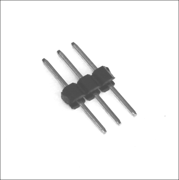
FIGURE 4-6: 3-pin header for connecting the servo to a BASIC Stamp HomeWork Board.
Programming a servo in PBASIC
The easiest way to control a servo from a BASIC Stamp microcontroller is to use the PULSOUT command. This command sends a pulse of any duration you specify to an I/O pin of your choosing. The syntax of this command is as follows:
PULSOUT pin, duration
You specify the duration in units of two microseconds. A microsecond is one-millionth of a second. There are one thousand microseconds in a millisecond. Thus, to send a 1.5 ms pulse with the PULSOUT command, you must specify 750 as the duration, like this:
PULSOUT 0,750
Here, a 1.5 ms pulse is sent to pin 0.
To make your servo-programming life easier, Table 4-1 lists the duration values you should use for a typical hobby servo for various angles.
TABLE 4-1 PULSOUT Duration Values for Servo Control
|
Angle |
Duration |
Angle |
Duration |
|
0 |
250 |
95 |
778 |
|
5 |
278 |
100 |
806 |
|
10 |
306 |
105 |
833 |
|
15 |
333 |
110 |
861 |
|
20 |
361 |
115 |
889 |
|
25 |
389 |
120 |
917 |
|
30 |
417 |
125 |
944 |
|
35 |
444 |
130 |
972 |
|
40 |
472 |
135 |
1000 |
|
45 |
500 |
140 |
1028 |
|
50 |
528 |
145 |
1056 |
|
55 |
556 |
150 |
1083 |
|
60 |
583 |
155 |
1111 |
|
65 |
611 |
160 |
1139 |
|
70 |
639 |
165 |
1167 |
|
75 |
667 |
170 |
1194 |
|
80 |
694 |
175 |
1222 |
|
85 |
722 |
180 |
1250 |
|
90 |
750 |
For example, to move the servo on pin 0 to 75 degrees, use this command:
PULSOUT 0,667
Remember that to hold its position, a servo needs a constant stream of pulses approximately 20 ms apart. Thus, PULSOUT commands are usually contained in either DO loops or FOR-NEXT loops. For example, here’s a bit of code that keeps the servo on pin 0 at 45 degrees indefinitely:
DO
PULSOUT 0,500
PAUSE 20
LOOP
Listing 4-4 shows a complete program that moves the servo to 45 degrees when SW1 (a push button on pin 14) is pressed and 135 degrees when SW2 (a push button on pin 10) is pressed.
LISTING 4-4 A Servo Control Program
' Servo Control Program
' Doug Lowe
' July 15, 2011
'
' This program moves a servo to one of two when SW1 is
' pressed and returns the servo to center position when
' SW2 is pressed.
' {$STAMP BS2}
' {$PBASIC 2.5}
Servo PIN 0
SW1 PIN 14
SW2 PIN 10
Position VAR Word
Position = 500
DO
IF SW1 = 1 THEN
Position = 500
ENDIF
IF SW2 = 1 THEN
Position = 750
ENDIF
PULSOUT Servo, Position
PAUSE 20
LOOP
Building a servo project
Project 54 shows you how to build a complete circuit that uses a servo as well as two push buttons. This circuit is capable of running the program that was shown in Listing 4-4. Figure 4-7 shows the assembled project.
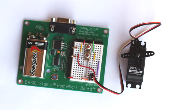
FIGURE 4-7: A BASIC Stamp project that controls a servo (Project 54).
 For projects that require multiple servos or a lot of other work besides managing the servo, you should consider using Parallax’s Propeller chip instead of a BASIC Stamp. The Propeller processor is designed for programs that have to do several things at once, such as managing servos. The propeller costs a little more than a BASIC Stamp and its programming language is a little more complicated, but in the end, controlling multiple servos is much easier with a Propeller than with a BASIC Stamp.
Project 54: Using a Servo with a BASIC Stamp
In this project, you connect a servo to a BASIC Stamp HomeWork Board. The circuit also includes two push buttons (on pins 10 and 14) that you can use to control the action of the servo.
Parts
- One computer with BASIC Stamp Editor software installed
- One BASIC Stamp HomeWork board or Board of Education
- One 9 V battery
- One USB cable
- One USB-to-serial adapter
- One hobby servo
- One 3-pin male-to-male header
- Two normally open push buttons
- Two
 resistors
 - Two
 resistors
 - Eight jumper wires
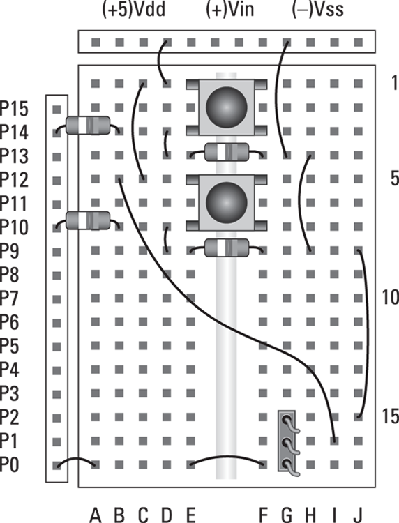
Steps
-
Insert the 3-pin header.
The three pins go in G15, G16, and G17.
-
Insert the two push buttons.
SW1 goes in E1, F1, E3, and F3.
SW2 goes in E5, F5, E7, and F7.
-
Insert the resistors.
R1 (
 ): Pin 14 to B3
R2 (
 ): E4 to F4
R3 (
 ): Pin 10 to B7
R4 (
 ): E8 to F8
 -
Insert the jumper wires.
Vdd to D1
Vss to G4
B5 to I16
C1 to C5
D3 to D4
H4 to H8
D7 to D8
J8 to J15
Pin 0 to A17
E17 to F17
-
Connect the servo.
Plug the 3-pin servo connector into the 3-pin male-to-male header. Connect the white wire to G17.
- Open the BASIC Stamp Editor.
-
Connect your BASIC Stamp to the computer and identify it in the Stamp Editor.
For more information about how to do this, refer to Chapter 1 of this minibook.
-
Type the Servo program into the Editor program window, and then save the file.
The Servo program is shown here:
' {$STAMP BS2}
' {$PBASIC 2.5}
X VAR Byte
DO
FOR X = 1 TO 200
PULSOUT 0, 350
PAUSE 10
NEXT
FOR X = 1 TO 200
PULSOUT 0, 1150
PAUSE 10
NEXT
LOOP -
Choose Run⇒ Run.
If you prefer, you can click the Run button in the toolbar or press F9.
When you choose the Run command, the program is downloaded to the BASIC Stamp. After the program is downloaded, it automatically starts to run on the Stamp. The servo should alternate from about 20 degrees to about 165 degrees once per second.
-
Now try the program in Listing 4-4.
This program uses the switches to control the servo’s action.