Chapter 5
Networking Devices
In this chapter, I'll tell you all about the networking devices I've introduced so far. I'll go into much greater detail about each device, and yes—I'm going to present even more of them to you! Because all the components that you'll learn about shortly are typically found in today's networks and internetworks, it's very important that you be familiar with them.
We'll start by covering the more common network devices that you would be most likely to come across and then move on to discuss some of the more specialized devices that you may or may not always find running in a network.
I'll finish the chapter by using examples to discuss how routers, hubs, and switches work within internetworks today.
Common Network Connectivity Devices
By now, you should be fairly savvy regarding the various types of network media and connections, so it's time to learn about some of the devices they hook up to that are commonly found on today's networks.
First, I'll define the basic terms; then, later in this chapter, I'll show you how these devices actually work within a network. At that time, I'll give you more detailed descriptions of these devices and the terminology associated with them.
Because these devices connect network entities, they're known as connectivity devices. Here's a list of the devices and related concepts I'll be covering in this chapter:
- Network interface card (NIC)
- Hub
- Bridge
- Basic switch
- Basic router
- Basic firewall
- IDS/IPS/HIDS
- Access point
- Wireless range extender
- Contention methods
- Dynamic Host Configuration Protocol (DHCP) server
- Load balancer
- Proxy server
- Cable modem
- DSL modem
- Repeater
- Voice gateway
- Media converter
- VPN headend
- Voice over Internet Protocol (VoIP) phone
- Printer
- Physical access control devices
- Cameras
- Heating, ventilation, and air conditioning (HVAC) sensors
- Internet of Things (IoT)
- Refrigerator
- Smart speakers
- Smart thermostats
- Smart doorbells
- Industrial control systems/supervisory control and data acquisition (SCADA)
Network Interface Card
Those of you who aren't familiar with NICs probably want to be, at this point, so here goes: a network interface card (NIC) is installed in your computer to connect, or interface, your computer to the network. It provides the physical, electrical, and electronic connections to the network media. The NIC is called a layer 2 device because the information it uses for communication, the MAC address, resides on the Data Link layer.
A NIC either is an expansion card or is built right into the computer's motherboard. Today, almost all NICs are built into the computer motherboard, providing 10, 100, and 1000 megabits per second (Mbps), but there was a time when all NICs were expansion cards that plugged into motherboard expansion slots. In some notebook computers, NIC adapters can be connected to the USB port or through a PC card slot. Ethernet speeds have been steadily increasing, especially in server chassis with 25, 40 and 100 G NICs now quite common.
Figure 5.1 shows a typical 1 Gbps Ethernet NIC.
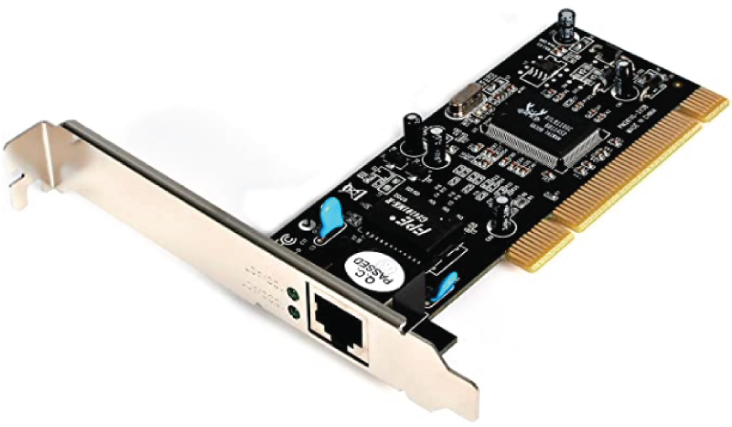
FIGURE 5.1 Network interface card
Nowadays, most PCs and laptops of all types come with an Ethernet and wireless connector built into the motherboard, so you usually don't need a separate card. It's rare to find a laptop today without a built-in wireless network card, but you can buy external wireless cards for desktops and laptops if you've got legacy equipment that needs them.
NICs today usually have one, two, or more LEDs; one, usually green, is called a link light, indicating that an Ethernet connection has been established with the device on the other end of the cable, and it flickers when traffic is being passed back or forth. The other, or others, usually indicates the speed of the connection: 10, 100, or 1000 Mbps. There's no universal standard for NIC LEDs, so check the manual to familiarize yourself with the ones you are working with. But it's not always that cut-and-dried that a blinking LED can mean the NIC is receiving a proper signal from the hub or switch; it can also indicate connectivity to and detection of a carrier on a segment. Another possibility is that it's found connectivity with a router or other end device using a crossover cable.
The other LED is aptly named the activity LED, and it tends to flicker constantly. That activity indicates the intermittent transmission and reception of frames arriving at the network or leaving it.
Hub
As you learned earlier, a hub is the device that connects all the segments of the network together in a star topology Ethernet network. As a hub has no intelligence, it is a layer 1 device. Each device in the network connects directly to the hub through a single cable and is used to connect multiple devices without segmenting a network. Any transmission received on one port will be sent out to all the other ports in the hub, including the receiving pair for the transmitting device, so that Carrier Sense Multiple Access with Collision Detection (CSMA/CD) on the transmitter can monitor for collisions.
So, basically, this means that if one station sends a broadcast, all the others will receive it; yet based on the addressing found in the frame, only the intended recipient will actually listen and process it. This arrangement simulates the physical bus that the CSMA/CD standard was based on, and it's why we call the use of a hub in an Ethernet environment a physical star/logical bus topology.
Figure 5.2 depicts a typical hub as you might find it employed within a small network. Since there are only two users, there isn't a problem in using a hub here. However, if there were 20 users, everyone would see Bob's request to send a packet to Sally. Most of the time, hubs really aren't recommended for corporate networks because of their limitations.
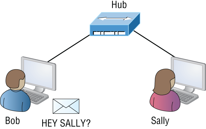
FIGURE 5.2 A typical hub
It's important to note that hubs are nothing more than glorified repeaters that are incapable of recognizing frames and data structures—the reason they act with such a lack of intelligence. A broadcast sent out by any device on the hub will be propagated to all devices connected to it. And just as in a physical bus topology configuration, any two or more of those connected devices have the potential of causing a collision with each other, which means that this hardware device will create a LAN with the most network traffic collisions. Hubs are not suggested for use in today's corporate network for this reason.
Bridge
A bridge—specifically, a transparent bridge—is a network device that connects two similar network segments together. Its primary function is to keep traffic separated on either side of the bridge, breaking up collision domains, as pictured in Figure 5.3.
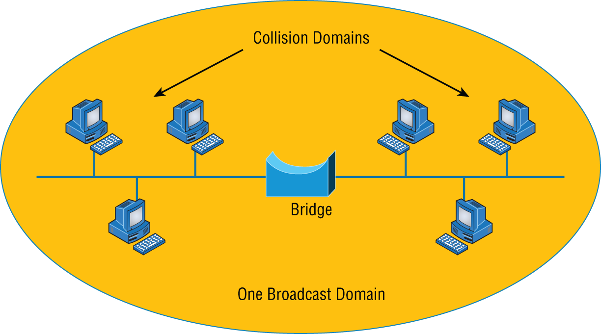
FIGURE 5.3 Bridges break up collision domains.
What we can see here is that traffic is allowed to pass through the bridge only if the transmission is intended for a station on the opposite side. The main reasons you would place a bridge in your network would be to connect two segments together or to divide a busy network into two segments. As bridges use MAC addresses to make forwarding decisions, they are considered layer 2 devices.
Bridges are software based, so, interestingly, you can think of a switch as a hardware-based, multiport bridge. In fact, the terms bridge and switch are often used interchangeably because the two devices used basically the same bridging technologies. The past tense is there for a reason—you'd be hard-pressed to buy a bridge today.
Switch
Switches connect multiple segments of a network together much like hubs do, but with three significant differences—a switch recognizes frames and pays attention to the source and destination MAC address of the incoming frame as well as the port on which it was received. A switch makes each of its ports a unique, singular collision domain. Hubs don't do those things. They simply send anything they receive on one port out to all the others. As switches use MAC addresses to make forwarding decisions, they are considered layer 2 devices.
So, if a switch determines that a frame's final destination happens to be on a segment that's connected via a different port than the one on which the frame was received, the switch will only forward the frame out from the specific port on which its destination is located. If the switch can't figure out the location of the frame's destination, it will flood the frame out of every port except the one on which the frame port was received.
Figure 5.4 shows a typical low-cost Ethernet switch. It looks a lot like a hub. However, switches can come in very large, expensive sizes. Switches that can perform the basic switching process and do not allow you to configure more advanced features—like adding an IP address for telnetting to the device or adding VLANs—are called unmanaged switches. Others, like Cisco switches that do allow an IP address to be configured for management with such applications as simple network management protocol (SNMP) and do allow special ports to be configured (as in VoIP), are called managed switches.
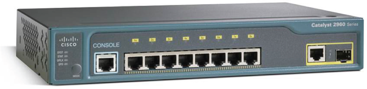
FIGURE 5.4 Typical Ethernet switch
That's as far as we're going with switches right now. I'll bring them up later on in this chapter and cover them in much greater detail in Chapter 11, “Switching and Virtual LANs.” For now, you can think of a switch as a faster, smarter bridge that has more ports.
Router
A router is a network device used to connect many, sometimes disparate, network segments together, combining them into what we call an internetwork. A well-configured router can make intelligent decisions about the best way to get network data to its destination. It gathers the information it needs to make these decisions based on a network's particular performance data. As routers use IP addresses to make forwarding decisions, they are considered layer 3 devices.
Figure 5.5 shows a small office, home office (SOHO) router that provides wired and wireless access for hosts and connects them to the Internet without any necessary configuration. But know that I certainly don't recommend leaving a router with the default configuration! No worries, though—I'll go over the configuration process with you in Chapter 10, “Routing Protocols.”
Routers can be multifaceted devices that behave like computers unto themselves with their own complex operating systems—for example, Cisco's IOS. You can even think of them as CPUs that are totally dedicated to the process of routing packets. And due to their complexity and flexibility, you can configure them to actually perform the functions of other types of network devices (like firewalls, for example) by simply implementing a specific feature within the router's software.
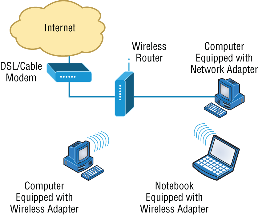
FIGURE 5.5 Router connected to the Internet, providing access for hosts
Interface Configurations
When configuring interfaces on a router or switch, unless you're doing complex configurations such as connecting up a Voice over IP (VoIP) network, the interface configurations are pretty straightforward.
There is a major difference between a router interface and a switch interface configuration, however. On a switch, you do not add an IP address since they only read to layer 2, and most of the time, you never even need to configure a switch interface. First, they are enabled by default, and second, they are very good at auto-detecting the speed, duplex, and, in newer switches, even the Ethernet cable type (crossover or straight-through). A router is much different and an IP address is expected on each interface; they are not enabled by default, and a good layer 3 network design must be considered before installing a router.
Let's start by taking a look at a basic Cisco switch configuration. First, notice by the output shown that there is no configuration on the interfaces, yet you can plug this switch into your network and it would work. This is because all ports are enabled and there are some very basic configurations that allow the switch to run without any configuration—they can be considered plug-and-play in a small or home network:
Switch#sh running-config[Some output cut for brevity]!interface FastEthernet0/1!interface FastEthernet0/2!interface FastEthernet0/3!interface FastEthernet0/4!interface FastEthernet0/5!interface FastEthernet0/6!interface FastEthernet0/7!interface FastEthernet0/8!
Let's take a look at a configuration of a simple switch interface. First, we'll notice the duplex options:
Switch(config-if)#duplex ?auto Enable AUTO duplex configurationfull Force full duplex operationhalf Force half-duplex operation
All switch ports are set to duplex auto by default, and usually you can just leave this configuration alone. However, be aware that if your network interface card is set to half-duplex and the switch port is configured for full-duplex, the port will receive errors and you'll eventually get a call from the user. This is why it is advised to just leave the defaults on your hosts and switch ports, but it is a troubleshooting spot to check when a problem is reported from a single user.
The next configuration and/or troubleshooting spot you may need to consider is the speed of the port:
Switch(config-if)#speed ?10 Force 10 Mbps operation100 Force 100 Mbps operation1000 Force 1000 Mbps operationauto Enable AUTO speed configuration
Again, this is set to auto, but you may want to force the port to be 1000 and full-duplex. Typically, the NIC will run this without a problem and you'll be sure you're getting the most bang for your buck on your switch port.
Let's take a look at a router interface. We're pretty much going to configure (or not configure) the same parameters. However, you should be very aware that a router interface and a switch interface perform different functions. A router interface will break up collision domains just as a switch interface does, but the purpose of a router interface is to create and maintain broadcast domains and connectivity of WAN services. Basic layer 2 switches cannot provide these services. As I mentioned, you must have a layer 3 design before you can implement a router, meaning you must have your subnet design laid out on your network diagram, and your IP addressing scheme must be completely understood. You cannot start configuring router interfaces randomly; there must be a design and it needs to be correct.
Unlike switches, router interfaces do not just work when you plug them into the network—they must be configured and enabled. All ports are shut down by default, and why shouldn't they be? Unless you have a network design and understand IP addressing, what good is a router to your network?
Let's take a look:
Router(config-if)#duplex ?auto Enable AUTO duplex configurationfull Force full duplex operationhalf Force half-duplex operationRouter(config-if)#speed ?10 Force 10 Mbps operation100 Force 100 Mbps operation1000 Force 1000 Mbps operationauto Enable AUTO speed configurationRouter(config-if)#ip address ?A.B.C.D IP addressdhcp IP Address negotiated via DHCPpool IP Address autoconfigured from a local DHCP pool
First, we can see that the basics are there, duplex and speed, but also, to make a router interface useful at all we must add an IP address. Notice that the options allow you to configure a specific IP address or allow the interface to receive the address from a DHCP server. You would only use this option if you had an IP address reservation for the router interface on your DHCP server because having your router get a random IP address from a DHCP server would be hard to manage. Let's finish the basics:
Router(config-if)#ip address 1.1.1.1 255.0.0.0Router(config-if)#no shutdownRouter(config-if)#*Oct 5 17:26:46.522: %LINK-3-UPDOWN: Interface FastEthernet0/0,changed state to up*Oct 5 17:26:47.522: %LINEPROTO-5-UPDOWN: Line protocol onInterface FastEthernet0/0, changed state to up
The interface can now be connected to a layer 2 switch and the hosts connected to the same broadcast domain must set their default gateway address to 1.1.1.1, and voilà, they can now send packets to the router.
Firewall
So what exactly is a firewall? Basically, firewalls are your network's security guards, and to be real, they're probably the most important thing to implement on your network. That's because today's networks are almost always connected to the Internet—a situation that makes security crucial! A firewall protects your LAN resources from invaders that prowl the Internet for unprotected networks while simultaneously preventing all or some of your LAN's computers from accessing certain services on the Internet. You can employ them to filter packets based on rules that you or the network administrator create and configure to strictly delimit the type of information allowed to flow in and out of the network's Internet connection. Firewalls operate at multiple layers of the OSI model. Some firewalls can operate up to the Application layer.
A firewall can be either a stand-alone “black box” or a software implementation placed on a server or router. Either way, the firewall will have at least two network connections: one to the Internet (known as the public side) and one to the network (known as the private side). Sometimes, there is a second firewall, as shown in Figure 5.6. This firewall is used to connect servers and equipment that can be considered both public and private (like web and email servers). This intermediary network is known as a screened subnet or, as it is often called, a demilitarized zone (DMZ).
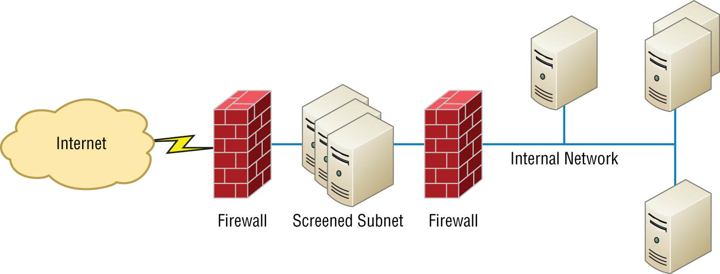
FIGURE 5.6 Example of firewalls with a screened subnet or DMZ
Firewalls are the first line of defense for an Internet-connected network. Without them in place, any network that's connected to the Internet is essentially wide open to anyone who is a little tech-savvy and seeks to exploit LAN resources or access your network's sensitive information.
In network security, a screened subnet refers to the use of one or more logical screening routers as a first defense on your network.
A typical firewall design can define three separate networks, or zones, to separate the external (untrusted) zone to a trusted (internal and DMZ) zone, also referred to as a perimeter network. Now, CompTIA likes to call this perimeter network a screened subnet or demilitarized zone (DMZ), where your DNS server and possibly HTTPS servers are.
IDS/IPS
Intrusion detection systems (IDSs) and intrusion prevention systems (IPSs) are very important in today's networks. They are network security appliances that monitor networks and packets for malicious activity. An IDS is considered to be monitor mode and just records problems and tells you about them, whereas an IPS can work in real time to stop threats as they occur.
The main difference between them is that an IPS works inline to actively prevent and block intrusions that are detected based on the rules you set up. IPSs can send an alarm, create correlation rules and remediation, drop malicious packets, provide malware protection, and reset the connection of offending source hosts.
HIDS
In a host-based IDS (HIDS), software runs on one computer to detect abnormalities on that system alone by monitoring applications, system logs, and event logs—not by directly monitoring network traffic.
Systems like these are typically implemented on servers because they're a bear to manage if spread across several client computers on a network. Plus, if the IDS database is on the local computer and its data becomes compromised by an attack, the IDS data could be corrupted, too.
Access Point
I'll be covering access points (APs) in depth in Chapter 12, “Wireless Networking,” but I'll introduce them here. Understand that an AP is just a hub that accepts wireless clients via an analog wireless signal. APs operate at layer 2.
It's no secret that wireless is the key to all networks in the world today, and wireless networks will be even more prevalent in the future when all our home appliances have IP addresses and communicate wirelessly to our networks, for example. The ease of communicating on a network using an AP instead of having to use an Ethernet cable has changed our world forever.
Figure 5.7 shows how an AP would look in a small network, such as a home.
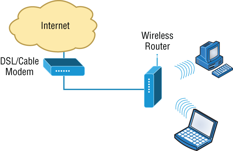
FIGURE 5.7 Example of an AP in a network
The wireless client modulates a digital signal to an analog signal, which the AP can read and demodulate back to a digital signal. The AP creates one collision domain and can only run half-duplex, which is why you can describe an AP as being like a hub. However, even though there are some standards that provide some full-duplex-type connectivity, a wireless host will never achieve the same type of throughput, security, and consistency that a wired Ethernet network would, but does that matter? Wireless is here to stay.
Wireless Range Extender
In some cases, you need the WLAN to extend further than the technology in use is designed to deliver. In that case, you can deploy what is called an extender. These are radios and antennas that operate in the same frequency or channel and receive the signal as a station would and then transmit it in the direction you desire to clients that are out of reach of the original AP.
These devices should be placed so there is at least 15 percent overlap of the coverage areas of the AP and the extender.
Wireless LAN Controller
In larger wireless networks it becomes an administrative burden to manage dozens, hundreds, or even thousands of wireless access points. This led to the design and deployment of a centralized Wi-Fi configuration controller known as a WLC, or wireless LAN controllers. The WLC lets you configure the complete network on a single device and push the configurations out to the Wi-Fi access points. The access points also tunnel the user data back to the controller, which then forwards the traffic onto the local area network (LAN).
WLCs greatly reduce the amount of administrative overhead required to manage large enterprise wireless networks.
Load Balancer
Your average router just sends incoming packets to their specified, correlative IP address on the network, but a load balancer can send incoming packets to multiple machines hidden behind one IP address—cool, right?
In large and busy networks, often a single server does not have the capabilities to serve all requested traffic. For example, a very busy website on the Internet could have hundreds of thousands of incoming requests every second. This if often too large for a single server to accommodate. Also, if that server were to fail, the whole website could go offline.
Load balancers solve this problem by publishing a virtual IP address to a domain to receive incoming traffic. The load balancer then has a pool of real servers that it distributes the connections to. The distribution can be based on round-robin, least number of connections, response time, a weighted percentage, or other metrics to evenly distribute the workload to the servers.
Health checks are performed to make sure that the servers are operational. If one does not respond, it can be automatically taken offline with the site still operating on the remaining servers.
Capacity can be dynamically added or removed using load balancers by using either manual or automatic scaling based on the current servers' workloads. New servers can dynamically be added and removed from the pool to scale the service up or down.
Today's load-balancing routers follow various rules to determine specifically how they will route network traffic. Depending on your needs, you can set rules based on the least load, fault tolerance, the fastest response times, or just dividing up (balancing) outbound requests for smooth network operations.
In fact, the fault tolerance, or redundancy, as well as the scalability so vital to large networking environments and e-commerce are some of the great benefits we gain using load balancers.
Think about this scenario: Say you have a website where people are placing orders for the stuff you've got for sale. Obviously, the orders placed vary in size, and the rate at which they come in varies; you definitely wouldn't want your servers becoming so overloaded that they hose up and crash your site, causing you to lose lots of money, now would you? That's where balancing the load of traffic between a group of servers comes to the rescue, because even if one of them freezes, your customers will still be able to access your site and place orders.
Contention Methods
In both wireless and wired environments that are shared mediums, meaning devices share a collision domain, such as when connected to a hub or when connected to a wireless access point, there is potential for frames from multiple devices colliding, destroying both packets. Both wired and wireless environments use a contention method to arbitrate access to the medium to help prevent collisions or at the least to recover from them when they occur. In the following sections, we'll look at the method used in each environment.
CSMA/CA
When the device sending the frame is transmitting onto a wireless network, the Carrier Sense Multiple Access with Collision Avoidance (CSMA/CA) contention method is used. The method starts with a check of the medium (in this case, a check of the radio frequency) for activity called physical carrier sense.
The frame will go to the AP. The AP will acknowledge reception of the frame. If the frame is destined for another wireless station located on this wireless LAN, the frame will be forwarded to it by the AP. When this occurs, the AP will follow the same CSMA/CA contention method to get the frame onto the wireless medium.
If the frame is destined for a station on the wired LAN, the AP will drop the 802.11 MAC header (which is structured differently from an Ethernet MAC header) and build a new Ethernet MAC header by using its MAC address as the source address and the MAC address of the default gateway as the destination. The LAN router will receive the frame, and normal LAN routing to the destination will continue from there, using the CSMA/CD contention mechanism (covered a bit later) to place the frame in the wire at each step. If frames are returned to the station, the AP will receive them, drop the Ethernet MAC header, build an 802.11 MAC header, and return the frame to the wireless station. When this occurs, the AP will follow the same CSMA/CA contention method to get the frame onto the wireless medium.
Describing CSMA/CA Operation
Because it is impossible for wireless stations to detect collisions, the CSMA/CA contention method is required to arbitrate access to the network. It requires a more involved process of checking for existing wireless traffic before a frame can be transmitted wirelessly. The stations (including the AP) must also acknowledge all frames. The steps in the process are as follows:
- Laptop A has a frame to send to laptop B. Before sending, laptop A must check for traffic in two ways. First, it performs carrier sense, which means it listens to see whether any radio waves are being received on its transmitter.
- If the channel is not clear (traffic is being transmitted), laptop A will decrement an internal countdown mechanism called the random back-off algorithm. This counter will have started counting down after the last time this station was allowed to transmit. All stations will be counting down their own individual timers. When a station's timer expires, it is allowed to send.
- If laptop A checks for carrier sense and there is no traffic and its timer hits zero, it will send the frame.
- The frame goes to the AP.
- The AP sends an acknowledgment back to laptop A. Until that acknowledgment is received by laptop A, all other stations must remain silent. The AP will cache the frame, where it already may have other cached frames that need to be relayed to other stations. Each frame that the AP needs to relay must wait its turn to send the frame using the same mechanism as the stations.
- When the frame's turn comes up in the cache queue, the frame from laptop A will be relayed to laptop B.
- Laptop B sends an acknowledgment back to the AP. Until that acknowledgment is received by the AP, all other stations must remain silent.
When you consider that this process has to occur for every single frame and that there are many other frame types used by the AP to manage other functions of the network that also create competition for air time, it is no wonder that actual throughput on a wireless LAN is at best about half the advertised rate.
For example, if two wireless stations were the only wireless clients and they were using 802.11g, which is capable of 56 Mbps, the very best throughput experienced would be about 25 to 28 Mbps. Moreover, as soon as a third station arrives, throughput will go down again because the stations are dividing the air time by 3 instead of 2. Add a fourth, and it gets even worse! Such is the challenge of achieving throughput on a wireless LAN.
CSMA/CD
When the device sending the frame is transmitting onto a wired network, the Carrier Sense Multiple Access with Collision Detection (CSMA/CD) contention method is used. This method is somewhat more efficient because it is possible for wired computers to detect collisions while wireless stations cannot. When a host's or router's interface needs to send a frame, it checks the wire, and if no traffic is detected, it sends without checking a random back-off timer.
However, it continues to listen, and if it detects that a collision has occurred, it sends out a jam signal that requires all stations to stop transmitting. Then the two computers that were involved in the collision will both wait a random amount of time (that each arrives at independently) and will resend. So instead of using a random break-off algorithm every time a transmission occurs, Ethernet uses its ability to detect collisions and uses this timer only when required, which makes the process more efficient.
Describing CSMA/CD Operation
CSMA/CD has mechanisms that help minimize but not eliminate collisions. Its operation is as follows:
- When a device needs to transmit, it checks the wire. If a transmission is already under way, the device can tell. This is called carrier sense.
- If the wire is clear, the device will transmit. Even as it is transmitting, it is performing carrier sense.
- If another host is sending simultaneously, there will be a collision. The collision is detected by both devices through carrier sense.
- Both devices will issue a jam signal to all the other devices, which indicates to them to not transmit.
- Then both devices will increment a retransmission counter. This is a cumulative total of the number of times this frame has been transmitted and a collision has occurred. There is a maximum number at which the device aborts the transmission of the frame.
- Both devices will calculate a random amount of time and will wait that amount of time before transmitting again. This calculation is called a random back-off.
- In most cases, because both devices choose random amounts of time to wait, another collision will not occur.
Dynamic Host Configuration Protocol Server
Even though I'm going to discuss the finer points of DHCP soon, in Chapter 6, “Introduction to the Internet Protocol,” I want to give you some basic insight into this server service here.
In essence, DHCP servers assign IP addresses to hosts. This protocol gives us a much easier way to administer—by automatically providing IP information—than the alternative and tedious method known as static IP addressing or static assignment, where we have to address each host manually. It works well in any network environment, from tiny to huge, and allows all types of hardware to be employed as a DHCP server, including routers.
It works like this: A DHCP server receives a request for IP information from a DHCP client using a broadcast (as Chapter 6 will show you in detail). The DHCP server is configured by the administrator with what is called a pool of addresses that it uses for this purpose. When the administrator configures this pool, they can also set some addresses in the pool as “off limits.” These are called IP exclusions or exclusion ranges. It means that these addresses cannot be assigned. An example might be the address of the router interface.
The only hitch is that if the DHCP server isn't on the same segment as the DHCP client, the broadcast won't be received by the server because by default, routers won't forward broadcasts, as shown in Figure 5.8.
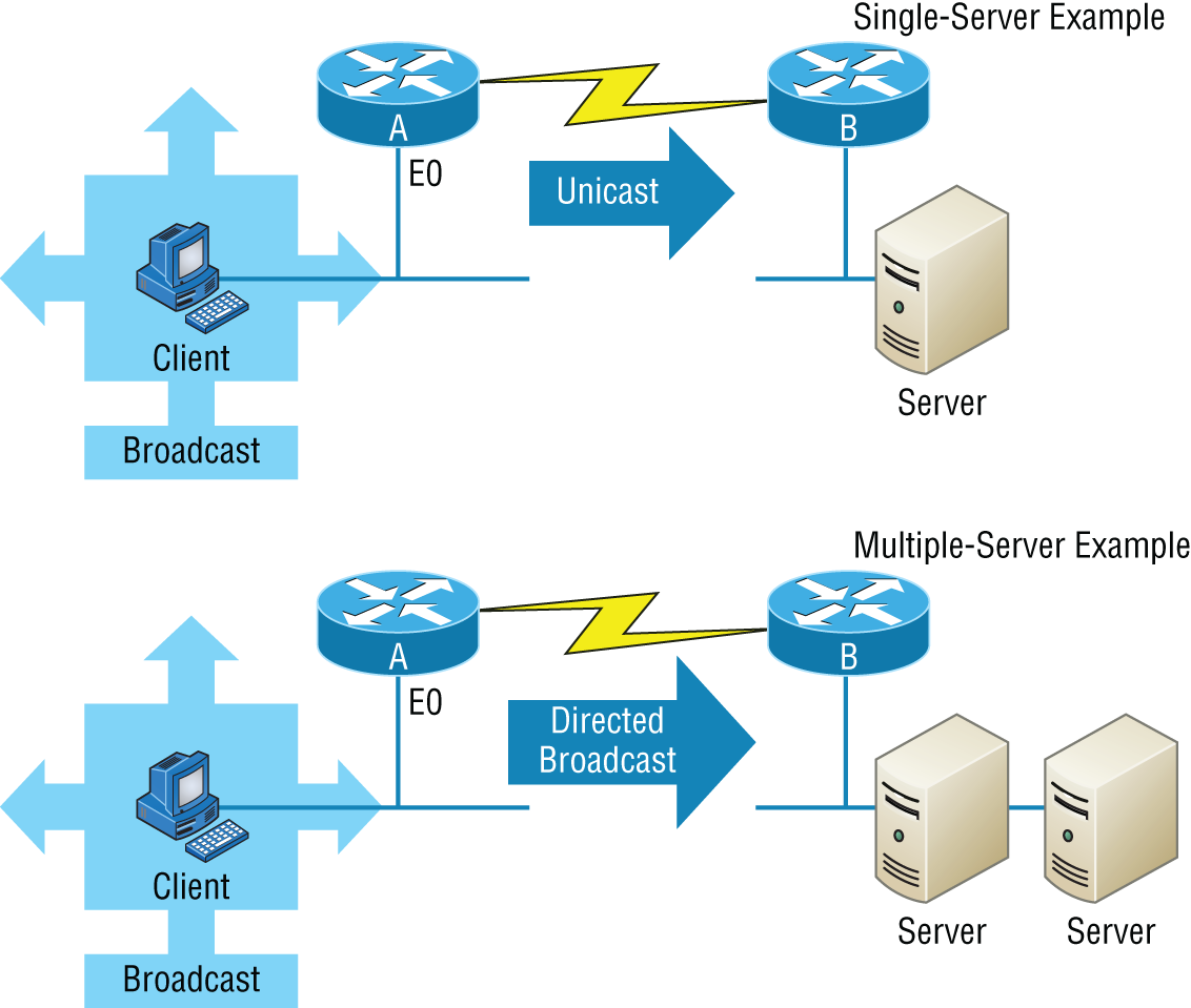
FIGURE 5.8 DHCP client sends broadcasts looking for a DHCP server.
In Figure 5.8, Router A is configured with the IP helper address command on interface E0 of the router. Whenever interface E0 receives a broadcast request, Router A will forward that request as a unicast (meaning instead of a broadcast, the packet now has the destination IP address of the DHCP server).
So, as shown in the figure, you can configure Router A to forward these requests and even use multiple DHCP servers for redundancy, if needed. This works because the router has been configured to forward the request to a single server using a unicast or by sending the request to multiple servers via a directed broadcast.
Personally, most of the time I use a Windows server to act as the DHCP server for my entire internetwork and have my routers forward client requests. It is possible to have a DHCP server on every network segment, but that is not necessary because of the routers' forwarding ability.
Figure 5.9 shows a Windows server with something called scope options.
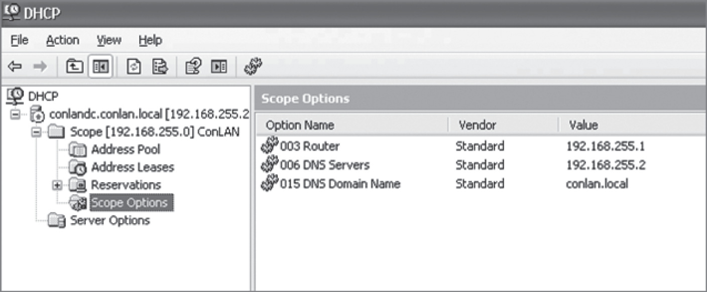
FIGURE 5.9 A Windows DHCP server's scope options
Scope options provide IP configuration for hosts on a specific subnet. Below Scope Options, you'll find Server Options; these options provide IP information for all scopes configured on the server. If I had just one Domain Name Service (DNS) server for the entire network, I'd configure the server options with my DNS server information; that DNS server information would then show up automatically in all scopes configured on my server.
So, what exactly does a DHCP client ask for, and what does a DHCP server provide? Is it just an IP address, a mask, and a default gateway? No, it is much more than that. Scope options comprise the informational elements that the DHCP server can provide to the DHCP clients. Here are some examples of these options:
- TTL (provides the default TCP TTL value for TCP packets sent by the client)
- DNS server
- TFTP server (especially important for IP phones that need to get a configuration for a TFTP server)
Let's take a look at a DHCP client request on an analyzer. Figure 5.10 shows the options that the client is requesting from the DHCP server.
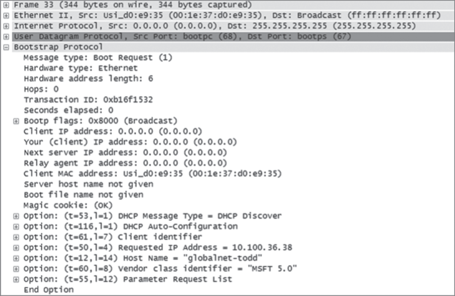
FIGURE 5.10 DHCP client request to a DHCP server
First, you can see that the DHCP service runs on top of the BootP protocol (port 68) and that the DHCP client is looking for a BootP server (port 67). The client IP address is 0.0.0.0, and the client doesn't know the DHCP server address either because this is a broadcast to 255.255.255.255 (the Data Link layer broadcast shows ff:ff:ff:ff:ff:ff). Basically, all the DHCP client knows for sure is its own MAC address. The client is “requesting” a certain IP address because this is the IP address it received from the server the last time it requested an IP address.
The DHCP client Parameter Request List option shown at the bottom of Figure 5.10 has been expanded and is shown in Figure 5.11. Notice all the parameter information that can be sent to a DHCP client from the server.
That is quite a request list! The DHCP server will respond with the options that it has configured and are available to provide to a DHCP client. Let's take a look and see what the server responds with. Figure 5.12 shows the DHCP server response.
The client is going to get the IP address that it asked for (10.100.36.38), a subnet mask of 255.255.255.224, a lease time of 23 hours (the amount of time before the IP address and other DHCP information expires on the client), the IP address of the DHCP server, the default gateway (router), the DNS server IP address (it gets two), the domain name used by DNS, and some NetBIOS information (used by Windows for name resolution).
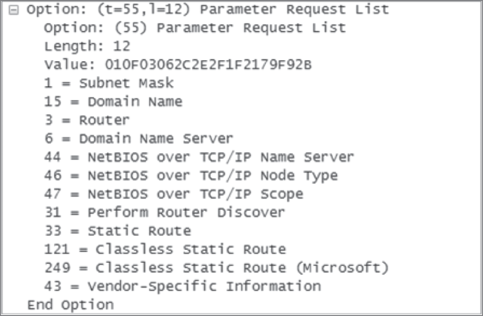
FIGURE 5.11 DHCP client parameter request list

FIGURE 5.12 DHCP server response
The lease time is important and can even be used to tell you if you have a DHCP problem or, more specifically, that the DHCP server is no longer handing out IP addresses to hosts. If hosts start failing to get onto the network one at a time as they try to get a new IP address as their lease time expires, you need to check your server settings.
Here is another example of a possible DHCP problem: You arrive at work after a weekend and find that some hosts were left on and some were shut down. The hosts that were left running and not shut down are still working, but the hosts that were shut down and were restarted on Monday morning do not get a new IP address. This is a good indication that you need to head over to your DHCP server and take a look at what is going on.
A DHCP server can also be configured with a reservation list so that a host always receives the same IP address. When this is done, the reservation is made on the basis of the router interface MAC address. Therefore, it is sometimes called a MAC reservation. You would use this reservation list for routers or servers if they were not statically assigned. However, you can use reservation lists for any host on your network as well.
DHCP is an Application layer protocol. While the DORA (Discover, Offer, Request, Acknowledgment) components operate at layer 2, the protocol is managed and responds to the Application layer. DHCP uses UDP ports 67 and 68.
DHCP Relay
If you need to provide addresses from a DHCP server to hosts that aren't on the same LAN as the DHCP server, you can configure your router interface to relay or forward the DHCP client requests, as shown in Figure 5.13. This is referred to as a DHCP relay. If we don't provide this service, our router would receive the DHCP client broadcast, promptly discard it, and the remote host would never receive an address—unless we added a DHCP server on every broadcast domain! Let's take a look at how we would typically configure DHCP service in today's networks.
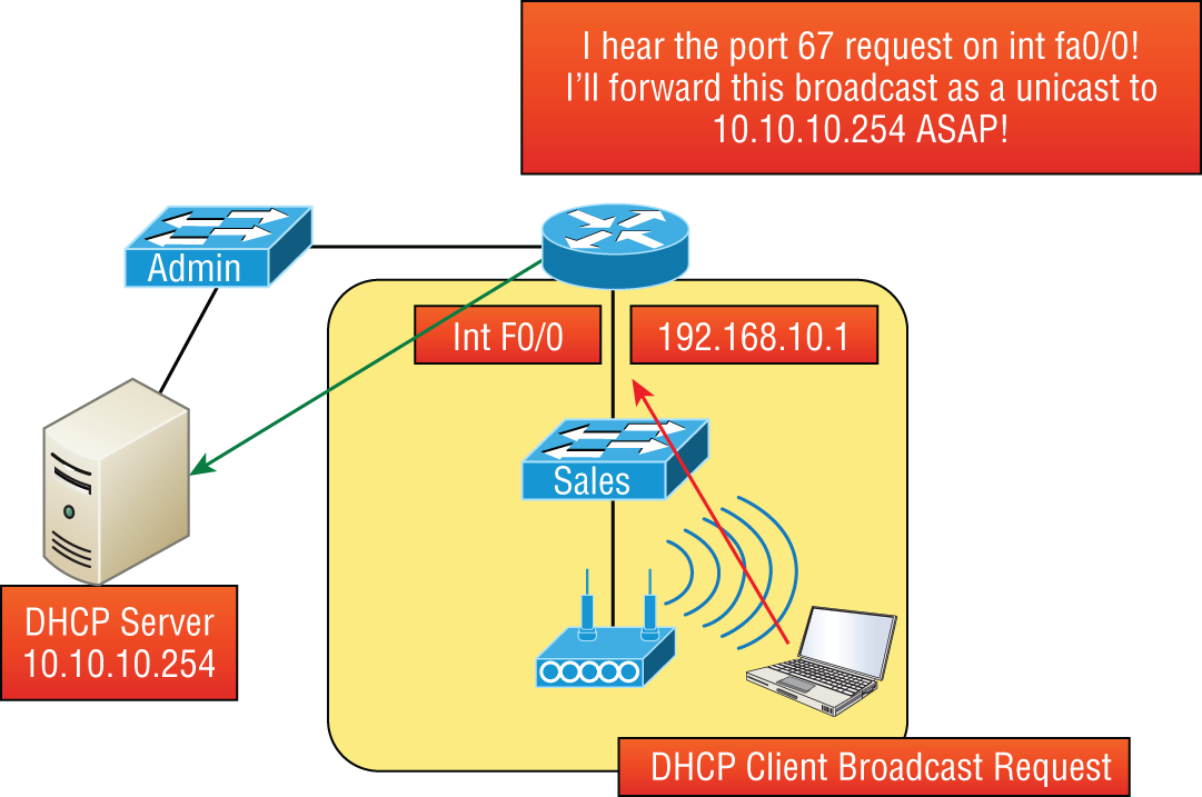
FIGURE 5.13 Configuring a DHCP relay
So we know that because the hosts off the router don't have access to a DHCP server, the router will simply drop their client request broadcast messages by default. To solve this problem, we can configure the F0/0 interface of the router to accept the DHCP client requests and forward them to the DHCP server like this:
Router#config tRouter(config)#interface fa0/0Router(config-if)#ip helper-address 10.10.10.254
Now I know that was a pretty simple example, and there are definitely other ways to configure the relay, but rest assured that I've covered the objectives for you. Also, I want you to know that
ip helper-address
forwards more than just DHCP client requests, so be sure to research this command before you implement it!
IPAM
IP address management (IPAM) tools are software products that integrate the management of DHCP and DNS. They are used to plan, track, and manage the IP addresses. With the integration of DNS ad DHCP, each process is kept abreast of changes made to the other service. Many products offer additional functionality as well, such as tracking of information such as which IP addresses are in use and the time, user, and devices for which an IP is assigned.
Other Specialized Devices
In addition to the network connectivity devices I've discussed, there are several devices that, while they may not be directly connected to a network, do actively participate in moving network data. Here's a list of them:
- Multilayer switch
- Domain Name Service server
- Network Time Protocol
- Proxy server
- Encryption devices
- Analog modem
- Packet shaper
- VPN concentrator headend
- Media converter
- VoIP PBX
- VoIP endpoint
- NGFW/layer 7 firewall
- VoIP gateway
- Cable modem
- DSL modem
Multilayer Switch
A multilayer switch (MLS) is a computer networking device that switches on Open Systems Interconnection (OSI) layer 2 like an ordinary network switch but provides routing. A 24-port MLS gives you the best of both worlds. It operates at layer 3 (routing) while still providing 24 collision domains, which a router could not do.
The major difference between the packet-switching operation of a router and that of a layer 3 or multilayer switch lies in the physical implementation. In routers, packet switching takes place using a microprocessor, whereas a layer 3 switch handles this by using application-specific integrated circuit (ASIC) hardware. I'd show you a picture of a layer 3 switch, but they look just like regular layer 2 switches and you already know what those look like. The differences are the hardware inside and the operating system.
Domain Name Service Server
A Domain Name Service (DNS) server is one of the most important servers in your network and on the Internet as well. Why? Because without a DNS server, you would have to type https://206.123.114.186 instead of simply entering www.lammle.com. So it follows that you can pretty much think of the DNS system as the phone book of the Internet.
A hostname is typically the name of a device that has a specific IP address; on the Internet, it is part of what is known as a fully qualified domain name (FQDN). An FQDN consists of a hostname and a domain name.
The process of finding the IP address for any given hostname is known as name resolution, and it can be performed in several ways: a hosts file (meaning you statically type in all names and IP addresses on each and every host), a request broadcast on the local network (Microsoft's favorite—why ask a server when you can just broadcast, right?), DNS, and Microsoft's Windows Internet Naming Service (WINS). DNS is the most popular today and is the resolution method you really need to know.
On the Internet, domains are arranged in a hierarchical tree structure. The following list includes some of the root or top-level domains currently in use:
.comA commercial organization. Most companies end up as part of this domain..eduAn educational establishment, such as a university..govA branch of the US government..intAn international organization, such as NATO or the United Nations..milA branch of the US military..netA network organization..orgA nonprofit organization.
Your local ISP is probably a member of the
.net
domain, and your company is probably part of the
.com
domain. The
.gov
and
.mil
domains are reserved strictly for use by the government and the military within the United States. In other parts of the world, the final part of a domain name represents the country in which the server is located (
.ca
for Canada,
.jp
for Japan,
.uk
for Great Britain, and
.ru
for Russia, for example). Well over 130 countries are represented on the Internet.
The
.com
domain is by far the largest, followed by the
.edu
domain. Some new domain names are becoming popular, however, because of the increasing number of domain-name requests. These include
.firm
for businesses and companies,
.store
for businesses selling goods rather than services,
.arts
for cultural and entertainment organizations, and
.info
for informational services. The domains
.cc
,
.biz
,
.travel
, and
.post
are also in use on the Internet.
Figure 5.14 shows how, when you type in a domain name, the DNS server resolves it, allowing the host to send the HTTPS packets to the server.
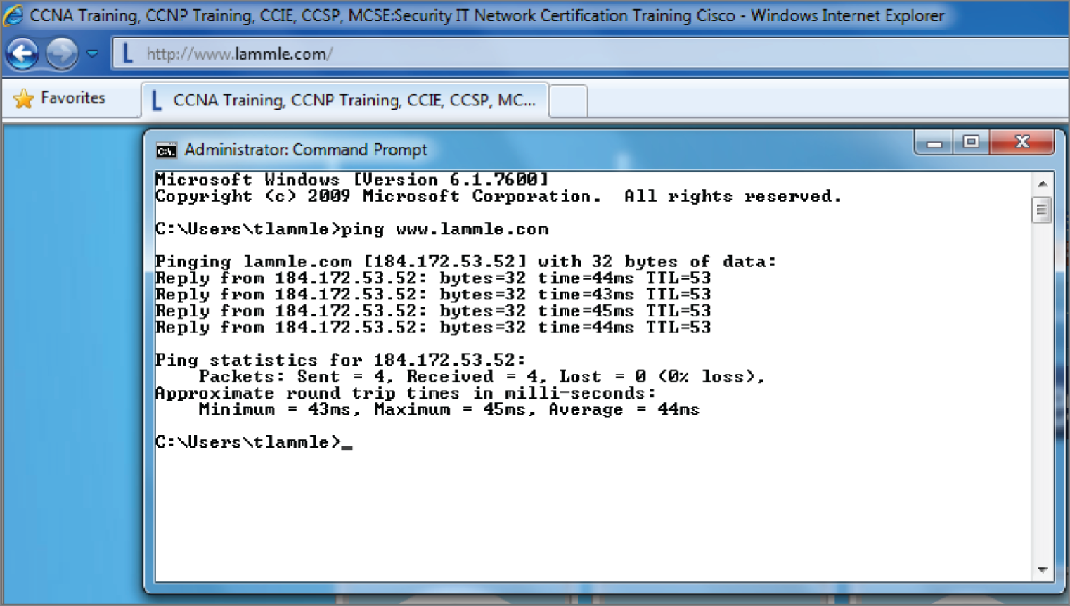
FIGURE 5.14 DNS resolution example
This Command Prompt screen shows how the DNS server can resolve the human name to the IP address of the Lammle.com server when I ping the server by the name instead of the IP address.
It should be easy to imagine how hard life would be without DNS translating human names to IP addresses, routing your packet through the Internet or internetwork to get to your servers. Figure 5.15 gives you an example of a Windows server configured as a DNS server.
To complete unqualified Domain Name Service (DNS) names that will be used to search and submit DNS queries at the client for resolution, you must have a list of DNS suffixes that can be appended to these DNS names. For DHCP clients, this can be set by assigning the DNS domain name option (option 15) and providing a single DNS suffix for the client to append and use in searches. For example, if you just wanted to ping todd instead of pinging todd.lammle.com, you can configure the DHCP server option 15 to provide the suffix for you.
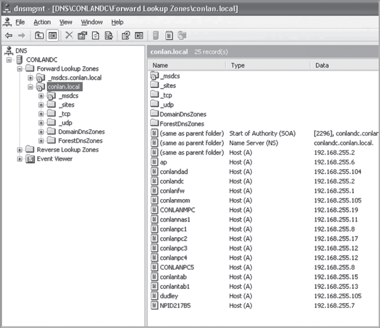
FIGURE 5.15 A Windows DNS server
Now the hosts can receive the IP address of this DNS server, and then this server will resolve hostnames to correct IP addresses. This is a mission-critical service in today's networks, don't you think? As shown in Figure 5.15, if I ping from a host to
conlanpc1
, the host will send the name-resolution request to the DNS server and translate this name to IP address 192.168.255.8.
Host (A) is called an A record or address (A) record and is what gives you the IP address of a domain or host. In IPv6, it's called a quad-A or AAAA record. In Figure 5.15, you can see that each name has an A record, which is associated to an IP address. So, A records resolve hostnames to IP addresses, but what happens if you know the IP address and want to know the hostname? There is a record for this, too! It's called the pointer record (PTR).
Another typical type of record found on DNS servers is the mail exchanger (MX) record, which is used to translate mail records. The MX record points to the mail exchanger for a particular host. DNS is structured so that you can actually specify several mail exchangers for one host. This feature provides a higher probability that email will arrive at its intended destination. The mail exchangers are listed in order in the record, with a priority code that indicates the order in which they should be accessed by other mail-delivery systems.
There are many types of records the DNS server keeps as, shown in Table 5.1.
TABLE 5.1 Additional DNS record types
| Record Type | Explanation |
|---|---|
| A | Address record returns the IP address of the domain. |
| AAAA | Used to map hostnames to an IPv6 address of the host. |
| TXT (SPF) | The text record specifies a list of authorized hostnames/IP addresses that mail can originate from for a given domain name. |
| TXT (DKIM) | Domain Keys Identified Mail is used to provide authentication of mail sent and received by the same email system and is used to prevent spam. |
| SRV | DNS service or generalized service location record. Specifies a port number in addition to the IP address. |
| CAA | Certificate Authority Authorization allows domain name owners to specify authorized certificate authorities. |
| CNAME | Canonical name records are used to alias one domain name to another such as toddlammle.com to Lammle.com. |
| SOA | Start of authority provides administrative information about the domain or zone such as the email of the administrator, when the domain was last updated, and time intervals such as refresh and time to live. |
| PTR | The pointer record used for reverse DNS lookup, which returns the domain name when given the IP address. |
| MX | Mail exchanger record specifies how email messages should be routed. |
| NS | Name server represents the authoritative DNS server for the domain. |
If the first-priority mail exchanger doesn't respond in a given amount of time, the mail-delivery system tries the second one, and so on. Here are some sample mail-exchange records:
hostname.company.com. IN MX 10 mail.company.com.hostname.company.com. IN MX 20 mail2.company.com.hostname.company.com. IN MX 30 mail3.company.com.
In this example, if the first mail exchanger, mail.company.com, does not respond, the second one, mail2.company.com, is tried, and so on.
Another important record type on a DNS server is the canonical name (CNAME) record. This is also commonly known as the alias record, and it allows hosts to have more than one name. For example, suppose your web server has the hostname www and you want that machine to also have the name ftp so that users can use FTP to access a different portion of the file system as an FTP root. You can accomplish this with a CNAME record. Given that you already have an address record established for the hostname www, a CNAME record that adds ftp as a hostname would look something like this:
www.company.com. IN A 204.176.47.2ftp.company.com. IN CNAME www.company.com.
When you put all these record types together in a zone file, or DNS table, it might look like this:
mail.company.com. IN A 204.176.47.9mail2.company.com. IN A 204.176.47.21mail3.company.com. IN A 204.176.47.89yourhost.company.com. IN MX 10 mail.company.com.yourhost.company.com. IN MX 20 mail2.company.com.yourhost.company.com. IN MX 30 mail3.company.com.www.company.com. IN A 204.176.47.2ftp.company.com. IN CNAME www.company.com.
DNS uses zone transfers from the primary DNS server for a zone to update standby servers, this allows us to have some redundancy in our DNS deployments and distribute the workload across multiple DNS servers.
When a client gets a DNS reply from a query, it will store it locally (cached) for a period of time to reduce the number of lookups on the DNS servers. In each DNS reply there is a field called TTL, or time to live. This instructs the client how long to store the replay before requesting again. This allows us to reduce the network workload and keep the DNS data fresh on the client. All devices use a cache system that stores the requests locally for a period of time and the time to live (TTL) value tells the client how long that should be.
What if you know the IP address but want to know what the domain name is? DNS can perform reverse lookup to query the server with the IP address and it will return the domain name. Other lookup types include recursive and iterative. When a DNS system uses a recursive lookup, one DNS server will query other DNS servers instead of the client performing all of the operations. The other option is to have the client communicate with multiple DNS servers during the name resolution process and it's referred to as an iterative DNS query.
Finally, there are other record types you should know about such as AAAA (for authentication IPV6 host addresses), PTR (pointer) records, and SOA (start of authority) records. PTR records are IP address–to–name mapping records rather than name–to–IP address mapping records. They reside in what is called a reverse lookup zone (or table) in the server and are used when an IP address is known but not a name. The start of authority (SOA) record stores information about the DNS domain or zone such as how to contact the administrator, when the domain was last updated, and how long the server should wait between refreshes.
Let's take a better look at how resolution takes place between a host and a DNS server. Figure 5.16 shows a DNS query from my host to www.lammle.com from a browser.
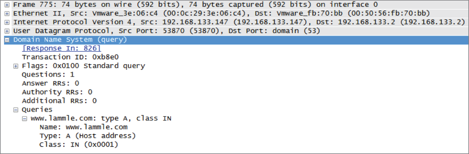
FIGURE 5.16 A DNS query to www.lammle.com
This figure shows that DNS uses User Datagram Protocol (UDP) at the Transport layer (it uses Transport Control Protocol [TCP] if it is updating its phone book pages—we call these zone updates), and this query is asking destination port 53 (the DNS service) on host 192.168.133.2 who the heck www.lammle.com is.
Let's take a look at the server's response. Figure 5.17 shows the DNS answer to our query for www.lammle.com.
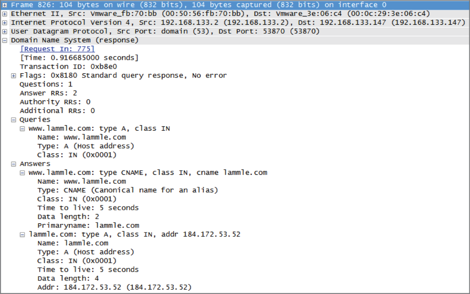
FIGURE 5.17 The DNS answer to our query
Port 53 answered from server 192.168.133.147 with a CNAME and an A record with the IP address of 184.172.53.52. My host can now go to that server requesting HTTP pages using the IP address.
DNS is an Application layer protocol. DNS queries are made on UDP port 53.
Dynamic DNS
At one time all DNS records had to be manually entered into the DNS server and edited manually when changes occurred. Today, DNS is dynamic. It uses dynamic assignment and works in concert with the DHCP function. Hosts register their names with the DNS server as they receive their IP address configuration from the DHCP server. Some older operating systems are not capable of self-registration, but the DHCP server can even be configured to perform registration on behalf of these clients with the DNS server.
This doesn't mean that manual records cannot be created if desired. In fact, some of the record types we have discussed can only be created manually. These include MX and CNAME records.
Internal and External DNS
DNS servers can be located in the screened subnet (or DMZ) or inside the intranet, as shown in Figure 5.18.
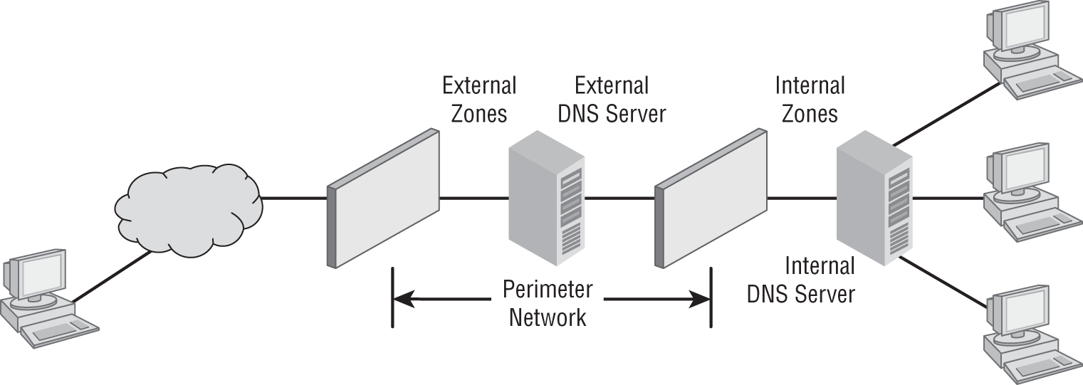
FIGURE 5.18 Internal and external DNS
When located in the DMZ, the DNS server should only contain the records of the devices that are placed in the DMZ. Implementing separate internal and external DNS servers might require you to include external resource records in the internal DNS zone. You need to do this when the Active Directory forest root uses the same DNS domain name as the external network or when you want to reference the externally accessible resources by their true IP addresses in the perimeter network rather than using the addresses published to the Internet by the firewall protecting the perimeter network.
Third-Party/Cloud-Hosted DNS
Some smaller organizations find that it makes more sense to outsource the DNS function. Rather than hire and train staff to set up, configure, and maintain the infrastructure required to keep name resolution up and secure, they might find it more cost effective to utilize a third party who make it their business to provide this service. There is no shortage of cloud providers falling all over themselves to provide you with cloud-based storage, and these same vendors stand ready to provide you with DNS as a service, and they'll probably do a better job at it than you will.
Network Time Protocol
The Network Time Protocol (NTP) provides the time synchronization of the clocks on networking devices and computers on a network. This is used for distributed tasks that require accurate time to make sure tasks are processed in the correct sequence and recorded properly. NTP is needed for security and log tracking across many devices to correlate and trace events based on time. Many network management applications rely on timestamps for performance measurements and troubleshooting. If all of the devices in a network did not have the same time provided by syncing to a master clock using NTP, these would not be possible.
- Stratum stratum level indicates how accurate the time source is. If the primary reference clock is a master time source such as a nuclear clock or a satellite navigation array, it is considered to be stratum level 0. Stratum 1 takes its time source from a stratum 0 clock and stratum 2 syncs from stratum 1 and so on. The accuracy is less the further you are from a stratum 0 time source.
- Clients Clients use the NTP protocol to query NTP servers to set their clocks. If every device in a network uses NTP, then all the clocks will be synchronized.
Once a client has synchronized its clock from an NTP time server, it will generally check every 10 minutes to keep its time updated.
- Servers NTP servers can be specialized hardware on your network that sync to stratum 0 devices or on the Internet. The site at
https://tf.nist.gov/tf-cgi/servers.cgilists servers available for public use.
Proxy Server
A proxy server is basically a type of server that handles its client-machine requests by forwarding them on to other servers while allowing granular control over the traffic between the local LAN and the Internet. When it receives a request, the proxy will then connect to the specific server that can fulfill the request for the client that wants it. A proxy server operates at the Application layer.
Sometimes the proxy modifies the client's request or a server's response to it—or even handles the client's request itself. It will actually cache, or “remember,” the specific server that would have normally been contacted for the request in case it's needed another time. This behavior really speeds up the network's function, thereby optimizing its performance. However, proxy servers can also limit the availability of the types of sites that users on a LAN have access to, which is a benefit for an administrator of the network if users are constantly connected to non-work sites and using all the WAN bandwidth.
Figure 5.19 shows where a proxy server would be typically found in a small-to-medium network.
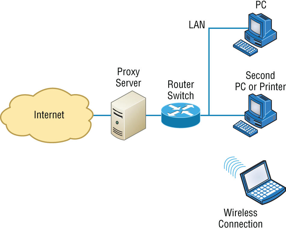
FIGURE 5.19 A proxy server
There are two main types of proxy servers you'll typically find working in present-day networks:
- Web Proxy Server A web proxy server is usually used to create a web cache. You experience this when you google a site you've visited before. The web proxy “remembers” you, and the site not only loads faster, it sometimes even recalls your personal information by automatically filling in your username—or even your billing/shipping information when you place another order.
- Caching Proxy Server A caching proxy server speeds up the network's service requests by recovering information from a client's earlier request. Caching proxies keep local copies of the resources requested often, which really helps minimize the upstream use of bandwidth. These servers can greatly enhance network performance.
I want to mention one more thing before we move on from proxies, and this is reverse proxies. Unlike a forward proxy, a reverse proxy takes requests from the Internet and forwards them to servers in an internal network, whereas the forward proxy we discussed in this section takes client requests and sends them to the Internet.
Encryption and Content Filtering
Although a number of the devices we have discussed earlier can perform encryption services, there are dedicated appliances that can perform encryption as well. The advantage of using these devices is that they normally provide more choice of encryption methods and stronger encryption options. They also offload the process from other devices like routers and servers, which is a good thing since the encryption/decryption process is very processor intensive and interferes with other functions that those routers and servers might be performing.
Sometimes these devices are called encryption gateways. They can either sit in line with a server or a local network, encrypting and decrypting all traffic, or function as an application server, encrypting any file sent to them within a network. Examples of encryption appliances are shown in Figure 5.20.
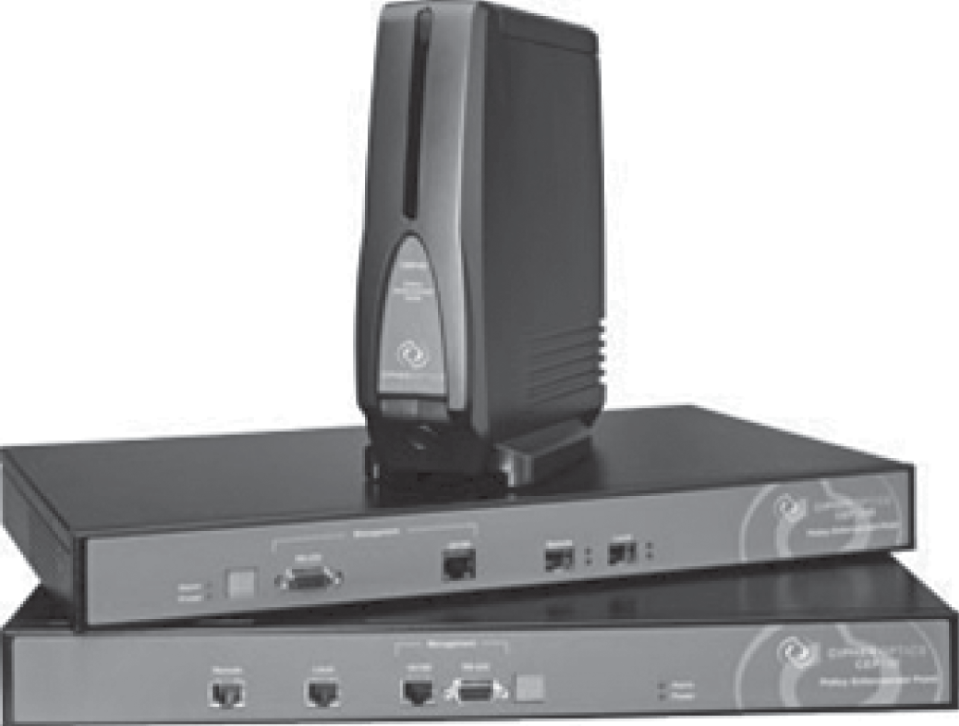
FIGURE 5.20 Encryption appliances
While an encryption appliance is dedicated to encryption, a content filtering appliance scans the content of what goes through it and filters out specific content or content types. Dedicating a device to this process offloads the work from servers or routers that could do this but at a cost of greatly slowing the devices. Also, there is usually more functionality and granular control available with a dedicated appliance.
Email is a good example of what you might run through one of these devices to filter out spam and objectionable content before the email is delivered. Another example of the use of a content filter might be to block websites based on the content of the web pages rather than on the basis of the URL or IP address. An example of a dedicated content/URL filtering appliance from SecPoint is shown in Figure 5.21.
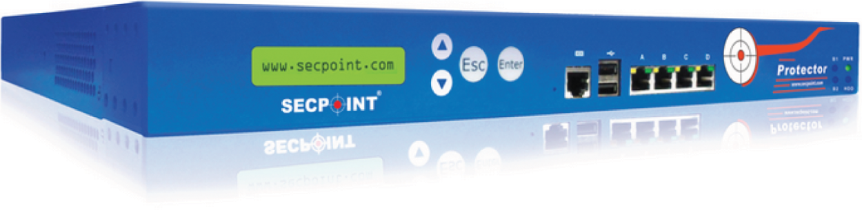
FIGURE 5.21 Content filtering appliance
Analog Modem
A modem (modulator-demodulator) is a device that modulates an analog carrier signal to encode digital information and demodulates the signal to decode the transmitted information. I gave you an example of this when I explained APs earlier in the chapter because an AP modulates and demodulates a signal just like a modem. Figure 5.22 shows a current analog modem that can be used in today's networks, albeit with slow throughput.
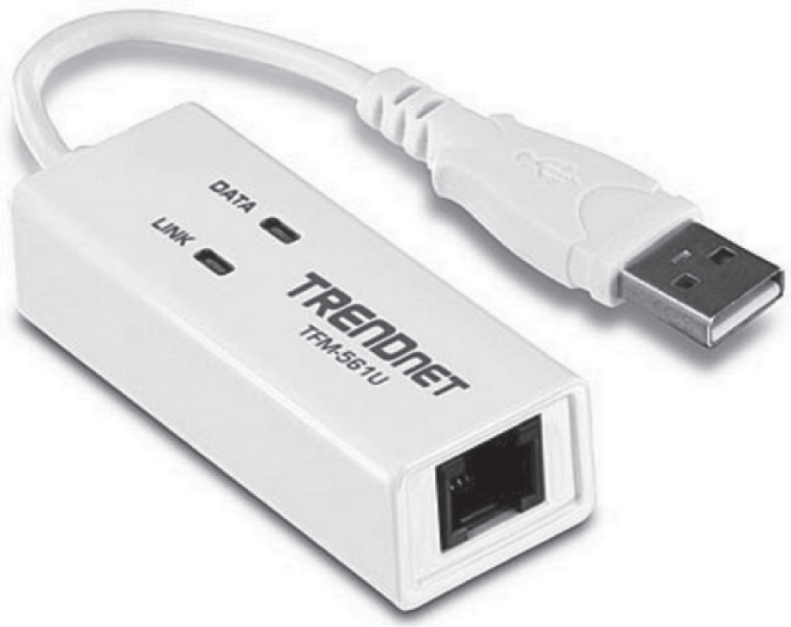
FIGURE 5.22 Analog modem
The goal is to produce a signal that can be transmitted easily and decoded to reproduce the original digital data. These signals are transmitted over telephone lines and demodulated by another modem at the receiver side in order to read the digital data.
Because modems connect to phone lines, the location and installation of these devices is fairly cut-and-dried. It will have to be near a phone line, with one end connected to the phone line and another to a computer or modem bank. The analog modem operates at layer 1, like a repeater.
Packet Shaper
Packet shaping (also known as traffic shaping, it's a form of rate limiting) is an Internetworking traffic management technique that delays some or all packets to bring them into compliance with your or your company's traffic profile. Figure 5.23 shows a dedicated packet shaper appliance from Blue Coat.
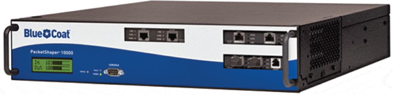
FIGURE 5.23 Packet shaper
This process is used to optimize or guarantee performance, improve latency, and/or increase usable bandwidth for some kinds of packets by delaying other kinds, decided on by you.
VPN Concentrator/Headend
A VPN concentrator, or as it is often called, a headend, is a device that accepts multiple VPN connections from remote locations. Although this function can be performed by a router or server, as with the encryption gateways and content filtering devices discussed earlier, the same performance benefits can be derived from dedicating a device to this. Moreover, additional functionality usually comes with these devices, one of which is shown in Figure 5.24.
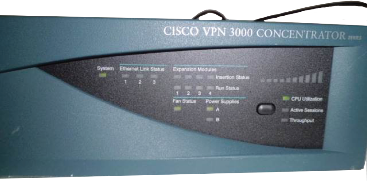
FIGURE 5.24 VPN headend
A headend device is a central control device required by some networks (for example, LANs or MANs). A headend device can also refer to a central control device within CATV systems that provides centralized functions such as re-modulation.
Media Converter
Media converters are used when you need to convert from one type of cabling to another type. This might be required to convert from one type of fiber to another or from Ethernet to fiber, for example. Figure 5.25 shows an Ethernet-to-fiber conversion box. Obviously, the location of these devices depends on where the conversion needs to take place. Media converters operate at layer 1.
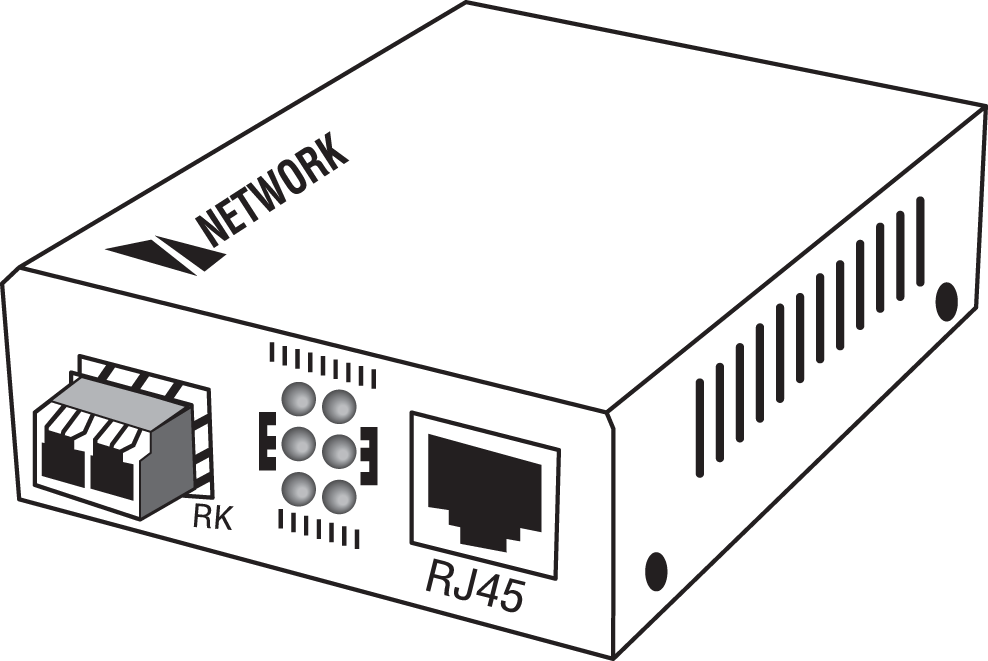
FIGURE 5.25 Media converter
VoIP PBX
A private branch exchange (PBX) is a private telephone switch that resides on the customer premises. It has a direct connection to the telecommunication provider's switch. It performs call routing within the internal phone system. This is how a company can have two “outside” lines but 50 internal phones. The call comes in on one of the two outside lines, and the PBX routes it to the proper extension. Sometimes the system converts analog to digital but not always.
A VoIP PBX is one that switches calls between VoIP (Voice over Internet Protocol, or IP) users on local lines while allowing all users to share a certain number of external phone lines. The typical IP PBX can also switch calls between a VoIP user and a traditional telephone user or between two traditional telephone users in the same way that a conventional PBX does.
VoIP Endpoint
VoIP endpoints are desktop phone systems or wireless phone systems that are part of the converged networks where data and voice traffic are now combined in today's networks. These endpoints may also be implemented as conferencing systems in meeting rooms. There is more flexibility and freedom in the location and installation of these systems as more wireless modes of connectivity are introduced for these devices.
NGFW/Layer 7 Firewall
Next-generation firewalls (NGFWs) are a category of devices that attempt to address traffic inspection and application awareness shortcomings of a traditional stateful firewall without hampering the performance. Although unified threat management (UTM) devices also attempt to address these issues, they tend to use separate internal engines to perform individual security functions. This means a packet may be examined several times by different engines to determine whether it should be allowed into the network.
NGFWs are application aware, which means they can distinguish between specific applications instead of allowing all traffic coming in via typical web ports. Moreover, they examine packets only once during the deep packet inspection phase (which is required to detect malware and anomalies).
VoIP Gateway
A VoIP gateway (Voice over IP gateway) is a network device that helps to convert voice and fax calls between an IP network and public switched telephone network (PSTN) in real time. A VoIP gateway can typically support at least two T1/E1 digital channels. Most VoIP gateways feature at least one Ethernet and telephone port. Various protocols, such as MGCP, SIP, and LTP, can help to control a gateway.
Cable Modem
The cable modem allows for voice, video, and data (usually Internet) to connect from a home or small business to a cable provider's network. The cable modem is installed at the customer site and connects to the coax (coaxial) cable network. The Data Over Cable Service Interface Specifications (DOCSIS) standard allows both voice and data to share the cable with the standard video TV offerings provided by the local cable company.
DSL Modem
Digital Subscriber Line (DSL) modems are commonly deployed by traditional phone companies that have twisted-pair copper as the local connection to homes and businesses. DSL modems allow for voice, video, and data (usually Internet) to piggyback on the local copper line as a high-frequency carrier above the standard voice frequencies.
Networked Devices
The field of networking is constantly evolving and moving forward. In the good old days networks usually only connected desktop computers to servers and printers. In today's world, almost everything is being networked. As a network engineer you must be aware of these devices and their requirements.
VoIP Phones
As you learned earlier in this chapter, phones have migrated from the older analog style to digital Ethernet. While they tend to be low bandwidth, they are sensitive to delay and jitter so some form of quality of service (QoS) is usually required on the network to make sure the voice quality is acceptable.
Printers
Instead of having a printer connected to each desktop, they can be shared on the network with NIC cards installed directly in the printer or by using a print server that connects to the Ethernet network and to the printer using a serial or parallel connection.
Physical Access Control Devices
In modern office buildings and industrial sites, access control systems are installed at key points such as a door or a gate. These devices are connected to an authorization server on the network, which can connect back to directory services such as Microsoft Active Directory. When a user scans their badge, a lookup is performed by the server and a response is sent back to the access control device to either unlock the door or prevent the person from entering.
Cameras
Cameras have moved from the analog world to digital and are now very common in today's networks. They operate off TCP/IP and send video feeds back to a central server for processing and recording. Advanced features may include Pan/Tilt/Zoom (PTZ) to remotely control the camera and detection capabilities such as facial recognition are now common. Some cameras have heat and metal sensing capabilities.
Heating, Ventilation, and Air Conditioning (HVAC) Sensors
Modern office buildings and industrial sites have intelligent HVAC systems that use sensors to monitor and control air conditioning and heating systems. This allows them to either manually or automatically adjust the environmental controls and has the added advantage of cost saving by changing the temperature values after hours when no one is in the facility.
Internet of Things (IoT)
The number of devices connected to the Internet has exploded in the past few years and only shows signs of increasing to numbers in the billions of devices.
Wearable devices such as watches, fitness analyzers, and medical sensors are driving this growth. At home we now have digital assistants such as Siri and Alexa that connect to digital doorbells, refrigerators, thermostats, lights, cameras, televisions, and speakers.
This is collectively known as the Internet of Things (IoT) and the number and types of things is constantly increasing as new products and applications are introduced.
We see IoT devices everywhere, including weather monitoring stations, traffic control devices, security devices, and devices for an almost infinite number of other uses. They connect to the network using what connectivity options are available at their locations. Common network connections include Ethernet, Wi-Fi, Bluetooth, and cellular. IoT devices connect to centralized server applications and usually consume very little network bandwidth. However, if there are a very large number of IoT devices, the additive bandwidth may become significant.
Industrial Control Systems
The industrial control systems (ICS) technology space uses sensors for monitoring and control of everything from power grids to machines on the factory floor. By monitoring machinery, companies can proactively detect problems and flag the device for maintenance, potentially saving money on repairs and downtime. Other uses are to monitor assembly line workflows and dynamically change them based on workload.
The supervisory control and data acquisition (SCADA) architecture is an industry standard for monitoring and collecting industrial data such as a power grid or water utility.
SCADA systems consist of an architecture that includes computers, sensors, and networks that collect and display the status of the monitored systems in a graphical format. SCADA systems are used to monitor electrical or water systems, industrial plants, and machinery. The monitored systems use programmable logic controllers (PLCs) or other types of sensors such as flow or electrical meters to interface with the machinery or systems.
Planning and Implementing a Basic SOHO Network Using Network Segmentation
It's likely that at some point you'll have to break up one large network into a bunch of smaller ones because user response will have dwindled to a slow crawl as the network grew and grew. With all that growth, your LAN's traffic congestion will have reached epic proportions.
Determining Requirements
When implementing a SOHO network, the first thing is to identify the requirements of the network and the constraints around which you must operate. This should drive your design and device choices. An example set of requirements and constraints might be as follows:
- A small number of computers are needed.
- There is a high need for Internet access.
- Resources need to be shared.
- Wired hosts and wireless hosts will need to communicate with each other.
- Security is very important.
With these constraints in mind, you might find that you'll need more than just a switch and some Ethernet cabling for this project. There is a need for a router, an AP, and a firewall in this case. In addition, you need to think about compatibility between equipment and the types and brands of equipment to buy as well as environmental issues or limitations.
One of the most important considerations you must take very seriously when building a basic network is LAN traffic congestion, which can be lessened with network segmentation and is directly related to device types and compatibility requirements as well as equipment limitations. Let's look at how to use the segmentation devices I have defined so far in this chapter.
Here's a list of some of the nasty things that commonly cause LAN traffic congestion:
- Too many hosts in a broadcast domain
- Broadcast storms
- Multicasting
- Low bandwidth
- Adding hubs for connectivity to the network
The answer to fixing a huge but slow network is to break it up into a number of smaller networks—something called network segmentation. You do this by using devices like routers and switches, which are sometimes still referred to as bridges because switches still use bridging technologies. Figure 5.26 displays a network that's been segmented with a switch so each network segment connected to the switch is now a separate collision domain. But make note of the fact that this network is actually still one broadcast domain—the set of all devices on a network segment that hear all the broadcasts sent on that segment.
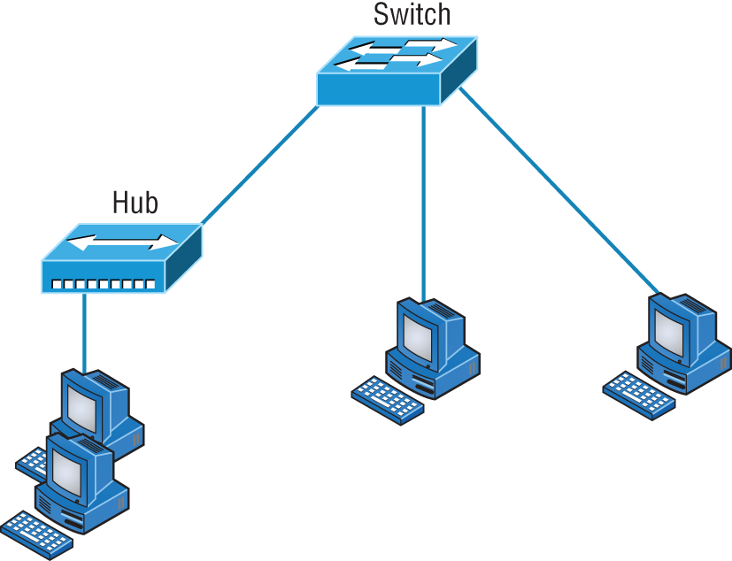
FIGURE 5.26 A switch can replace the hub, breaking up collision domains.
And keep in mind that the hub used in Figure 5.26 just extended the one collision domain from the switch port.
Routers are used to connect networks together and route packets of data from one network to another. (Cisco has become the de facto standard for routers because of its high-quality router products, great selection, and fantastic service.) Routers, by default, break up a broadcast domain. Figure 5.27 shows a router in our little network that creates an internetwork and breaks up broadcast domains.
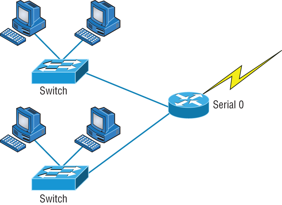
FIGURE 5.27 Routers create an internetwork.
The network in Figure 5.27 is pretty cool. Each host is connected to its own collision domain, and the router has created two broadcast domains. And don't forget that the router provides connections to WAN services as well. The router uses something called a serial interface for WAN connections: specifically, a V.35 physical interface.
Breaking up a broadcast domain is important because when a host or server sends a network broadcast, every device on the network must read and process that broadcast—unless you've got a router. When the router's interface receives this broadcast, it can respond by basically saying, “Thanks, but no thanks,” and discard the broadcast without forwarding it on to other networks. Even though routers are known for breaking up broadcast domains by default, it's important to remember that they break up collision domains as well.
There are two advantages of using routers in your network:
- They don't forward broadcasts by default.
- They can filter the network based on layer 3 (Network layer) information (such as an IP address).
Four router functions in your network can be listed as follows:
- Packet switching
- Packet filtering
- Internetwork communication
- Path selection
Remember that routers are really switches; they're actually what we call layer 3 switches. Unlike layer 2 switches, which forward or filter frames, routers (layer 3 switches) use logical addressing and provide what is called packet switching. Routers can also provide packet filtering by using access lists, and when routers connect two or more networks together and use logical addressing (IP or IPv6), this is called an internetwork. Last, routers use a routing table (map of the internetwork) to make path selections and to forward packets to remote networks.
Conversely, switches aren't used to create internetworks (they do not break up broadcast domains by default); they're employed to add functionality to a network LAN. The main purpose of a switch is to make a LAN work better—to optimize its performance—providing more bandwidth for the LAN's users. And switches don't forward packets to other networks as routers do. Instead, they only “switch” frames from one port to another within the switched network.
By default, switches break up collision domains, as mentioned in Chapter 4, “The Current Ethernet Specifications.” Collision domain is an Ethernet term used to describe a network scenario wherein one particular device sends a packet on a network segment, forcing every other device on that same segment to pay attention to it. At the same time, a different device tries to transmit, leading to a collision, after which both devices must retransmit, one at a time. Not very efficient! This situation is typically found in a hub environment where each host segment connects to a hub that represents only one collision domain and only one broadcast domain. By contrast, each and every port on a switch represents its own collision domain.
The term bridging was introduced before routers and hubs were implemented, so it's pretty common to hear people referring to bridges as switches. That's because bridges and switches basically do the same thing—break up collision domains on a LAN. (In reality, you cannot buy a physical bridge these days, only LAN switches, but these switches use bridging technologies.)
So this means a switch is basically just a multiple-port bridge with more brainpower, right? Well, pretty much, but there are differences. Switches do provide this function, but they do so with greatly enhanced management ability and features. Plus, most of the time, bridges only had two or four ports. Yes, you could get your hands on a bridge with up to 16 ports, but that's nothing compared to the hundreds available on some switches.
Figure 5.28 shows how a network would look with all these internetwork devices in place. Remember that the router will not only break up broadcast domains for every LAN interface but also break up collision domains.
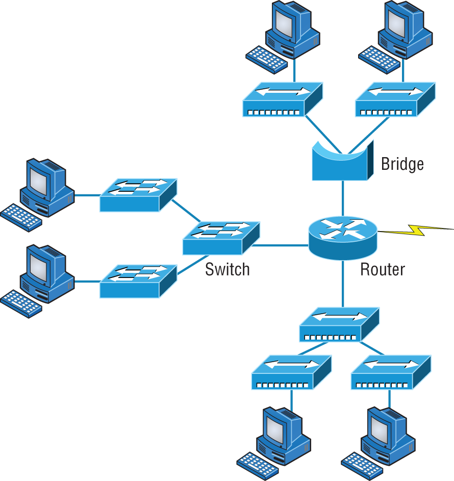
FIGURE 5.28 Internetworking devices
When you look at Figure 5.28, do you see the router at center stage and see how it connects each physical network together? We have to use this layout because of the older technologies involved—bridges and hubs.
On the top internetwork in Figure 5.28, you'll notice that a bridge is used to connect the hubs to a router. The bridge breaks up collision domains, but all the hosts connected to both hubs are still crammed into the same broadcast domain. Also, the bridge creates only two collision domains, so each device connected to a hub is in the same collision domain as every other device connected to that same hub. This is actually pretty lame, but it's still better than having one collision domain for all hosts.
Notice something else: The three hubs at the bottom that are connected also connect to the router, creating one collision domain and one broadcast domain. This makes the bridged network look much better indeed.
The best network connected to the router is the LAN switch network on the left. Why? Because each port on that switch breaks up collision domains. But it's not all good—all devices are still in the same broadcast domain. Do you remember why this can be a really bad thing? Because all devices must listen to all broadcasts transmitted, that's why. And if your broadcast domains are too large, the users have less bandwidth and are required to process more broadcasts, and network response time will slow to a level that could cause office riots.
Once we have only switches in our network, things change a lot. Figure 5.29 shows the network that is typically found today.
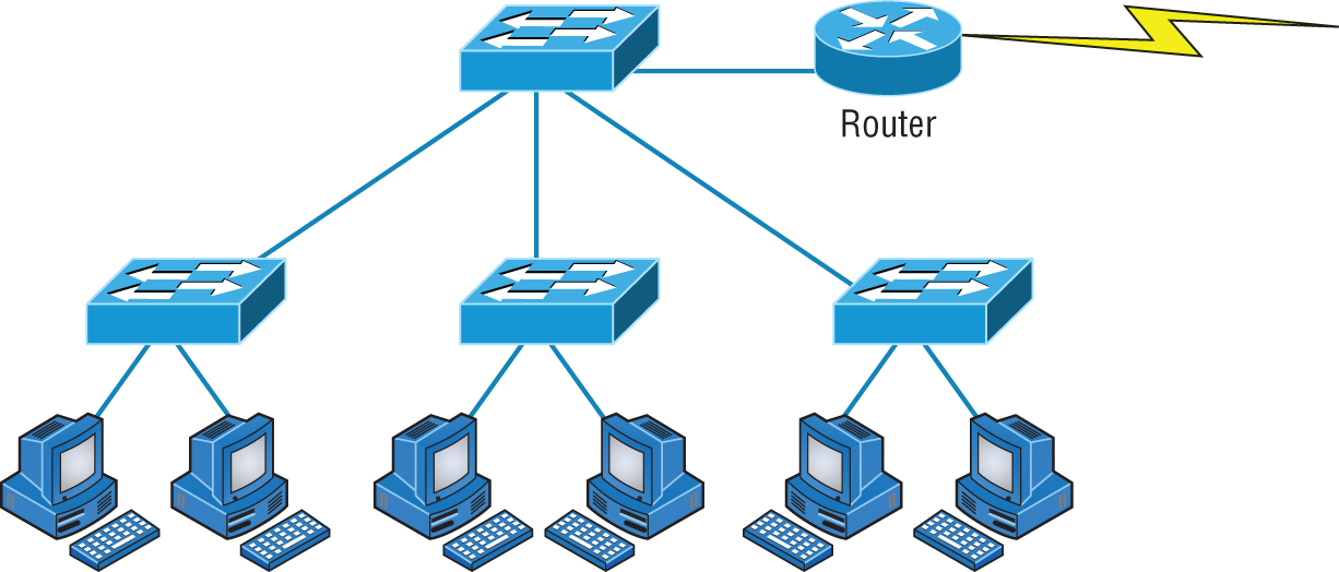
FIGURE 5.29 Switched networks creating an internetwork
Here I've placed the LAN switches at the center of the network world so the router is connecting only logical networks together. If I implement this kind of setup, I've created virtual LANs (VLANs), something I'm going to tell you about in Chapter 11, “Switching and Virtual LANs”. So don't stress. But it is really important to understand that even though you have a switched network, you still need a router to provide your inter-VLAN communication, or internetworking. Don't forget that.
Obviously, the best network is one that's correctly configured to meet the business requirements of the company it serves. LAN switches with routers, correctly placed in the network, are the best network design. This book will help you understand the basics of routers and switches so you can make tight, informed decisions on a case-by-case basis.
Let's go back to Figure 5.28 again. Looking at the figure, how many collision domains and broadcast domains are in this internetwork? I hope you answered nine collision domains and three broadcast domains.
The broadcast domains are definitely the easiest to see because only routers break up broadcast domains by default. And because there are three connections, that gives you three broadcast domains. But do you see the nine collision domains? Just in case that's a no, I'll explain. The all-hub network is one collision domain; the bridge network equals three collision domains. Add in the switch network of five collision domains—one for each switch port—and you've got a total of nine.
Now, in Figure 5.29, each port on the switch is a separate collision domain and each VLAN is a separate broadcast domain. But you still need a router for routing between VLANs. How many collision domains do you see here? I'm counting 10—remember that connections between the switches are considered collision domains.
So now that you've gotten an introduction to internetworking and the various devices that live in an internetwork, it's time to head into internetworking models.
As I mentioned earlier, routers break up broadcast domains, which means that by default, broadcasts aren't forwarded through a router. Do you remember why this is a good thing? Routers break up collision domains, but you can also do that using layer 2 (Data Link layer) switches. Because each interface in a router represents a separate network, it must be assigned unique network identification numbers, and each host on the network connected to that router must use the same network number. Figure 5.30 shows how a router works in an internetwork.
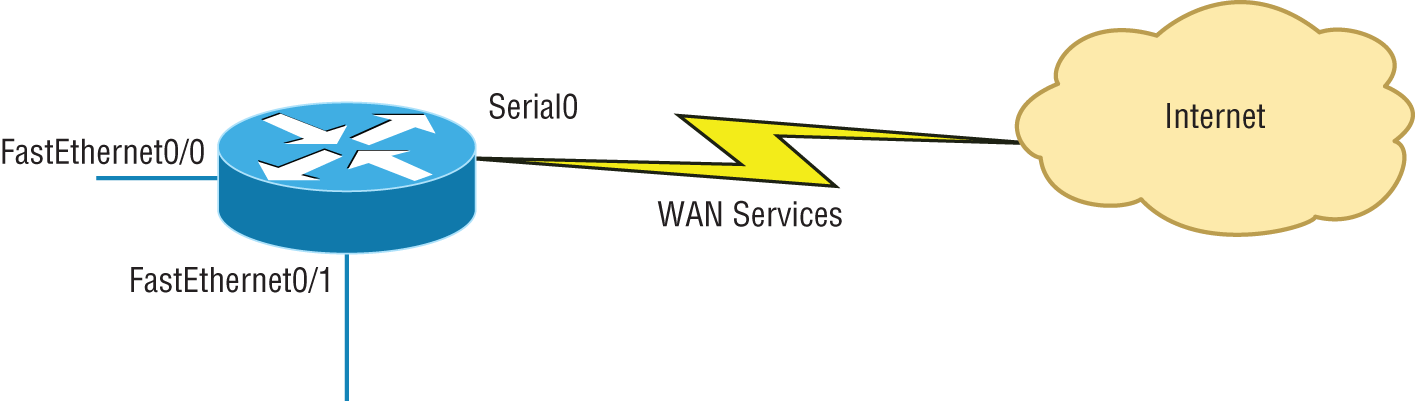
FIGURE 5.30 A router in an internetwork
Here are some points about routers that you should commit to memory:
- Routers, by default, will not forward any broadcast or multicast packets.
- Routers use the logical address in a Network layer header to determine the next hop router to forward the packet to.
- Routers can use access lists, created by an administrator, to control security on the types of packets that are allowed to enter or exit an interface.
- Routers can provide layer 2 bridging functions if needed and can simultaneously route through the same interface.
- Layer 3 devices (routers, in this case) provide connections between virtual LANs (VLANs).
- Routers can provide quality of service (QoS) for specific types of network traffic.
Switches and Bridges at the Data Link Layer
Layer 2 switching is considered hardware-based bridging because it uses specialized hardware called an application-specific integrated circuit (ASIC). ASICs can run up to multi-gigabit speeds with very low latency rates.
Bridges and switches read each frame as it passes through the network. The layer 2 device then puts the source hardware address in a filter table and keeps track of which port the frame was received on. This information (logged in the bridge's or switch's filter table) is what helps the machine determine the location of the specific sending device. Figure 5.31 shows a switch in an internetwork.
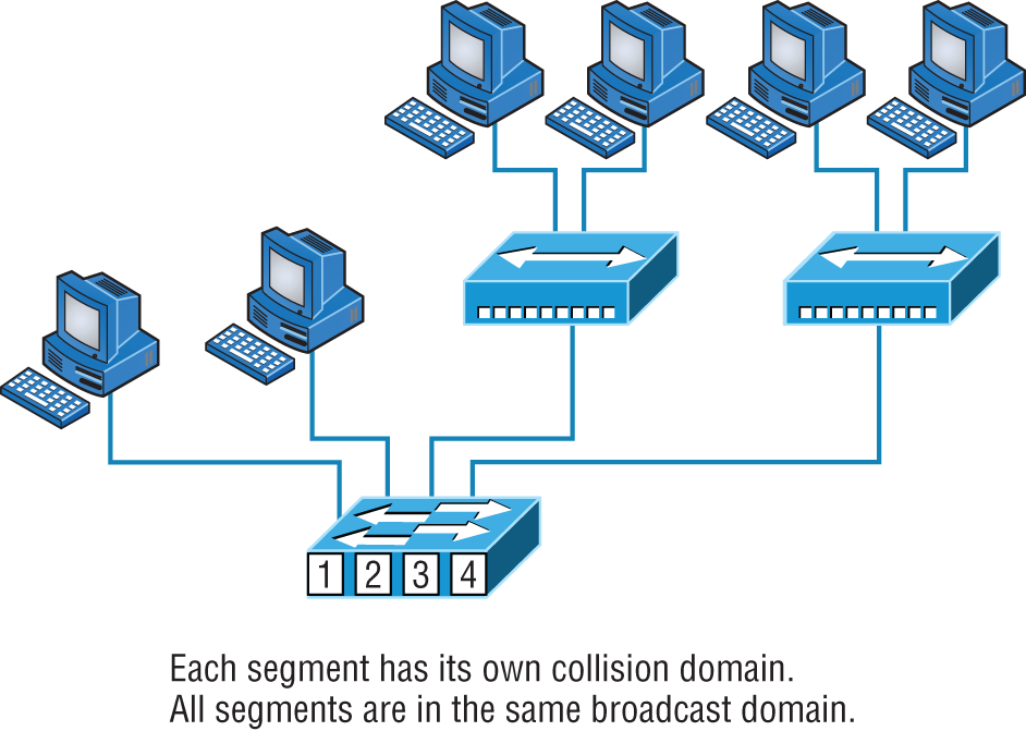
FIGURE 5.31 A switch in an internetwork
The real estate business is all about location, location, location, and it's the same way for both layer 2 and layer 3 devices. Although both need to be able to negotiate the network, it's crucial to remember that they're concerned with very different parts of it. Primarily, layer 3 machines (such as routers) need to locate specific networks, whereas layer 2 machines (switches and bridges) need to eventually locate specific devices. So, networks are to routers as individual devices are to switches and bridges. And routing tables that “map” the internetwork are for routers as filter tables that “map” individual devices are for switches and bridges.
After a filter table is built on the layer 2 device, it will forward frames only to the segment where the destination hardware address is located. If the destination device is on the same segment as the frame, the layer 2 device will block the frame from going to any other segments. If the destination is on a different segment, the frame can be transmitted only to that segment. This is called transparent bridging.
When a switch interface receives a frame with a destination hardware address that isn't found in the device's filter table, it will forward the frame to all connected segments. If the unknown device that was sent the “mystery frame” replies to this forwarding action, the switch updates its filter table regarding that device's location. But in the event that the destination address of the transmitting frame is a broadcast address, the switch will forward all broadcasts to every connected segment by default.
All devices that the broadcast is forwarded to are considered to be in the same broadcast domain. This can be a problem. Layer 2 devices propagate layer 2 broadcast storms that choke performance, and the only way to stop a broadcast storm from propagating through an internetwork is with a layer 3 device—a router.
The biggest benefit of using switches instead of hubs in your internetwork is that each switch port is actually its own collision domain. (Conversely, a hub creates one large collision domain.) But even armed with a switch, you still can't break up broadcast domains. Neither switches nor bridges will do that. They'll typically simply forward all broadcasts instead.
Another benefit of LAN switching over hub-centered implementations is that each device on every segment plugged into a switch can transmit simultaneously—at least they can as long as there is only one host on each port and a hub isn't plugged into a switch port. As you might have guessed, hubs allow only one device per network segment to communicate at a time.
Hubs at the Physical Layer
As you know, a hub is really a multiple-port repeater. A repeater receives a digital signal, reamplifies or regenerates that signal, and then forwards the digital signal out all active ports without looking at any data. An active hub does the same thing. Any digital signal received from a segment on a hub port is regenerated or reamplified and transmitted out all ports on the hub. This means all devices plugged into a hub are in the same collision domain as well as in the same broadcast domain. Figure 5.32 shows a hub in a network.
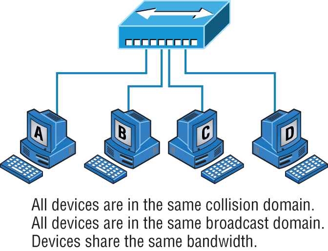
FIGURE 5.32 A hub in a network
Hubs, like repeaters, don't examine any of the traffic as it enters and is then transmitted out to the other parts of the physical media. Every device connected to the hub, or hubs, must listen if a device transmits. A physical star network—where the hub is a central device and cables extend in all directions out from it—is the type of topology a hub creates. Visually, the design really does resemble a star, whereas Ethernet networks run a logical bus topology, meaning that the signal has to run through the network from end to end.
Environmental Considerations
All of the equipment discussed in this chapter—switches, routers, hubs, and so on—require proper environmental conditions to operate correctly. These devices have the same needs as any computing device. The environmental concerns can be categorized as follows:
- Temperature Like any device with a CPU, infrastructure devices such as routers, switches, and specialty appliances must have a cool area to operate. When temperatures rise, servers start rebooting and appliance CPUs start overworking as well. The room(s) where these devices are located should be provided with heavy-duty HVAC systems and ample ventilation. It may even be advisable to dedicate a suite for this purpose and put the entire system on a UPS with a backup generator in the case of a loss of power.
Modern data centers use the architecture of hot and cold isles. This maximizes the cooling of the equipment racks by forcing cold air in one row of racks and the exhaust of the hot air exiting into the next row.
- Humidity The air around these systems can be neither too damp nor too dry; it must be “just right.” If it is too dry, static electricity will build up in the air, making the situation ripe for damaging a system. It takes very little static electricity to fry some electrical components. If it is too damp, connections start corroding and shorts begin to occur. A humidifying system should be used to maintain the level above 50 percent. The air conditioning should keep it within acceptable levels on the upper end.
Summary
Whew, this chapter covered quite a bit of information. You learned the difference between a router, a switch (bridge), and a hub and when to use each one. I also covered some devices that you might find in a network today, but not as often, such as VPN concentrators and content filters.
The information I discussed about DNS and DHCP is critical to your success on the Network + exam, and I highly suggest that you reread those sections. I covered how both the DNS and DHCP services work on a network.
In addition to the most common devices, I discussed the specialized network devices mentioned in the Network + objectives. I finished the chapter by discussing environmental conditions.
All of the information in this chapter is fundamental, and you must understand it before moving on to the other chapters in this book.
Exam Essentials
Understand how DHCP works and its purpose. Dynamic Host Configuration Protocol (DHCP) provides IP configuration information to hosts. It is important to know how a DHCP client requests information from a server, how a server receives this information, and also how the server responds to the client and with what type of information.
Understand how DNS works and its purpose. Domain Name Service (DNS) is used to resolve human names to IP addresses. Understanding how DNS resolves these names is critical, as is understanding how a DNS query is sent and how a DNS server responds. Know the different types of DNS records and what they are used for.
Understand the difference between a hub, a switch (bridge), and a router A hub just connects network segments together. A switch/bridge segments the network using MAC addresses, and a router segments the network using logical addressing (IP and IPv6). Switches break up collision domains, and routers break up broadcast domains by default.
Remember the different names for a router. A router is a layer 3 hardware device, but it can also be called a layer 3 switch or a multilayer switch.
Remember the various devices used on networks today and when you would use each one and how. Understand the differences and how each device works: routers, switches, hubs, DNS servers, and DHCP servers.
Identify the purpose, benefits, and characteristics of using a proxy service. A proxy server keeps a LAN somewhat separated from the Internet. Doing so increases security and filtering control and has the tendency to speed up Internet access through caching of recently used web pages.
Describe the proper use of network segmentation when planning and implementing a basic SOHO network. Understand and apply the concepts of proper network segmentation when planning the use of various devices in the design of a SOHO network.
Describe the benefits of using a network load balancer Network load balancers allow incoming connections to be spread out across multiple servers for scalability and resiliency. Understand the architecture of how load balancers are inserted into a network
Describe the benefits of using dedicated appliances for certain services. Using appliances to offload functions such as encryption, content filtering, and VPN concentrators can decrease the workload of other systems and add functionality that may be present in these dedicated devices.
Also, wireless LAN controllers let you configure the complete network on a single device and push the configurations out to the Wi-Fi access points. The access points also tunnel the user data back to the controller, which then forwards the traffic onto the Local Area Network (LAN).
Lastly, NTP servers provide accurate date and time information to servers and networking equipment.
Identify the environmental requirements of infrastructure devices. A cool temperature, ample ventilation, and the proper humidity level are all key to maintaining the operation of devices like routers, switches, and appliances.
Written Lab
Complete the table by filling in the appropriate layer of the OSI or hub, switch, or router device. You can find the answers in Appendix A.
| Description | Device or OSI layer |
|---|---|
| This device sends and receives information about the Network layer. | |
| This layer creates a virtual circuit before transmitting between two end stations. | |
| A layer 3 switch or multilayer switch. | |
| This device uses hardware addresses to filter a network. | |
| Ethernet is defined at these layers. | |
| This layer supports flow control and sequencing. | |
| This device can measure the distance to a remote network. | |
| Logical addressing is used at this layer. | |
| Hardware addresses are defined at this layer. | |
| This device creates one big collision domain and one large broadcast domain. | |
| This device creates many smaller collision domains, but the network is still one large broadcast domain. | |
| This device can never run full-duplex. | |
| This device breaks up collision domains and broadcast domains. |
Review Questions
You can find the answers to the review questions in Appendix B.
- Which of the following is not a term used when making SOHO Internet connections?
- Hub
- Router
- NIC
- Switch
- IDS/IPS
- What advantage does a switch have over a hub?
- It discards frames.
- Transmissions received on one port will be sent out all the other ports.
- It recognizes frame boundaries and destination MAC addresses of incoming frames.
- Any two or more devices the switch connects are capable of causing a collision with each other.
- Which device is used to segment a network?
- Hub
- Switch
- Repeater
- All of the above
- What is the primary function of a bridge?
- Breaks up collision domains
- Allows a NIC or other networking device to connect to a different type of media than it was designed for
- Allows mobile users to connect to a wired network wirelessly
- None of the above
- A network device that is used to connect multiple devices together without segmenting a network is a ___________________.
- Hub
- Wireless access point
- Switch
- Router
- Which of the following is among the benefits of a switch?
- Protects LAN resources from attackers on the Internet
- Provides extra bandwidth
- Reduces throughput
- Allows access to all computers on a LAN
- Which of the following devices can work at both layers 2 and 3 of the OSI model?
- Hub
- Switch
- Multilayer switch
- Bridge
- What is an advantage of using DHCP in a network environment?
- More difficult administration of the network
- Static IP addressing
- Can send an operating system for the PC to boot from
- Assigns IP address to hosts
- What is a benefit of a multilayer switch (MLS) over a layer 2 switch?
- Less bandwidth
- Routing functions
- Fewer features
- Fewer ports
- Which device should be used if you need to send incoming packets to one or more machines that are hidden behind a single IP address?
- Switch
- Load balancer
- Hub
- Repeater
- What role does the A record in a Domain Name Service (DNS) server have in your network?
- Translates human name to IP address
- Translates IP address to human name
- Enables printing, copying, and faxing from one device
- Controls network packets to optimize performance
- Which device does not aid in network segmentation?
- Router
- Switch
- Hub
- Bridge
- What is the most common use for a web proxy?
- Web cache
- Throughput increase
- DHCP services
- Support for user authentication
- Which is not an advantage of network segmentation?
- Reducing congestion
- Improving security
- Containing network problems
- Preventing broadcast storms
- Users arrive at the office after a weekend and the hosts that were shut down over the weekend are restarted but cannot access the LAN or Internet. Hosts that were not shut down are working fine. Where can the problem be?
- The DNS server
- The DHCP server
- The proxy server
- The firewall
- You need a device that can prevent your users from accessing certain websites. Which device should you install?
- Firewall
- IDS
- IPS
- Proxy server
- Which device creates separate collision domains and a single broadcast domain?
- Hub
- Router
- Switch
- Modem
- Which of the following is not an advantage of using appliances to offload services like encryption and content filtering?
- Less expensive
- Reduced load on other devices
- Additional functionality
- Better performance
- Which type of server in your network uses pointer and A records?
- NAT translation server
- IDS/IPS server
- DNS server
- Proxy server
- Users on your network are saturating your bandwidth because they are using too many non-work-related sites. What device would limit the availability of the types of sites that users on a LAN have access to while providing granular control over the traffic between the local LAN and the Internet?
- Switch
- DHCP server
- DNS server
- Proxy server