CHAPTER 1
Network Models
The CompTIA Network+ certification exam expects you to know how to
• 1.1 Compare and contrast the Open Systems Interconnection (OSI) model layers and encapsulation concepts
• 1.2 Explain the characteristics of network topologies and network types
• 2.1 Compare and contrast various devices, their features, and their appropriate placement on the network
To achieve these goals, you must be able to
• Describe how the OSI seven-layer model helps technicians understand and troubleshoot networks
• Explain the major functions of networks with the OSI seven-layer model
Networks enable connected hosts—computers—to share resources and access resources. The sharing host—a server—runs special software to enable the accessing host—a client—to get the desired resource. That resource can be any number of things, from a Web page on the Internet to files on a server in your office. It might even be a printer or a camera. Networking professionals need to know how all the connections happen and all the hardware and software that enables that exchange of resources.
The CompTIA Network+ certification challenges you to understand virtually every aspect of networking—not a small task. Networking professionals use models to conceptualize the many parts of a network, relying primarily on the Open Systems Interconnection (OSI) seven-layer model.
The OSI model provides two tools that makes it essential for networking techs. First, the OSI model provides a powerful mental tool for diagnosing problems. Understanding OSI enables a tech to determine quickly at what layer a problem can occur and helps the tech zero in on a solution without wasting a lot of time on false leads. Second, the OSI model provides a common language techs use to describe specific network functions. Figure 1-1 shows product information for a Cisco-branded advanced networking device. Note the use of the terms “L3” and “layer 7.” These terms directly reference the OSI seven-layer model. Techs who understand the OSI model understand what those numbers mean, giving them a quick understanding of what the device provides to a network.
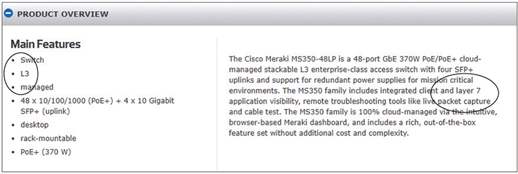
Figure 1-1 Using OSI terminology in device documentation
This chapter looks first at models in general and how models help conceptualize and troubleshoot networks. The chapter then explores the OSI seven-layer model to see how it helps clarify network architecture for techs.
Historical/Conceptual
Working with Models
Networking is hard. It takes a lot of pieces, both hardware and software, all working incredibly quickly and in perfect harmony, to get anything done. Just making Google appear in your Web browser requires millions of hours in research, development, and manufacturing to create the many pieces to successfully connect your system to a server somewhere in Googleland and to enable them to communicate. Whenever we encounter highly complex technologies, we need to simplify the overall process by breaking it into discrete, simple, individual processes. We do this using a network model.
Biography of a Model
What does the word “model” mean to you? Does the word make you think of a person walking down a catwalk at a fashion show in some outrageous costume or another showing off the latest style of blue jeans on a huge billboard? Maybe it makes you think of a plastic model airplane? What about those computer models that try to predict weather? We use the term “model” in a number of ways, but each use shares certain common themes.
All models are a simplified representation of the real thing. The human model ignores the many different types of body shapes, using only a single “optimal” figure. The model airplane lacks functional engines or the internal framework, and the computerized weather model might disregard subtle differences in wind temperatures or geology (Figure 1-2).
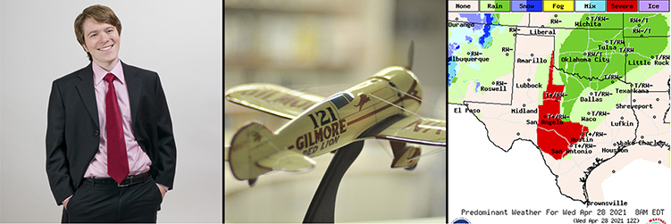
Figure 1-2 Types of models
Additionally, a model must have at least all the major functions of the real item, but what constitutes a major rather than a minor function is open to opinion. Figure 1-3 shows a different level of detail for a model. Does it contain all the major components of an airplane? There’s room for argument that perhaps the model should have landing gear to go along with the propeller, wings, and tail.
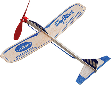
Figure 1-3 Simple model airplane
Network Models
Network models face similar challenges. What functions define all networks? What details can you omit without rendering the model inaccurate? Does the model retain its usefulness when describing a network that does not employ all the layers?
In the early days of networking, different manufacturers made unique types of networks that functioned well. Part of the reason the networks worked was that every network manufacturer made everything. Back then, a single manufacturer provided everything for a customer when the customer purchased a network solution: all the hardware and all the software in one complete and expensive package. Although these networks worked fine as stand-alone networks, the proprietary nature of the hardware and software made it difficult—to put it mildly—to connect networks of multiple manufacturers. To interconnect networks and therefore improve the networking industry, someone needed to create a guide, a model, that described the functions of a network. Using this model, the people who made hardware and software could work together to make networks that worked together well.

NOTE The International Organization for Standardization (ISO) created the OSI seven-layer model. ISO may look like a misspelled acronym, but it’s actually a word, derived from the Greek word isos, which means “equal.” The International Organization for Standardization sets standards that promote equality among network designers and manufacturers, thus ISO.
The best way to learn the OSI model is to see it in action. For this reason, I’ll introduce you to a small, simplified network that needs to copy a file from one computer to another. This example goes through each of the OSI layers needed to copy that file, and I explain each step and why it is necessary. The next part of the chapter explores a Web-centric enterprise version of a company so you can see how the OSI model applies to the latest networks. By the end of the chapter, you should have a definite handle on using the OSI model as a tool to conceptualize networks. You’ll continue to build on this knowledge throughout the book and turn your OSI model knowledge into a powerful troubleshooting tool.
The OSI Seven-Layer Model on a Simple Network
Each layer in the OSI seven-layer model defines an important function in computer networking, and the protocols that operate at that layer offer solutions to those functions. Protocols are sets of clearly defined rules, regulations, standards, and procedures that enable hardware and software developers to make devices and applications that function properly at a particular layer. The OSI seven-layer model encourages modular design in networking, meaning that each layer has as little to do with the operation of other layers as possible. Think of it as an automobile assembly line. The guy painting the car doesn’t care about the gal putting doors on the car—he expects the assembly line process to make sure the cars he paints have doors. Each layer on the model trusts that the other layers on the model do their jobs.
The OSI seven layers are
• Layer 7 Application
• Layer 6 Presentation
• Layer 5 Session
• Layer 4 Transport
• Layer 3 Network
• Layer 2 Data Link
• Layer 1 Physical
The OSI seven layers are not laws of physics—anybody who wants to design a network can do it any way he or she wants. Although many protocols fit neatly into one of the seven layers, others do not.

EXAM TIP Be sure to memorize both the name and the number of each OSI layer. Network techs use OSI terms such as “Layer 4” and “Transport layer” synonymously. Students have long used mnemonics for memorizing such lists. One of my favorites for the OSI seven-layer model is “Please Do Not Throw Sausage Pizza Away.” Yum! Another great mnemonic that helps students to memorize the layers from the top down is “All People Seem To Need Data Processing.” Go with what works for you.
Now that you know the names of the layers, let’s see what each layer does. The best way to understand the OSI layers is to see them in action. Let’s see them at work at the fictional company of MHTechEd, Inc.
NOTE This section is a conceptual overview of the hardware and software functions of a network. Your network may have different hardware or software, but it will share the same functions.
Welcome to MHTechEd!
Mike’s High-Tech Educational Supply Store and Post Office, or MHTechEd for short, has a small network of PCs running Windows, a situation typical of many small businesses today. Windows comes with all the network software it needs to connect to a network. All the computers in the MHTechEd network are connected by special network cabling.
As in most offices, everyone at MHTechEd has his or her own PC. Figure 1-4 shows two workers, Shannon and Scott, who handle all the administrative functions at MHTechEd. Because of the kinds of work they do, these two often need to exchange data between their two PCs. At the moment, Shannon has just completed a new employee handbook in Microsoft Word, and she wants Scott to check it for accuracy. Shannon could transfer a copy of the file to Scott’s computer by the tried-and-true Sneakernet method—saving the file on a flash drive and walking it over to him—but thanks to the wonders of computer networking, she doesn’t even have to get up from her chair. Let’s watch in detail each piece of the process that gives Scott direct access to Shannon’s computer, so he can copy the Word document from Shannon’s system to her own.
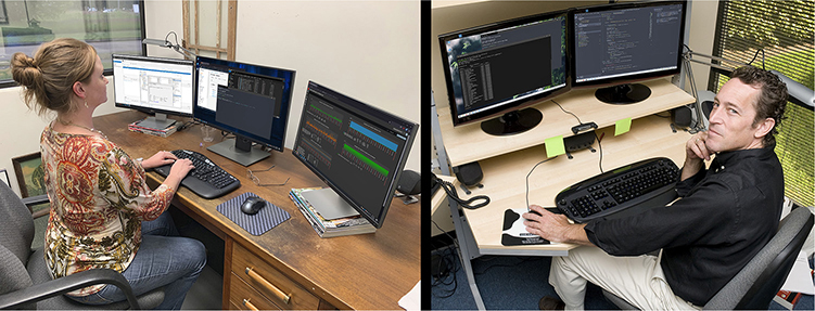
Figure 1-4 Shannon and Scott, hard at work
Long before Shannon ever saved the Word document on her system—when the systems were first installed—someone who knew what they were doing set up and configured all the systems at MHTechEd to be part of a common network. All this setup activity resulted in multiple layers of hardware and software that can work together behind the scenes to get that Word document from Shannon’s system to Scott’s. Let’s examine the different pieces of the network.
Test Specific
Let’s Get Physical—Network Hardware and Layers 1–2
Clearly the network needs a physical channel through which it can move bits of data between systems. Most networks use a cable like the one shown in Figure 1-5. This cable, known in the networking industry as unshielded twisted pair (UTP), usually contains four pairs of wires that can transmit and receive data.
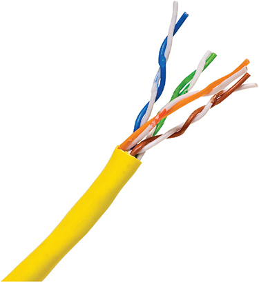
Figure 1-5 UTP cabling
Another key piece of hardware the network uses is a special box-like device that handles the flow of data from each computer to every other computer (Figure 1-6). This box is often tucked away in a closet or an equipment room. (The technology of the central box has changed over time. For now, let’s just call it the “central box.” I’ll get to variations in a bit.) Each system on the network has its own cable that runs to the central box.
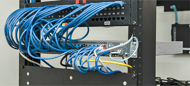
Figure 1-6 Typical central box
Layer 1 of the OSI model defines the method of moving data between computers, so the cabling and central box are part of the Physical layer (Layer 1). Anything that moves data from one system to another, such as copper cabling, fiber optics, even radio waves, is part of the OSI Physical layer. Layer 1 doesn’t care what data goes through; it just moves the data from one system to another system. Figure 1-7 shows the MHTechEd network in the OSI seven-layer model thus far. Note that each system has the full range of layers, so data from Shannon’s computer can flow to Scott’s computer. (I’ll cover what a “hub” is shortly.)
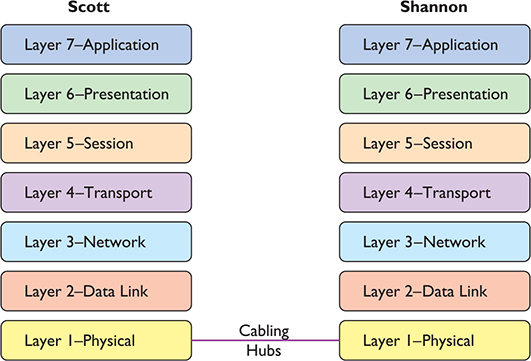
Figure 1-7 The network so far, with the Physical layer hardware installed
The real magic of a network starts with the network interface card, or NIC (pronounced “nick”), which serves as the interface between the PC and the network. While NICs come in a wide array of shapes and sizes, the ones at MHTechEd look like Figure 1-8.
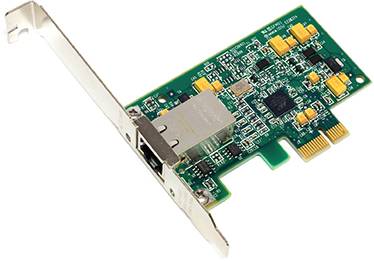
Figure 1-8 Typical NIC
On older systems, a NIC truly was a separate card that snapped into a handy expansion slot, which is why they were called network interface cards. Even though they’re now built into the motherboard, they are still called NICs.
Figure 1-9 shows a typical modern laptop with a dongle providing an Ethernet port. Note the cable runs from the NIC into the wall; inside that wall is another cable running all the way back to the central box.
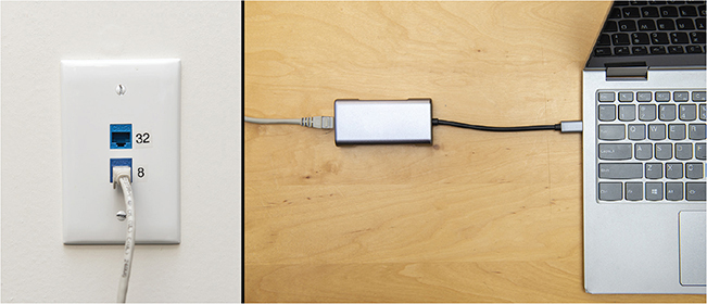
Figure 1-9 Dongle NIC with cable connecting the laptop to the wall jack
Cabling and central boxes define the Physical layer of the network, and NICs provide the interface to the PC. Figure 1-10 shows a diagram of the network cabling system. I’ll build on this diagram as I delve deeper into the network process.
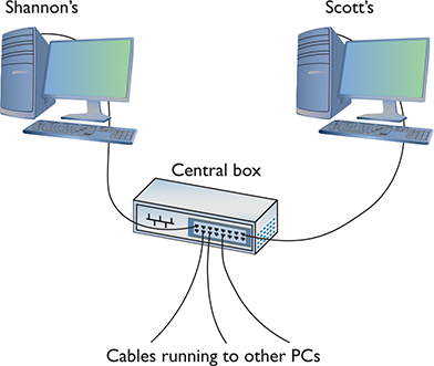
Figure 1-10 The MHTechEd network
You might be tempted to categorize the NIC as part of the Physical layer at this point, and you’d have a valid argument. The NIC clearly is necessary for the physical connection to take place. Many authors put the NIC in OSI Layer 2, the Data Link layer, though, so clearly something else is happening inside the NIC. Let’s take a closer look.
The NIC
To understand networks, you must understand how NICs work. The network must provide a mechanism that gives each system a unique identifier—like a telephone number—so data is delivered to the right system. That’s one of the NIC’s most important jobs. Inside every NIC, burned onto some type of ROM chip, is special firmware containing a unique identifier with a 48-bit value called the media access control address, or MAC address.
No two NICs ever share the same MAC address—ever. Any company that makes NICs must contact the Institute of Electrical and Electronics Engineers (IEEE) and request a block of MAC addresses, which the company then burns into the ROMs on its NICs. Many NIC makers also print the MAC address on the surface of each NIC, as shown in Figure 1-11. Note that the NIC shown here displays the MAC address in hexadecimal notation. Count the number of hex characters—because each hex character represents 4 bits, it takes 12 hex characters to represent 48 bits. MAC addresses are always written in hex.
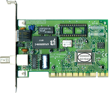
Figure 1-11 MAC address
Hexadecimal Aside
A hexadecimal numbering system uses base 16 to represent numbers—that would be 0–15 (in base 10 values). Contrast this with the more common decimal numbering system, numbered 0–9. Just as with decimal, people who work with hexadecimal need a single character to represent each number for the 16 values. Using 0–9 makes sense, but then hex is represented in letter form for the values 10–15 (A, B, C, D, E, F).
Hexadecimal works great with binary. Four bits provide the values of 0–15. 0001, for example, is the value 1; 1000 in binary is 8; 1111 is 15. When we work with MAC addresses, it’s far easier to break each 4-bit section of the 48-bit address and translate that into hex. Humans work better that way!
Back to MAC Addresses
The MAC address in Figure 1-11 is 004005-607D49, although in print, we represent the MAC address as 00–40–05–60–7D–49. The first six digits, in this example 00–40–05, represent the number of the NIC manufacturer. Once the IEEE issues those six hex digits to a manufacturer—referred to as the Organizationally Unique Identifier (OUI)—no other manufacturer may use them. The last six digits, in this example 60–7D–49, are the manufacturer’s unique serial number for that NIC; this portion of the MAC is often referred to as the device ID.
NOTE Windows uses the dash as a delimiter for the MAC address. Linux and macOS use a colon.
Would you like to see the MAC address for your NIC? If you have a Windows system, type ipconfig /all from a command prompt to display the MAC address (Figure 1-12). Note that ipconfig calls the MAC address the physical address, which is an important distinction, as you’ll see a bit later in the chapter. For macOS, type ifconfig from a terminal; for Linux, type ip a from a terminal to get similar results. Figure 1-13 shows a Kali Linux terminal; the link/ether line shows the MAC address.
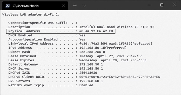
Figure 1-12 Output from ipconfig /all
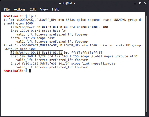
Figure 1-13 Output from ip a in Kali Linux
MAC-48 and EUI-48
The IEEE forms MAC addresses from a numbering name space originally called MAC-48, which simply means that the MAC address is 48 bits, with the first 24 bits defining the OUI, just as described here. The current term for this numbering name space is EUI-48. EUI stands for Extended Unique Identifier. (IEEE apparently went with the latter term because they could trademark it.)
Most techs just call them MAC addresses, as you should, but you might see MAC-48 or EUI-48 on the CompTIA Network+ exam.
Okay, so every NIC in the world has a unique MAC address, but how is it used? Ah, that’s where the fun begins! Recall that computer data is binary, which means it’s made up of streams of ones and zeroes. NICs send and receive this binary data as pulses of electricity, light, or radio waves. Let’s consider the NICs that use electricity to send and receive data. The specific process by which a NIC uses electricity to send and receive data is exceedingly complicated but, luckily for you, not necessary to understand. Instead, just think of a charge on the wire as a one and no charge as a zero. A chunk of data moving in pulses across a wire might look something like Figure 1-14.
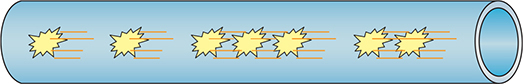
Figure 1-14 Data moving along a wire
Try This!
If you put an oscilloscope on the wire to measure voltage, you’d see something like Figure 1-15. An oscilloscope is a powerful tool that enables you to see electrical pulses.
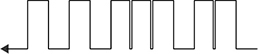
Figure 1-15 Oscilloscope of data
Now, remembering that the pulses represent binary data, visualize instead a string of ones and zeroes moving across the wire (Figure 1-16).
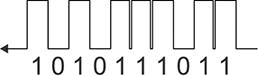
Figure 1-16 Data as ones and zeroes
Once you understand how data moves along the wire, the next question is, how does the network get the right data to the right system? All networks transmit data by breaking whatever is moving across the Physical layer (such as files, print jobs, Web pages, and so forth) into discrete chunks called frames. A frame is basically a container for a chunk of data moving across a network. A frame encapsulates—puts a wrapper around—information and data for easier transmission. (More on this later in the chapter.) The NIC creates and sends, as well as receives and reads, these frames.
NOTE The unit of data specified by a protocol at each layer of the OSI seven-layer model is called a protocol data unit (PDU). A frame is the PDU for Layer 2.
I like to visualize an imaginary table inside every NIC that acts as a frame creation and reading station. I see frames as those pneumatic canisters you see when you go to a drive-in teller at a bank. A little guy inside the network card—named Nick, of course—builds these pneumatic canisters (the frames) on the table and then shoots them out on the wire to the central box (Figure 1-17).
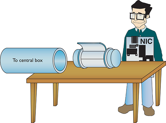
Figure 1-17 Inside the NIC
NOTE Different frame types are used in different networks. All NICs on the same network must use the same frame type, or they will not be able to communicate with other NICs.
Here’s where the MAC address becomes important. Figure 1-18 shows a representation of a generic frame, a simplified version of the wired network technology for home/office use, called Ethernet. (Chapter 3 covers Ethernet in great detail. For now just go with the frame described here as a generic wired thing.)
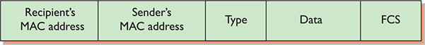
Figure 1-18 Generic frame
Even though a frame is a string of ones and zeroes, we often draw frames as a series of rectangles, each rectangle representing a part of the string of ones and zeroes. You will see this type of frame representation used quite often, so you should become comfortable with it (even though I still prefer to see frames as pneumatic canisters).
Note that the frame begins with the MAC address of the NIC to which the data is to be sent, followed by the MAC address of the sending NIC. Next comes the Type field, which indicates what’s encapsulated in the frame. Then comes the Data field that contains what’s encapsulated, followed by a special piece of checking information called the frame check sequence (FCS). The FCS uses a type of binary math called a cyclic redundancy check (CRC) that the receiving NIC uses to verify that the data arrived intact.
You can think of a frame in a different way as having three sections. The header (MAC addresses and Type) starts, followed by the payload (whatever is encapsulated in the frame); this is followed by the trailer (the FCS).
So, what’s inside the data part of the frame? The NIC neither knows nor cares. The data may be a part of a file, a piece of a print job, or part of a Web page. NICs aren’t concerned with content! The NIC simply takes whatever data is passed to it via its device driver and addresses it for the correct system. Special software will take care of what data gets sent and what happens to that data when it arrives. This is the beauty of imagining frames as little pneumatic canisters (Figure 1-19). A canister can carry anything from dirt to diamonds—the NIC doesn’t care one bit (pardon the pun).
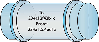
Figure 1-19 Frame as a canister
Like a canister, a frame can hold only a certain amount of data. Different types of networks use different sizes of frames, but the frames used in Ethernet networks hold at most 1500 bytes of data. This raises a new question: what happens when the data to be sent is larger than the frame size? Well, the sending system’s software must chop the data up into nice, frame-sized chunks, which it then hands to the NIC for sending. As the receiving system begins to accept the incoming frames, the receiving system’s software recombines the data chunks as they come in from the network. I’ll show how this disassembling and reassembling is done in a moment—first, let’s see how the frames get to the right system!
Into the Central Box
When a system sends a frame out on the network, the frame goes into the central box. What happens next depends on the technology of the central box.
In the early days of networking, the central box was called a hub. A hub was a dumb device, essentially just a repeater. When it received a frame, the hub made an exact copy of that frame, sending a copy of the original frame out of all connected ports except the port on which the message originated.
The interesting part of this process was when the copy of the frame came into all the other systems. I like to visualize that a frame slid onto the receiving NIC’s “frame assembly table,” where the electronics of the NIC inspected it. (This doesn’t exist; use your imagination!) Here’s where the magic took place: only the NIC to which the frame was addressed would process that frame—the other NICs simply dropped it when they saw that it was not addressed to their MAC address. This is important to appreciate: with a hub, every frame sent on a network was received by every NIC, but only the NIC with the matching MAC address would process that frame (Figure 1-20).
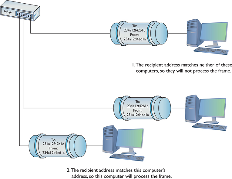
Figure 1-20 Incoming frame!
Later networks replaced the hub with a smarter device called a switch. Switches, as you’ll see in much more detail as we go deeper into networking, filter traffic by MAC address. Rather than sending all incoming frames to all network devices connected to it, a switch sends the frame only to the interface associated with the destination MAC address.
FCS in Depth
All FCSs are only 4 bytes long, yet the wired frame carries at most 1500 bytes of data. How can 4 bytes tell you if all 1500 bytes in the data are correct? That’s the magic of the math of the CRC. Without going into the grinding details, think of the CRC as just the remainder of a division problem. (Remember learning remainders from division back in elementary school?) The NIC sending the frame does a little math to make the CRC. The receiving NIC applies the same math. If the receiving NIC’s answer is the same as the CRC, it knows the data is good; if it’s not good, the frame is dropped.
Getting the Data on the Line
The process of getting data onto the wire and then picking that data off the wire is amazingly complicated. For instance, what would happen to keep two NICs from speaking at the same time? Because all the data sent by one NIC is read by every other NIC on the network, only one system could speak at a time in early wired networks. Networks use frames to restrict the amount of data a NIC can send at once, giving all NICs a chance to send data over the network in a reasonable span of time. Dealing with this and many other issues requires sophisticated electronics, but the NICs handle these issues completely on their own without our help. Thankfully, the folks who design NICs worry about all these details, so we don’t have to!
Getting to Know You
Using the MAC address is a great way to move data around, but this process raises an important question. How does a sending NIC know the MAC address of the NIC to which it’s sending the data? In most cases, the sending system already knows the destination MAC address because the NICs had probably communicated earlier, and each system stores that data. If it doesn’t already know the MAC address, a NIC may send a broadcast onto the network to ask for it. The MAC address of FF-FF-FF-FF-FF-FF is the Layer 2 broadcast address—if a NIC sends a frame using the broadcast address, every single NIC on the network will process that frame. That broadcast frame’s data will contain a request for a system’s MAC address. Without knowing the MAC address to begin with, the requesting computer will use an IP address to pick the target computer out of the crowd. The system with the MAC address your system is seeking will read the request in the broadcast frame and respond with its MAC address. (See “IP—Playing on Layer 3, the Network Layer” later in this chapter for more on IP addresses and packets.)
The Complete Frame Movement
Now that you’ve seen all the pieces used to send and receive frames, let’s put these pieces together and see how a frame gets from one system to another. The basic send/receive process is as follows.
First, the sending system’s operating system hands some data to its NIC. The NIC builds a frame to transport that data to the receiving NIC (Figure 1-21).
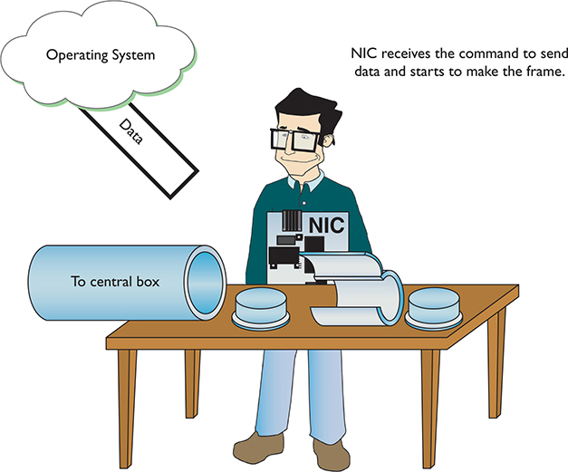
Figure 1-21 Building the frame
After the NIC creates the frame, it adds the FCS, and then dumps it and the data into the frame (Figure 1-22).
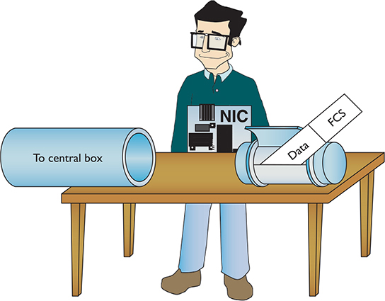
Figure 1-22 Adding the data and FCS to the frame
Next, the NIC puts both the destination MAC address and its own MAC address onto the frame. It then sends the frame through the cable to the network (Figure 1-23).
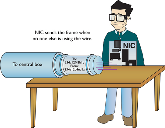
Figure 1-23 Sending the frame
NOTE Any frame addressed specifically to another device’s MAC address is called a unicast frame. The one-to-one addressing scheme is called unicast addressing; you’ll see it in other layers as well as Layer 2.
The frame propagates down the wire into the central box. The switch sends unicast frames to the destination address and sends broadcast frames to every system on the network. The NIC receives the frame (Figure 1-24). The NIC strips off all the framing information and sends the data to the software—the operating system—for processing. The receiving NIC doesn’t care what the software does with the data; its job stops the moment it passes on the data to the software.
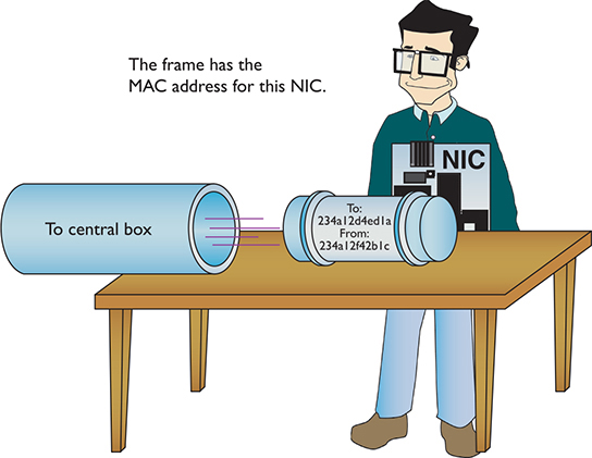
Figure 1-24 Reading an incoming frame
Any device that deals with a MAC address is part of the OSI Data Link layer, or Layer 2 of the OSI model. Let’s update the OSI model to include details about the Data Link layer (Figure 1-25).
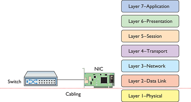
Figure 1-25 Layer 1 and Layer 2 are now properly applied to the network.
Note that the cabling (and hubs) are in the Physical layer. Switches handle traffic using MAC addresses, so they operate at Layer 2. That’s the way modern wired networks work. The NIC is in the Data Link layer and the Physical layer.
The Two Aspects of NICs
Consider how data moves in and out of a NIC. On one end, frames move into and out of the NIC’s network cable connection. On the other end, data moves back and forth between the NIC and the network operating system software. The many steps a NIC performs to keep this data moving—sending and receiving frames over the wire, creating outgoing frames, reading incoming frames, and attaching MAC addresses—are classically broken down into two distinct jobs.
NOTE Sending NICs break frames down into ones and zeroes for transmission; receiving NICS rebuild the frame on receipt. You get the idea.
The first job is called the Logical Link Control (LLC). The LLC is the aspect of the NIC that talks to the system’s operating system (usually via device drivers). The LLC handles multiple network protocols and provides flow control.
EXAM TIP The CompTIA Network+ exam tests you on the details of the OSI seven-layer model, so remember that the Data Link layer is the only layer that has sublayers.
The second job is called the Media Access Control (MAC), which creates and addresses the frame. It adds the NIC’s own MAC address and attaches MAC addresses to the frames. Recall that each frame the NIC creates must include both the sender’s and recipient’s MAC addresses. The MAC sublayer adds or checks the FCS. The MAC also ensures that the frames, now complete with their MAC addresses, are then sent along the network cabling. Figure 1-26 shows the Data Link layer in detail.
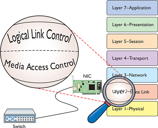
Figure 1-26 LLC and MAC, the two parts of the Data Link layer
NIC and Layers
Most networking materials that describe the OSI seven-layer model put NICs squarely into the Data Link layer of the model. It’s at the MAC sublayer, after all, that data gets encapsulated into a frame, destination and source MAC addresses get added to that frame, and error checking occurs. What bothers most students with placing NICs solely in the Data Link layer is the obvious other duty of the NIC—putting the ones and zeroes on the network cable for wired networks and in the air for wireless networks. How much more physical can you get?
Many teachers will finesse this issue by defining the Physical layer in its logical sense—that it defines the rules for the ones and zeroes—and then ignore the fact that the data sent on the cable has to come from something. The first question when you hear a statement like that—at least to me—is, “What component does the sending?” It’s the NIC, of course, the only device capable of sending and receiving the physical signal.
NICs, therefore, operate at both Layer 2 and Layer 1 of the OSI seven-layer model.
Beyond the Single Wire—Network Software and Layers 3–7
Getting data from one system to another in a simple network (defined as one in which all the computers connect to one switch) takes relatively little effort on the part of the NICs. But one problem with simple networks is that computers need to broadcast to get MAC addresses. It works for small networks, but what happens when the network gets big, like the size of the entire Internet? Can you imagine millions of computers all broadcasting? No data could get through.
Equally important, data flows over the Internet using many technologies, not just Ethernet. These technologies don’t know what to do with Ethernet MAC addresses. When networks get large, you can’t use the MAC addresses anymore.
Large networks need a logical addressing method, like a postal code or telephone numbering scheme, that ignores the hardware and enables you to break up the entire large network into smaller networks called subnets. Figure 1-27 shows two ways to set up a network. On the left, all the computers connect to a single switch. On the right, however, the LAN is separated into two five-computer subnets.
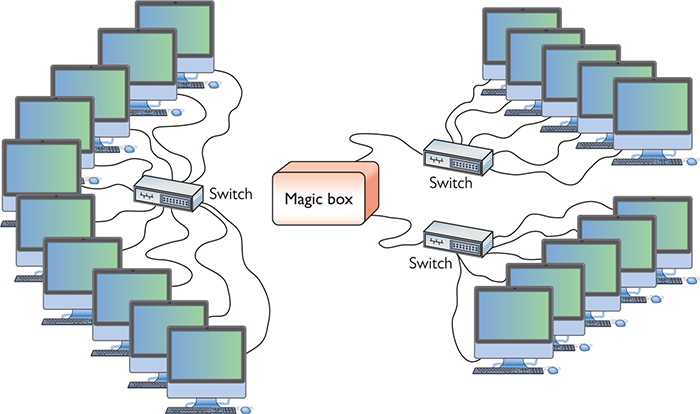
Figure 1-27 Large LAN complete (left) and broken up into two subnets (right)
To move past the physical MAC addresses and start using logical addressing requires some special software called a network protocol. Network protocols exist in every operating system. A network protocol not only has to create unique identifiers for each system, but also must create a set of communication rules for issues like how to handle data chopped up into multiple packets and how to ensure those packets get from one subnet to another. Let’s take a moment to learn a bit about the most famous collection of network protocols—TCP/IP—and its unique universal addressing system.
EXAM TIP MAC addresses are also known as physical addresses.
To be accurate, TCP/IP is really several network protocols designed to work together—better known as a protocol suite—but two protocols, TCP and IP, do so much work that the folks who invented all these protocols named the whole thing TCP/IP. TCP stands for Transmission Control Protocol, and IP stands for Internet Protocol. IP is the network protocol I need to discuss first; rest assured, however, I’ll cover TCP in plenty of detail later.
IP—Playing on Layer 3, the Network Layer
At the Network layer, Layer 3, containers called packets get created and addressed so they can go from one network to another. The Internet Protocol is the primary logical addressing protocol for TCP/IP. IP makes sure that a piece of data gets to where it needs to go on the network. It does this by giving each device on the network a unique numeric identifier called an IP address. An IP address is known as a logical address to distinguish it from the physical address, the MAC address of the NIC.
NOTE A packet is the PDU for Layer 3.
IP uses a rather unique dotted decimal notation based on four 8-bit numbers. Each 8-bit number ranges from 0 to 255, and the four numbers are separated by three periods. (If you don’t see how 8-bit numbers can range from 0 to 255, don’t worry—by the end of this book, you’ll understand these numbering conventions in more detail than you ever believed possible!) A typical IP address might look like this:
192.168.4.232
NOTE TCP/IP dominates networking today, and although it might be fun to imagine that it had humble beginnings in someone’s garage lab, that’s not the case.
In the early 1970s, two researchers at the U.S. Defense Advanced Research Projects Agency (DARPA), Robert E. Kahn and Vinton Cerf, worked out the basic parameters of what would become TCP/IP. TCP/IP offered amazing robustness in its design and eventual implementation. Government research at its most profound and world shaping!
No two systems on the same network share the same IP address; if two machines accidentally receive the same address, unintended side effects may occur. These IP addresses don’t just magically appear—they must be configured by the network administrator.
What makes logical addressing powerful is another magic box—called a router—that connects each of the subnets, as previously shown in Figure 1-27. Routers use the IP address, not the MAC address, to forward data. This enables networks to connect across data lines that don’t use Ethernet, like the telephone network. Each network type (such as Ethernet, SONET, and others that we’ll discuss later in the book) uses a unique frame. Figure 1-28 shows a typical router.
Figure 1-28 Typical small router
In a TCP/IP network, each system has two unique identifiers: the MAC address and the IP address. The MAC address (the physical address) is literally burned into the chips on the NIC, whereas the IP address (the logical address) is simply stored in the system’s software. MAC addresses come with the NIC, so you don’t configure MAC addresses, whereas you must configure IP addresses using software. Figure 1-29 shows the MHTechEd network diagram again, this time with the MAC and IP addresses displayed for each system.
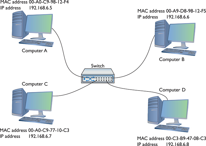
Figure 1-29 MHTechEd addressing
NOTE Try to avoid using redundant expressions. Even though many techs will say “IP protocol,” for example, you know that “IP” stands for “Internet Protocol.” It wouldn’t be right to say “Internet Protocol protocol” in English, so it doesn’t work in network speak either. (Also, don’t say “NIC card” for the same reason!)
Packets Within Frames
For a TCP/IP network to send data successfully, the data must be wrapped up in two distinct containers. A frame of some type enables the data to move from one device to another. Inside that frame are both an IP-specific container that enables routers to determine where to send data—regardless of the physical connection type—and the data itself. In TCP/IP, that inner container is the packet.
Figure 1-30 shows a typical IP packet; notice the similarity to the frames you saw earlier.
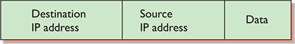
Figure 1-30 IP packet
NOTE This is a highly simplified IP packet. I am not including lots of little parts of the IP packet in this diagram because they are not important to what you need to understand right now—but don’t worry, you’ll see them later in the book!
But IP packets don’t leave their PC home without any clothes on! Each IP packet is handed to the NIC, which then encloses the IP packet in a regular frame, creating, in essence, a packet within a frame. I like to visualize the packet as an envelope, with the envelope in the pneumatic canister frame, as depicted in Figure 1-31. A more conventional drawing would look like Figure 1-32.
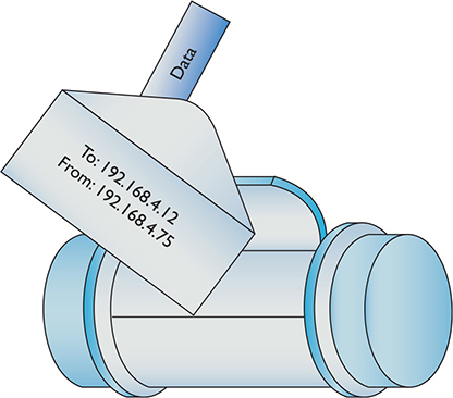
Figure 1-31 IP packet in a frame (as a canister)
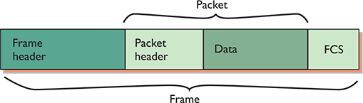
Figure 1-32 IP packet in a frame
When you send data from one computer to another on a TCP/IP network such as the Internet, that data can go through many routers before it reaches its destination. Each router strips off the incoming frame, determines where to send the data according to the IP address in the packet, creates a new frame, and then sends the packet within a frame on its merry way. The new frame type will be the appropriate technology for whatever connection technology connects to the next router. That could be a cable or DSL network connection, for example (Figure 1-33). The IP packet, on the other hand, remains unchanged.
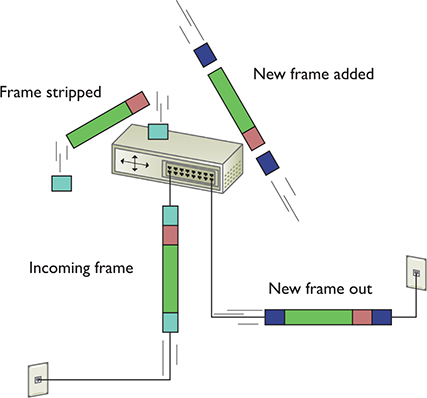
Figure 1-33 Router removing network frame and adding one for the outgoing connection
Once the packet reaches the destination subnet’s router, that router strips off the incoming frame—no matter what type—looks at the destination IP address, and then adds a frame with the appropriate destination MAC address that matches the destination IP address.
The receiving NIC strips away the Ethernet frame and passes the remaining packet off to the software. The networking software built into your operating system handles all the rest of the work. The NIC’s driver software is the interconnection between the hardware and the software. The NIC driver knows how to communicate with the NIC to send and receive frames, but it can’t do anything with the packet. Instead, the NIC driver hands the packet off to other services that know how to deal with all the separate packets and turn them into Web pages, e-mail messages, files, and so forth.
Segmentation and Reassembly—Layer 4, the Transport Layer
Because most chunks of data are much larger than a single packet, they must be chopped up before they can be sent across a network. When a serving computer receives a request for some data, it must be able to chop the requested data into chunks that will fit into a packet (and eventually into the NIC’s frame), organize the packets for the benefit of the receiving system, and hand them to the NIC for sending. This is called segmentation. The receiving system does the reassembly of the packets. It must recognize a series of incoming packets as one data transmission, reassemble the packets correctly based on information included in the packets by the sending system, and verify that all the packets for that piece of data arrived in good shape.
This part is relatively simple—the transport protocol breaks up the data into chunks called segments and gives each segment some type of sequence number. (Datagrams—also created at Layer 4—are simpler and don’t get broken up into chunks or get sequence numbers.)
I like to compare this sequencing process to the one that my favorite international shipping company uses. I receive boxes from UPS almost every day; in fact, some days I receive many, many boxes from UPS. To make sure I get all the boxes for one shipment, UPS puts a numbering system, like the one shown in Figure 1-34, on the label of each box. A computer sending data on a network does the same thing. Embedded into the data of each packet containing a segment is a sequencing number. By reading the sequencing numbers, the receiving system knows both the total number of segments and how to put them back together.
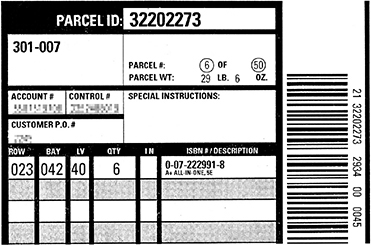
Figure 1-34 Labeling the boxes
The MHTechEd network just keeps getting more and more complex, doesn’t it? And the Word document still hasn’t been copied, has it? Don’t worry; you’re almost there—just a few more pieces to go!
Layer 4, the Transport layer of the OSI seven-layer model, has a big job: it’s the segmentation/reassembly software. As part of its job, the Transport layer also initializes requests for packets that weren’t received in good order (Figure 1-35).
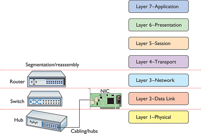
Figure 1-35 OSI updated
Connection-oriented vs. Connectionless Communication Some protocols, like the Simple Mail Transfer Protocol (SMTP) used for sending e-mail messages, require that the e-mail client and server verify that they have a connection before a message is sent (Figure 1-36). This makes sense because you don’t want your e-mail message to be a corrupted mess when it arrives.

Figure 1-36 Connection between e-mail client and server
Alternatively, a number of TCP/IP protocols simply send data without first waiting to verify that the receiving system is ready (Figure 1-37). When using Voice over IP (VoIP), for example, the call is made without verifying first whether another device is there.
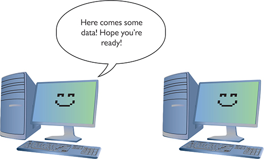
Figure 1-37 Connectionless communication
The connection-oriented protocol is Transmission Control Protocol (TCP). The connectionless protocol is User Datagram Protocol (UDP).
NOTE Chapter 6 covers TCP, UDP, and all sorts of other protocols in detail.
Everything you can do on the Internet, from Web browsing to Skype phone calls to playing World of Warcraft, is predetermined to be either connection-oriented or connectionless. It’s simply a matter of knowing your applications.
Segments Within Packets To see the Transport layer in action, strip away the IP addresses from an IP packet. What’s left is a chunk of data in yet another container called a TCP segment. TCP segments have many other fields that ensure the data gets to its destination in good order. These fields have names such as Source port, Destination port, Sequence number, and Acknowledgment number. Figure 1-38 shows a typical (although simplified) TCP segment.

Figure 1-38 TCP segment
Chapter 6 goes into more detail on TCP segments, but let’s look at source and destination ports as an example. You saw physical ports earlier in the chapter, but this use of the word “port” means something completely different. In this context, a port—a number between 1 and 65,536—is a logical value assigned to specific applications or services. A quick example will make this clear. Many TCP segments come into any computer. The computer needs some way to determine which TCP segments go to which applications. A Web server, for example, sees a lot of traffic, but it “listens” or looks for TCP segments with the destination port numbers 80 or 443, grabs those segments, and processes them. Equally, every TCP segment contains another port number—the source port—so the client knows what to do with returning information.
Data comes from the Application layer (with perhaps some input from Presentation and Session). The Transport layer breaks that data into chunks, adding port numbers and sequence numbers, creating the TCP segment. The Transport layer then hands the TCP segment to the Network layer, which, in turn, creates the IP packet.
Although a lot of traffic on a TCP/IP network uses TCP at the Transport layer, like Yoda said in The Empire Strikes Back, “There is another,” and that’s UDP. Following the same process, the Transport layer adds port and length numbers plus a checksum as a header and combines with data to create a container called a UDP datagram. A UDP datagram lacks most of the extra fields found in TCP segments, simply because UDP doesn’t care if the receiving computer gets its data. Figure 1-39 shows a UDP datagram.
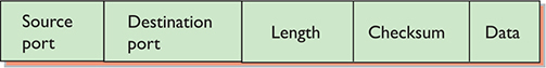
Figure 1-39 UDP datagram
Talking on a Network—Layer 5, the Session Layer
Now that you understand that the system uses software to segment and reassemble data packets, what’s next? In a network, any one system may be talking to many other systems at any given moment. For example, Shannon’s PC has a printer used by all the MHTechEd systems, so there’s a better than average chance that, as Scott tries to access the Word document, another system will be sending a print job to Shannon’s PC (Figure 1-40).

Figure 1-40 Handling multiple inputs
Shannon’s system must direct these incoming files, print jobs, Web pages, and so on, to the right programs (Figure 1-41). Additionally, the operating system must enable one system to make a connection to another system to verify that the other system can handle whatever operation the initiating system wants to perform. If Bill’s system wants to send a print job to Shannon’s printer, it first contacts Shannon’s system to ensure that it is ready to handle the print job. The session software handles this part of networking, connecting applications to applications.
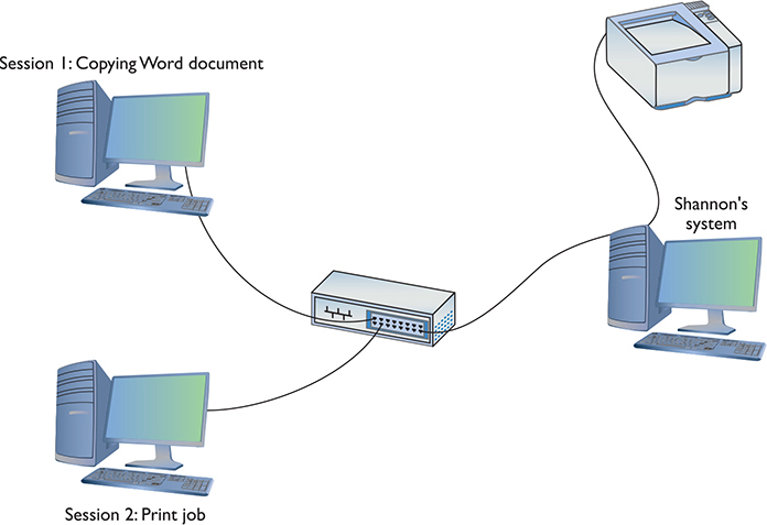
Figure 1-41 Each request becomes a session.
See Your Sessions
How many sessions does a typical system have running at one time? Well, if you have a TCP/IP network (and who doesn’t these days), you can run the netstat program from a command prompt to see all of them. Open a command prompt and type the following:
netstat –a
Then press the ENTER key to see your sessions. Don’t worry about trying to interpret what you see—Chapter 8 covers netstat in detail. For now, simply appreciate that each line in the netstat output is a session. Count them! (You can also try the ss command in Linux to view sessions.)
Layer 5, the Session layer of the OSI seven-layer model, handles all the sessions for a system (Figure 1-42). The Session layer initiates sessions, accepts incoming sessions, and opens and closes existing sessions.
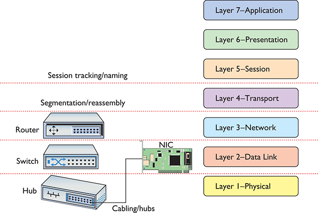
Figure 1-42 OSI updated
Many operating systems represent a session using the combination of the IP address and port numbers for both sides of a TCP or UDP communication. You can see a Web browser’s session connecting to a Web server, for example, by running netstat -n. It’ll return many lines like this:
![]()
The numbers describe the session. A Web client with IP address 192.168.4.34, using port number 45543, is in a TCP session with a Web server (we know it’s a Web server because port 80 is dedicated to Web servers) using IP address 11.12.13.123.
Translation—Layer 6, the Presentation Layer
The Presentation layer translates data from lower layers into a format usable by the Application layer, and vice versa (Figure 1-43). This manifests in several ways and isn’t necessarily clear-cut. The messiness comes into play because TCP/IP networks don’t necessarily map directly to the OSI model.
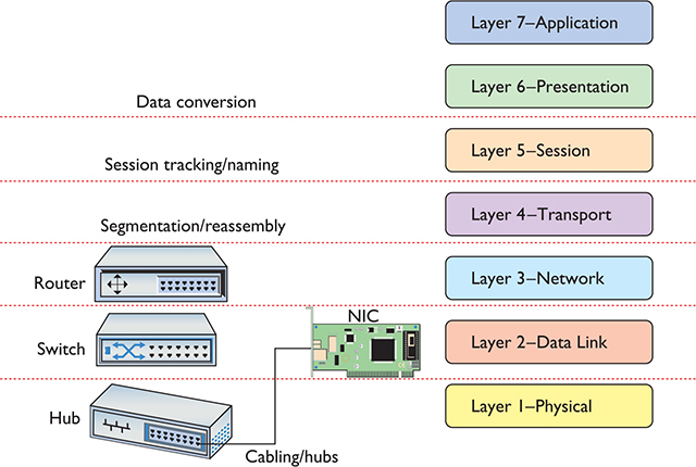
Figure 1-43 OSI updated
A number of protocols function on more than one OSI layer and can include Layer 6, Presentation. The encryption protocol used in e-commerce, Transport Layer Security (TLS), for example, seems to initiate at Layer 5 and then encrypt and decrypt at Layer 6. But even one of the authors of the protocol disputes that it should even be included in any OSI chart! It makes for some confusion.
Network Applications—Layer 7, the Application Layer
The last and most visible part of any network is the software applications that use it. If you want to copy a file residing on another system in your network, you need an applet like Network in Windows 10 that enables you to access files on remote systems. If you want to view Web pages, you need a Web browser like Google Chrome or Mozilla Firefox. The people who use a network experience it through an application. A user who knows nothing about all the other parts of a network may still know how to open an e-mail application to retrieve mail (Figure 1-44).
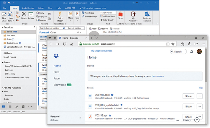
Figure 1-44 Network applications at work
Applications may include additional functions, such as encryption, user authentication, and tools to control the look of the data. But these functions are specific to the given applications. In other words, if you want to put a password on your Word document, you must use the password functions in Word to do so.
The Application layer is Layer 7 in the OSI seven-layer model. Keep in mind that the Application layer doesn’t refer to the applications themselves. It refers to the code built into all operating systems that enables network-aware applications. All operating systems have Application Programming Interfaces (APIs) that programmers can use to make their programs network aware (Figure 1-45). An API, in general, provides a standard way for programmers to enhance or extend an application’s capabilities.
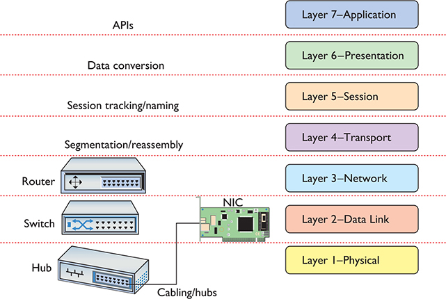
Figure 1-45 OSI updated
Encapsulation and Decapsulation
The term encapsulation encompasses the entire process of preparing data to go onto a network. This includes all the steps from the application to the Application, Presentation, Session, Transport, Network, and Data Link layers. Each layer adds more information so that the data gets to the correct recipient and the recipient knows what to do with the data.
The receiving computer reverses the process, stripping all the extra header information out as the data goes up the stack. This reverse process is called decapsulation.
The Transport layer creates a segment or datagram and hands it down to the Network layer. That layer adds IP information, encapsulating the segment or datagram. The Data Link layer wraps up all that goodness, encapsulating the packet in a frame for delivery over the network. The NIC turns the frame into bits and bytes for transmission over the network medium.
The OSI Seven-Layer Model and Remote Work
Beth works remotely for a large company as a data analyst, putting her advanced degree in information science to good use. Let’s explore her typical workflow in this section to see how the OSI seven-layer model applies.
Beth connects to the Internet wirelessly with her laptop. Her company, like so many these days, uses a number of different online services to help coordinate its far-flung workforce. These services go by names like Microsoft 365, Dropbox, GitHub, and so forth, but fundamentally these services all live on the Web and so Beth spends much of her workday in her browser of choice, Firefox (Figure 1-46).
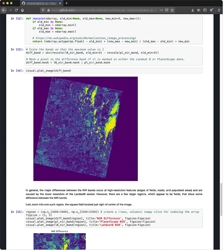
Figure 1-46 Reviewing some analysis on GitHub
In this scenario, Beth’s computer isn’t plugged into an Ethernet port. There are no local wires. Her laptop doesn’t even have an Ethernet port (because it’s modern and skinny). Do OSI layers even apply? If you answered, “Of course,” then you win a prize because they most definitely apply.
The wireless radio waves that connect Beth’s laptop to a wireless access point (WAP) operate at Layer 1 (Figure 1-47). So too do all the physical wires connecting the WAP to her router, Internet service provider (ISP), and all the routers in between there and her corporate network and other Internet-based services.
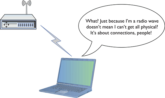
Figure 1-47 Wireless is “physical” too!
The wireless NIC in Beth’s laptop most certainly has a MAC address and connects to the WAP with frames; the WAP uses MAC addresses to connect to the local switch. That’s all clearly Layer 2 happiness.
Beth conducts almost all of her work via the Web and thus relies almost exclusively on TCP/IP for connections and interactions. By definition, her laptop must have a valid IP address or two (Layer 3) and must encapsulate/decapsulate segments and datagrams at the Transport layer (Layer 4). But the heavy lifting happens at Layer 7 with HTTP and TLS (HTTPS), because Web-based tools today rely on those protocols (as well as others). Figure 1-48 shows that the tools Beth uses all work with Layer 7.
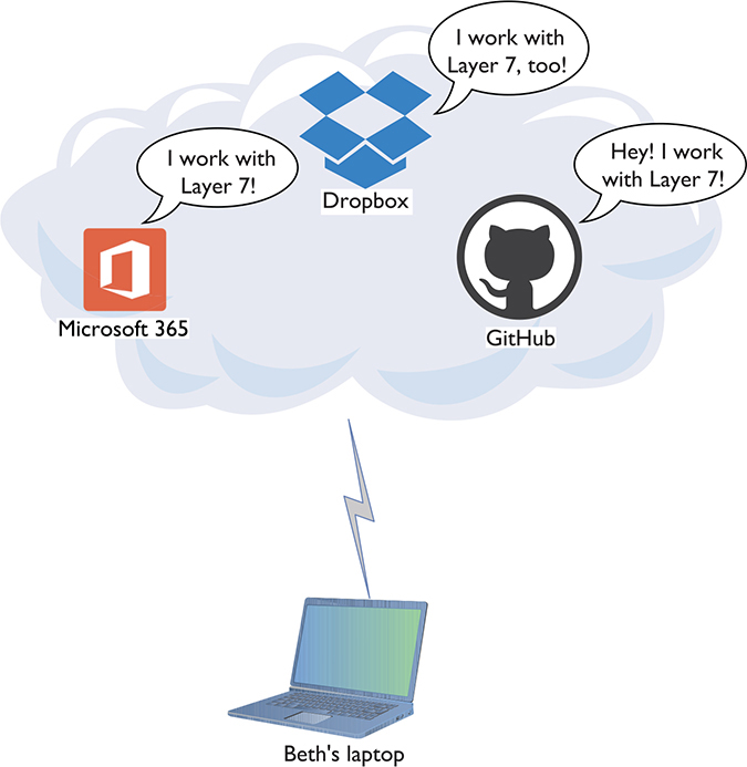
Figure 1-48 Beth’s productivity tools
The bottom line is that the OSI seven-layer model provides you with a way to conceptualize a network to determine what could cause a specific problem when the inevitable problems occur. Good techs always use a model to troubleshoot their networks. The OSI model can apply to a simple network or a more advanced network.
If Beth can’t print to a networked printer, for example, a model can help solve the problem. If her NIC shows activity, then, using the OSI model, you can set aside both the Physical layer (Layer 1) and Data Link layer (Layer 2). You’ll find yourself moving up the layer ladder to the OSI model’s Network layer (Layer 3). If her computer has a proper IP address, then you can set that layer aside too, and you can move on up to check other layers to solve the problem.
Understanding the OSI model is important. It is the primary diagnostic tool for troubleshooting networks and also the communication tool for talking with your fellow techs.
EXAM TIP Beth accesses servers to do her job; her laptop is a client of those servers. Thus, the previous scenario describes a classic client-server network type. In some circumstances, however, Beth might access resources distributed on many computers. In turn, her computer might share some of those resources with others. This alternative network type, typified by the BitTorrent file sharing protocol, is called peer-to-peer. Look for a question on the CompTIA Network+ exam that contrasts client-server and peer-to-peer networking.
Chapter Review
Questions
1. Where does (did) a hub send data?
A. Only to the receiving system
B. Only to the sending system
C. To all the systems connected to the hub
D. Only to the server
2. What uniquely identifies every NIC?
A. IP address
B. Media access control address
C. ISO number
D. Packet ID number
3. What Windows utility do you use to find the MAC address for a system?
A. ipconfig /all
B. ipcfg /all
C. ping
D. mac
4. A MAC address is known as a(n) __________ address.
A. IP
B. logical
C. physical
D. OEM
5. A NIC sends data in discrete chunks called __________.
A. segments
B. sections
C. frames
D. layers
6. The MAC address of which of the following begins a frame?
A. Receiving system
B. Sending system
C. Network
D. Router
7. A frame ends with a special bit called the frame check sequence (FCS). What does the FCS do?
A. Cycles data across the network
B. Verifies that the MAC addresses are correct
C. Verifies that the data arrived correctly
D. Verifies that the IP address is correct
8. Which of the following is an example of a MAC address?
A. 0–255
B. 00–50–56–A3–04–0C
C. SBY3M7
D. 192.168.4.13
9. Which layer of the OSI model controls the segmentation and reassembly of data?
A. Application layer
B. Presentation layer
C. Session layer
D. Transport layer
10. Which layer of the OSI model keeps track of a system’s connections to send the right response to the right computer?
A. Application layer
B. Presentation layer
C. Session layer
D. Transport layer
Answers
1. C. Data comes into a hub through one wire and is then sent out through all the other wires. A hub sends data to all the systems connected to it.
2. B. The unique identifier on a network interface card is called the media access control (MAC) address.
3. A. All versions of Windows use ipconfig /all from the command line to determine the MAC address.
4. C. The MAC address is a physical address.
5. C. Data is sent in discrete chunks called frames. Networks use frames to keep any one NIC from hogging the wire.
6. A. The frame begins with the MAC address of the receiving NIC, followed by the MAC address of the sending NIC, followed, in turn, by type of encapsulated data, the data, and FCS.
7. C. The data is followed by a special bit of checking information called the frame check sequence, which the receiving NIC uses to verify that the data arrived correctly.
8. B. A MAC address is a 48-bit value, and no two NICs ever share the same MAC address—ever. 00–50–56–A3–04–0C is a MAC address. Answer D (192.168.4.13) is an IP address.
9. D. The Transport layer controls the segmentation and reassembly of data.
10. C. The Session layer keeps track of a system’s connections to ensure that it sends the right response to the right computer.