CHAPTER 6
TCP/IP Basics
The CompTIA Network+ certification exam expects you to know how to
• 1.1 Compare and contrast the Open Systems Interconnection (OSI) model layers and encapsulation concepts
• 1.2 Explain the characteristics of network topologies and types
• 1.4 Given a scenario, configure a subnet and use appropriate IP addressing schemes
• 1.5 Explain common ports and protocols, their application, and encrypted alternatives
• 1.6 Explain the use and purpose of network services
• 2.3 Given a scenario, configure and deploy common Ethernet switching features
• 4.2 Compare and contrast common types of attacks
• 5.5 Given a scenario, troubleshoot general networking issues
To achieve these goals, you must be able to
• Describe how the TCP/IP protocol suite works
• Explain CIDR and subnetting
• Describe the functions of static and dynamic IP addresses
The mythical MHTechEd network (remember that from Chapter 1?) provided an overview of how networks work. The foundation of every physical network is hardware: wires, network interface cards, and other stand-alone network devices that move data from one computer to another. This hardware corresponds to OSI Layers 1 and 2—the Physical and Data Link layers (though some devices may also perform higher-layer functions). The higher layers of the model—from Network up to Application—work with this hardware to make network magic.
Chapters 2 through 5 provided details of the hardware at the Physical and Data Link layers of the OSI model. You learned about the network protocols, such as Ethernet, which standardize networking so that data sent by one NIC can be read correctly by another NIC.
This chapter begins a fun journey into the software side of networking. You’ll learn the details about the IP addressing scheme that enables computers on one network to communicate with each other and with computers on other networks. You’ll get the full story of how TCP/IP networks divide into smaller units—subnets—to make management of a large TCP/IP network easier. And you won’t just get it from a conceptual standpoint. This chapter provides the details you’ve undoubtedly been craving—it teaches you how to set up a network properly. The chapter finishes with an in-depth discussion on implementing IP addresses.
Historical/Conceptual
The early days of networking, roughly the 1980s, exposed a problem in the way the software developers created the programs that powered networks at the time. Unlike the hardware organizations that worked together to make solid standards, the different organizations developing network software worked separately, secretly, and competitively. The four major players—Microsoft, Apple, Novell, and UNIX developers such as AT&T—created network software solutions that were mostly incompatible and had very different answers to the question “What do we share on a network?”
Microsoft, Apple, and Novell created networking software that for the most part did nothing more than share different computers’ folders and printers (and they all did this sharing differently). AT&T and the universities developing the UNIX operating system saw networks as a way to share terminals, send e-mail messages, and transfer files. As a result, everyone’s software had its own set of Rules of What a Network Should Do and How to Do It. These sets of rules—and the software written to follow these rules—were broken down into individual rules or languages called protocols. No single protocol could do everything a network needed to do, so companies lumped together all their necessary protocols under the term protocol suite. Novell called its protocol suite IPX/SPX; Microsoft’s was called NetBIOS/NetBEUI; Apple called its protocol suite AppleTalk; and the UNIX folks used this wacky protocol suite called TCP/IP.
It took about 20 very confusing years, but eventually TCP/IP replaced every other protocol suite in all but the most rare and unique situations. To get ahead today, to get on the Internet, and to pass the CompTIA Network+ exam, you only need to worry about TCP/IP. Microsoft, Apple, and Linux developers no longer actively support anything but TCP/IP. You live in a one-protocol-suite world, the old stuff is forgotten, and you kids don’t know how good you’ve got it!
Test Specific
The TCP/IP Protocol Suite
If you recall from Chapter 1, the first two layers of the OSI seven-layer model deal with physical connectivity—wires and such—and protocols that interact with the physical. These are Layer 1, Physical, and Layer 2, Data Link. The TCP/IP protocol suite operates at Layers 3–7 of the OSI seven-layer model. This chapter explores Layer 3, Network, for the most part, though I’ll remind you about Layer 4, Transport protocols, and Layer 7, Application protocols, before the deep dive into the Network layer.
Network Layer Protocols
Internet Protocol (IP) works at the Network layer, where it takes data chunks from the Transport layer (which become the packet’s payload), adds addressing, and creates the final IP packet. IP then hands the IP packet to the Data Link layer for encapsulation into a frame.
Let’s look at the addressing in more depth. I think it’s safe to assume that most folks have seen IP addresses before. Here’s a typical example:
192.168.1.115
This type of address—four values ranging from 0 to 255, separated by three periods—is known officially as an Internet Protocol version 4 (IPv4) address.
This chapter introduces you to IPv4 addresses. You should understand the correct name for this older type of address because the world is in a slow transition to a newer, longer type of IP address called IPv6. Here’s an example of an IPv6 address:
2001:0:4137:9e76:43e:2599:3f57:fe9a
IPv4 and IPv6 aren’t the only TCP/IP protocols that work at the Network layer. Internet Control Message Protocol (ICMP), for example, plays a role in IP error reporting and diagnostics. TCP/IP users rarely start a program that uses ICMP (or its IPv6 counterpart, ICMPv6). For the most part, software automatically uses ICMP as needed without direct user action. There are exceptions to every rule: the ping utility, a popular network diagnostic tool, directly uses ICMP. You can use ping to answer a question like, “can my computer communicate with any device at the IP address 192.168.1.15?”
When thinking about the Network layer, remember the following three protocols:
• IPv4 (normally referred to as simply “IP”)
• IPv6
• ICMP
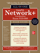
Figure 6-1 shows a highly simplified Internet Protocol (IP) header.
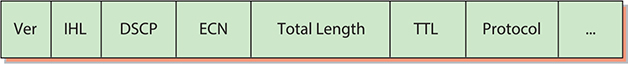
Figure 6-1 Simplified IPv4 header

NOTE Chapter 12 goes into IPv6 in detail.
The full IPv4 packet header has 14 different fields. As discussed in Chapter 1, the destination and source IP address fields are critical for getting packets to their destination. Dissecting the entire set of fields isn’t important this early in the discussion, but here are a few to whet your appetite:
• Version The version (Ver) field defines the IP address type: 4, for IPv4. If you’re thinking, “Hey, Mike, what about 6?” I’ve got a surprise for you. The IPv6 packet header also starts with a version field (which is “6”), but the formats differ after that field. We’ll look at the IPv6 header format separately in Chapter 12.
• Total Length The total size of the IP packet in octets. This includes the IP header and its payload. This field is 16 bits, which limits the packet size to 65 KB.
• Time to Live (TTL) Implementations of routers on the Internet are not perfect and engineers sometimes create loops. The TTL field prevents an IP packet from indefinitely spinning through the Internet by using a counter that decrements by one every time a packet goes through a router. This number cannot start higher than 255; many operating systems start at 128.
• Protocol In most cases, the protocol field is either TCP or UDP and identifies what’s encapsulated inside the packet. See the next section for more information.
Transport Layer Protocols
When moving data from one system to another, the TCP/IP protocol suite needs to know if the communication is connection-oriented or connectionless. If the data moving between two systems must get there in good order, a connection-oriented application is the safe bet. If it’s not a big deal for data to miss a bit or two, then connectionless is the way to go. The connection-oriented protocol used with TCP/IP is called the Transmission Control Protocol (TCP). The connectionless one is called the User Datagram Protocol (UDP).
Let me be clear: you don’t choose TCP or UDP. The people who develop an application decide which protocol to use. The people who build Discord or Twitch or Firefox or Zoom pick (and sometimes even design) one or more protocols that they think will meet their application’s needs. These protocols are, in turn, designed to use TCP, UDP, or both.
TCP
Most TCP/IP applications use TCP—that’s why the protocol suite is called “TCP/IP” and not “UDP/IP.” TCP gets an application’s data from one machine to another reliably and completely. As a result, TCP comes with communication rules that require both the sending and receiving machines to acknowledge the other’s presence and readiness to send and receive data. This process is referred to as the TCP three-way handshake of SYN, SYN-ACK, and ACK (Figure 6-2). TCP also chops up data into segments, gives the segments a sequence number, and then verifies that all sent segments were received. If a segment goes missing, the receiving system must request the missing segments.
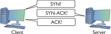
Figure 6-2 TCP three-way handshake in action
Figure 6-3 shows a simplified TCP header. Notice the source port and the destination port. Port numbers, which range from 1 to 65,535, are used by systems to determine what application needs the received data. Each application is assigned a specific port number on which to listen/send. Web servers use port 80 (HTTP) or 443 (HTTPS), for example, whereas port 143 is used to receive e-mail messages from e-mail servers (IMAP4).
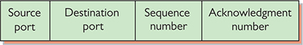
Figure 6-3 TCP header

EXAM TIP You might be required to select the fully spelled-out version of “TCP header” on the CompTIA Network+ exam, as in Transmission Control Protocol (TCP) header.
The client uses the source port number to remember which client application requested the data. The rest of this book dives much deeper into ports. For now, know that the TCP or UDP header inside an IP packet stores these values.
Ports aren’t the only items of interest in the TCP header. The header also contains these fields:
• Sequence number and acknowledgment number These numbers enable the sending and receiving computers to keep track of the various pieces of data flowing back and forth.
• Flags These individual bits give both sides detailed information about the state of the connection. (These appear in the CompTIA Network+ objectives as TCP flags.)
• Checksum The recipient can use the checksum to check the TCP header for errors such as bits flipped or lost during transmission.
UDP
UDP is the “fire and forget” missile of the TCP/IP protocol suite. As you can see in Figure 6-4, a UDP datagram header doesn’t possess any of the extra fields TCP segment headers carry to make sure the data is received intact. UDP works best when you have a lot of data that doesn’t need to be perfect or when the systems are so close to each other that the chances of a problem occurring are too small to bother worrying about. A few dropped frames on a Voice over IP call, for example, won’t make much difference in the communication between two people. So, there’s a good reason to use UDP: it’s smoking fast compared to TCP. Two of the most important networking protocols, Domain Name System (DNS) and Dynamic Host Configuration Protocol (DHCP), use UDP.
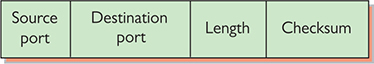
Figure 6-4 UDP header
EXAM TIP You might be required to select the fully spelled-out version of “UDP header” on the CompTIA Network+ exam, as in User Datagram Protocol (UDP) header.
NOTE You saw this back in Chapter 1, but I’ll mention it again here. Data gets chopped up into chunks at the Transport layer when using TCP. The chunks are called segments with TCP. UDP datagrams don’t get chopped up at the Transport layer; they just get a header.
Application Layer Protocols
TCP/IP applications use TCP/IP protocols to move data back and forth between clients and servers. Because every application has different needs, I can’t show you a generic application header. Instead, we’ll look at a sample header from a pillar of the World Wide Web—the Hypertext Transfer Protocol (HTTP).
Web servers and Web browsers use HTTP (or, more accurately, HTTPS, a secure version of HTTP wrapped in encryption—we’ll take a closer look at it in Chapter 10) to communicate. Figure 6-5 shows a sample header for HTTP. Specifically, this header is a response from a Web server containing a resource the client previously requested. This header—it’s just text—begins with “HTTP/1.1,” which indicates the version of the HTTP protocol in use. The “200 OK” indicates a successful request. The first blank line separates the end of the header from the beginning of the response body (which contains the requested Web page).
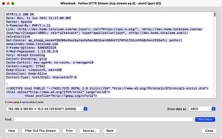
Figure 6-5 HTTP header
NOTE I’m simplifying the call and response interaction between a Web server and a Web client. The explanation here is only part of the process of accessing a Web page.
Super! Now that you’re comfortable with how the TCP/IP protocols fit into clear points on the OSI seven-layer model, let’s head back to the Network layer and explore IP addressing.
IP and Ethernet
TCP/IP supports simple networks and complex networks. You can use the protocol suite and a switch to connect a handful of computers in the same place into a local area network (LAN). TCP/IP also enables you to interconnect multiple LANs into a wide area network (WAN). Let’s start by examining how IP addressing works in a simple network, a LAN.
NOTE We say LAN so often in networking that you might assume it has a crystal-clear definition, but there’s a bit of art in it. A LAN generally (but not always) belongs to one household or organization. A LAN covers a limited place—but that can mean anything from two devices in an apartment up to thousands of devices on a multi-building school or business campus.
A WAN in a basic sense means a collection of interconnected LANs. Most authors also add a geographical context to the term, such as “spread out over a large area.”
At the LAN level, every host runs TCP/IP software over Ethernet hardware, creating a situation where every host has two addresses: an IP address and an Ethernet MAC address (Figure 6-6). While at first this seems redundant, it’s the power behind TCP/IP’s ability to support both LANs and WANs. But again, we’re only talking about LANs at this point.
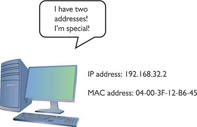
Figure 6-6 Two addresses
Imagine a situation where one computer, Computer A, wants to send an IP packet to another computer, Computer B, on the LAN. To send an IP packet to another computer, the sending computer (Computer A) must insert the IP packet into an Ethernet frame, as shown in Figure 6-7.
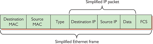
Figure 6-7 Encapsulation of an IP packet inside an Ethernet frame
Note that the IP packet is completely encapsulated inside the Ethernet frame. Also note that the Ethernet header—the initial portion of the frame—has both a destination MAC address and a source MAC address, while the IP packet encapsulated in the Ethernet frame has both a source IP address and a destination IP address. This encapsulation idea works great, but there’s a problem: Computer A knows Computer B’s IP address, but how does Computer A know the MAC address of Computer B? (See Figure 6-8.)

Figure 6-8 What is its MAC address?
NOTE The Ethernet header includes the destination and source MAC addresses, plus the Type field. The latter can indicate the size of the payload in octets or the protocol of the encapsulated payload.
To get Computer B’s MAC address, Computer A sends a special query called an ARP request to MAC address FF-FF-FF-FF-FF-FF, the universal MAC address for broadcast (Figure 6-9). The switch forwards the broadcast to every connected node.
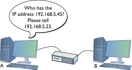
Figure 6-9 Sending an ARP request
EXAM TIP The process and protocol used in resolving an IP address to an Ethernet MAC address is called Address Resolution Protocol (ARP).
Computer B responds to the ARP request by sending Computer A an ARP reply (Figure 6-10) through the switch. Once Computer A has Computer B’s MAC address, it starts sending unicast Ethernet frames to Computer B through the switch.
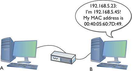
Figure 6-10 Computer B responds.
Try This!
ARP in Windows
To show a Windows system’s current ARP cache, open a command line and type
arp –a
You should see results like this:
Now delete one of the entries in the ARP table with this command:
arp –d [ip address from the previous results]
Run the arp –a command again. The line for the address you specified should be gone. Now ping the address you deleted and check the ARP table again. Did the deleted address return?
IP addresses provide several benefits that MAC addresses alone cannot offer. First, IP addresses are not a fixed part of the NIC. They can be changed to suit the needs of the network designer. Second, IP addresses group together sets of computers into logical networks, so you can, for example, distinguish one LAN from another. Finally, because TCP/IP network equipment understands the IP addressing scheme, computers can communicate with each other across all of the LANs that make up a WAN. Let’s go into more detail on IP addresses.
IP Addresses
The most common type of IP address (officially called IPv4, but usually simplified to just “IP”) consists of a 32-bit value. Here’s an example of an IP address:
11000000101010000000010000000010
Whoa! IP addresses are just strings of 32 binary digits? Yes, they are, but to make IP addresses easier for humans to use, the 32-bit binary value is broken down into four groups of eight, separated by periods, or dots, like this:
11000000.10101000.00000100.00000010
Each of these 8-bit values is, in turn, converted into a decimal number between 0 and 255. If you took every possible combination of eight binary values and placed them in a spreadsheet, it would look something like the list in the left column. The right column shows the same list with a decimal value assigned to each.
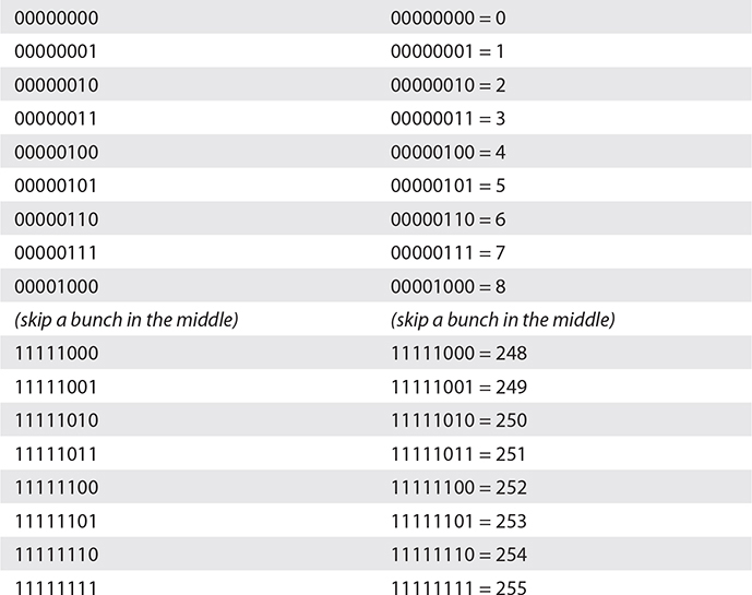
Converted, the original value of 11000000.10101000.00000100.00000010 is displayed as 192.168.4.2 in IPv4’s dotted decimal notation. Note that dotted decimal is simply a shorthand way for people to discuss and configure the binary IP addresses computers use.
People who work on TCP/IP networks must know how to convert dotted decimal to binary and back. You can convert easily using any operating system’s calculator. Every OS has a calculator (UNIX/Linux systems have about 100 different ones to choose from) that has a scientific or programmer mode like the ones shown in Figure 6-11.
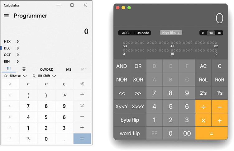
Figure 6-11 Windows (left) and macOS (right) calculators in Programmer mode
![]()
SIM Check out two excellent Chapter 6 “Binary Calculator” sims over at https://totalsem.com/008. Watch the Show! and then practice on the Click!
To convert from decimal to binary, go to decimal view, enter the decimal value, and then switch to binary view to get the result. To convert from binary to decimal, go to binary view, enter the binary value, and switch to decimal view to get the result. Figure 6-12 shows the result of Windows 10 Calculator converting the decimal value 42 into binary. Notice the result is 101010—the leading two zeroes do not appear. When you work with IP addresses, you must always have eight digits, so just add two more to the left to get 00101010.
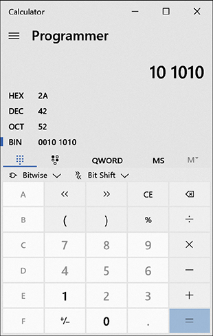
Figure 6-12 Converting decimal to binary with Windows 10 Calculator
NOTE Using a calculator utility to convert to and from binary/decimal is a critical skill for a network tech. Later on you’ll do this again, but by hand!
Just as every MAC address must be unique on a network, every IP address must be unique as well. For logical addressing to work, no two computers on the same network may have the same IP address. In a small network running TCP/IP, every computer has both an IP address and a MAC address (Figure 6-13), as you know from earlier in the chapter.

Figure 6-13 A small network with both IP and MAC addresses
Every operating system comes with utilities to display a system’s IP address and MAC address. Figure 6-14 shows a macOS system’s Network utility with TCP/IP information displayed. Note the IP address (192.168.50.157). Figure 6-15 shows the Hardware information in the same utility, which shows the MAC address.
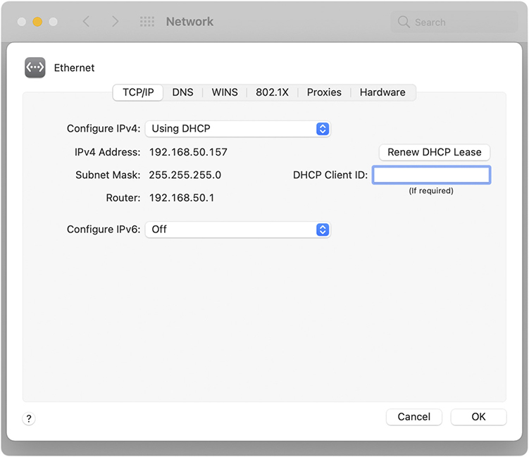
Figure 6-14 macOS Network utility
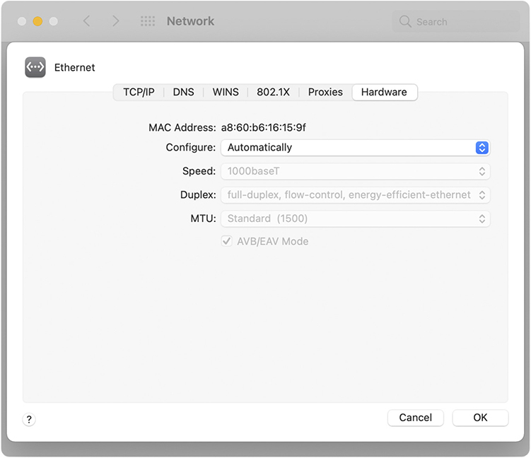
Figure 6-15 macOS Network utility displaying a MAC address
Every operating system also has a command-line utility that gives you this information. In Windows, for example, the ipconfig command can display the IP and MAC addresses. (The latter requires the /all switch.) Run ipconfig /all to see the results shown in Figure 6-16.
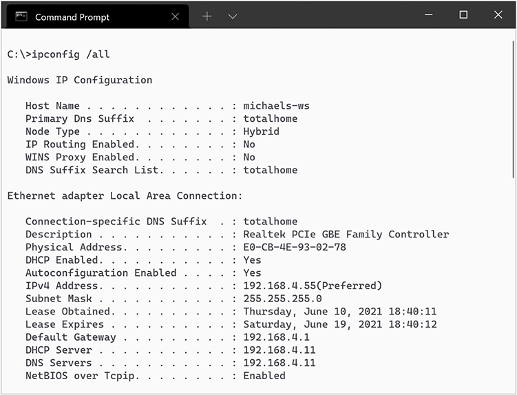
Figure 6-16 Result of running ipconfig /all in Windows
In macOS, you can run the very similar ifconfig command. Figure 6-17, for example, shows the result of running ifconfig (“en0” is the NIC) from the terminal.
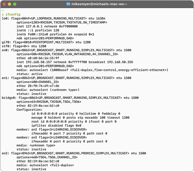
Figure 6-17 Result of running ifconfig in macOS
On Linux systems, you can run either the newer ip address (see Figure 6-18) or the older ifconfig from a terminal to display a system’s IP and MAC addresses. (A lot of distros have removed net-tools, so ifconfig won’t be an option.) Note that most distros enable you to shorten the command switch and will fill in the word “address.” So ip addr or even ip a will work.
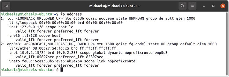
Figure 6-18 Result of running ip address in Ubuntu
EXAM TIP Make sure you know that ipconfig, ifconfig, and ip provide a tremendous amount of information regarding a system’s TCP/IP settings.
IP Addresses in Action
Now that you understand that an IP address is nothing more than a string of 32 ones and zeroes, it’s time to (finally) see how IP addressing supports WANs. It’s important to keep in mind that the IP numbering system must support both WANs and the many LANs connected by the WANs. This can create problems in some circumstances, such as when a computer needs to send data both to computers in its own network and to computers in other networks at the same time.
To make all this work, the IP numbering system must do three things:
• Create network IDs, a way to use IP addresses so that each LAN has its own identification.
• Interconnect the LANs using routers and give those routers some way to use the network ID to send packets to the right network.
• Use a subnet mask to give each computer on the network a way to recognize if a packet is for the LAN or for a computer on the WAN, so it knows how to handle the packet.
Network IDs
A WAN is nothing more than a group of two or more interconnected LANs. For a WAN to work, each LAN needs some form of unique identifier called a network ID.
To differentiate LANs from one another, each computer on a single LAN must share a very similar, but not identical, IP address. Some parts of the IP address will match all the others on the LAN. Figure 6-19 shows a LAN where all the computers share the first three numbers of the IP address, with only the last number being unique on each system.
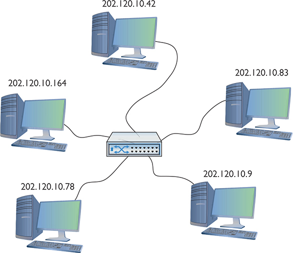
Figure 6-19 IP addresses for a LAN
In this example, every computer has an IP address of 202.120.10.x, where the x value is unique for every host, but every host’s IP address starts with 202.120.10. That means the network ID is 202.120.10.0. The x part of the IP address is the host ID. Combine the network ID (after dropping the ending 0) with the host ID to get an individual system’s IP address. No individual computer can have an IP address that ends with 0 because that is reserved for network IDs.
NOTE Two things to note here. First, the network ID and the host ID are combined to make a system’s IP address. Second, a host ID can end in 0—as long as it isn’t all zeroes—but we have to discuss subnetting before any of this will make sense. Read on!
Interconnecting LANs
To organize all those individual LANs into a larger network, every TCP/IP LAN that wants to connect to another TCP/IP LAN must have a router connection. There is no exception to this critical rule. A router, therefore, needs an IP address on every LAN that it interconnects (Figure 6-20), so it can correctly send (route) the packets to the correct LAN.
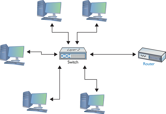
Figure 6-20 LAN with router
When you have a router that routes traffic out to other networks, both the router’s interface on a LAN and the router itself are called the default gateway. In a typical scenario configuring a client to access the network beyond the router, you use the IP address of the default gateway. The default gateway is in the same network ID as the host. The network administrator who sets up the router must make sure to configure the router’s LAN interface to have an address in the LAN’s network ID. By convention, most network administrators give the LAN-side NIC on the default gateway the lowest or highest host address in the network. Therefore, if a network ID is 22.33.4.x, the router might be configured to use the address 22.33.4.1 or 22.33.4.254.
Routers use network IDs to determine network traffic. Figure 6-21 shows a diagram for a small, two-NIC router similar to the ones you see in many homes. Note that one port (202.120.10.1) connects to the LAN and the other port connects to the Internet service provider’s network (14.23.54.223). Built into this router is a routing table: the actual instructions that tell the router what to do with incoming packets and where to send them.
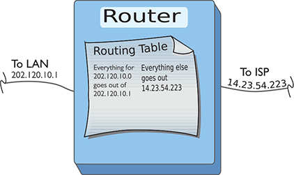
Figure 6-21 Router diagram
Now let’s add in the LAN and the Internet (Figure 6-22). When discussing networks in terms of network IDs (especially with illustrations in books) the common practice is to draw a circle around an illustrated network. Here, you should concentrate on the IDs—not the specifics of the networks.
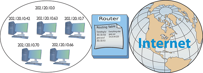
Figure 6-22 LAN, router, and the Internet
NOTE Routing tables are covered in more detail in Chapter 7.
Network IDs are very flexible, as long as no two interconnected networks share the same network ID. If you wished, you could change the network ID of the 202.120.10.0 network to 202.155.5.0, or 202.21.8.0, but only if you can guarantee that no other LAN on the WAN shares the same network ID. On the Internet, powerful governing bodies carefully allocate network IDs to ensure no two LANs share the same network ID. I’ll talk more about how this works later in the chapter.
So far, you’ve only seen examples of network IDs where the last value is zero. This is common for small networks, but it creates a limitation. With a network ID of 202.120.10.0, for example, a network is limited to IP addresses from 202.120.10.1 to 202.120.10.254. (202.120.10.255 is a broadcast address used to talk to every computer on the LAN.) This provides only 254 IP addresses: enough for a small network, but many organizations need many more IP addresses. No worries! You can simply use a network ID with more zeroes, such as 170.45.0.0 (for a total of 65,534 hosts) or even 12.0.0.0 (for around 16.7 million hosts).
Network IDs enable you to connect multiple LANs into a WAN. Routers then connect everything together, using routing tables to keep track of which packets go where. So that takes care of the second task: interconnecting the LANs using routers and giving those routers a way to send packets to the right network.
Now that you know how IP addressing works with LANs and WANs, let’s turn to how IP enables each computer on a network to recognize if a packet is going to a computer on the LAN or to a computer on the WAN. The secret to this is something called the subnet mask.
Subnet Mask
Picture this scenario. Three friends sit at their computers—Computers A, B, and C—and want to communicate with each other. Figure 6-23 illustrates the situation. You can tell from the drawing that Computers A and B are in the same LAN, whereas Computer C is on a completely different LAN. The IP addressing scheme can handle this communication, so let’s see how it works.
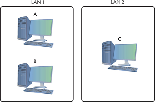
Figure 6-23 The three amigos, separated by walls or miles
The process to get a packet to a local computer is very different from the process to get a packet to a faraway computer. If one computer wants to send a packet to a local computer, it must send a broadcast to get the other computer’s MAC address. (It’s easy to forget about the MAC address, but remember that Layer 2 requires the MAC address to get the packet to the other computer.) If the packet is for some computer on a faraway network, the sending computer must send the packet to the default gateway (Figure 6-24).
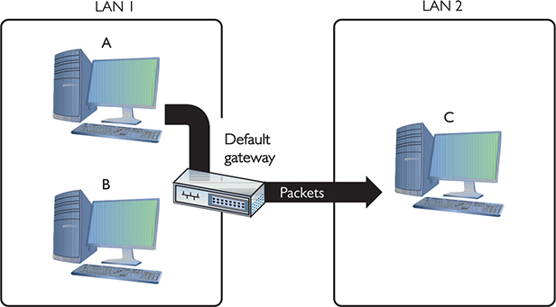
Figure 6-24 Sending a packet to a remote location
In the scenario illustrated in Figure 6-23, Computer A wants to send a packet to Computer B. Computer B is on the same LAN as Computer A, but that begs a question: How does Computer A know this? Every TCP/IP computer needs a tool to tell the sending computer whether the destination IP address is local or long distance. This tool is the subnet mask.
A subnet mask is nothing more than a string of ones followed by some number of zeroes, always totaling exactly 32 bits, set on every TCP/IP host. Here’s an example of a typical subnet mask:
11111111111111111111111100000000
For the courtesy of the humans reading this (if any computers are reading this book, please call me—I’d love to meet you!), let’s convert this to dotted decimal. First, add some dots:
11111111.11111111.11111111.00000000
Then convert each octet into decimal (use a calculator):
255.255.255.0
When you line up an IP address with a corresponding subnet mask in binary, the portion of the IP address that aligns with the ones of the subnet mask is the network ID portion of the IP address. The portion that aligns with the zeroes is the host ID. With simple IP addresses, you can see this with dotted decimal, but you’ll want to see this in binary for a true understanding of how the computers work.

TIP At this point, you should memorize that 0 = 00000000 and 255 = 11111111. You’ll find knowing this very helpful throughout the rest of the book.
The IP address 192.168.5.23 has a subnet mask of 255.255.255.0. Convert both numbers to binary and then compare the full IP address to the ones and zeroes of the subnet mask:

Before a computer sends out any data, it first compares its network ID to the destination’s network ID. If the network IDs match, then the sending computer knows the destination is local. If they do not match, the sending computer knows it’s a long-distance call.
NOTE The explanation about comparing an IP address to a subnet mask simplifies the process, leaving out how the computer uses its routing table to accomplish the goal. We’ll get to routing and routing tables in Chapter 7. For now, stick with the concept of the node using the subnet mask to determine the network ID.
Let’s head over to Computer A and see how the subnet mask works. Computer A’s IP address is 192.168.5.23. Convert that into binary:
11000000.10101000.00000101.00010111
Now drop the periods because they mean nothing to the computer:
11000000101010000000010100010111
Let’s say Computer A wants to send a packet to Computer B. Computer A’s subnet mask is 255.255.255.0. Computer B’s IP address is 192.168.5.45. Convert this address to binary:
11000000101010000000010100101101
Computer A compares its IP address to Computer B’s IP address using the subnet mask, as shown in Figure 6-25. For clarity, I’ve added a line to show you where the ones end and the zeroes begin in the subnet mask. Computers certainly don’t need the line!
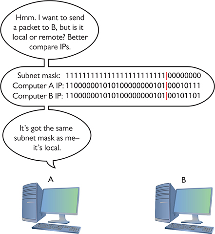
Figure 6-25 Comparing addresses
Aha! Computer A’s and Computer B’s network IDs match! It’s a local call. Knowing this, Computer A can now send out an ARP request, which is a broadcast, to determine Computer B’s MAC address. Address Resolution Protocol (ARP) is how a TCP/IP network figures out the MAC address based on the destination IP address, as you’ll recall from earlier in the chapter.

Figure 6-26 Comparing addresses again
But what happens when Computer A wants to send a packet to Computer C? First, Computer A compares Computer C’s IP address to its own using the subnet mask (Figure 6-26). It sees that the IP addresses do not match in the all-ones part of the subnet mask—meaning the network IDs don’t match; therefore, this is a long-distance call.
Whenever a computer wants to send to an IP address on another LAN, it knows to send the packet to the default gateway. It still sends out an ARP broadcast, but this time it’s to learn the MAC address for the default gateway (Figure 6-27). Once Computer A gets the default gateway’s MAC address, it then begins to send packets.
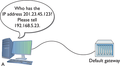
Figure 6-27 Sending an ARP request to the gateway
Subnet masks are represented in dotted decimal like IP addresses—just remember that both are really 32-bit binary numbers. All the following (shown in both binary and dotted decimal formats) can be subnet masks:
11111111111111111111111100000000 = 255.255.255.0
11111111111111110000000000000000 = 255.255.0.0
11111111000000000000000000000000 = 255.0.0.0
Most network folks represent subnet masks using shorthand called CIDR notation: a / character followed by a number equal to the number of ones in the subnet mask (CIDR is covered in more depth a bit later in the chapter). Here are a few examples:
11111111111111111111111100000000 = /24 (24 ones)
11111111111111110000000000000000 = /16 (16 ones)
11111111000000000000000000000000 = /8 (8 ones)
An IP address followed by the / and number tells you the IP address and the subnet mask in one statement. For example, 201.23.45.123/24 is an IP address of 201.23.45.123 with a subnet mask of 255.255.255.0. Similarly, 184.222.4.36/16 is an IP address of 184.222.4.36 with a subnet mask of 255.255.0.0.
NOTE By definition, all computers on the same network have the same subnet mask and network ID.
Class IDs
The Internet is by far the biggest and the most complex TCP/IP internetwork. Numbering over half a billion computers already a decade ago, it has grown so quickly that now it’s nearly impossible to find an accurate number. One challenge for the Internet is to make sure no two devices share the same public IP address. To support the dispersion of IP addresses, an organization called the Internet Assigned Numbers Authority (IANA) was formed to track and disperse IP addresses to those who need them. Initially handled by a single person (Jon Postel) until his death in 1998, IANA has grown dramatically and now oversees five Regional Internet Registries (RIRs) that parcel out IP addresses to ISPs and corporations. The RIR for North America is called the American Registry for Internet Numbers (ARIN). All end users get their IP addresses from their respective ISPs. IANA manages contiguous chunks called network blocks (or just blocks). Once upon a time, there was a “class” system for organizing and defining these blocks, which is outlined in the following table:
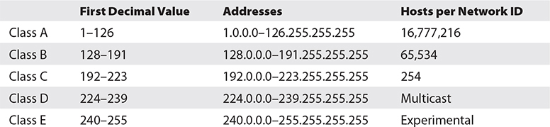
NOTE This class system has long since gone the way of the dodo, but techs do still use these classes as shorthand for the private address ranges that organizations and households worldwide use for their internal networks. We’ll take a closer look at these private address ranges in the “Special IP Addresses” section at the end of the chapter.
A typical Class A network block, for example, had a network ID starting between 1 and 126; hosts on that network had only the first octet in common, with any numbers for the other three octets. Having three octets to use for hosts means an enormous number of possible hosts, over 16 million different combinations. The corresponding subnet mask for a Class A network block would be 255.0.0.0, leaving 24 bits for host IDs.
EXAM TIP CompTIA and many techs use the term classful to describe the traditional class blocks. Thus, you’ll see classful A, B, C, D, and E addressing on the exam. Keep reading and this will make sense.
Do you remember binary math? 224 = 16,777,216. Because the host can’t use all zeroes or all ones (those are reserved for the network ID and broadcast address, respectively), you should subtract two from the final number to get the available host IDs (both in this example, and in the ones below).
NOTE The Internet Corporation for Assigned Names and Numbers (ICANN) indirectly manages IANA through an affiliate organization, Public Technical Identifiers (PTI). PTI was formed to perform IANA’s technical work; ICANN is more focused on policy.
A Class B network block, which would correspond to a subnet mask of 255.255.0.0, used the first two octets to define the network ID. This left two octets to define host IDs, meaning each Class B network ID could have up to 216 – 2 = 65,534 different hosts. A Class C network block used the first three octets to define only the network ID. All hosts in network 192.168.35.0, for example, would have all three first numbers in common. Only the last octet defined the host IDs, leaving just 28 – 2 = 254 possible unique addresses. The subnet mask corresponding to a Class C block is 255.255.255.0.
Multicast class blocks are used for one-to-many communication (though we don’t really refer to them as classes anymore), such as in streaming video conferencing. There are four ways to send a packet: a broadcast, which is where every computer on the LAN hears the message; a unicast, where one computer sends a message directly to another; an anycast, where multiple computers share a single address and routers direct messages to the closest computer; and a multicast, where a single computer sends a message to a group of interested computers. Routers use multicast to talk to each other. Experimental addresses are reserved and never used except for occasional experimental reasons. These were originally called Reserved addresses.
EXAM TIP Make sure you memorize the IP class blocks! You should be able to look at any IP address and know its class block. Here’s a trick to help: The first binary octet of a Class A address always begins with a 0 (0xxxxxxx); for Class B, it begins with a 10 (10xxxxxx); for Class C, with 110 (110xxxxx); for Class D, with 1110 (1110xxxx); and for Class E, it begins with 1111 (1111xxxx).
IP class blocks worked well for the first few years of the Internet but quickly ran into trouble because they didn’t quite fit for everyone. Early on, IANA gave away IP network blocks rather generously, perhaps too generously. Over time, unallocated IP addresses became scarce. Additionally, the IP class block concept didn’t scale well. If an organization needed 2000 IP addresses, for example, it either had to take a single Class B network block (wasting 63,000 addresses) or eight Class C blocks. As a result, a new method of generating blocks of IP addresses, called Classless Inter-Domain Routing (CIDR), was developed.
CIDR and Subnetting
The foundation of CIDR is a concept called subnetting: taking a single class of IP addresses and chopping it up into multiple smaller groups called subnets. Once upon a time, subnetting was just One Weird Trick organizations used to break up and organize their networks. CIDR makes it possible to extend this subnetting approach to the Internet as a whole. RIRs and ISPs play an important role in taking blocks of IP addresses, breaking them up into multiple subnets, and assigning those subnets to smaller organizations. Subnetting and CIDR have been around for quite a long time now and are a critical part of all but the smallest TCP/IP networks. Let’s first discuss subnetting and then visit CIDR.
Subnetting
Subnetting enables a much more efficient use of IP addresses compared to class blocks. It also enables you to separate a network for security (separating a bank of publicly accessible computers from your more private computers) and for bandwidth control (separating a heavily used LAN from one that’s not so heavily used).
EXAM TIP You need to know how to subnet to pass the CompTIA Network+ exam.
The cornerstone to subnetting lies in the subnet mask. You take an existing /8, /16, or /24 subnet and extend the subnet mask by replacing zeroes with ones. For example, let’s say you have a café with public Wi-Fi and two computers in the back office for accounting and monitoring the shop’s security cameras (Figure 6-28). Your network ID is 192.168.4.0/24. You want to prevent people who are using the public systems from accessing your private machines, so you decide to set up two physically separate LANs—one for the guests, and one for your own systems—and then assign a subnet to each LAN.

Figure 6-28 Layout of the network
You need to keep two things in mind about subnetting. First, start with the given subnet mask and move it to the right until you have the number of subnets you need. Second, forget the dots. They no longer define the subnets.
Never try to subnet without first converting to binary. Too many techs are what I call “victims of the dots.” They are so used to working only with class blocks that they forget there’s more to subnets than just /8, /16, and /24 networks. There is no reason network IDs must end on the dots. The computers, at least, think it’s perfectly fine to have subnets that end at points between the periods, such as /26, /27, or even /22. The trick here is to stop thinking about network IDs and subnet masks just in their dotted decimal format and instead return to thinking of them as binary numbers.
NOTE Classful subnets were always /8, /16, or /24.
Let’s begin subnetting the café’s network of 192.168.4.0/24. Start by changing a zero to a one on the subnet mask so the /24 becomes a /25 subnet:
11111111111111111111111110000000
Calculating Hosts
Before going even one step further, you need to answer this question: On a /24 network, how many hosts can you have? If you used dotted decimal notation, you might answer as follows:
192.168.4.1 to 192.168.4.254 = 254 hosts
But do this from the binary instead. In a /24 network, you have eight zeroes that can be the host ID:
00000001 to 11111110 = 254
There’s a simple piece of math here: 2x – 2, where x represents the number of zeroes in the subnet mask. Subtract two for the network ID and broadcast address, just as when calculating the number of hosts in classful addressing.
28 – 2 = 254
If you remember this simple formula, you can always determine the number of hosts for a given subnet. This is critical! Memorize this!
EXAM TIP Use this formula to know precisely the number of hosts for a given subnet: 2x − 2, where x = number of zeroes in the subnet mask.
If you have a /16 subnet mask on your network, what is the maximum number of hosts you can have on that network?
1. Because a subnet mask always has 32 digits, a /16 subnet means you have 16 zeroes left after the 16 ones.
2. 216 – 2 = 65,534 total hosts.
If you have a /26 subnet mask on your network, what is the maximum number of hosts you can have on that network?
1. Because a subnet mask always has 32 digits, a /26 subnet means you have 6 zeroes left after the 26 ones.
2. 26 – 2 = 62 total hosts.
Excellent! Knowing how to determine the number of hosts for a subnet mask will help you tremendously, as you’ll see in a moment.
Making a Subnet
Let’s now make a subnet. All subnetting begins with a single network ID. In this scenario, you need to convert the 192.168.4.0/24 network ID for the café into three network IDs: one for the public computers, one for the private computers, and one for the wireless clients.
NOTE You cannot subnet without using binary!
The primary tool for subnetting is the existing subnet mask. Write it out in binary. Place a line at the end of the ones, as shown in Figure 6-29.

Figure 6-29 Step 1 in subnetting
Now draw a second line one digit to the right, as shown in Figure 6-30. You’ve now separated the subnet mask into three areas that I call (from left to right) the default subnet mask (DSM), the network ID extension (NE), and the hosts (H). These are not industry terms, so you won’t see them on the CompTIA Network+ exam, but they’re a handy Mike Trick that makes the process of subnetting a lot easier.
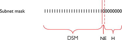
Figure 6-30 Organizing the subnet mask
You now have a /25 subnet mask. At this point, most people first learning how to subnet start to freak out. They’re challenged by the idea that a subnet mask of /25 isn’t going to fit into one of the three pretty subnets of 255.0.0.0, 255.255.0.0, or 255.255.255.0. They think, “That can’t be right! Subnet masks are made of only 255s and 0s.” That’s not correct. A subnet mask is a string of ones followed by a string of zeroes. People only convert the masks into dotted decimal to enter them into computers. So, convert /25 into dotted decimal. First write out 25 ones, followed by 7 zeroes. (Remember, subnet masks are always 32 binary digits long.)
11111111111111111111111110000000
Insert the periods in between every eight digits:
11111111.11111111.11111111.10000000
Then convert them to dotted decimal:
255.255.255.128
Get used to the idea of subnet masks that use more than 255s and 0s. Here are some examples of perfectly legitimate subnet masks. Try converting these to binary to see for yourself:
255.255.255.224
255.255.128.0
255.248.0.0
Calculating Subnets
When you subnet a network ID, you need to follow the rules and conventions dictated by the good folks who developed TCP/IP to ensure that your new subnets can interact properly with each other and with larger networks. All you need to remember for subnetting is this: start with a beginning subnet mask and extend the subnet extension until you have the number of subnets you need. The formula for determining how many subnets you create is 2y, where y is the number of bits you add to the subnet mask.
Let’s practice this a few times. Figure 6-31 shows a starting subnet of 255.255.255.0. If you move the network ID extension over one, it’s only a single digit, 21.

Figure 6-31 Initial subnetting
That single digit is only a zero or a one, which gives you two subnets. You have only one problem—the café needs three subnets, not just two! So, let’s take /24 and subnet it down to /26. Extending the network ID by two digits creates four new network IDs, 22 = 4. To see each of these network IDs, first convert the original network ID—192.168.4.0—into binary. Then add the four different network ID extensions to the end, as shown in Figure 6-32.
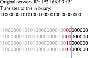
Figure 6-32 Creating the new network IDs
Figure 6-33 shows all the IP addresses for each of the four new network IDs.
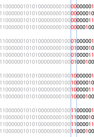
Figure 6-33 New network ID address ranges
Now convert these four network IDs back to dotted decimal:
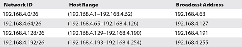
Congratulations! You’ve just taken a single network ID, 192.168.4.0/24, and subnetted it into four new network IDs! Figure 6-34 shows how you can use these new network IDs in a network.

Figure 6-34 Three networks using the new network IDs
You may notice that the café only needs three subnets, but you created four—you’re wasting one. Because subnets are created by powers of two, you will often create more subnets than you need—welcome to subnetting.
NOTE If wasting subnets seems contrary to the goal of efficient use, keep in mind that subnetting has two goals: efficiency and making multiple network IDs from a single network ID. This example is geared more toward the latter goal.
For a little more subnetting practice, let’s create eight subnets on a /27 network. First, move the NE over three digits (Figure 6-35).
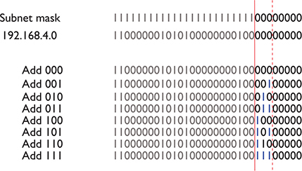
Figure 6-35 Moving the network ID extension three digits
To help you visualize the address range, I’ll calculate the first two subnets—using 000 and 001 (Figure 6-36). Please do the other six for practice.

Figure 6-36 Two of the eight network ID address ranges
Note that in this case you only get 25 – 2 = 30 hosts per network ID! These better be small networks!
Converting these to dotted decimal, you get the following:
192.168.4.0/27 (192.168.4.1–192.168.4.30)
192.168.4.32/27 (192.168.4.33–192.168.4.62)
192.168.4.64/27 (192.168.4.65–192.168.4.94)
192.168.4.96/27 (192.168.4.97–192.168.4.126)
192.168.4.128/27 (192.168.4.129–192.168.4.158)
192.168.4.160/27 (192.168.4.161–192.168.4.190)
192.168.4.192/27 (192.168.4.193–192.168.4.222)
192.168.4.224/27 (192.168.4.225–192.168.4.254)
These two examples began with a Class C address. However, you can begin with any starting network ID. Nothing changes about the process you just learned.
EXAM TIP CompTIA and many techs refer to a CIDR address as a classless address, meaning the subnet used does not conform to the big three on the classful side: A, B, or C. When you see that term on the exam, you’ll know you should look for subnetting.
The examples used in this introduction to subnetting took a single network ID and chopped it into identically sized subnets. The simplest subnetting example, in other words, created four /26 subnets from one /24 network ID. You can vary the size of the subnets created, however, with classless variable-length subnet masking (VLSM). ISPs might do this to accommodate different customer needs, taking a single network ID and handing out custom subnets. John’s tiny company might get a /30 subnet; Jennie’s larger company might get a /26 subnet to accommodate many more users.
NOTE Assuming you could still order real, unique, ready-for-the-Internet IP addresses from your local ISP (you can’t), you’d invariably get a classless set of IP addresses. More importantly, when you work with clients, you need to be able to explain why their subnet mask is 255.255.255.192, when all the books they read tell them it should be 255.255.255.0! See Chapter 12 for the scoop on IPv6, the addressing scheme gradually replacing IPv4.
Manual Dotted Decimal to Binary Conversion
The best way to convert from dotted decimal to binary and back is to use a calculator. It’s easy, fast, and accurate. There’s always a chance, however, that you may find yourself in a situation where you need to convert without a calculator. Fortunately, manual conversion, although a bit tedious, is also easy. You just have to remember a single number: 128.
Take a piece of paper and write the number 128 in the top-left corner. Now, what is half of 128? That’s right, 64. Write 64 next to 128. Now keep dividing the previous number in half until you get to the number 1. The result will look like this:
![]()
Notice that you have eight numbers. Each of these numbers corresponds to a position of one of the eight binary digits. To convert an 8-bit value to dotted decimal, just take the binary value and put the numbers under the corresponding eight digits. Wherever there’s a 1, add that decimal value.
Let’s take the binary value 10010110 into decimal. Write down the numbers as shown, and then write the binary values underneath each corresponding decimal number:
![]()
Add the decimal values that have a 1 underneath:
128 + 16 + 4 + 2 = 150
Converting from decimal to binary is a bit more of a challenge. You still start with a line of decimal numbers starting with 128, but this time, you place the decimal value above. If the number you’re trying to convert is greater than or equal to the number underneath, subtract it and place a 1 underneath that value. If not, then place a 0 under it and move the number to the next position to the right. Let’s give this a try by converting 221 to binary. Begin by placing 221 over the 128:
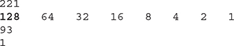
Now place the remainder, 93, over the 64:
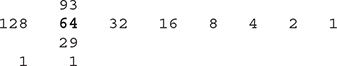
Place the remainder, 29, over the 32. The number 29 is less than 32, so place a 0 underneath the 32 and move 29 again, over the 16:
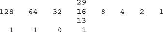
Then move to the 8:
Then the 4:
Then the 2. The number 1 is less than 2, so drop a 0 underneath and move to 1:
![]()
Finally, the 1; 1 is equal to 1, so put a 1 underneath and you’re done. The number 221 in decimal is equal to 11011101 in binary.
EXAM TIP Make sure you can manually convert decimal to binary and binary to decimal.
CIDR: Key Takeaways
Subnetting is a competency everyone who’s serious about networking understands in detail—it’s a clear separation between those who know networks and those who do not. For the CompTIA Network+ exam, you need to be able to take any existing network ID and break it down into a given number of subnets. You need to know how many hosts the resulting network IDs possess. You need to be able to calculate the IP addresses and the new subnet masks for each of the new network IDs. You need to think of subnets in CIDR terms like /10, /22, /26, and so on.
EXAM TIP Expect to see a question or two on the CompTIA Network+ exam that asks you to compare Classless Inter-Domain Routing (CIDR) notation (IPv4 vs. IPv6). The former should be familiar, with “notation” meaning the four octets and a /# for the subnet mask. See Chapter 12 for full coverage of IPv6.
You’ve done well, my little Padawan. Subnetting takes a little getting used to. Go take a break. Take a walk. Play some World of Warcraft (I just can’t quit!), Fortnite, or maybe a few laps in Forza Horizon. After a good mental break, dive back into subnetting and practice. Take any old network ID and practice making multiple subnets—lots of subnets!
IP Address Assignment
Whew! After all that subnetting, you’ve reached the point where it’s time to start using some IP addresses. That is, after all, the goal of going through all that pain. There are two ways to configure a host’s IP settings (for our purposes here, its IP address, subnet mask, and default gateway): either by typing in all the information (called static addressing) or by having a server program running on a system that automatically passes out all the IP information to systems as they boot up on or connect to a network (called dynamic addressing). Additionally, you must learn about several specialty IP addresses that have unique meanings in the IP world to make this all work.
EXAM TIP The CompTIA Network+ exam objectives use the terms static assignment and dynamic assignment to describe these static and dynamic addressing methods for setting device IP addresses.
Static IP Addressing
Static addressing means typing all the IP information into each of your hosts. But before you type in anything, you must answer two questions: What are you typing in and where do you type it? Let’s visualize a four-node network like the one shown in Figure 6-37.
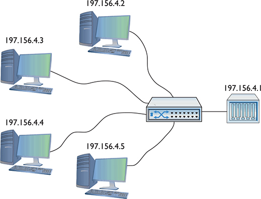
Figure 6-37 A small network
To make this network function, each computer must have an IP address, a subnet mask, and a default gateway. First, decide what network ID to use. In the old days, your ISP gave you a block of IP addresses to use. Assume that’s still the method and you’ve been allocated a Class C network block for 197.156.4.0/24. The first rule of Internet addressing is…no one talks about Internet addressing. Actually, we can maul the Fight Club reference and instead say, “The first rule of Internet addressing is that you can do whatever you want with your own network ID.” There are no rules other than to make sure every computer gets a legit IP address and subnet mask for your network ID and make sure every IP address is unique. You don’t have to use the numbers in order, you don’t have to give the default gateway the 192.156.4.1 address—you can do it any way you want. That said, most networks follow a common set of principles:
1. Give the default gateway the first or last IP address in the network ID.
2. Try to use the remaining IP addresses in sequential order.
3. Try to separate servers from clients. For example, servers could have the IP addresses 197.156.4.10 to 197.156.4.19, whereas the clients range from 197.156.4.200 to 197.156.4.254.
4. Document whatever you choose to do so the person who comes after you understands.
These principles have become unofficial standards for network techs, and following them will make you very popular with whoever has to manage your network in the future.
Now you can give each of the computers an IP address, subnet mask, and default gateway. Every operating system has some method for you to enter the static IP information. Let’s look at how the same configuration looks on Windows, macOS, and Ubuntu Linux. In Windows, you use the Internet Protocol Version 4 (TCP/IPv4) Properties dialog (the older way) or the Edit IP Settings dialog in the Settings app, as shown in Figure 6-38.
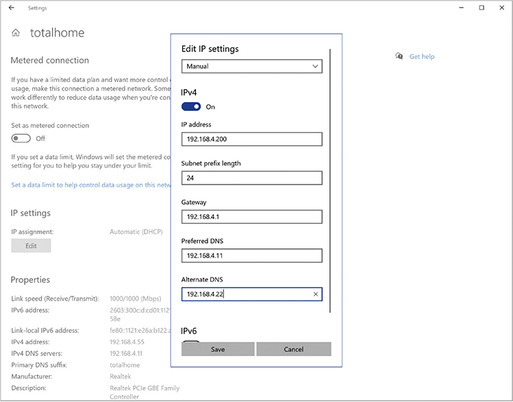
Figure 6-38 Entering static IP information in Windows Settings
In macOS, run the Network utility in System Preferences to enter in the IP information (Figure 6-39).
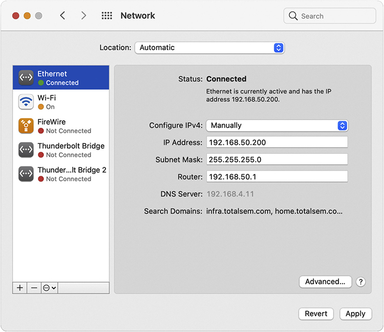
Figure 6-39 Entering static IP information in the macOS Network utility
The universal tool for entering IP information on UNIX/Linux systems is the command-line ip command:
# ip addr add 192.168.4.10 dev eth1
EXAM TIP You might get a question about setting a static IP address in Linux where ip isn’t one of the choices. Go with the deprecated ifconfig command in that case.
A warning about setting static IP addresses with ip: any address entered will not be permanent and will be lost on reboot. To make the new IP address permanent, you need to find and edit your network configuration files. Fortunately, modern distros make your life a bit easier. Almost every flavor of UNIX/Linux comes with some handy graphical program, such as Network Configuration in the popular Ubuntu Linux distro (Figure 6-40).
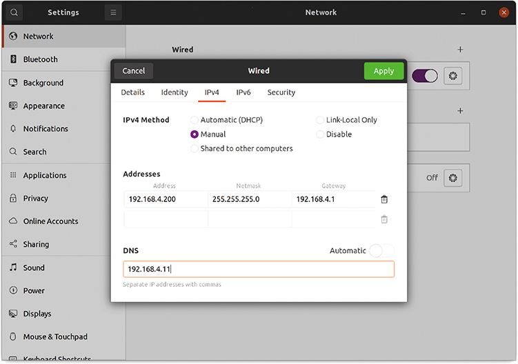
Figure 6-40 Entering static IP information in the Ubuntu Network Configuration utility
![]()
SIM Check out the excellent “Static IP in Linux” Show! over at https://totalsem.com/008. It’ll take you through the process of setting up a static IP in a typical Linux distro.
Once you’ve added the IP information for at least two systems, you should always verify using the ping command. Figure 6-41 shows what to expect if the system is reachable and what you’ll see if there’s a problem. If you’ve entered an IP address and your ping is not successful, first check your IP settings. Odds are good you made a typo.
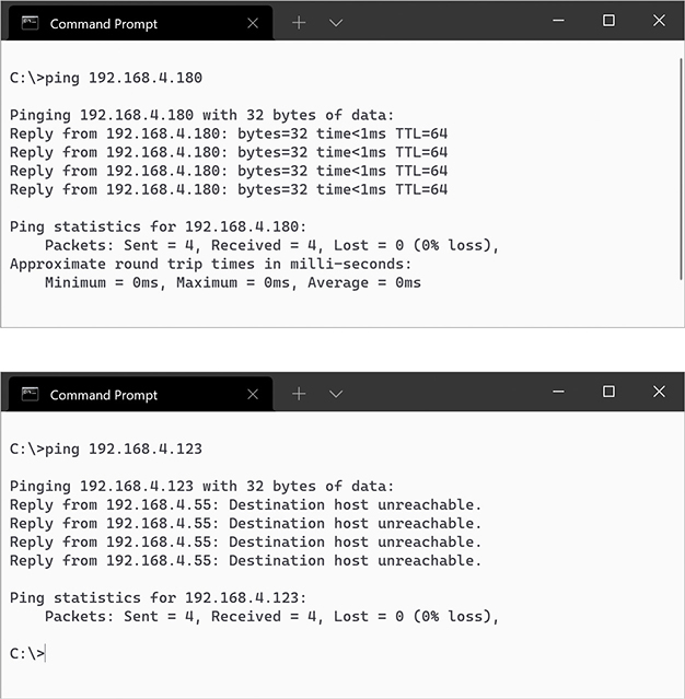
Figure 6-41 Two pings (successful ping on top, unsuccessful ping on bottom)

CAUTION Always verify with ping—it’s too easy to make a typo when entering static IP addresses.
Otherwise, check your connections, driver, and so forth. Static addressing has been around for a long time and is still heavily used for more-critical systems on your network. Static addressing poses one big problem, however: making any changes to the network is a serious pain. Most systems today use a far easier and more flexible method to get their IP information: dynamic IP addressing.
Dynamic IP Addressing
Dynamic IP addressing via the Dynamic Host Configuration Protocol (DHCP) automatically assigns an IP address whenever a computer connects to the network. DHCP works very simply. Any network using DHCP consists of a DHCP server and DHCP clients. Clients request IP information from DHCP servers. DHCP servers in turn pass out IP information to the clients (Figure 6-42). In most networks, most hosts—desktops, laptops, and mobile devices—are DHCP clients. Most networks have a single DHCP server. It is often built into a router for small office/home office (SOHO) networks, but in enterprise networks the DHCP server program may be one of many running on a rack-mounted server.
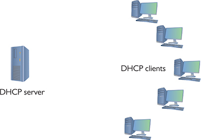
Figure 6-42 DHCP server and clients
How DHCP Works
When a DHCP client boots up, it automatically broadcasts a DHCP Discover message. This DHCP Discover message asks, “Are there any DHCP servers out there?” (See Figure 6-43.)

Figure 6-43 Computer sending out a DHCP Discover message
The DHCP server hears the request and then sends the DHCP client a DHCP Offer message (Figure 6-44). This message includes an IP address, subnet mask, and gateway (as well as other information not yet covered in this book).
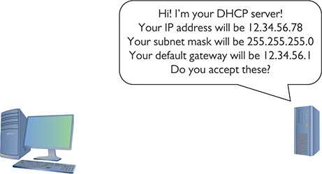
Figure 6-44 DHCP server sending a DHCP Offer message
The DHCP client sends out a DHCP Request—a poor name choice as it is really accepting the offer—verifying that the offer is still valid. The DHCP Request is very important as it tells the network that this client is accepting IP information from this and only this DHCP server.
The DHCP server then sends a DHCP ACK (Acknowledgment) and lists the client’s MAC address as well as the IP information given to the DHCP client in a database (Figure 6-45).

Figure 6-45 DHCP Request and DHCP Acknowledgment
At the end of this four-step DHCP dance (called the DHCP four-way handshake, or DORA, for Discover, Offer, Request, and Acknowledgment), the DHCP client gets a DHCP lease from the pool of available leases. A DHCP lease is set for a fixed amount of time, often one to eight days. Near the end of the lease time, the DHCP client sends another DHCP Request message.
The DHCP server looks at the MAC address information and always gives the DHCP client the same IP information, including the same IP address.
NOTE Using the acronym DORA—for Discover, Offer, Request, and Acknowledgment—will help you remember the DHCP four-way handshake.
Configuring DHCP
A properly functioning DHCP network requires properly configured DHCP clients and DHCP servers. Let’s look at the configuration of both a client and a server.
EXAM TIP DHCP servers use UDP port 67 and DHCP clients use port 68. And yes, memorize the numbers.
Configuring a DHCP client is simple and, in most cases, every host is preconfigured as a DHCP client by default. Every OS has some method to tell the computer to use DHCP, as in the Windows example shown in Figure 6-46.
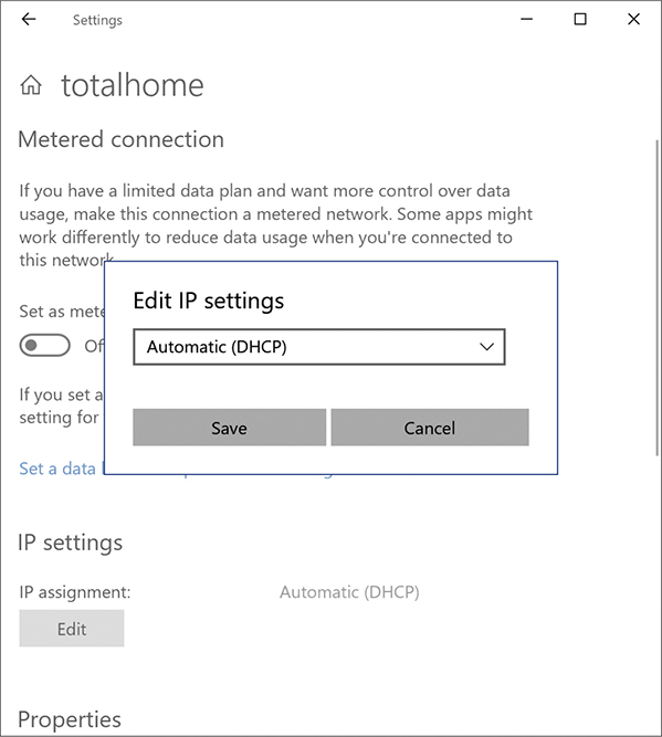
Figure 6-46 Setting up for DHCP
![]()
SIM Check out the excellent Chapter 6 “DHCP Client Setup” Click! over at https://totalsem.com/008. It walks you through the process of setting up DHCP in Windows.
DHCP servers, on the other hand, require some hands-on configuration. Consider what a DHCP server requires:
• It needs a pool of legitimate IP addresses that it can pass out to clients.
• It needs to know the subnet mask for the network.
• It needs to know the IP address for the default gateway for the network.
When a technician installs a range (or pool) of IP addresses, this is called a DHCP scope. Figure 6-47 shows a typical home router’s DHCP settings. Note that it is passing out a DHCP scope of 192.168.50.2 to 192.168.50.254. It also passes out other information, known as scope options, that cover many choices, such as the default gateway, DNS server, Network Time server, and so on. So why is the Default Gateway setting blank? This home router assumes that it is the default gateway (a fairly safe guess), so it automatically passes out its own IP address (configured on a different screen).

Figure 6-47 SOHO DHCP server main screen
Note the settings to enable or disable the DHCP server in Figure 6-47. Since in all but the rarest cases there should only be one DHCP server on a small LAN, it’s handy to have an option to disable the DHCP server on this router.
DHCP relay is a bit more complex, so let’s take some time to understand this powerful feature.
DHCP Relay DHCP’s initial four-way DORA handshake relies on broadcasting to work. (When a client renews its DHCP lease, everything’s unicast because the client already has a valid IP address and knows the DHCP server’s IP address.) Broadcasting works well within a broadcast domain, but all routers block broadcast traffic (if they didn’t, the entire Internet would consist of nothing but broadcasts). See Figure 6-48.
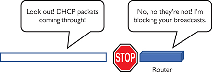
Figure 6-48 Routers block DHCP broadcasts.
There are situations, however, where it’s difficult or impractical to place a DHCP server in the same LAN as the DHCP clients. A single organization with many individual LANs would also need many individual DHCP servers, an administrative nightmare. These cases require the use of a DHCP relay (or DHCP relay agent), which enables a router to accept DHCP broadcasts from clients and then use UDP forwarding to send them on via unicast addresses directly to the DHCP server (Figure 6-49).
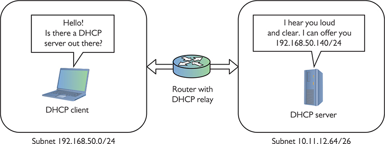
Figure 6-49 DHCP relays enable DHCP traffic to cross routers.
To make a DHCP relay–capable device work, you must give the relay the IP address of the real DHCP server. This address is variously known as the IP helper address or UDP helper address. (The approach you’ll need to configure this can vary widely across routers.)
Reservation Many networks contain hosts that we need to be able to reach at a stable IP address. Some devices, such as routers, switches, file servers, printers, and cameras, should never use dynamic IP addresses; users need a permanent, fixed IP address to locate these devices easily (Figure 6-50).
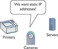
Figure 6-50 Many devices do not need DHCP.
When you set up a new network, it’s a good idea to set aside IP addresses for these devices and then subdivide the set-aside addresses into chunks for each kind of device. You might, for example, set aside distinct address ranges for your network hardware, servers, workstations, printers, and Wi-Fi clients. Part of deciding how to carve up these addresses is deciding whether each range should be statically or dynamically assigned.
Where the rubber meets the road, there are two approaches to managing the static addresses. The first approach is to reserve the IP addresses to keep DHCP from assigning them and configure each host with a static address. One way to “reserve” some is to just reduce the size of the pool of assignable addresses to avoid that range. The other way is to knock out some of the addresses inside the pool by creating an IP exclusion range. Figure 6-51 shows the configuration screen for setting an IP exclusion range in the built-in DHCP tool that comes with Windows Server.
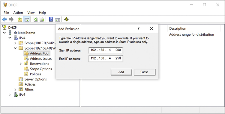
Figure 6-51 DHCP Server configuration screen showing IP exclusion range
The other approach is to use the DHCP server to set up MAC reservations—enabling DHCP to lease the same address to the same host each time. From then on, any time the system with that MAC address makes a DHCP Request, the reservation guarantees that that system will get the same IP address. Figure 6-52 shows Windows DHCP Server configuring a MAC reservation.
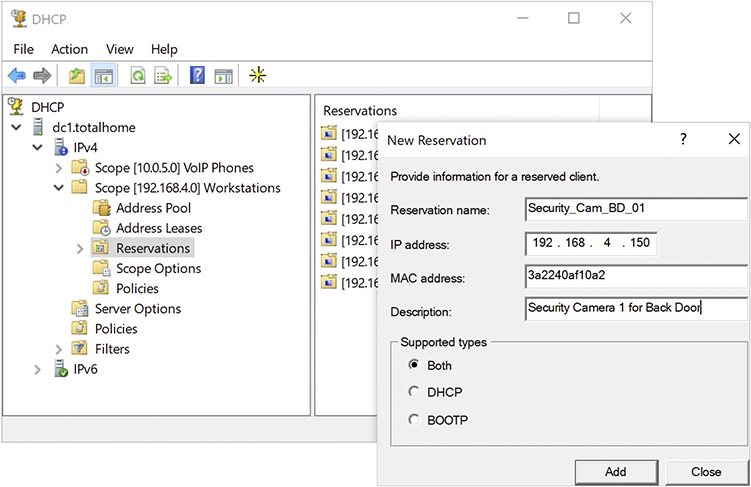
Figure 6-52 DHCP Server configuration screen showing a MAC reservation
Figure 6-53 shows Windows DHCP Server’s general configuration screen. Note the single scope. Figure 6-54 shows the same DHCP Server tool, in this case detailing the Scope Options. At this point, you’re probably not sure what any of these options are for. Don’t worry. I’ll return to these topics in later chapters.
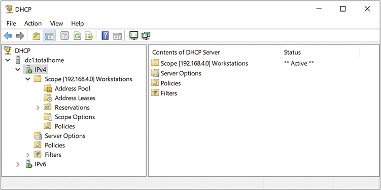
Figure 6-53 DHCP Server configuration screen showing single scope
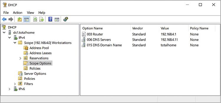
Figure 6-54 DHCP Server Scope Options
Living with DHCP
DHCP is very convenient and, as such, very popular. It’s also completely invisible to users—when it works. They just turn on their devices, DHCP does its job in the background, and they can access Netflix or the file server. This transparency comes at a cost; when it breaks, the user may be clueless. Their systems won’t get IP information and they won’t get on the network. Taking the time to understand a few basic problems that come up with DHCP will help you quickly track down the cause.
No DHCP Server The single biggest issue is when a DHCP client tries to get a DHCP address and fails. You’ll know when this happens because the operating system will post some form of error telling you there’s a problem (Figure 6-55) and the DHCP client will have a rather strange address in the 169.254.0.0/16 network ID.

Figure 6-55 DHCP error in macOS
This special IP address is generated by a version of zero-configuration networking (zeroconf). Microsoft’s implementation is called Automatic Private IP Addressing (APIPA). (That’s the one you’ll see on the exam.)
All DHCP clients are designed to generate an APIPA address automatically if they do not receive a response to a DHCP Discover message. The client only generates the last two octets of an APIPA address. This at least allows the dynamic clients on a single network to continue to communicate with each other because they are on the same network ID.
Unfortunately, APIPA cannot issue a default gateway, so you’ll never get on the Internet using APIPA. That provides a huge clue to a DHCP problem scenario: you can communicate with other computers on your network that came up after the DHCP server went down, but you can’t get to the Internet or access computers that retain the DHCP-given address.
EXAM TIP Systems that use static IP addressing can never have DHCP problems.
If you can’t get to the Internet, use whatever tool your OS provides to check your IP address. If it’s an APIPA address, you know instantly that you have a DHCP problem. First, try to reestablish the lease manually. Every OS has some way to do this. In Windows, you can type the following command:
ipconfig /renew
With macOS, go to System Preferences and use the Network utility (Figure 6-56).

Figure 6-56 Network utility in System Preferences
Sometimes you might find yourself in a situation where your computer gets confused and won’t grab an IP address no matter what you try. In these cases, you should first force the computer to release its lease. In Windows, get to a command prompt and type these two commands; follow each by pressing ENTER:
ipconfig /release
ipconfig /renew
In macOS, use the ifconfig command to release and renew a DHCP address. Here’s the syntax to release:
sudo ifconfig eth0 down
And here’s the syntax to renew:
sudo ifconfig eth0 up
EXAM TIP Make sure you know how to configure your computers to use static IP addressing and know that you use ping to ensure they can communicate. For dynamic IP addressing, make sure you know DHCP. Understand that each client must have some way to “turn on” DHCP. Also understand the concept of a DHCP client and a DHCP server. Be comfortable with APIPA and releasing and renewing a lease on a client.
Linux can use the deprecated ifconfig command with the same syntax as shown for macOS, but a better tool is dhclient. Here’s the syntax to release, followed by the syntax to renew:
sudo dhclient -r
sudo dhclient
EXAM TIP You might see a question on the CompTIA Network+ exam that asks you to contrast automatically generated IP addresses in IPv4 vs. IPv6. A zeroconf address in IPv4 points to a DHCP failure. IPv6 always generates IP addresses automatically. These are called link-local addresses and we’ll go into detail on them in Chapter 12. Just note that they’re normal and expected in IPv6.
Multiple DHCP Servers A lone DHCP server is a single point of failure for a network. If this server dies, at best no one can get on the Internet; at worst, no one can do anything at all. To avoid this problem, bigger networks—think enterprise—run more than one DHCP server. That way it doesn’t matter which DHCP server answers. You can do this in a couple ways. Assume you have a network ID of 172.13.14.0. You could configure the two DHCP servers as such:
DHCP Server 1: Scope 172.13.14.200–172.13.14.225
DHCP Server 2: Scope 172.13.14.226–172.13.14.250
Each DHCP server would still use the same subnet mask, default gateway, and so on.
Running two independent DHCP servers doubles the administrative load, so a far more elegant solution is DHCP failover. In DHCP failover, two—and only two—DHCP servers work together to provide DHCP for the network. First widely implemented in Windows Server 2012, a DHCP failover pair consists of a primary DHCP server and a secondary DHCP server. As opposed to two independent DHCP servers, the DHCP failover pair shares a single scope. If either fails, the other picks up the load and the end users never notice a thing. DHCP failover is quite common in large networks.
Rogue DHCP Server A DHCP client will accept IP information from the first DHCP server that responds, creating a bit of a problem. It’s too easy to add another DHCP server to a network, passing out incorrect IP information to clients. This is called a rogue DHCP server. Rogues happen in one of two ways: someone in the organization brings in a home router and innocently plugs it into the network or someone evil is trying to attack your network. In either case, a rogue DHCP server is bad.
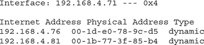
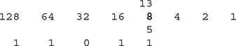
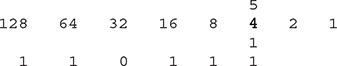
An unintentional rogue server is usually easy to detect. Consider this scenario. A legitimate user in your network plugs a home router into a wall outlet in your location with the desire to provide a wireless network for their little corner of the world. Sadly, the router also has a DHCP server running by default. This DHCP server is invariably running a default IP address range such as 192.168.1.0/24, and your network ID should be anything but this default. As new DHCP clients request leases, the rogue DHCP server might respond before the legitimate DHCP server. Then the client can’t get on the Internet or access local network resources. Anytime a network administrator notices that some users can access resources and some cannot, it’s time to check for a rogue DHCP server. Usually a quick ipconfig will show DHCP clients with incorrect network IDs.
Let’s assume that your network ID is 10.11.12.0/24. A user complains that they can’t get on the Internet. You go to the user’s machine, run the ipconfig command, and see the following:
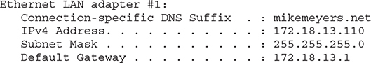
A good network administrator would quickly see that this system is gathering incorrect DHCP information from…somewhere. That somewhere is a rogue DHCP server.
Malicious rogue DHCP servers can be tougher to detect if they give out IP addresses in the same scope as the legitimate DHCP server, but change the default gateway. This enables the rogue server to intercept or capture incoming and outgoing traffic. What it does with this information depends on the nature of the attack. See Chapter 19 for the scoop on bad people doing bad things to good networks.
NOTE Good network admins always know their network IDs!
Special IP Addresses
The folks who invented TCP/IP created several special IP addresses you need to know about. The first special address is 127.0.0.1—the loopback address. When you tell a device to send data to 127.0.0.1, you’re telling that device to send the packets to itself. The loopback address has several uses. One of the most common is to use it with the ping command. I use the command ping 127.0.0.1 to test a computer’s network stack.
EXAM TIP Even though, by convention, you use 127.0.0.1 as the loopback address, the entire 127.0.0.0/8 subnet is reserved for loopback addresses! You can use any address in the 127.0.0.0/8 subnet as a loopback address.
Lots of folks use TCP/IP in networks that either aren’t connected to the Internet or include computers they want to hide from the rest of the Internet. The Engineering Task Force (IETF) set out specific ranges of IP addresses for such uses, known as private IP addresses, in RFC1918. (RFC is a Request for Comments; RFCs are used to define just about everything involving computer networking.) All routers block private IP addresses. Those addresses can never be used on the Internet, making them a handy way to hide systems. Anyone can use these private IP addresses, but they’re useless for systems that need to access the Internet—unless you use the mysterious and powerful NAT, which I’ll discuss in the next chapter. (Bet you’re dying to learn about NAT now!) For the moment, however, let’s just look at the ranges of addresses that are designated as private IP addresses:
• 10.0.0.0 through 10.255.255.255 (1 Class A network block)
• 172.16.0.0 through 172.31.255.255 (16 Class B network blocks)
• 192.168.0.0 through 192.168.255.255 (256 Class C network blocks)
All other IP addresses are public IP addresses.
EXAM TIP Make sure you can quickly tell the difference between a public IP address and a private IP address for the CompTIA Network+ exam. The objectives mention the distinction as public vs. private.
Chapter Review
Questions
1. What is the result of converting 11110000.10111001.00001000.01100111 to dotted decimal notation?
A. 4.5.1.5
B. 240.185.8.103
C. 15.157.16.230
D. 103.8.185.240
2. Eric sits down at a client’s Windows computer that’s having some network connectivity issues. He wants to start troubleshooting by viewing both the system’s IP address and MAC address. What command should he use?
A. ifconfig
B. ip addr
C. ipconfig
D. ipconfig /all
3. Which of the following describe IPv4? (Select three.)
A. Uses decimal, not hexadecimal numbers
B. Uses periods, not colons, as separators
C. Uses four octets
D. Uses eight sets of characters
4. What is the result of converting 192.168.0.1 to binary?
A. 11000000.10101000.00000000.00000001
B. 11000000.10101000.00000000.10000000
C. 11000000.10101000.00000000.1
D. 11.10101.0.1
5. Which of the following are not valid IP addresses to assign to a Windows-based system? (Select two.)
A. 10.1.1.1/24
B. 127.0.0.1/24
C. 250.250.250.255/24
D. 192.168.0.1/24
6. Phyllis has a service ticket for one of the latest Apple Macs that’s having network connectivity problems. What command could she use to quickly see the IP address and MAC address for that computer?
A. ifconfig
B. ip addr
C. ipconfig
D. ipconfig /all
7. Which of the following is a valid Class C IP address?
A. 50.50.50.50
B. 100.100.100.100
C. 192.168.0.254
D. 250.250.250.250
8. What processes are used to take a single class of IP addresses and chop it up into multiple smaller groups? (Select two.)
A. CIDR
B. ping
C. Subnetting
D. Subnitting
9. Which statements about subnet masks are true? (Select two.)
A. Every network client has a unique subnet mask.
B. Every client on a network shares the same subnet mask.
C. A subnet mask consists of a string of zeroes followed by a string of ones.
D. A subnet mask consists of a string of ones followed by a string of zeroes.
10. In which order are packets created and sent when a client requests an IP address from a DHCP server?
A. DHCP Discover, DHCP Offer, DHCP Request, DHCP ACK
B. DHCP Discover, DHCP Request, DHCP Offer, DHCP ACK
C. DHCP Request, DHCP Offer, DHCP Discover, DHCP ACK
D. DHCP Request, DHCP Offer, DHCP ACK, DHCP Discover
Answers
1. B. 240.185.8.103 is the result of the conversion to dotted decimal notation.
2. D. In Windows, the ipconfig /all command and switch will show both the IP address and the MAC address of a system.
3. A, B, and C. IPv4 uses decimal numbers, uses periods as separators, and has four octets.
4. A. 11000000.10101000.00000000.00000001 is the binary conversion of 192.168.0.1.
5. B and C. The special reserved IP address 127.0.0.1 is called the loopback address and is used for testing, not assigning to computers. The IP address 250.250.250.255 falls in the Class E range, which isn’t assigned to hosts.
6. A. Using the ifconfig command on a macOS system shows the system’s IP address and MAC address.
7. C. The address 192.168.0.254 falls within the range of Class C addresses because it starts with an octet from 192 through 223.
8. A and C. Classless Inter-Domain Routing (CIDR) and subnetting enable you to take a single class of IP addresses and chop it up into multiple smaller groups called subnets.
9. B and D. Every client on a network shares the same subnet mask. Subnet masks consist of a string of ones followed by a string of zeroes.
10. A. DHCP Discover, DHCP Offer, DHCP Request, DHCP ACK (remember DORA) is the correct order.