▶ 13.4 Network Layer Cryptography
Network layer cryptography leaves enough of a packet in plaintext to allow routing through the internet, while still protecting the actual data as it travels between hosts. In the internet community, the standard network layer protocol is IPsec, the IP Security Protocol.
Evolution of Network Layer Encryption
IPsec is not the only network layer encryption protocol, nor is it the first. The DOD commissioned a network-layer encryption system for the ARPANET, called the “private line interface.” With the deployment of internet protocols, the NSA promoted a series of protocol standards, called the Secure Data Network System (SDNS), that included a protocol similar to IPsec called “Security Protocol 3” (SP3). However, that protocol was never widely used because it encountered deployment and interoperability problems. Moreover, the NSA initially discouraged distribution of the protocol specifications, making it hard to implement.
In the late 1980s, internet developers produced the Point-to-Point Protocol (PPP), for carrying IP traffic across serial lines, including dial-up modem connections. Microsoft and a group of other vendors adapted the protocol to use internet connections, as well as dial-up, and to provide cryptographic protection of its contents. PPTP, the new protocol, could connect Windows systems across the internet and cryptographically protect the connection.
Unfortunately, PPTP contained several design errors, similar to those in early versions of SSL. (For an example, return to Section 8.2.) However, SSL was promptly revised to eliminate the weaknesses, while flawed versions of PPTP remained in place and were supported for years. Products that supported PPTP eventually supported IPsec as a safer alternative.
IPsec was developed and standardized in the mid-1990s. Its development took advantage of lessons learned from the SDNS effort. The developers were familiar with the problems that arose in SSL and PPTP and did not repeat them in the IPsec design.
The principal application of IPsec is the VPN. A typical enterprise has a set of central services they provide exclusively to users on the company network. For security reasons, they block access to these servers from the internet. If the enterprise has two or more separate locations, the workers at those locations need to reach those central servers.
In pre-internet days, larger enterprises might lease a point-to-point connection between headquarters and its other major offices. This gave the offices access to computing resources at headquarters. Leased lines were expensive, however. VPNs provided a lower cost, internet-based alternative to leased lines. The VPN provided a way to exchange encrypted packets between sites.
FIGURE 13.22 illustrates a small VPN arrangement. The example shows an enterprise with one main office and one branch office. When people inside one of the offices send messages to the other office, the packets pass through a gateway connected to the internet. Outbound packets are encrypted and forwarded to the other office. Inbound encrypted packets from the internet are decrypted and delivered on the office LAN.

FIGURE 13.22 A small virtual private network.
The lower right-hand corner shows a mobile client, a device that may operate from one of many unpredictable locations. Many organizations also deploy VPN software on laptops and other mobile clients. This allows the client computer to connect to the enterprise LAN remotely and use its resources. The laptop encrypts the enterprise traffic itself. The enterprise gateway decrypts the laptop’s encrypted packets the same as packets from the other gateway.
The encrypting gateways provide proxy encryption for the hosts on the enterprise networks. The encryption protects the host traffic, but the hosts themselves don’t have to perform the encryption. This is shown in FIGURE 13.23.

FIGURE 13.23 IPsec gateway encrypts a packet.
Figure 13.23 shows packet handling in a network that uses an encrypting IPsec gateway. Traffic inside the network is in plaintext. When packets leave the site, they travel through the gateway. Packets destined for other VPN gateways are encrypted on the way out. Although the IP header remains in plaintext, the cryptography applies a keyed hash to protect the header from modification.
Because the endpoint hosts aren’t doing their own encryption, the gateways don’t provide end-to-end crypto. Moreover, the endpoints can’t be certain whether or not their traffic is being protected.
Figure 13.23 illustrates a benefit of moving the cryptography away from the application: We can easily off-load it onto other hardware. Some vendors offer SSL accelerator hardware for websites; no such products are offered for desktops. An IPsec gateway off-loads the cryptography from client and server alike. Not only are desktops relieved of the crypto processing overhead, but they are saved from key-management headaches as well.
Components of IPsec
IPsec itself focuses on data protection. Within IPsec, there are two generic types of protection:
Authentication using the Authentication Header (AH)
Encapsulation using the Encapsulating Security Payload (ESP)
The ESP provides encryption, authentication, or both. The AH provides authentication only; it was included in the standard at a time when encryption technology was more heavily restricted by national governments. Because most products use the ESP, we will discuss it in detail.
IPsec protection relies on shared secret keys. The IKE protocol negotiates the keys and updates them periodically. We will discuss this protocol later in this section.
13.4.1 The Encapsulating Security Payload
Although earlier figures, including Figure 13.5, illustrated a single, straightforward format for an IPsec packet, there are in fact several different formats. Even if we omit the AH, the ESP itself has different formats depending on what we need to achieve. There are different formats to handle different encryption and integrity protection techniques and to accommodate different cipher block sizes.
In addition to other ESP format variations, ESP provides two different “modes” for protecting the IP packet it carries:
Tunnel mode
Transport mode
We discuss each of these after we examine the ESP packet format.
ESP Packet Format
FIGURE 13.24 illustrates an ESP header tailored to use a block cipher mode and to provide integrity checking.
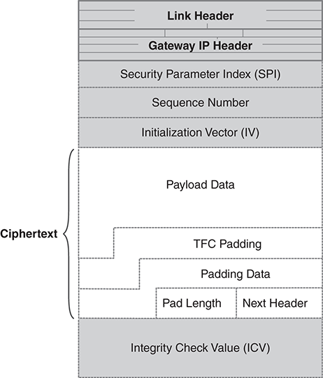
FIGURE 13.24 IPsec ESP packet contents.
Like most packet formats, the ESP puts the control information at the beginning and the integrity check at the end (i.e., the checksum, CRC, or hash value). To allow for block ciphers that require a fixed number of data blocks, there is padding added to the end, too. The end of the packet also includes the “next header” field, which identifies the type of TCP/IP packet encrypted inside the payload data field.
IPsec packets always travel between a pair of hosts that have established a security association (SA) between themselves. This association is similar to an SSL session, except that it is between hosts and not between processes. The SA determines which keys, encryption algorithms, and integrity checking techniques the hosts will use. Each SA is established using IKE.
Here is a brief description of the individual packet fields:
■ Security Parameter Index (SPI)—a numerical value that associates this packet with a particular SA established between the two hosts.
■ Sequence number—each encrypted packet carries a different sequence number, which is used to detect and prevent duplicate packets.
■ Initialization vector—used with many block cipher modes.
■ Payload data—the headers and data being encrypted.
■ Traffic flow confidentiality (TFC) padding—random data appended to the message to improve TFC. This makes traffic analysis more difficult.
■ Padding data—additional padding to ensure the encrypted data fills an integral number of encryption blocks.
■ Pad length—the number of bytes of padding added to fill out a complete encryption block.
■ Next header—the numeric code for the protocol appearing in the first header in the encrypted payload.
■ Integrity check value (ICV)—the result of the keyed hash or MAC calculation used to ensure integrity. The ICV covers all the fields shown here, plus most fields of the packet’s IP header.
Tunnel Mode
In tunnel mode, we encrypt the entire IP packet, including the IP header; then we add an IP header to the encrypted packet and direct that packet to the encrypting gateway that will decrypt it. FIGURE 13.25 shows the resulting packet layout.
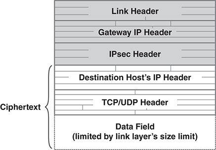
FIGURE 13.25 Packet layout in IPsec tunnel mode.
When an encrypted, tunnel mode packet arrives, the gateway processes it as follows:
■ Discard the plaintext IP header.
■ Decrypt the packet inside.
■ Route the packet to the destination host based on its decrypted IP header.
Because the packet’s actual destination is encrypted, tunnel modes gives some protection against traffic analysis. Attackers still will see traffic between the hosts performing IPsec encryption.
Transport Mode
Transport mode is what we might expect IPsec to do after looking at other encryption protocols: It adds its own header just past the IP header and encrypts everything following its header. Unlike tunnel mode, the process doesn’t duplicate any headers, so it is relatively efficient at transporting data. Most implementations provide integrity protection for the IP header even though it isn’t encrypted itself.
However, transport mode poses a challenge if the site uses network address translation. If we encrypt a packet before it reaches the NAT gateway, the translation will fail. The gateway may be able to correct the IP header, but it won’t be able to correctly modify the encrypted TCP/UDP header. Moreover, the changes to the plaintext IP header will break the packet’s integrity check. To use transport mode with NAT, we must apply the encryption after address translation takes place.
13.4.2 Implementing a VPN
Let us consider an example using a small manufacturing company called Amalgamated Widget. Amalgamated has a company headquarters office, a separate research center, and two factories. Each has its own network. Company headquarters has several corporate information servers. The servers are inaccessible except by Amalgamated employees on the company network. Amalgamated connects the individual networks together using an IPsec VPN.
Private IP Addressing
Because global IP addresses are scarce, many enterprises assign private IP addresses to hosts inside the enterprise network. If the enterprise has several separate sites, these sites need to coordinate their IP address management.
Internally, all Amalgamated IP host addresses are assigned from the “Net 10” private address space. The IT department also has arranged its subnets to make IP routing efficient. Each site has its own set of network addresses. Local hosts receive a “Net 10” address on the local network. Thus, every “Net 10” address is unique across Amalgamated.
IPsec Gateways
The gateway device to every Amalgamated network performs IPsec proxy encryption. When a packet with a local IP address is directed to a different Amalgamated site, the gateway uses tunnel mode encryption to encapsulate the packet; then the gateway addresses the IP packet to the other site’s gateway. Upon arrival, the receiving gateway discards the packet header, decrypts the packet, and delivers it within the local site.
Bundling Security Associations
In a perfect world, we achieve all of our VPN security objectives with a single IPsec SA. In practice, we may face more complicated situations. For example, we may be operating within an enterprise that provides proxy encryption between sites. Thus, our site-to-site enterprise traffic always carries IPsec encryption.
What happens if we use a special third-party product that incorporates IPsec as part of its own, essential security measures? Our traffic will be doubly encrypted as it traverses the internet. This yields a “bundle” of SAs tied to the internet packets.
When IPsec was first introduced, U.S. export controls drove product developers to provide completely separate support for integrity protection and for confidentiality. Typical IPsec packets carried two headers: an AH to protect integrity and an ESP to protect confidentiality. Too, there were bundled SAs to coordinate the cipher suites and keys for each set of headers.
13.4.3 Internet Key Exchange Protocol
The IKE protocol establishes the SAs between a pair of hosts. The protocol identifies the cryptographic algorithms to use and negotiates keys to use. When keys expire on an active SA, the protocol automatically replaces the old keys with new ones. The IKE process begins with a Diffie–Hellman exchange. This establishes a set of shared secrets that then protect subsequent data exchanges (FIGURE 13.26).

FIGURE 13.26 Starting an IKE negotiation.
In this example, Bob is working part-time for a bank and has been given permission to use its VPN connection to work remotely from his laptop. To use the VPN, the laptop first performs an IKE negotiation to establish the SA.
In the first step (shown at the top of Figure 13.26), the laptop assigns a number to its SA, generates a random Diffie–Hellman private key, calculates its public key, and chooses a random nonce. The laptop sends the SA identification number, the D-H public key, and the nonce to the bank’s gateway. The bank’s gateway responds with the corresponding information, calculated on its side. Each host then derives the D-H shared secret and uses it with the nonce to create a key block, similar to the one in Figure 13.19. From this block, both hosts derive secret keys for protecting the remaining data exchanges. The next exchange is protected by one of the shared keys and provides authentication information for the other host to verify. These may be public-key credentials, a shared secret, or credentials calculated from one of these.
Once the hosts have authenticated each other, they have an IKE SA in place. To use IPsec, however, they must negotiate another SA; this one is a “child” SA for use with the IPsec traffic. The negotiation for the child SA establishes the keys to use, the crypto techniques to use, and the other properties of the IPsec association.
The IPsec hosts use IKE to rekey the SAs. The hosts keep key expiration timers. When keys expire, a host may negotiate a new SA to replace the expiring one. At worst, the hosts may repeat the entire IKE transaction, but this isn’t always necessary.