CHAPTER 11
Linear Videotape Editing
The technology of video editing has undergone significant changes in the past several years. Two different technologies are now used for video editing: the traditional linear videotape-based editing systems and the more recently developed digital nonlinear editing systems. This chapter will concentrate on linear videotape editing. Chapter 12 focuses on digital nonlinear systems.
In linear videotape editing systems, videotape is the recording medium. Edits are made in a sequential fashion, one after the other, starting at the beginning of the program or segment and working to the end. The simplest systems are capable of making only one kind of editing transition—a cut.
ELECTRONIC VIDEOTAPE
EDITING SYSTEMS
Electronic editing with videotape is simply a process of rerecording information into a new sequence. Two videotape machines are used: the playback VCR, or source VCR, which contains a videotape with the field footage; and the record VCR, or editing VCR, which contains a blank videotape. Material from the source VCR is recorded onto the editing VCR in the desired sequence. After editing, the new, edited version is on the videotape in the editing VCR, and your original tape remains in its original form on the source VCR. You have made a copy of certain portions of the original, rearranged in a new order.
Although this sounds simple, electronic editing is complicated by the fact that the video signal can be reproduced only when the videotapes are already moving through the machines. Therefore, you need a system that can make an edit at a precise point while both the source VCR and the editing VCR are rolling. In this respect, making an edit can be compared to passing a baton during a relay race. As the runner with the baton approaches the baton-pass area, the runner who will receive the baton begins to run. When the baton actually passes hands, both runners are moving at full speed.
Although linear videotape editing originated in the analog production era, many digital videotape formats can be edited in a linear fashion as well. While linear editing systems have declined in popularity and use since the introduction of nonlinear editing systems, linear systems still find significant use in news and sports production because it is possible to edit directly from the source videotapes without having to take the time to import clips into a computer.
Editing System Components
A complete linear videotape editing system generally includes these components:
1. Playback (source) VCR to play back the original, unedited videotape.
2. Record (editing) VCR capable of performing clean electronic edits on the video signal.
3. Monitors for the source and editing VCRs, to allow the editor to see and hear the audio and video from each source.
4. An edit control unit for controlling both VCRs, so that edit points can be found and edits precisely made by incorporating an adequate preroll time that allows the machines to reach their edit points at the same time. This component is necessary because in videotape-based editing systems, an edit can be made only when the source and edit tapes are rolling at full playback and record speeds.
5. Auxillary audio components, which may include an audio mixer and CD or audiotape recorders to input additional audio sources like sound effects and music.
6. A graphics generator to produce titles, credits, and other program graphics.
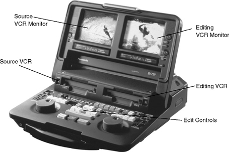
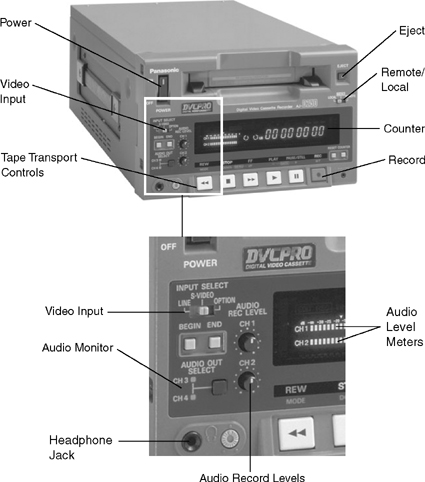
A linear video editing system may be assembled out of free-standing individual components (VCRs, monitors, edit controller, etc.) or, as in the case of Panasonic’s professional DVCPRO editing system, it may be manufactured as one integrated piece of equipment. (See Figure 11.1.)
The Editing Videocassette
Recorder
To edit electronically, a special type of videocassette recorder—the editing VCR—is used. An editing VCR accomplishes an edit by synchronizing the incoming signal from the source VCR with the signal on the editing master tape. The editing master tape is the tape in the editing VCR onto which the program material is being edited. For the edit to be accomplished cleanly, the editing VCR must begin recording a new field (track) of information at precisely the same instant that the source VCR plays back that field of information. In addition, the edit must be made between frames of information on the videotape in the editing VCR.
Edit Control Unit Standard Controls
The process of locating editing points and then backspacing the machines several seconds to allow adequate preroll time—also called backtiming, prerolling, or cuing—is done with an edit control unit that reads control track pulses or SMPTE time code.
VCR Tape Transport Controls. All edit control units contain a set of standard controls. First, the controller contains a set of player (source VCR) and recorder (editing VCR) controls for both of the machines in any of their normal operating modes: play, fast forward, rewind, stop, and so on. Usually, the left side of the edit control unit contains a full set of controls for the source VCR, and the right side contains all the controls for the editing VCR. The edit control unit, then, is simply a remote control device that can be used to control the playback and record functions of the machine (see Figure 11.2).
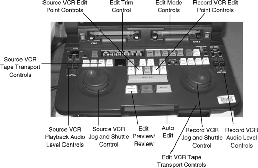
Jog and Shuttle Control. Because editing demands that precise frames of information be found at the edit points, the control units also typically contain a jog or shuttle control that allows the editor to look at the image on either machine in a number of different modes: frame by frame, slow motion, normal motion, and fast motion. Through the use of the jog or shuttle control, the tapes can be jogged forward or in reverse with the videotape against the VCR heads. The picture and sound are displayed in the monitor, allowing the editor to select the precise frame to be edited.
Edit Mode Controls. The center part of the edit control unit contains the editing controls. The edit mode buttons are used to select either the assemble- or insert-edit mode. (These modes are explained later in this chapter.) If the insert mode is selected, an additional group of buttons allows the operator to select video, audio 1, or audio 2 in any combination as the signals to be inserted.
Edit Point Controls. These buttons allow the editor to set in and out points for the edits. Most edit control units use the three-point method of editing: an in and out point are set on the shot in the source VCR, and an in point is set on the editing VCR, designating the destination of the material from the source VCR. There is no need to set an out point on the editing VCR as the edit will end when the source tape gets to its end point.
Trim controls are used to add or subtract frames from an edit point.
The preview control allows the editor to see what the edit will look like, without actually performing the edit.
The auto-edit control automatically prerolls both VCRs the designated amount of time (typically three, five, or seven seconds) and then performs the edit.
Review and Go To Controls. Other controls allow the editor to review the edit or go to the edit in and out points.
After the edit has been made, the control unit will stop both tapes and rewind the editing VCR to the exit point of the edit just completed. When the review control is depressed, the control unit rewinds the editing VCR to a point in front of the entry point of this edit. It then puts the machine into the play mode so the edit can be viewed at normal playing speed. You should always review each edit at normal speed and in slow motion after it has been recorded. Make sure that the edit achieves the desired aesthetic effect, and check it for technical accuracy and stability. The go to control moves the tape in either machine to a specified point—typically the entry or exit point of the previous edit, or in VCRs with SMPTE time code, to a particular time code location in the tape.
CONTROL TRACK AND SMPTE
TIME CODE EDITING
Control Track Editing
Edit control units may use the tape’s control track as a reference for the edit cues, or they may use SMPTE time code. The problem with control track editing is that all control track pulses look the same, and the edit control unit controls the tape by counting the pulses before the edit point to cue the tape and by counting the control track pulses between the edit points to perform the edit. For example, if the edit control unit is set to a five-second preroll, when the command to perform the edit is given, the edit controller prerolls (rewinds) the tape five seconds by counting 150 control track pulses. If there are any missing pulses, the edit point will be inaccurate. Similarly, if the machine doesn’t stop and start precisely—that is, if there is a mechanical error in the rewind and stop functions—the edit point will also be inaccurate.
Editing with SMPTE Time Code
SMPTE time code systems allow for more precise editing because the edit reference point is keyed to a particular time code number. Because of its accuracy, SMPTE time code is widely used in videotape recording and editing. Entry and exit points for each shot can be logged in terms of their time code numbers, and a complete list of all of the shots that will compose the program can be compiled. The editor can then use the jog and shuttle controls to move the source and edit tapes to their appropriate in and out points, or if the edit control unit has a numerical keypad, the time code numbers can be entered into the control unit’s memory and stored until the edits are performed.
Setting the Edit Points
Edit points are set by finding the precise frame on which the edit is to be made and then putting the machine into the pause mode at that point. The precise frame of the edit is found by using the jog or shuttle control with the VCR operating in the search mode. Edit entry and exit points are then entered into the edit control unit by pressing the appropriate buttons to set the entry and exit points for the source and record VCRs.
On some systems, it is possible to enter edit points on the fly, with the VCR in the play mode. When the editor sees the desired edit point (or hears it, if this is an audio edit), the editor pushes the edit entry control as the tape is playing. This enters the edit point into the system. The difficulty with entering the edit decisions on the fly is that accuracy depends on the speed of the editor’s reaction. If the editor’s reflexes are slow, the edit point may be off by a second or more. For this reason, the search mode is most often used to enter edit points by slow-speed searching for the precise frame and then putting the machine into the still-frame mode at the edit point.
Backspacing
Once the edit entry and exit points have been entered into the control unit, the VCRs need to be cued to a point before the edit entry points so that both VCRs can be backspaced. The control of this process—also called backtiming, cuing, or prerolling—is one of the most important functions of the edit control unit.
Perhaps the most common problem encountered with the control track edit units occurs when you attempt to cue a tape that lacks enough control track in advance of the edit point to allow the control unit to back-space the tape. Tapes must always have at least five seconds of continuous video information and control track before the edit point. Just to be safe, it is better to have more than five seconds (10 seconds is good).
Problems with Control Track Editing
Control Track Pulses. The main weakness in control track editing systems lies in the fact that all control track pulses look the same to the edit control unit, which is capable of counting control track pulses only when it cues the VCR. An error in counting will affect the amount of time the VCR is backspaced, thereby affecting the accuracy of the edit.
Accuracy. Control track editors are not frame accurate. That is, they seldom make the edit exactly on the planned frame. Most systems are accurate only within two to four frames on either side of the planned edit point. In many situations, this is good enough, but in some it is not. Two factors contribute to the inaccuracy of these editing systems: problems with counting and system mechanics. Pulse counting tends to be more accurate when edits are of short duration and less accurate when they are long. In a one-second insert, only 30 control track pulses need to be counted to mark the edit entry and exit points. On the other hand, in a one-minute insert, 1,800 pulses are counted and the chances of miscounting are magnified. If the pulses are not counted correctly, the edit points will be off the mark.
The other problem with the accuracy of control track editing systems lies in the mechanics of the machines. When the VCRs cue up a shot, they rewind five seconds and then pause the tape. However, the braking mechanism in the VCR is not always frame accurate. The VCR may overshoot the mark by several frames. However, because all control track pulses look the same, the control track editor will not know that the VCR is several frames off. When the perform edit command is given, it will simply count off 150 pulses—not 152—and will assume that it has reached the edit point correctly. For this reason, the more times you preview or rehearse an edit, the greater the chance of the system making an error when it performs the edit.
Some VCRs are more mechanically accurate than others. New VCRs are usually more accurate than old VCRs, and certainly well-maintained VCRs are better than abused ones. However, no matter how good the condition of your VCR and editing system, you will seldom be able to achieve frame-accurate editing with a control track editing system.
Varying the Preroll Time
Most linear editing systems use a five-second preroll. On some systems, preroll time can be increased or decreased. If your machines stabilize quickly, you may be able to reduce the time to three seconds. By reducing the preroll time, you can edit with less control track at the head of each shot, and you can save a second or so every time you make an edit. On the other hand, if you have a piece of videotape that refuses to stabilize during a 3, 5, or 7 second preroll, you can increase the preroll time to seven seconds to give the tape a few extra seconds to stabilize.
LINEAR VIDEOTAPE EDITING MODES:
ASSEMBLE AND INSERT EDITING
There are two principal linear editing modes: assemble editing and insert editing.
Assemble Mode
Assemble editing replaces all the signals on the edit master tape with new ones (audio, video, and control track) whenever an edit is made. In this mode it is impossible to edit the signals individually. For example, in the assemble mode, you could NOT make a video-only edit, or make an audio-only edit to add music. Whatever is on the source tape will be transferred to the edit master tape.
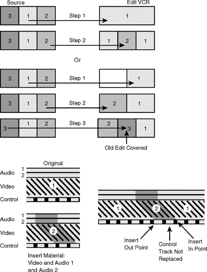
In order to finish a program edited in the assemble mode, all edits must be made in sequential order, starting at the beginning of the program with the first edit, and working toward the end. (See Figure 11.3.) You cannot go back into the program and make a new edit in the assemble mode. if you try to do this, you will create a gap in the tape at the end of the edit, and when you play back your program, the picture will become unstable and there will be a momentary loss of audio and video.
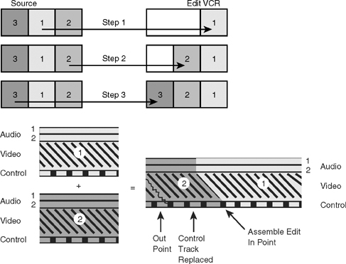
FIGURE 11.3 Assemble Editing
Insert Mode
The other linear videotape editing mode is the insert mode. In the insert mode, audio and video tracks can be edited selectively. They can be edited independently or in combination. For example, you can edit video only, audio 1 only, audio 2 only, or video and audio 1, video and audio 2, video and audio 1 and audio 2, or audio 1 and audio 2.
In addition, an insert edit does NOT erase or record control track on the edit master tape. Since control track is necessary for tapes to play back, insert editing requires that a tape with control track be prepared to edit onto. The typical way to approach this is to take a blank tape and record video black onto it. Video black is a black video signal. In studio production facilities, video black can be sent out of the video switcher to a record VCR, or a black video generator can be connected to a VCR. If neither option is available to you, put a blank tape into your camcorder and close the iris and/or cap the lens. The camcorder will record a black picture.
Unlike assemble editing, insert editing does allow you to go back into an edited sequence and insert new video over an existing shot, or replace the audio tracks with new audio. (See Figure 11.4.) The edit will be stable at the entry and exit points.
However, despite being called an insert edit, this edit mode does not allow you to insert a shot between two other shots. That is, you cannot pull a sequence apart, insert a new shot, and finish with a sequence that is longer than the one you started with. Perhaps it would be more useful to think of an insert edit as overlaying or overwriting new video (or audio) on top of existing audio or video material. (See Figure 11.4.) The old material is erased, and the new material is inserted into its place on the videotape.
Approaching Assemble Editing
To perform an assemble edit, two VCRs are needed: the source VCR containing the original unedited material, and the editing VCR containing the edit master tape (which is the tape onto which the edits will be made). Because assemble editing involves adding information to a tape in sequence, the tape in the editing VCR cannot be blank. It must have video information and control track on it for the edit to be made properly. If you already have some information recorded on the tape in the editing VCR, assemble editing is easily accomplished. You simply add new material to the end of the old material. But what do you do at the beginning of a program? How do you make the first edit of a program onto a blank tape?
To make the first edit in a program, it is customary to record some color bars or video black at the beginning of the edit master tape (see Figure 11.5). This provides a video signal and all the synchronizing pulses that the editing VCR needs to make an edit, because control track pulses are recorded whenever a video signal is recorded on a VCR.
If a video signal and control track are not present on the edit master tape, the first edit will be unstable. The editing VCR needs control track to regulate its playback speed. Also, without video information on the tape, there is no way to synchronize the movement of the video heads so that they begin recording the new tracks of video information at the correct place on the tape.
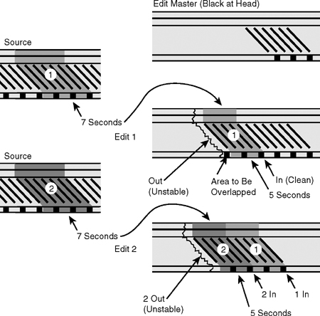
Overlapping Edits
When using assemble edits to construct a program, the technique of overlapping edits is employed. An overlapping edit is one in which the end of the last shot recorded on the editing VCR is erased and recorded over by the beginning of the next shot that is being transferred from the source VCR. This technique covers up the messy picture breakup that always comes at the end of an assemble edit.
Assume that you want to transfer seven seconds of Shot 1 on the source VCR to the editing VCR. If you end the assemble edit precisely at the seven-second mark, the picture will break up, causing a problem in the program. The solution is to record more than the seven seconds you need.
Then begin the next edit at the seven-second mark of Shot 1 and erase the breakup after that point. Figure 11.5 illustrates this technique.
Whenever you are editing in the assemble mode, use this technique of overlapping edits. Always allow both the source and editing VCRs to roll several seconds beyond the planned end point of the edit, and then record the beginning of the next shot over this material (see Figure 11.5).
Problems with Assemble Editing
Each time an edit is made in the assemble mode, a new segment of control track is recorded. If the edit is not made in precisely the correct place, or if there are any irregularities in the signal on the source VCR (which is now being recorded onto the editing VCR), this will cause a momentary loss of stability in the final edited program. For this reason, most professional editing is done in the insert mode, even if the editor is simply recording the shots in sequence. Using the insert mode guarantees a continuous, uninterrupted control track on the edited master tape because control track information is never affected in the insert editing mode.
Assemble-Editing Review
Let’s briefly review what we know about assemble editing. An assemble edit involves the transfer of information from the source VCR to the editing VCR. Shots or sequences are added onto the tape in the editing VCR in the desired sequence. From a technical standpoint, assemble editing means that each time an edit is made, the editing VCR records new video, audio (both channels if on a two-channel VCR), and control track. Furthermore, an assemble edit is used for editing in only—that is, it adds new information to the end of other video information already present on the tape in the editing VCR. The beginning of the edit is stable, but the end of the shot will break up where the edit ends because control track and video information will be missing from the tape in the small space between the location of the stationary full-track erase head and the place where the video record heads hit the tape.
Approaching Insert Editing
To edit in the insert mode, the tape you are editing onto must have continuous prerecorded control track and video information for the entire length of the edited program. As explained, the control track is needed because new control track information is not recorded in the insert mode. Therefore, the master tape must have control track on it to regulate the tracking of the editing VCR. In addition, the control track must be continuous. If there are any breaks or interruptions in the control track, the edits will not be stable. The picture will break up wherever control track pulses are missing.
Therefore, before you can begin editing in the insert mode, you need to know the length of the finished program. You then need to record enough control track onto the edit master tape to safely cover the length of that program. For example, before you can begin editing a 10-minute program segment, you need to record at least 10 minutes of video black and control track onto the tape. It is always a good idea to lay down more control track and black than you think you will need. Then, if you slightly exceed the projected program length, you will still have some control track and video black to work with. To protect against running out of control track, most professional editors simply lay control track down along the entire length of the tape they are editing onto.
Video Black
Video black is simply a color-black video signal recorded onto a videotape—usually for the entire length of the tape—when the tape will be used as an edit master tape. This color-black video signal includes color burst, the pulse that controls the phasing of the color signal and activates the color circuitry in a television receiver, as well as the horizontal and vertical sync pulses associated with the video signal. When video black is recorded onto a tape, control track is automatically recorded as well, because the control track is triggered by the vertical sync pulses in the black video signal.
At this point, it is important to note that having video black is different from having no video signal. A videotape with video black recorded onto it is not a blank tape. A blank tape contains no video signal, whereas video black is indeed a video signal. If you look at video black on a monitor, you will see a stable black screen. If you look at the signal on a waveform monitor, you will see that it does indeed produce a video waveform, and you will be able to identify the sync pulses and color burst in the waveform.
Blank tape, on the other hand, has nothing recorded on it. There is no video signal, sync, or color burst. When you play back a blank tape and look at it on a monitor, you will see snow, or the screen will be black but the picture will jitter and roll. On some systems, the screen will be blue. If you look at a waveform monitor, you will not see the characteristic video waveform because no signals are recorded on the tape.
Video black is used in the editing VCR because it provides a stable reference signal into which your new video and audio information can be laid. Because control track pulses are recorded as the black video signal is laid down, the editing VCR will have the information it needs to maintain stability throughout the program.
Some videotape editors prefer to lay down color bars instead of video black for the entire length of the tape. The reason for this is that occasionally, when editing, you may accidentally leave a small bit of space between the end of one edit and the beginning of the next. In the insert mode, the end of the edit is as clean as the beginning of an edit, and these mistakes are sometimes hard to see. If you are editing onto a tape with video black recorded onto it, you may not see the space between the shots when you play back the tape. But, if you are editing onto a tape with color bars on it, the space between shots will reveal an unerased segment of color bars that will jump out at you like a red flag at a bull in a bullring. You can then correct this error by redoing the edit to eliminate the gap between the shots.
Assembling in the Insert Mode
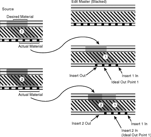
Although insert editing is most commonly thought of as the process of inserting new information into a prerecorded shot or sequence, it is also possible to assemble a program in the insert mode.
You may wonder why anyone would want to do this instead of simply using the assemble-editing mode. The answer, of course, lies in what has already been said with respect to the control track. In the assemble mode (technical process), the old control track is erased and new control track recorded with each edit. The problem with this process is that you have a good chance of winding up with a slightly irregular control track. Even slightly inaccurate timing of any edits or inaccurate spacing of the edit master control track pulses results in an unstable edit that may cause the picture to break up or roll. In a program with several hundred edits, the chances are good that at least one control track segment will be bad.
In the insert mode, however, the control track is not affected during the editing process. Therefore, assembling the program in the insert mode usually produces a higher-quality finished product. As in assemble editing, the process of overlapping edits is usually followed. While this is not necessary from a technical standpoint, because the output of the edit will be clean and stable, overlapping edits are used because most editing systems are not frame accurate. Recording more information than you need as you lay down each shot on the edit master is a safety measure that prevents a black space from appearing in the tape between shots, even if the next edit is a frame or two late (see Figure 11.6).
Insert-Editing Review
Insert editing differs principally from assemble editing in that the edit master tape—the tape onto which you will edit—must already have a continuous control track. In the insert mode, the control track is not erased because unlike in the assemble mode, the VCR’s large stationary erase head is not activated. Rather, the insert mode uses the small flying erase heads, which are positioned immediately in front of the video record/playback heads. These flying erase heads erase only the tracks of video information that have previously been laid down on the tape. They do not affect the control track at all and may be used in conjunction with or independent of the stationary audio erase heads. The result is that in the insert mode, you can insert new video, linear channel 1 audio, linear channel 2 audio, or any combination of the three. You can do video-only edits, in which new video information is laid down and the linear audio channels are left undisturbed. Or you can do audio-only edits, in which the old video information is left undisturbed. In addition, you can combine video and audio insert edits. For example, you can insert new video and linear channel 1 audio onto the master tape, leaving linear audio channel 2 undisturbed. Or you can insert new video and linear channel 2 audio, leaving channel 1. Insert editing gives the editor maximum flexibility during the editing process.
Interformat Editing
For years, it was standard practice to edit videotape onto the same tape format on which it was originally shot. However, given the proliferation of videotape formats and the advantages of some formats as field acquisition formats and others as editing formats, this is no longer always the case.
Because editing is an electronic process in which the signal from a source machine is rerecorded onto the editing VCR, tapes that were recorded in the field in one format can be edited to master tapes in another format. This is known as interformat editing.
Tapes that have been shot in the field in one format can, of course, first be dubbed to another format for editing if the editing system format is different from the field-recording format. However, you lose a full tape generation in the process. Interformat editing eliminates the intermediate dubbing step and thereby saves one generation, as well as the time it would take to dub the tapes.
The increase in the popularity of digital nonlinear editing systems has reduced the need for interformat editing, as field material may be recorded on any tape format and then imported into a digital nonlinear system. When the editing process is complete, the finished program can be output back to the tape format on which it was originally recorded, or it can be recorded onto a different format for viewing and distribution.
Linear Videotape Editing Process
The process of editing a program with a linear videotape editing system generally follows these steps:
1.Shoot footage in the field or in the studio. Record SMPTE time code as the footage is being shot.
2.Make a window dub of your source tapes.
3.Log the tapes.
4.Develop a preliminary edit decision list (EDL)—a list of all the shots you plan to use in your production with in and out points and a brief description of each shot.
5.Make a rough cut of the program. This is a preliminary version of the program.
6.Review the rough cut and adjust your editing plan as necessary. If your production is being produced for a client, you will want the client to review the rough cut to give you feedback before you produce the final version of the program.
7.Complete the final edit, adding graphics and music to produce a compelling audiovisual program.
EDITING ON A
CUTS-ONLY SYSTEM
Cuts-only editing systems are very basic, consisting of two VCRs (source and editing), two monitors (one for each VCR), and an edit control unit. These simple systems are referred to as cuts-only editing systems because the only transition they allow the videotape editor to use is the cut. Dissolves, wipes, and other special effects require at least two source VCRs and a video switcher interface (this is called an A/B roll editing system) or a digital nonlinear editing system. A/B roll editing systems have been made obsolete by nonlinear systems, which perform complex editing operations more easily and more cost-effectively.
Videotapes
You will need at least two videotapes to edit. One or more tapes will contain the original unedited material. These tapes will go into the source VCR as they are needed. You will also need one blank tape, which will become the edit master tape and will go into the editing VCR. If you plan to edit in the insert mode, this tape should contain video black and control track for the expected length of the program. If you plan to edit in the assemble mode, you will need some video black or color bars and control track at the beginning of the tape so that the edit control unit can cue up for the first edit.
Source VCR Setup
Once the basic editing system is in place and you are ready to begin editing, you need to prepare the source and editing VCRs. (See Figure 11.7.) First, turn on the power to all elements of the system and insert your original tape into the source VCR. Before you can begin to edit, several switches and meters need to be set in the proper position on the VCR.
Remote Control. In systems where the edit control unit and VCRs are separate components, to control the VCR from the edit control unit, place this switch in the remote position. When it is in the local position, the VCR is controlled by the tape transport controls on the front of the VCR. In integrated systems like the one shown in Figure 11.1, the edit control unit is set to local to control the built-in VCRs.
Audio Monitor. In the mix position, channels 1 and 2 will be heard on the playback monitor. For selective track monitoring, set to either channel 1 or channel 2.
Video Input Signal Selector. Set the video input signal selector for the input going into the VCR. The line position is used to record video signals from normal composite video sources, the Y/C 358 or S-Video position is used for S-Video inputs, and the Y, R-Y, B-Y position (Y, Pb, Pr on digital VCRs) is for component video inputs. If the source VCR is a play-only machine, it will not have an input signal selector, because it is not capable of recording an input signal.
Sync. The sync switch tells the VCR what the source of vertical sync is for this machine. In most situations, you should set the sync switch on the playback VCR to the internal position. This means the VCR will be synchronized to an internal crystal oscillator with a frequency of 60 cycles per second. In large editing facilities, the source VCR may be operated in conjunction with house sync (sync supplied by an external sync generator to all the video equipment in a given facility) or a time base corrector (TBC), an electronic device that improves the stability of the playback signal. In both of these situations, set the sync selector switch to the external position.
Tracking. If you are using analog VCRs, you will need to adjust the tracking. (Digital VCRs adjust tracking automatically.) Once you have selected the correct sync position, put the VCR into the play mode. When the image appears on the monitor and stabilizes, adjust the tracking control so that the needle reaches the maximum position on the tracking meter. If all of your tape was shot on the same VCR, you will not have to adjust tracking again. However, if you are using tapes that were recorded on a number of different machines, or if you notice the tracking meter wavering from the maximum position, you will have to readjust the tracking control. Some source VCRs have a tracking control but no tracking meter. In that case, adjust the tracking control until the picture in the monitor is clear and stable.
Counter. Select the appropriate tape counter: TC for SMPTE time code, CTL for control track.
Editing VCR Setup
Once the source VCR is set, you can turn your attention to the editing VCR.
Remote Control. Set the switch to the remote position to control the VCR through the edit control unit on systems where the VCR and edit controller are separate components, or to local on systems where VCRs and edit controllers are manufactured as integrated components of the editing system.
Audio Monitor. Select mix (or channel 1 or 2). In addition, on digital VCRs you may have to select between analog and digital audio inputs.
Video Input Signal Selector. This switch should be set either to the line position, the S-Video or Y/C 358 position, or the Y, R-Y, B-Y position, depending on the source recording.
Sync. Set the sync selector switch on the editing VCR to the normal position, unless you have an external sync input from a house sync generator or a time base corrector. The normal setting allows the editing VCR to reference to incoming sync from the source VCR, thus making editing possible.
Tracking. On analog VCRs the tracking level should be set with the tape in the play mode, just as tracking was set on the source VCR. On digital VCRs there is no manual tracking control. If you are editing in the insert mode or the assemble mode and have video black recorded on the entire tape (insert mode) or just on the head of the tape (assemble mode), you will need to set your tracking level only once. No adjustment should be made after this initial adjustment.
Counter. Once you have set the sync, tracking, and input controls, stop and rewind the tape. Then select the counter, as you did on the source VCR.
Record Levels. It is now time to set the record levels on the editing VCR. Video and audio levels can be set independently. Most machines allow you to set the levels on automatic gain control (AGC) or to adjust them manually. Most editors prefer to set the video level on AGC because video levels on field tapes tend not to vary greatly since much of the initial level control during recording is automated by the camera and the VCR. In contrast, because audio levels in field recording may vary greatly, it is typical to adjust the audio level manually.
Most audio and video meters on editing VCRs show audio and video levels when the machines are in the electronics-to-electronics, or E-to-E, mode. Some machines go into this mode if the VCR is in the stop mode; others go into this mode if the record button is pressed while the machine is in the stop mode. In the E-to-E mode, the record circuits are engaged, and the output of the source VCR is looped through the editing VCR. This allows you to see the incoming audio and video levels on the editing VCR’s meters and to see and hear picture and sound on both the playback and record monitors.
Once the levels are set, press the stop button on the editing VCR to break the E-to-E loop. Then press stop and rewind on the source VCR. You are now almost ready to edit.
Editing Leader
One last thing requires attention before you begin editing. Every edited master tape should have a standard leader sequence at the head of the tape before the beginning of the program. This standard leader serves a number of purposes. First, it provides protection for the beginning of the program. Remember, the first part of the videotape is the part grabbed by the mechanical arm in the VCR and wrapped around the head drum. This part of the tape is therefore subjected to considerable stress, and is occasionally damaged. Try to avoid using the first minute or so of tape for critical information—such as the beginning of your program! By placing identifying leader at the head of the tape, the beginning of your program will be protected from the machine’s mechanical maw.
The other reasons for using a standard leader are to identify the program on the tape and to give your engineering staff a way of checking the audio and video signal levels before the program starts. Finally, the leader provides a way to cue up a tape so that the beginning of a program can easily be found. There is nothing more frustrating than watching someone try to find a 30-second program that was recorded somewhere on a 120-minute tape without any identifying leader before it.
Unfortunately, there is no standard videotape leader. Commercial editors, independent editors, broadcasters, and corporate editors all use somewhat different leaders. However, the following leader sequence is extremely useful:
| Video black | 10 seconds |
| Color bars with tone (0 dB) | 60 seconds |
| Slate (program identification) | 10 seconds |
| Countdown leader | 8 seconds |
| Black | 2 seconds |
| Program start |
This leader sequence provides all the necessary advantages. It provides a 90-second buffer between the beginning of the videotape and the beginning of the program; it gives the engineering staff video and audio reference levels; and its countdown allows the tape to be accurately cued up for playback. No edited tape should be produced without this or another similar leader.
You can assemble your own leader by editing together the material you need in the proper sequence. Use the camera to record video black if you do not have a switcher with a video black output available. Color bar and tone generators are common fixtures in all studios and postproduction facilities. If you do not have access to them, you can improvise. Many cameras now have a color bar output, and some audio mixers have a tone oscillator. You can combine the two to create color bars with tone. You can make your own slate and record it, and if you do not have a prerecorded countdown leader, you can easily make one by editing together one-second segments of the numbers 10, 9, 8, 7, 6, 5, 4, and 3. Leave two seconds of black at the end of the countdown before the program begins.
Editing Strategy
Setting Edit Entry Points. Try to set the edit entry points as accurately as possible. If you are editing to audio, try not to cut off the first part of the first word spoken by your subject. Sometimes, it is better to start with a brief pause than to risk cutting off someone in the middle of a word.
Setting Edit Exit Points. If you are editing in the assemble mode (or if you are assembling a program in the insert mode), use the technique of overlapping edits. Let the edit continue past your planned exit point, and then cut off this unwanted material when you set the entry point for the next edit. This gives you a little breathing room for the next edit. It is better to have a little room after the shot than to cut it so closely that you have to cut the tail off the shot on the edit master tape when you make the next edit.
Avoiding Overuse of the Pause Mode. It is a good idea not to leave either VCR in the cue/pause or preroll mode for any significant time while you are looking for the edit points on the tape in the other VCR. When a VCR is in the pause mode, the heads continue to hit the tape. This is what produces the still-frame image on the monitor. Excessive use of the pause mode may wear out the tape in that spot. The oxides may wear off the tape, causing the image to look bad or even causing the video heads to clog. Some machines automatically go into the stop mode if they are left in the pause mode for more than a few minutes.
An easy way to avoid leaving a tape in the pause mode for too long is to set the edit points on the source VCR before you set the edit points on the editing VCR. It usually takes longer to find the edit points on the source VCR because you may have a number of takes of each shot or perhaps a number of tapes from which to draw your material. On the editing VCR, however, the next edit is almost always made immediately after the last one on the tape, so it does not take very long to find the entry point.
Performing an Assemble edit
Once the VCRs are set up, the tapes are tracked to a maximum, and your record levels are set on the editing VCR, you are ready to begin editing. To do this, you must follow these steps:
1.Select the assemble-editing mode on the edit control unit.
2.Find the edit entry and exit points on the source VCR, and enter them into the edit control unit.
3.Find the edit entry point on the editing VCR, and enter this into the edit control unit.
4.Preview the edit. Watch the editing VCR’s monitor to see if the edit takes place at the correct spot. Also, listen closely to the audio. Does it sound correct? Is the level correct? If the preview is satisfactory, continue to step 5. If the preview is not satisfactory, reset the edit point that is causing the problem.
5.Perform the edit.
6.Review the edit.
7.If the edit is satisfactory, continue on to the next edit. If it is not satisfactory, redo the edit.
Performing an Insert edit
The following steps detail how to perform an insert edit:
1.Select the insert-editing mode on the edit control unit, and select the type of insert you want to make (video, audio 1, or audio 2).
2.Locate the critical out point of the edit. Is it on the tape in the source VCR? Or is it on the tape in the editing VCR? Enter the edit entry and exit points for the critical tape. Enter the edit entry point on the other tape.
3.Preview the edit.
4.Perform the edit.
5.Review the edit.
6.If the edit is satisfactory, continue on to the next edit. If it is not satisfactory, redo the edit.
Manipulating Audio
If all you want to do is transfer material from the source VCR to the editing VCR, then the simple editing system and procedures already described will suffice. However, most editors want to do a little more with their material in the editing process. Most frequently, they also want to manipulate the audio.
Audio Patch Bay. Every simple editing system should contain at least a simple audio patch bay or switch that allows the editor to manipulate the audio as it flows from the source VCR to the editing VCR. A simple device that allows you to send the source VCR’s channel 1 to either channel 1 or 2 on the editing VCR and the source VCR’s channel 2 to either channel 1 or 2 on the editing VCR is essential. Although it is possible to reach behind the VCRs and simply repatch the audio inputs when you need to redirect the audio signals, an outboard patch panel can save a lot of wear and tear on the VCR’s cables and connectors (see Figures 11.8 and 11.9).
Multiple Audio Sources. The next step up in complexity with respect to audio manipulation is having the ability to incorporate additional audio sources into your edited program. You will often need to add narration, music, and/or sound effects to the edited program. How can you do this? One way is to patch the additional audio sources directly into the editing VCR. Most machines have inputs for microphones or line-level inputs for CD players and audio recorders. However, with direct patching into the editing VCR, it is very difficult to lay down the information accurately at the edit point. If you do not manually activate the record circuits and cue the audio to roll at the right time, you are out of luck.
A much better way to deal with the problem is to record the audio information that needs to be dubbed into the program onto another videocassette. New or additional audio information can easily be integrated into a program if it can be controlled and cued in the same way that videocassettes can be controlled and cued. For this reason, it is a good idea to keep several videocassettes on hand with video black and control track. If you need to add music to a program and you have it on audiotape, transfer it first to the appropriate audio channel of one of the videocassettes with the video black and control track. With the audio information recorded onto a videotape, it can now be cued by using the edit control unit.
New audio information can be added to the edit master tape by doing an audio-only insert into the appropriate linear audio channel on the editing VCR. Voice-overs can be added in the same way. Record the voice-over onto a videocassette that has been blacked, and then insert this cassette into the source VCR. All cuing can then be done with the edit control unit.
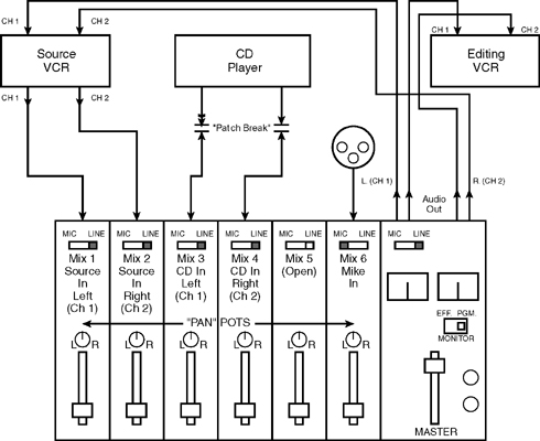
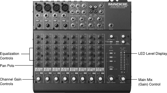
If multiple audio sources are going to be used during editing, an audio mixer should be incorporated into the editing system. The audio mixer can be placed into the audio line between the source and editing VCRs. Additional audio inputs can be patched into the system through the mixer. (See Figure 11.9.) The audio mixer allows for precise control of the level of each source sound. In addition, the mixer may incorporate equalization controls to adjust the tonal quality of the source sounds. And finally, many mixers contain pan pots, which can be used to send the source sounds either to channel 1 or channel 2 on the editing VCR, or to both channels simultaneously.
Monitoring Audio While Editing
One aspect of audio that is frequently overlooked in the editing process is the quality of the audio speakers used to monitor the program audio. Many editing systems contain only the audio speakers in the video monitors for the source and record decks. These speakers are usually of very poor quality, and more often than not they mask the way the audio recording actually sounds.
For this reason, you should use a pair of good-quality audio speakers (one for each channel) to monitor the audio while editing. Bookshelf-sized loudspeakers do the job well, as do some of the high-quality minispeakers that have become available in the last few years. These should be used in conjunction with the normal television monitor audio speakers. The high-quality speakers let you hear things that may not be apparent on the television monitor speaker, whereas the television monitor speaker lets you hear the audio the way it will most likely be heard when the program is received at home and viewed on a conventional television.
If you are editing in a very noisy area, use headphones to monitor audio. This way you can hear the program audio without distraction from outside noise.