CHAPTER 3
Video Basics
The Electronic Image
and the Video Signal
At the center of all video field production systems is the portable video camera. A marvel of modern electronics, the video camera produces the electronic video signal.
Whether configured as a stand-alone camera with no built-in recording capability or as the camera section of a camcorder, all video cameras have a number of standard components, including an image sensor, viewfinder, camera control unit, and lens assembly (see Figure 3.1). This chapter will focus on portable video cameras and on the way the electronic image is generated and displayed. Lenses will be discussed in Chapter 6.
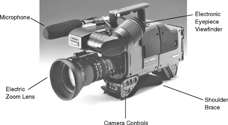
FIGURE 3.1 Parts of a Portable Video Camera
ELECTRONIC IMAGE
REPRODUCTION
The Camera Image Sensor
The most important component of the video camera is its image sensor. Its function is to change light into electrical energy. Technically speaking, the camera image sensor is an optical-video transducer, which simply means that it changes incoming light (physical input) into an electrical video signal (electrical output). By way of comparison, microphones are also transducers—they change incoming sound waves (physical input) into an electrical audio signal (electrical output). Professional video cameras manufactured today use three charge-coupled devices or complementary metal oxide semiconductors as image sensors.
CCD (Charge-Coupled Device) Principles
First demonstrated by Bell Laboratories in 1969, a charge-coupled device (CCD) image sensor is a solid-state semiconductor that converts incoming light into a video signal. Increasingly, complementary metal oxide semiconductors, or CMOS chips, are used as camera imaging devices as well. (See Figures 3.2 and 3.3.) The surface of the CCD or CMOS contains a grid of pixels, or picture elements, arranged in a precise series of horizontal rows, or lines, and vertical columns. The camera lens focuses the scene before it on this array of pixels, each of which is responsible for reproducing one tiny part of the picture. Each pixel contains a metal oxide or silicon semiconductor that converts the incoming light into an electrical charge. The strength of the electrical charge is proportional to the brightness of the light hitting the pixel and the amount of exposure time.
After the incoming light is converted into an electrical charge, it is transferred and stored in another layer of the chip, and then the information is read out one pixel at a time in a line-by-line sequence in conformity with normal television scanning rates. An analogy frequently used to describe this process is that it is like an old-fashioned bucket brigade, except that instead of containing water, each of the buckets—or in this case, each of the pixels—contains an electrical charge.
The CCDs and CMOS chips designed for use in video cameras today are very small (the image-sensing area is 1/6″,¼″, ⅓″ ½″ or ⅔″ measured diagonally) and very rugged, and they consume very little electrical energy.
Electronic Shutter
All video cameras are equipped with an electronic shutter. The electronic shutter controls the amount of time that the incoming light hits the photosensitive layer of the chip. In recording situations in which the recorded image tends to flicker or become blurred because of high-speed movement of the subject in front of the camera, shutter speed can be increased to reduce these picture artifacts and improve the sharpness of the image.

Shutter speeds commonly range from 1/60 to 1/10,000 of a second, with incremental settings of 1/100, 1/250, 1/1,000, 1/2,000, 1/4,000, and 1/8,000, even on some of the least expensive consumer camcorders. In addition, some cameras feature a variable shutter speed that can be adjusted to eliminate the screen flicker that becomes visible when a computer screen or video monitor appears in a video shot.
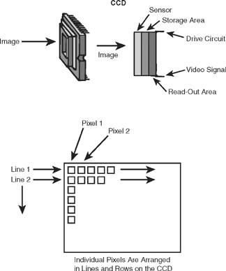
FIGURE 3.3 CCD Image Sensor
Video Display
Your home television set works in much the same way as the camera image sensor, except it reverses the process. That is, instead of turning light into electrical energy as the CCD does, your receiver turns electrical energy into light.
HOW THE VIDEO CAMERA
MAKES A PICTURE—ANALOG
AND DIGITAL STANDARDS
The process of transducing light energy into electrical energy is accomplished by the camera’s imaging device—CCD or CMOS chips—as we discussed. In order to produce a video signal that can be displayed on any video monitor, cameras and video recorders must adhere to a set of technical standards that govern how the video signal is created and displayed. Currently, two sets of standards are in use in the United States: the original NTSC (National Television System Committee) standards adopted for analog television by the Federal Communications Commission in 1941, and the ATSC (Advanced Television System Committee) standards for digital television adopted by the FCC in December of 1996. These standards cover a wide range of technical specifications for how the video signal is constructed and transmitted. For the purpose of this discussion, the important elements of the standards that we will focus on include the aspect ratio of the image, frame and line rates, and scanning patterns.
NTSC Video—The Analog Standard
The NTSC video standards were developed in the United States in the 1930s and have been in use since over-the-air broadcast television was initiated in the United States in the early 1940s. Anyone reading this book who grew up in the United States has been watching television that was based on the NTSC standard.
Analog Signal. In the NTSC system, the video signal is an analog signal. In cameras, an analog signal is one in which the recorded signal varies continuously in proportion to the light that produced it. The video signal can be viewed on a piece of monitoring equipment called a waveform monitor. The waveform produced by an analog video camera corresponds to the bright and dark areas of the scene the camera is recording. (See Figure 3.4.)

Aspect Ratio. The most noticeable feature of the NTSC standard is the shape of the video screen, also known as its aspect ratio. In NTSC video, the screen shape is a standard ratio of 4:3 (width:height). No matter how large or small the screen is, it will retain these standard rectangular proportions in which the screen is only slighter wider than it is tall. (See Figure 3.5.)

FIGURE 3.5 Conventional Screen and Wide-Screen Shapes
Frame and Line Rates. The video image is composed of a number of frames and lines that play out at a specified rate. In the NTSC system, cameras produce 30 frames of video information per second, and each one of those frames is composed of 525 lines of information. Further, each of the individual scanning lines is composed of a series of approximately 700 light-sensitive pixels, or picture elements.
In reality, the precise frame rate for NTSC video has been 29.97 frames per second since the color television standards were developed in the early 1950s. And, of the 525 actual lines, only 480 are actively used to transmit picture information. However, this text follows the widely adopted convention of referring to the NTSC standard as 30 frames per second and 525 lines per frame.
Interlaced Scanning. In the NTSC system, each television frame is constructed through a process called interlaced scanning. When the video signal is output through the CCD, instead of sending out lines 1 to 525 sequentially, each frame is broken up into two fields: one is composed of the odd-numbered lines; the other of the even-numbered lines. First the odd-numbered lines are read out, and then the even-numbered lines follow. At the receiver, the image is constructed field-by-field, and line-byline. (See Figure 3.6.) NTSC video runs at 60 fields per second (actually, 59.94) as there are two fields per frame (29.97 frames per second × 2 fields per frame = 59.94 fields per second).
This somewhat complex system was developed to overcome the technical limitations of early television display and transmission systems. Monitors of the time used CRTs coated with phosphorescent material that would glow when they were scanned with an electron beam.
Unfortunately, if the 525 scanning lines that composed the picture were scanned sequentially from top to bottom, the top of the screen would fade out before the picture was complete. This created a flickering effect in the image. By splitting the frame into two fields and scanning the image one field at a time and interlacing the lines, the problem of flickering was solved and the picture maintained its brightness throughout the program.
The interlaced scanning system also solved a signal transmission problem. A signal transmitted at the rate of 60 fields of 262.5 lines per field could be accommodated within the 6MHz bandwidth assigned to each television station to transmit its signal. A signal transmitted at 60 frames per second with 525 lines per frame contained twice as much information as the interlaced signal but exceeded the capacity of the channel to transmit it. By interlacing the fields, this problem was solved.
Of course, one of the consequences of interlaced scanning is reduced picture quality. Since only half of the lines of each frame are displayed at one time, the picture resolution is significantly poorer than it would be if all of the lines were displayed at once.

Incidentally, the 525-lines-per-frame standard characteristic of NTSC television in the United States is an arbitrary standard. That is, the system could have more or fewer lines and still function. Indeed, many other countries use 625-line systems, which actually provide greater picture detail than 525 lines (see Table 3.1).
| Country | Frames per Second | Lines per Frame |
| United States, Canada, Japan, Latin America | 30 | 525 |
| Europe (most systems), China, Commonwealth of Independent States | 25 | 625 |
ATSC Video—The Digital Standard
Because of the limitations inherent in the picture and color quality of NTSC television, and because of a desire to move from an analog system of broadcasting to a digital system, over the past decade a considerable amount of effort has been invested in developing a new U.S. television standard, culminating in the adoption of the ATSC standards in 1996. Initially, the goal was to develop a set of standards for high-definition television (HDTV), based on a 16:9 aspect ratio (see Figure 3.5) and an increased line rate, to improve picture quality. However, as the standards debate dragged on, great advances were being made in digital recording and transmission technologies.
Finally, at the insistence of the FCC, a “Grand Alliance” of major U.S. electronic manufacturing companies were encouraged to work together to develop a set of digital standards for advanced television services in the United States. The standards that were finally adopted by the FCC allow digital television to be produced and distributed in a variety of scanning formats (see Table 3.2). To receive these signals, consumers will need to buy new digital television receivers or set-top boxes that will convert the incoming digital signal into an analog signal for display on conventional television receivers.
The new standards contain several variants of HDTV, but all include pictures in a 16:9 aspect ratio with more scanning lines and pixels per line than conventional NTSC standards.
ATSC differs from NTSC in many significant ways. One of the most significant differences is that unlike NTSC, in which aspect ratio, frame rate, and line rate all meet a single standard, ATSC is an open standard that is able to accommodate signals with various line and frame rates, and two different aspect ratios. (See Table 3.1.)
Digital Signal. In the ATSC system, the video signal is digital. In digital camera systems, light hits the CCD and creates an electrical charge. That electrical charge is then sampled and converted into a binary digital numerical code consisting of bits made up of a pair of off/on (0/1) pulses. This is called quantizing. (See Chapters 5 and 8 for a more detailed discussion of digital video and audio.)
| Vertical Lines | Horizontal Pixels | Aspect Ratio | Picture Rate | HDTV/SDTV |
| 1,080 | 1,920 | 16:9 | 60I 30P 24P | HDTV |
| 720 | 1,280 | 16:9 | 60P 30P 24P | HDTV |
| 480 | 704 | 16:9 and 4:3 | 60I 60P 30P 24P | SDTV |
| 480 | 640 | 4:3 | 60I 60P 30P 24P | SDTV |
In the “Picture Rate” Column, “I” Means Interlaced Scan and “P” Means Progressive Scan.
HDTV = High-Definition Television
SDTV = Standard-Definition Television
Source: Advanced Television System Committee
In comparison to an analog signal, which varies continuously in relation to the phenomenon that produced it (e.g., variations in the amount of light hitting the CCD), in a digital system only selected points are sampled. As you may imagine, the higher the sampling rate and the more bits assigned to each sampling point, the more accurate the digital code will be.
Aspect Ratio. Early on in the discussions that led to the development of the ATSC standard, one of the goals was to develop a new set of standards for High-Definition Television (HDTV)—television with an increased line rate that could deliver substantially improved picture quality. Another issue that the standards makers had to confront was the fact that all of the present-day feature films are produced in a variety of wide screen formats. Fitting those films onto a television screen means cutting off parts of the picture so that it fits onto the 4:3 frame. ATSC settled on a 16:9 aspect ratio for HDTV to better accommodate the transmission of feature films. In addition, because so much program material had already been developed in the standard 4:3 aspect ratio, the ATSC standard can accommodate that as well.
Frame and Line Rates. Just as the ATSC standard can accommodate various aspect ratios, so can it transmit pictures with various numbers of lines. In addition to the 480-(active)-line-by-704-pixel standard used by NTSC (now called Standard-Definition Television or SDTV), the ATSC standard contains two HDTV standards with either 1,080 lines and 1,920 pixels/line or 720 lines and 1,280 pixels/line, as well as the 480-line-by-640-pixel variant that is equivalent to the super VGA standard used to display graphics on computer screens.
The ATSC standard includes the 60-field-per-second (30-frame-per-second) interlaced scanning standard that NTSC is based on, and also can accommodate signals based on a 24- or 25-frames-per-second standard. Twenty-four frames per second is the standard projection rate for feature films. Twenty-five frames per second is the standard used by European broadcasters, and in other countries throughout the world that are not based on NTSC.
Progressive and Interlaced Scanning. Improvements in video displays have eliminated the technical issues that required interlaced scanning. If you have ever sat in front of a computer monitor, you have viewed an image in which each of the lines is scanned progressively. In progressive scanning each of the lines in the frame is scanned successively. In the 720-line system, scanning begins with line 1 and continues to line 720; then the process repeats. (See Figure 3.6.)
The ATSC standard accommodates progressive scanning as well as interlaced scanning. For example, one of the popular HDTV formats uses 720 scanning lines, scanned progressively. Yet another popular HDTV format relies on 1,080 scanning lines, interlaced.
Production equipment has been produced to accommodate some of these standards and more is in development. Many of the new cameras available to professional video producers have selectable frame rates and aspect ratios, allowing the cameras to be used to provide program material in a variety of the digital formats. Even many inexpensive camcorders allow for aspect ratio changes from 4:3 to 16:9, and some are capable of 24 fps progressive scanning as well. The 24 fps frame rate is popular with videographers who want to achieve a “film look” in the material they shoot.
In addition to high-end professional HDTV cameras and camcorders, several manufacturers have introduced inexpensive HDTV camcorders based on the DV tape format. (This is discussed in more detail in Chapter 5.) These HDV camcorders range in price from approximately $2,000 for a single-chip consumer camcorder, to $6,000 to $10,000 for a three-chip model.
VIDEO SIGNAL
CONTROL
Horizontal and Vertical Sync
Regardless of whether the video signal is produced within the NTSC or ATSC standards, each frame of video information is constructed by combining picture information and synchronizing information. Among the most important synchronizing control pulses are horizontal and vertical sync and blanking pulses. These pulses are generated by a sync generator that can be located as an integral component inside the camera or as a separate component outside the camera.
The horizontal sync and blanking pulses control the timing of each line of video information; the vertical sync and blanking pulses control the timing of each field and frame of information. Essentially, each line of information begins with a horizontal sync pulse and ends with a horizontal blanking pulse. Similarly, each field begins with a vertical sync pulse and ends with a vertical blanking pulse.
Thus, you can see that for each frame of NTSC video information there are 525 lines of information and 525 horizontal blanking and sync pulses. These 525 lines are arranged in two fields of information along with two vertical blanking and sync pulses. In the ATSC system the number of sync and blanking pulses per frame will vary depending on which one of the 18 possible scanning patterns is used.
Internal and External Sync
When sync pulses are generated within the camera, we refer to the sync as internal sync. When sync pulses are generated outside the camera, we refer to the sync as external sync.
When a single camcorder is used for video field production, the horizontal and vertical sync pulses are produced internally in the camcorder itself. Most single-camera field production units fall into this category.
In more complex multiple-camera field production systems, which include a video switcher and several cameras operating simultaneously, all cameras must scan synchronously. To accomplish this, they all must have the same reference to horizontal and vertical sync. In such a situation, an external sync generator is used to regulate the timing of all the camera sources.
Sometimes, the sync pulses generated by one camera can be used to “drive” the signal of another camera through a process called gen-lock. In this process, the second camera senses the incoming sync pulses from the first camera and then creates its own video signal synchronously with the other camera.
The Video Waveform
As this discussion has already indicated, the video signal is somewhat complex because it contains not only picture information but also synchronizing information. The picture information alone is referred to as a noncomposite signal. When video information and sync are both present in a signal, it is referred to as a composite signal.
Let’s continue our discussion of the video signal by talking more specifically about the black-and-white picture signal. Black-and-white television presents a range of brightness only; elements in the picture are somewhere between white and black. This range of variation between white and black, or between the brightest and darkest parts of a scene, can be seen in the video waveform, which shows us what the video signal actually looks like. Figure 3.7 on page 72 shows the components of one line of information of a typical video waveform.
Camera Control Unit
Control over the video signal is the function of the camera control unit (CCU). Camera control units contain components that regulate the sensitivity of the image sensor, the size of the iris opening of the lens (described in Chapter 6), and the level of the gain and pedestal of the video signal, which we will discuss in a moment.
CCUs can be of two types: external or internal. External CCUs are completely separate from the camera. Studio video cameras frequently utilize external CCUs. Portable video cameras almost always contain an internal CCU, which is one that is built into the camera. On some portable cameras, the functions of the CCU are fully automatic; on others, some manual adjustment of the signal is possible.

The adjustment that allows you to amplify the level of the video signal is called the gain. Just as you can turn up the level of sound on your car radio or home stereo, so can you turn up the level of the video signal. Increasing the gain usually has the effect of making the picture brighter. However, it may also have some negative effects. When you amplify any electronic signal, you also increase the noise inherent in the system. If you increase the gain of the video signal too much, the picture will become “noisy,” or grainy. Picture noise is sometimes also called snow. This is the visual equivalent of the static or white noise that you hear when you turn up the volume on your home stereo too high. Increasing the gain on a video signal may also affect the contrast and make the picture look washed out.
The other important element of video picture signal control is the pedestal. Pedestal controls the black level of a picture. Every black-and-white picture reproduces a number of shades of black and white. These range from the brightest or whitest white, through several shades of gray, to black. The deepest black that is reproduced is controlled by the pedestal control.
The Waveform Monitor
To set pedestal and gain levels, video engineers use what is called a waveform monitor (see Figures 3.4 and CP-12). This monitoring equipment shows the form of the video signal (the waveform). If you look at the waveform in Figure 3.7, you can see a number of the things we have discussed so far. The highest part of the wave is the peak white; it is equivalent to the brightest part of the scene that the camera is shooting. Peak white should not exceed 100 percent (reference white) on the waveform. The pedestal, or black level, is always set at 7.5 percent on the waveform monitor. An engineer will usually make the pedestal adjustment and then increase the gain until the peak white level reaches 100 percent, unless this makes the picture too noisy. The horizontal sync pulse is also visible in the waveform display.
In most portable cameras, the adjustments for pedestal and gain are controlled automatically within the camera. You do not have to adjust them at all. But occasionally you may have the opportunity to manually adjust these controls yourself. It is therefore important to know what they do.
THE COLOR
SIGNAL
Luminance and Chrominance
Today, all professional video cameras produce a color video signal. The two principal components of the color video signal are luminance and chrominance. Luminance refers to the black-and-white brightness information in the signal. Every color video signal contains a luminance signal as well as the color information. Chrominance is the color information and includes two components: hue and saturation. Hue refers to the color itself: red, green, blue, and so on. Saturation refers to the amount or intensity of the color. For example, a very light pink and a very vivid or deep red both have the same hue (red), but differ in terms of how saturated they are. Pink is a very lightly saturated red, whereas the deep red is a highly saturated red.
Additive Primary Colors of Light
Color video systems work with the additive primary colors of light: red, green, and blue (see Figure CP-3). Do not confuse these with the subtrac-tive primaries—the type you use when you are working with paint: red, blue, and yellow. Red, green, and blue are called primary colors of light because they can be combined to form white light, as well as any other color of the spectrum. No other three colors can do this.

Color video systems take the light that enters the lens and break it into its red, green, and blue components. There are two different ways this is done (see Figures 3.8 and CP-1):
1. Incoming light can be passed through a small prism block.
2. A stripe filter can be attached to the face of the image sensor to break the light into its primary colors there.
Prism Block Camera Systems
The most sophisticated color video cameras use a prism block to break the incoming light into its red, green, and blue components. Light is reflected off the object or person being videotaped. This light is captured by the lens of the video camera and directed into the camera itself. Inside the camera, the light goes through a prism block coated with a series of dichroic filters, where it is separated into its red, green, and blue components. Each color is then directed to its own CCD. So, for each color, we have a separate signal. The gain and pedestal can be adjusted individually for each. It would be possible to take only the output of the red channel and send it to a video monitor, but all we would see would be red. Similarly, we could take the output of the green channel or the blue channel. Again, all we would see would be green or blue. In this state, the signal is called the RGB signal.
However, within the camera is a device called the color encoder. This device takes the output of each of the three color channels (red, green, and blue) and recombines them into one color signal, including both chrominance and luminance. This is the encoded color signal, and when it is displayed on a video monitor, we see the scene as the camera saw it, in full color. In addition, the presence of the luminance signal ensures that the picture is seen in black and white on black-and-white receivers.
All of the highest-quality color cameras use three image sensors. These cameras produce the best pictures because each color is assigned to its own CCD, thereby ensuring the highest amount of control over the signal of each. Prism blocks with dichroic filters are used in these high-quality cameras because the prism is the most efficient way of splitting the light into its red, green, and blue components without interfering with the signal of each.
Stripe Filters
The other type of color camera uses only one CCD and a device known as a stripe filter. The stripe filter, which consists of extremely thin stripes of red, blue, and green filter material, is applied to the face of the CCD. Incoming light goes through the lens and strikes the stripe filter, which sequentially breaks it into its red, blue, and green components. The single-chip camera can produce all three channels of chrominance as well as luminance. This system sacrifices picture sharpness and individual color control for decreased cost, weight, and technical complexity. For this reason, most color camcorders designed for home use rely on a single CCD as the image sensor.
Color Burst and Vectorscopes
To keep the color information in proper synchronization, a special control pulse called color burst is used. The color burst signal ensures that the three color signals begin at the right time at the beginning of each line of video information, and the pulse can be seen on the video waveform immediately after the horizontal sync pulse. If you are not sure whether you have a color signal, and if you have access to a waveform monitor, you can simply look to see if color burst is present in the waveform. Figure 3.7 shows what the color burst pulse looks like.
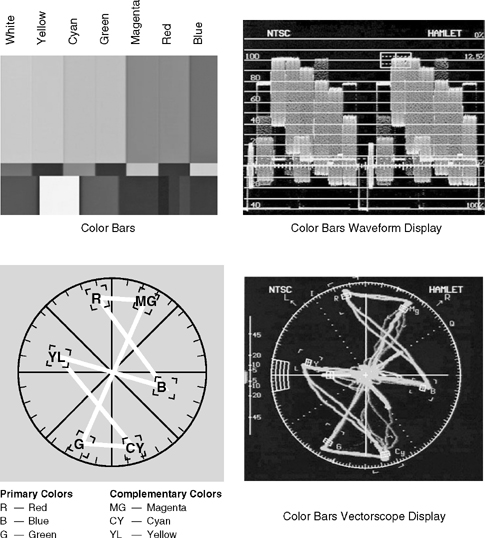
Although color burst tells you if color is present, it does not tell you which colors are present. This is the function of a piece of monitoring equipment known as the vectorscope (see Figure CP-12). Each of the three primary colors of light (red, green, and blue) and their complements (cyan, magenta, and yellow) are marked on the face of the vectorscope. By looking at the vectorscope, you can determine which colors are present in the signal and how much of each one is present (see Figure 3.9 on page 76).
Since the vectorscope provides critical information about the color information in the video signal, it is an essential component of the monitoring system that is used by video engineers when color adjustments are made to cameras and VCRs. A standard pattern of color bars is used as a reference to make sure that all components of the color system are functioning properly. Figure CP-5 illustrates a typical color bar display, and Figure 3.9 shows how the color bar display appears on a waveform monitor and vectorscope. In multiple-camera shooting situations, the vectorscope is used to help match the color quality of the cameras so that the color values they reproduce are the same for each camera. In single- or multiple-camera operations, a vectorscope can assist in gauging whether the camera is properly white-balanced, that is, adjusted to reproduce colors correctly in the lighting conditions that exist at the recording location.
Video Monitors
Three different kinds of direct-view (as opposed to projection-system) video monitors and receivers are in wide use today: CRT (cathode ray tube), LCD (liquid crystal display), and PDP (plasma display panel) displays.
Cathode Ray Tubes. Cathode ray tube (CRT) systems are based on analog-type vacuum tube technology. The CRT is popularly called the picture tube, and the inside of the tube is covered with a series of phosphorescent dots. In black-and-white television, these dots are capable only of growing brighter or darker. In the color set, these dots are arranged in groups of three: one red, one blue, one green (see Figures 3.10 and CP-2). The color video signal, as we have seen, is composed of varying amounts of these three colors, depending on the scene that is being shot. When the color video signal is fed into a monitor, it triggers an electron gun to scan the face of the picture tube, and it activates the red, blue, and green dots on the screen in relation to their relative strength in the signal. What you see as you watch the screen is a full-color picture. Actually, if you get close enough to the screen of your television and stare at it, you can see there are really only three colors present: red, blue, and green. When you move away from the set, these three primary colors combine to form the other colors of the spectrum. Color mixing, therefore, is really subjective. It takes place in your head, not in the television system itself.
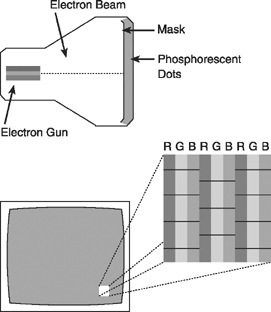
FIGURE 3.10 Cathode Ray Tube (CRT) System
Liquid Crystal Displays. LCDs are flat-panel screens widely used in laptop computers and consumer camcorder viewfinders. Because they are flat, they take up less space than CRT displays. The display relies on the use of liquid crystal material contained within the screen, which emits light when stimulated with an electrical charge. Each pixel (actually, each red, green, and blue subpixel) in the screen is excited by a tiny transistor that applies the electrical charge produced by the video signal.
Plasma Display Panels. Another flat-screen display system is the plasma display panel (PDP). PDPs use a neon gas material compressed between two layers of glass embedded with crisscrossing horizontal and vertical electrodes to excite the red, green, and blue phosphors in the screen. PDPs are capable of producing higher-quality and larger images at a lower cost than LCDs, and for this reason they are the system of choice in flat-panel HDTV displays (see Figure 3.11).
HDTV, EDTV, and SDTV Monitors. Video monitors vary in their capability to display the various NTSC and ATSC picture standards. HDTV (high definition television) monitors display either 1080 line interlaced or 720 line progressive signals in the 16:9 aspect ratio. SDTV (standard definition television) monitors display signals in the 480 line interlaced format in the 4:3 aspect ratio. EDTV (enhanced definition television) monitors display 480 lines scanned progressively. If the input signal is HDTV, the aspect ratio will be 16:9; if it is SDTV the aspect ratio will be 4:3.
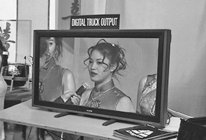
FIGURE 3.11 Flat-Screen Plasma Display Panel
World Color Television Standards
Just as there are several different television frame scanning rates and line standards in operation throughout the world, so are there differences in the way the color signal is produced and recorded. The analog U.S. system, established by the National Television System Committee, is NTSC color. Critics suggest that NTSC stands for “never twice the same color,” because the NTSC system allows for adjustment of color, hue, and saturation at the point of reception, with the result that color values may vary greatly from receiver to receiver. The NTSC system is used throughout North and Central America as well as in parts of the Far East.
In other parts of the world, two other analog color systems are also used: PAL (Phase Alternation by Line), designed by the Germans and the British and found in England, Western Europe, and throughout Africa and the Middle East; and SECAM (Système Électronique pour Couleur avec Mémoire), designed by the French and widely used in Eastern Europe and parts of Africa as well as in France and Russia. SECAM is generally regarded as the best of color systems, followed by PAL and then NTSC.
As you might imagine, these different color television standards present problems when a program produced in one format is scheduled to be shown in a country that operates in another, incompatible format. Fortunately for video producers, electronic standards converters are widely available.
Broadcast Quality
Technical standards exist by which engineers can determine whether a particular video signal is of broadcast quality. All broadcast signals fall under the jurisdiction of the FCC, which publishes specifications that all broadcast signals must meet. Of particular importance to the video field producer is the size of the horizontal and vertical blanking intervals and the pedestal or setup level. Cameras that rely on their own internal sync generators should be periodically checked to ensure that they are operating properly, especially if the tape will be distributed to broadcast outlets.
The standards of broadcast quality for different organizations often involve variables other than these technical qualities. Program content and overall production values are as much a part of broadcast quality as technical elements. The proliferation of consumer-quality camcorders provides an interesting perspective on this issue. Although inexpensive home video camcorders are generally not considered to produce broadcast-quality recorded images, videotape of news events recorded by amateur videogra-phers has become commonplace. Concerns about technical problems such as color quality and image stability may be overlooked if the content of the videotape has extremely significant news value.
The relative importance of interesting content versus technical quality extends to entertainment programs as well. One of the most popular programs on U.S. commercial television in the 1990s was America's Funniest Home Videos. Viewers submit homemade videotapes of people and animals in funny, unusual, or embarrassing situations, which are then edited for broadcast and embellished with sound effects and narration by the program’s producers. As is the case with amateur news videotapes, interesting content overrides concerns about the technical quality of images recorded on consumer-level video equipment.
Although it is always a good idea to try to achieve the highest possible technical production standards, we should note that not all media outlets require that the signal be broadcast-quality. Tapes produced for home viewing or for other kinds of closed-circuit distribution may deviate from the technical standard of broadcast quality, but the signal should still produce a clear, stable picture.
Today most consumer camcorders marketed in the United States are based on the DV (digital video) tape format. These camcorders produce a high-quality SDTV recording, particularly if equipped with three-CCD sensors. Tape shot with these systems is widely used in broadcast applications. DV has largely replaced the VHS and Hi8 analog tape formats that preceded it.
CAMERA PERFORMANCE
CHARACTERISTICS
Not all cameras perform at the same level. Depending on the number and size of CCDs, the internal electronics of the camera, and the type of lens attached to the camera, picture quality may vary significantly from one camera to another.
One or Three CCDs
Most modern video cameras contain either three CCDs or one CCD. Cameras with three CCDs are known for their excellent color reproduction and detail resolution and are almost always used in broadcast situations. However, they are not without their disadvantages. They are larger and heavier than their single-CCD counterparts, and of course they are more expensive.
Camcorders with a single CCD have become the standard in consumer-quality video equipment. Single-CCD camcorders are known for their portability and low cost. However, one does sacrifice some quality when using a camera with a single-image sensor. Usually, both resolution and color quality are not as good as they are in a three-CCD counterpart.
CCD Size
As noted above, CCDs are extremely small, typically 1/6″, ¼″, ⅓″, ½″, or ⅔″ in diameter. Generally speaking, larger CCDs produce better image quality than smaller CCDs; however, image quality is also dependent on the number of pixels in the array. The more pixels in a particular CCD, the smaller each pixel will become, resulting in an increase in the overall resolution that that CCD will reproduce.
Resolution
Resolution is a term used to describe the amount of detail that a camera is able to reproduce. It is always reported in terms of lines of horizontal resolution. Think of a series of extremely narrow vertical lines. If the lines are very narrow and very close together, they will be more difficult for the camera to “see” than if they are thicker and farther apart. High-quality cameras have much greater horizontal resolution than low-quality cameras have. For example, an inexpensive single-chip camera may provide only 250 lines of horizontal resolution, whereas a high-quality camera equipped with three CCDs may provide 600 to 700 lines. This figure is a measure of the camera’s ability to reproduce fine detail in a picture. The higher the number, the greater the detail the camera can reproduce.
Video engineers use a standard resolution chart to determine how much resolution, or detail, a camera is able to produce (see Figure 3.12). High-quality cameras are generally able to reproduce much greater fine detail in a picture than do low-quality cameras.
Do not confuse this measure of a camera’s resolution ability with the number of scanning lines in the picture. All cameras operating in the NTSC system will produce pictures using the 525-line scanning standard; however, some cameras will produce pictures that are sharper or clearer than others. This difference in sharpness or clarity results from differences in the resolution ability of various cameras.
No matter how good the camera is, the amount of resolution, or detail, apparent in the image at its final display point will be only as good as the weakest link in the recording and transmission system. Most home television receivers produce an image with approximately 300 lines of horizontal resolution; VHS VCRs record the signal with 250 to 300 lines of resolution. This may increase to 400 lines when DV, VCRs are used with compatible monitors. High-quality television studio monitors may be able to resolve 600 to 800 lines.

One of the principal picture advantages of HDTV is its ability to reproduce greater image detail than conventional NTSC video. This is the result of the greater number of pixels available in HDTV systems. For example, a traditional NTSC CCD array in the 704-pixel-per-line-by-480-line format contains 337,920 pixels per chip, whereas HDTV arrays in the 1,920-pixel-per-line-by-1,080-line format contain 2,073,600 pixels per chip, and those in the 1,280-pixel-per-line-by-720-line format contain 921,600 pixels! Cameras and monitors built to the HDTV standards are capable of delivering resolution in excess of 1,000 lines, so it’s not hard to understand why HDTV pictures are often described in terms of their sharpness and lifelike detail.
Color Reproduction
The quality of color produced by the camera varies depending on the number and type of CCDs used and the lighting conditions. Color reproduction by high-quality CCDs is exceptional, although three-CCD cameras generally produce pictures with better color than their single-chip counterparts. In both systems, the amount and quality of the light falling on the subject make a critical difference in the quality of the final picture.
Sensitivity to Light and Operating
Light Level
The operating light level of a camera varies with the number and size of image sensors in the camera, the type of lens, and the type of system used to break incoming light into its components for color processing. Not long ago, the operating light level for color cameras was in the range of 400 footcandles. Today, the highest-quality cameras can produce excellent pictures with 150 to 200 foot-candles of light, and many cameras provide excellent color with low noise at 50 foot-candles and less. (Foot-candles will be discussed in more detail in Chapter 7.)
Most CCD-type cameras and camcorders can produce excellent color pictures in extremely low light. Two guidelines should always be followed with respect to the amount of light required for the optimum performance of your camera system. First, read the camera operation manual, if available, to learn the manufacturer’s recommendation. Second, check with your engineering staff (if you have one!) for their recommendations.
Signal-to-Noise Ratio
The signal-to-noise ratio (S/N) is the ratio of the total signal to the electronic noise produced by the camera. It shows how much higher the signal level is than the level of noise. Expressed in decibels (dB), the larger the value is, the crisper and clearer the picture will be during playback. For example, a camera with an S/N ratio of 62 produces a much better picture with less electronic noise than a camera with an S/N of 54.
CCD Image Problems: Smear and Moiré
CCDs are susceptible to smear and moiré effects. Smear is a unique type of image distortion caused by very bright illumination in which a bright vertical band appears above and below the bright object in the picture (see Figure 3.13). Automobile headlights and high-intensity streetlights frequently produce CCD smear effects. Moiré is caused by photographing subjects that have high-contrast fine detail—for example, a shirt with a light and dark pinstripe pattern or a herringbone fabric pattern. The resulting image created will appear to vibrate on the screen.

CAMERA
CONFIGURATIONS
Modern video cameras are available in a number of different configurations. These include camcorders (in either a one-piece unit or a dockable system) and convertible cameras that may be used in either a studio setting or a remote field production setting. A third group of cameras include large-scale models designed primarily for in-studio use.
Camcorders
A combination camera and VCR, or camcorder, combines the camera and recorder into one easily carried unit (see Figure 3.14).

FIGURE 3.14 Professional One-Piece Camcorder
Camcorder systems designed for broadcast applications use highquality three-CCD cameras. These professional-quality camcorders may be one-piece systems or dockable systems. Dockable cameras are designed to be connected to a special docking VCR to create a camcorder unit. Highquality docking VCRs are available in a variety of professional video recording formats.
One-piece camcorders in the DV format have become immensely popular and are widely used by home video producers and other producers not requiring the quality of the most expensive broadcast-quality camcorder systems. The camera portion of DV consumer-level camcorders almost always utilizes a single CCD as the image sensor, while prosumer and professional models use three CCDs.
Most one-piece consumer-level camcorders are designed to operate independently from other cameras or camcorders in a field recording situation. These portable camcorders are equipped either with eyepiece-type viewfinders or fold-out LCD viewfinders.
Convertible Studio/Field Cameras
Convertible cameras are designed to be used either in the studio or in the field with several others in a typical multiple-camera configuration or as single-camera portable units in the field. In a typical field situation, the camera is connected to the recorder by a long or short cable. In other situations, the camera output can be sent via microwave either to the recorder or back to the station for broadcast.
Convertible cameras are generally smaller and cheaper than their full-size studio counterparts, may be equipped with either an eyepiece or a studio-type viewfinder, and may be operated with conventional AC power, or with battery power. (See Figure 3.15.) Some convertible cameras have the capability to be converted into camcorders by removing the back end of the camera and adding a dockable video recording device.
Two main characteristics distinguish these convertible cameras from others. First, they have the capability to be outfitted with either a studio viewfinder or a small-eyepiece viewfinder. In the studio configuration (see Figure 3.16), the camera operator stands behind the camera, which is usually mounted on a tripod or camera pedestal. Because the operator stands behind the camera, the camera viewfinder must be mounted on top of the camera. Usually, the viewfinder has a fairly large (approximately 5″ in diagonal) viewfinder screen, so the camera operator can easily see the image. In addition, convertible cameras can easily be adapted so that the zoom lens controls and lens focus controls are removed from the lens itself and are instead mounted on panning handles that protrude from either side of the rear of the camera. As a result, the camera operator can easily see the viewfinder image and make zoom lens and focus changes while standing behind the camera.

The second characteristic of convertible cameras is that they are capable of being operated synchronously with the other cameras. In order to be able to do this, the camera must be able to accept an external sync signal. Usually, the camera has a small input through which the sync generator can be connected. The sync generator provides the composite sync pulses (horizontal and vertical) simultaneously to all the cameras.
In addition, when the camera is used in a multicamera production (studio or field), the camera output is fed into a video switcher rather than into its own VCR.

FIGURE 3.16 Convertible Camera in Studio Configuration with Tripod and Dolly
Studio Cameras
Some video cameras are designed primarily for use in studios. They tend to be much larger than their field production counterparts, are equipped with large studio-type zoom lenses, have highly developed internal signal adjustment circuitry, and usually do not have the capability to be operated by battery power. (See Figure 3.17.)

CAMERA VIEWFINDER
SYSTEMS
The camera viewfinder is the part of the camera that the camera operator looks into to see what is being shot. Electronic viewfinders are found on all high-quality video cameras. The viewfinder is actually a small video screen. When you look into it, you see what the image sensor sees. In the past, viewfinders displayed only a black-and-white picture, even on most color cameras. However, today an increasing number of color cameras incorporate color viewfinders. Camera viewfinders come in two configurations: studio and remote (eyepiece) (see Figure 3.18).
A studio viewfinder is mounted on top of the camera. Usually, it produces an image that is approximately 5″ in diagonal. Studio viewfinders allow the camera operator to stand behind the camera as shots are composed and focused.
The remote eyepiece viewfinder is usually mounted on the side of the camera. It contains an eyepiece that allows the videographer’s eye to be put firmly against the camera. This prevents natural light from hitting the small screen inside the eyepiece and washing out the picture. Viewfinders of this type are usually quite small, often approximately 1½″ in diagonal. More expensive eyepiece viewfinders can be rotated in numerous directions so that the camera can be held in positions other than on the shoulder.

An increasing number of consumer and professional cameras and camcorders also are equipped with a color LCD (liquid crystal display) viewfinder. This viewfinder system not only makes it easier to view the image as it is played back through the camcorder but also allows the videographer to see the viewfinder image while the camcorder is held at arm’s length, making it possible to record from difficult or unusual angles (for example, overhead) that might not have been possible with a conventional-eyepiece viewfinder system (see Figure 3.19 ).

Camcorder viewfinders usually contain electronic displays that indicate whether the lens aperture setting is correct. They also contain indicators that monitor the status of the VCR: record mode, play mode, the amount of battery power remaining, the tape counter number, and so on.
Finally, on most portable cameras, a scene that has just been recorded can be played back and viewed in the viewfinder in order to check the quality of the recording. Some cameras and camcorders contain a small audio speaker that allows you to monitor the sound as well.