CHAPTER 4
Operating the Video Camcorder
THE BASIC SYSTEM
Today most small-scale EFP and ENG recording is done with a camcorder (see Figure 4.1). Camcorders contain two components: a video camera and a portable video recorder. With these two components you can shoot and record electronic images. The camera section produces the basic video signal, which is then sent to the video recorder.

FIGURE 4.1 Recording in the Field with Professional Camcorders
The camera and recorder may be manufactured as a single unit in which the camera and recorder are inseparable, or the camera and recorder may be manufactured as separate, dockable units in which the camera outputs and recorder inputs can be directly connected together to create the camcorder unit. Consumer-quality camcorders are typically one-piece systems, while a professional-quality camcorder may be either a one-piece or a dockable system.
Prior to the development of camcorder systems, single-camera video field production was accomplished using recording systems composed of a portable video camera tethered to a portable VCR with a camera cable. Although several manufacturers still produce stand-alone portable VCRs, today the vast majority of single-camera field production work is recorded using one-piece or dockable camcorders (see Figure 4.2).
In addition to these principal components, the camcorder system may have any number of auxiliary components. These auxiliary components may include power components (including both batteries and alternating current [AC] adapters), monitoring devices (equipment that lets you see the picture and hear the sound), lighting instruments, and additional audio equipment. Lighting and audio are the subjects of separate chapters.

FIGURE 4.2 One-Piece and Dockable Camcorder and Dockable VCRs
While the vast majority of camcorders in use today rely on videotape as their recording medium, the videotape recording process is being augmented, and will ultimately be supplanted, by video recording onto optical discs, magnetic computer hard drives, and memory cards. These new media are discussed in greater detail in Chapter 5. The discussion in this chapter will focus on the operation of videotape-based camcorders.
COMMON CAMCORDER CAMERA
SECTION CONTROLS
Power Switch
All camcorders need to have a source of power supplied to them. Power can be supplied directly by a battery (DC—direct current) or by an alternating current (AC) adapter connected to wall current.
The power switch turns the camcorder on and off. Some camcorders include a standby switch, which allows the camera electronics and image sensor to warm up but does not cause the sensor to produce an image. In this way, it increases the life of the sensor and prolongs the life of the portable battery power system. It also lets you keep your camera ready to shoot without using as much power as in the “on” mode. Other switch configurations allow you to power up the camera and VCR sections independently for those situations when you want to use the camera section to produce an image without recording it, or, conversely, when you want to use the VCR section to play back a tape for viewing without recording a signal from the camera. (See Figure 4.3.)

FIGURE 4.3 Camcorder Camera Section Controls
VCR Trigger
The VCR trigger is a small button, usually located at the back of the lens assembly, that is readily accessible by the camera operator’s right thumb. The trigger gives the camera operator control over the recording process while operating the camcorder. Pushing the trigger and releasing it start and stop the VCR when it is in the ready-to-record mode.
Quick Record
As an alternative to first powering up the camcorder and then pushing the VCR trigger to begin recording, many professional camcorders contain a quick-record button. This allows the camera operator to bypass the standby mode and instantly put the camcorder into the record mode. This feature is most useful to ENG photographers when they have to quickly begin recording because of the nature of the event they are covering.
Gain Boost/Sensitivity
The function of the gain boost switch is to amplify the video signal. This is most often used in low-light situations when the camera won’t produce an acceptable picture even with the lens aperture fully opened up. Color cameras have a tendency to perform poorly when they do not have adequate light. The gain boost strengthens the signal and provides somewhat better color reproduction in these low-light situations. However, the benefit is not without a cost. As with any radical adjustment of the gain, the picture quality is usually somewhat degraded due to the increase in visual noise in the signal. And if you engage the gain boost while shooting a well-lit scene—for example, outdoors on a sunny day—you will almost certainly make the picture look worse.
Color Correction Filters
Most professional and prosumer cameras and camcorders contain a series of filters that are used to compensate for differences in the color temperature of the light falling on the scene. (Color temperature is discussed in more detail in Chapter 7.) The two most essential settings are 3,200°K (equivalent to the color temperature of tungsten-halogen lights used in television studio production) and 5,600°K (equivalent to the color temperature of daylight). On consumer equipment, these switches may be labeled “INDOOR” and “OUTDOOR.”
Professional cameras are likely as well to have one or more neutraldensity filters. These filters reduce the amount of light that reaches the image sensors, without affecting the color temperature of the light. The neutral-density filter is typically used in conjunction with the lens iris when shooting outdoors in very bright conditions in order to control depth of field. Under very bright outdoor lighting conditions, the lens will generally produce an image with great depth of field; that is, objects close to and far away from the camera will be in focus. In order to shorten the depth of field so everything is not in focus, the neutral-density filter is engaged, which then requires the lens iris to open up to let in more light. As the iris gets larger, depth of field gets shorter. This allows the camera operator to exercise a degree of aesthetic control over the portions of the image that are in focus and those that are out of focus.
White and Black Balance
Because the color temperature of light varies so much, all color video cameras contain electronic circuitry designed to correct the white balance of the camera. White balance adjusts the relative intensity of the red, green, and blue color channels to allow the camera to produce an accurate white signal in the particular light in which the camera is recording. Once the camera is set to produce white accurately, it can produce all of the other colors in the scene accurately as well.
There are three common white balance modes. Automatic white balance continuously and automatically regulates the camera’s electronic color circuitry even if the color temperature of the light changes while the camera is recording the scene.
Preset white balance controls allow the camera operator to manually choose from a variety of preset settings such as 3,200°K (tungsten-halogen) or 5,600°K (daylight), or from a menu of various light sources such as incandescent, fluorescent, daylight, and overcast lighting conditions.
Manual white balance controls require the camera operator to set the white balance for the existing light conditions by focusing the camera on a white card and activating the manual white balance switch. If the lighting conditions change, or if the camera changes position, the white balance procedure needs to be repeated.
Professional cameras may include a black balance control in addition to white balance. Black balance adjusts the video signal to produce black at a preset point in the video waveform.
Color Bars
All professional-quality camcorders now available have a color bar switch. This switch causes the camera to generate a standard NTSC color bar output. These color bars are a standard pattern of yellow, cyan, green, magenta, red, and blue bars and are used as a standard color reference by video engineers. It is a good idea to record at the head of each field tape some color bars generated by your camera. This can be used as a color reference when it is time to play back your tape.
Camcorder Special Effects
and Image Stabilizers
An increasing number of camcorders have the ability to record a variety of special effects produced digitally within the camcorder. These may include a still picture effect, which freezes the moving video image and records it as a still image; a strobe effect, which breaks the incoming video signal into a series of still images to create a stroboscopic motion effect; and a time-lapse recording effect, in which the camera can be set to record one or more frames of video at predetermined intervals.
Digital zoom effects can be used to enlarge an image significantly beyond the magnification possible with the zoom lens. This has the effect of producing even closer close-ups, but may also increase the graininess of the picture.
Although it is not a special effect, camcorders equipped with a digital image stabilizer process the incoming signal to reduce the motion artifacts created when the camera operator shakes the camera—a problem that is particularly evident when the lens is zoomed in on very tight close-up shots. One unfortunate side effect of this feature is that if the stabilizer is left on while the camera operator is shooting a stationary subject with a steady camera, the image stabilizer may actually introduce motion into the image and cause it to appear to be out of focus.
VCR SECTION CONTROLS
AND INPUTS/OUTPUTS
The VCR section of the camcorder contains these important components (see Figure 4.4):
1. Tape transport controls
2. Audio and video inputs and outputs
3. Power inputs
4. Meters, warning lights, and tape counters
Tape Transport Controls
The tape transport controls regulate the movement of the videotape within the VCR. You will be familiar with these controls if you have ever operated a camcorder of your own:
![]()
Eject. This button is used to eject the tape from the machine or to insert a tape into the machine. Most VCRs have a safety device to prevent you from ejecting the tape while the machine is running, but it is nevertheless a good idea never to eject the tape unless the machine has been stopped.

![]()
Play. This causes the tape to move forward at a normal speed; it is used to play back a tape.
![]()
Slow-Speed Playback. When the tape is in the play mode, pressing this button reduces the tape playback speed to a preset slow speed.
![]()
Stop. To stop the movement of the tape in any mode, press STOP.
![]()
Fast Forward. Pushing this button with the VCR in the stop mode causes the tape to move forward at a fast rate of speed. You do not see the picture or hear the sound when the VCR is engaged in fast forward because the tape is not in contact with the heads. Use the fast forward button when you want to find a spot that is a considerable distance into the tape.
![]()
Rewind. This functions the same as the fast forward button except that it moves the tape in the opposite direction.
![]()
Pause. When the tape is in the play mode, pressing the pause button will stop the movement of the tape and give you a still frame. The tape remains engaged against the heads so that you can still see the picture. Do not leave the tape in the pause mode for more than a few minutes, as this may damage the tape by subjecting it to excessive wear. Many machines will automatically stop and release the tape from the heads if the machine is left in the pause mode for more than a few minutes.
![]()
Forward/Reverse Frame by Frame. With the VCR in the pause mode, this control advances or reverses the tape one frame at a time.
![]()
Forward Search and Reverse Search. Many machines incorporate forward- and reverse-search controls. These allow you to forward or reverse the image at a high speed when the VCR is in the play mode. Unlike the fast forward and rewind controls, the tape is not released from the head drum. As a rule of thumb, this mode should be used only to move the tape relatively short distances in either direction. If more than a few minutes of forward or reverse movement are necessary, use the fast forward or rewind button.
![]()
![]()
![]()
Record. The record button is used to record new audio and video onto videotape. Some machines have one-touch recording, which puts the VCR into the record mode when you simply push the record button. Other machines require you to push and hold the record button and then to simultaneously press the play button to engage the recording function.
![]()
Audio Dub. This is used to record new audio information onto a prerecorded tape without erasing the video information already recorded on it. It is engaged in the same way as the record button: press the audio dub button in conjunction with the play button.
Audio and Video Inputs
and Outputs
Because VCRs record both pictures and sound, there are a number of audio and video inputs and outputs on these machines (see Figure 4.4).
Audio Inputs and Outputs. If audio is generated by a source other than the camera microphone, a number of additional inputs are available to route the signal into the VCR. Microphone-level inputs are used for un-amplified sources, and line-level inputs are used for sources that have been amplified.
An external microphone can be connected to the microphone in connection; line-level audio signals from another VCR, audiotape recorder, and so on can be connected to the audio in (line) jack. Audio outputs can be used in conjunction with the video output or independent of it. The audio output signal, audio out (line), can be connected to a monitor so that the sound can be heard. Or it can be connected to another VCR or audio recorder to record the audio output signal. Professional-quality camcorders contain the normal series of audio and video inputs and outputs on the body of the camcorder. On consumer-quality camcorders, connectors for additional line-level audio and video inputs and outputs may be found on the camcorder or on the AC power adapter.
Video Inputs and Outputs. Sometimes a video source other than the camera provides the video signal to the VCR. For example, the signal from another VCR may be transferred to your camcorder and recorded on it. In this case, the auxiliary video input (also called video in) would be used. The video output (video out) can be used to connect the output signal of the camcorder to a monitor or to send the signal to another VCR. In addition to conventional video inputs and outputs, DV camcorders have S-Video connectors, where the luminance and chrominance signals are kept separate; DV camcorders may also have a FireWire connector to allow the input or output of a digital video signal.
Power Inputs
All portable VCRs are powered by a 12-volt direct current (DC) power source rather than by standard household 120-volt alternating current (AC). If AC current is used, a special AC adapter that converts household current to 12-volt DC is needed. AC adapters usually connect to a special four-pin connector on the outside of the VCR case.
Because the batteries used with portable VCRs all deliver 12-volt DC, no special adapters are needed for their use. The electrical contact points on the battery are exposed, and the proper connection is made by correctly inserting the battery into the camcorder’s battery holder.
Meters,Warning Lights,
and Tape Counters
All high-quality VCRs contain a series of meters for monitoring different machine functions. In many camcorder systems, even the most inexpensive consumer-level systems, displays for many of these metering functions are shown in the camera’s viewfinder while recording.
Battery Meter. The battery meter is used to monitor the level of power in the battery. Typically, this is a viewfinder display.
Volume Unit Meters. All professional equipment contains a volume unit (VU) meter to monitor the level of the audio and/or video input. A VU meter contains a scale that is a standard calibration of signal strength used in all broadcast and nonbroadcast media facilities. A small needle or LED display indicates how high or low the signal is. Camcorders typically incorporate an LED audio-level display. This display may be located on the side of the camcorder near the audio gain controls (if the camcorder is so equipped), or it may appear as a viewfinder display.
Warning Lights. Many VCRs come equipped with a variety of warning lights that tell you if something is wrong. The dew lamp warns you that moisture or condensation has formed on the head drum. Because the videotape must glide smoothly over the head drum and moisture can make the tape sticky, the dew indicator is extremely important. If it comes on, it means the head drum is damp and the VCR will not make a satisfactory recording. Sometimes this happens if the camcorder has been stored in a damp place or if it has been moved from outdoors to indoors. If the dew warning lamp comes on, push the eject button, remove the tape, and allow air to circulate inside the VCR. The problem will usually correct itself in a few minutes. Many viewfinder displays also contain a tape end warning that lets you know when you are a minute or two from the end of the tape.
Tally Light. The tally light is a small red light, typically located at the front of the camcorder, that illuminates when the machine is in the record mode.
Tape Counters. Three selections are commonly found for the tape counter: CTL, TC, or UB.
CTL stands for “control track.” Analog consumer-quality camcorders, which are not equipped with a SMPTE time code generator, use the control track pulses (see Chapter 5 for a discussion of the control track) on the videotape to display the tape position in hours, minutes, seconds, and frames. However, for the display to be accurate, the counter must be set to zero at the beginning of the tape. Since control track pulses do not contain data—they are simply electronic pulses on the tape—anytime the reset button is pushed the counter will reset to zero. Many professional camcorders contain a CTL counter as well as TC and UB counters.
TC stands for “SMPTE time code.” Professional VCRs and camcorders use SMPTE time code counters, and even consumer-level DV camcorders generate and display SMPTE time code. These counters display the SMPTE time code value for the current position of the tape. SMPTE time code counters are the most accurate tape counters available. UB stands for “user bits.” This is a feature on some SMPTE time code-enabled systems that allows the user to enter additional information about the shot or scene that is being recorded.
Other Controls
Video Input Selector. The video input selector switch tells the VCR where the input video signal is coming from. The switch typically has two positions: camera and VCR/line. To record a video signal from the camera, the input switch must be in the camera position. When using the VCR to record a video signal from another VCR or to play back a tape through the camcorder without engaging the camera section, the VCR/line position is used.
On some one-piece consumer-level camcorders, this control may be integrated with the camcorder’s power switch, which may have “camera” and “VCR” positions. In the “camera” position, the VCR section records the video signal that the camera section of the camcorder is generating. Recording is stopped and started by using the stop/start button located on the zoom lens assembly. When the selector plate or power switch is in the “VCR” position, the camcorder can be used to play back a recorded tape or to record a video signal from another VCR.
Audio Input Selector. This control tells the camcorder where the audio signal is coming from—microphone, camera, or line.
Audio Mode Selector. This selector controls the audio record and playback functions of the VCR and the VU meter display on VCRs that are capable of recording and playing back normal and high-fidelity (or digital) audio signals. Digital video (DV) format camcorders usually incorporate the audio mode selection as a choice within the onscreen menus that control camera functions (see Figure 4.5). Typically, you will be able to set the camcorder to record either two channels of top-quality audio, or four channels of lesser-quality sound.

Audio Monitor Control. On camcorders with two audio channels, the audio monitor control determines which audio channel is heard in the earphones or camcorder audio monitor speaker. In the channel 1 position, only audio channel 1 is heard; in the channel 2 position, only channel 2 is heard. In the mix position, both channels are heard simultaneously. The audio monitor control does not affect the way the audio signals are recorded; it affects only what you hear when you are monitoring the audio during recording or playback.
Tracking Control. On older analog VCRs, the tracking control is used in the playback mode to maximize the quality of the playback image by compensating for slight differences in the way different VCRs record and play back a signal. Without adjusting the tracking control, something recorded on one machine may not play back correctly on another machine due to the slight mechanical differences between the VCRs.
The tracking control should always be set in the fixed position when recording. This position is usually marked on the control, and there is a small notch in the fixed position where the control clicks into place. In modern digital camcorders, tracking is adjusted automatically by the VCR during tape playback, so there is no manual tracking control on the VCR.
Remote Controls. Some VCRs contain a remote control input that allows the operator to control the tape transport system with a remote control unit. The remote controls duplicate the standard tape transport controls.
Other Features
of Videocassette Recorders
Most camcorders’ VCR sections contain several other features that deserve at least a brief mention.
Automatic backspace editing gives clean cuts from shot to shot when you are recording and using the camera trigger at the beginning and end of each shot. When you push the record trigger at the end of a shot or sequence, the VCR stops and then automatically backs the tape up a few frames. When you push the trigger to begin recording the next shot, the tape rolls and then begins the new recording in sync with the previously recorded material. The effect is that of a clean cut, or edit, from one shot to the next, without any blank tape or image break between the two shots.
Video insert (called video dub or video add on some machines) allows you to insert new video into a previously recorded segment. This feature gives a clean entrance to and exit from newly inserted video.
POWER AND
VIDEOTAPE
Power for the Camcorder
All portable camcorders can be powered by a battery or by standard AC power through the use of a special AC adapter. Your choice of power source depends on the recording situation and the available equipment. If you are using a consumer-quality camcorder to record your grandmother’s birthday party indoors at home, you can choose between an internal camcorder battery or external AC power because of its availability. However, if you’re recording an interview with a geologist who is surveying an earthquake fault at a remote mountain site, you will probably have to rely on batteries. Most camcorders use internal batteries that are inserted into the camcorder or clip-on battery packs that attach to the back of the camcorder with a special adapter.
Battery Types. Three different types of batteries are used to power video camcorders. Consumer-level equipment typically uses lithium ion (Li-Ion) batteries, which are considerably smaller and lighter than the nickel cadmium (NiCad) and nickel metal-hydride (NiMH) batteries used in most professional equipment. NiCad and NiMH batteries can power a camcorder and camera light; Li-Ion batteries cannot. While NiCad batteries need to be drained of power before they are recharged, Li-Ion batteries do not.
Since access to a reliable source of power is essential for video recording, the importance of having enough fully charged batteries available on a shoot cannot be overemphasized. After the batteries have been discharged, slow (trickle) or fast (quick) battery chargers can be used to recharge batteries in the field or overnight between shooting days.
AC Power Adapter. As mentioned earlier, AC adapters convert 120-volt household alternating current into the 12-volt direct current that video recorders and cameras run on (see Figure 4.6). They can also be used to charge spare camcorder batteries. One end of the AC adapter plugs directly into a wall outlet and is equipped with a standard three-pronged AC connector. The other side of the AC adapter is equipped with a connector that attaches to the camcorder.
Consumer camcorders use a variety of power connectors that are unique to each camcorder/manufacturer. Professional equipment uses a rugged four-pin XLR connector (also called a Cannon connector).
The AC adapter also has an on/off switch. Two cautions should be observed when connecting the AC adapter to a camcorder:
1. Make sure that the AC adapter is turned off when you plug it into the wall and the camcorder. Do not turn it on until you have made all connections correctly.
2. When you connect the AC adapter to the camcorder, make sure you make the connection correctly.
If the pins of the AC adapter are not inserted into the correct holes on the camcorder, you might blow a fuse in the deck and will be unable to operate the machine until the fuse is replaced. The pins are arranged so that you can insert the connector correctly in only one way.
At this point, a suggestion with respect to making connections is in order: don’t force anything. Many of the receptacles (and some of the plugs) found in portable equipment are made of plastic. If forced into an incorrect connection, they will break. Always examine the pin configuration before you attempt to connect a piece of equipment.

FIGURE 4.6 AC Adapter/Battery Charger
Inserting the Videocassette
All videocassettes have a top and a bottom. The top of the cassette is a smooth piece of plastic; the bottom contains the recessed portion of the tape spools. In addition, each tape has a front and a back. The back of the cassette is a solid piece of plastic and the front has a small metal or plastic door.
In order to insert the tape into the machine, push the eject button on the camcorder. This will cause the tape carriage (the part of the machine that holds the tape) to pop open. (Note: In most portable systems, the eject button will not work unless the camcorder has been connected to battery or AC power.) Carefully insert the tape into the carriage with the door away from you and the open spools to the inside of the VCR, and then insert the tape as far as it will go. Then push down on the carriage assembly to close the door and lock the tape into position.
Tape Movement Inside
the Camcorder
What happens to the videotape when you insert it into the tape carriage and push it down into the VCR? Several things happen inside the camcorder. First, as the tape carriage is depressed, the small door on the front of the videocassette opens automatically. The door acts as a shield to protect the tape when it is outside the machine. But for the tape to operate within the machine, the tape must be withdrawn from the cassette and brought into contact with the video heads. So a small device triggers the door to release, and the door pops open.
What happens after the tape is inserted into the camcorder and the door is opened depends on the mode or function selected for the VCR section. In the stop mode, the tape stays within the cassette and does not move. In the fast forward and rewind modes, the tape is driven forward or in reverse at a high speed. Again, the tape remains entirely within the cassette housing.
However, in the record and play modes (including forward and reverse search, pause, single-frame advance and reverse, and slow-speed playback), something very different happens. In order for a VCR to play back a tape or record onto a tape, the videotape must be brought into contact with the video heads. The video heads lay down the signal in the record mode and read the signal on the tape in the play mode. The video heads are located within the head drum—a small stainless steel cylinder inside the VCR. In order for the tape to make contact with the heads, a mechanical arm reaches inside the cassette, physically pulls the tape out of the cassette, and wraps it around the head drum. This is a complicated mechanical operation and demands that the mechanical arm and tape guides be precisely adjusted and aligned (see Figure 4.7).

This mechanical method of extracting the tape from the cassette housing is one of the greatest trouble areas with portable equipment, particularly older VCRs. When the mechanism malfunctions, the tape gets “eaten” by the machine. Anyone who has ever worked with portable equipment for any amount of time has seen a tape chewed by a VCR.
CAMCORDER
SYSTEM SETUP
Let’s assume that you simply want to record some video and audio information onto videotape with your portable camcorder. To make matters even simpler, we will assume that you plan to use the microphone that is built into your camcorder. How to proceed varies slightly, depending on the particular features of your camcorder. In general, these steps apply to the setup of most simple one-piece camcorder systems:
Step 1. With the power switch off, make sure the camcorder is secure (either mounted on a tripod or resting safely on a hard surface).
Step 2. Connect the camcorder to power by inserting the internal battery into the camcorder and connect an external battery if one is available.
Step 3. Turn on the power to the camcorder. The power light should illuminate.
Step 4. Open the tape carriage door by pushing the eject button. Insert the videocassette carefully and correctly. Close the tape carriage. Rewind the tape to the beginning.
Step 5. Set the filter and white balance controls to their proper positions for the lighting conditions in which you will be recording. Set the gain boost to normal.
Step 6. Uncap the camcorder lens. An image should be visible in the viewfinder.
Step 7. Look through the viewfinder. Frame up and manually focus the image (or set to auto-focus). Set the iris to automatic (or manually adjust the aperture for correct exposure). White balance the camera.
Step 8. Push the record trigger button to begin recording. Make a brief test recording.
Step 9. Push the record trigger button to stop the recording. Rewind the tape to the beginning, and check your recording by watching it in the viewfinder. Use an earphone to monitor the recorded audio, or listen to it through the earspeaker if your camcorder is so equipped.
AUDIO AND VIDEO
CONNECTORS
Quite often in field production, you need to go beyond the simple setup just described. Most camcorders contain a series of auxiliary audio and video inputs and outputs. These additional inputs and outputs are used when you want to record from a video or audio source other than the camera or camera microphone into the VCR section, when you want to monitor the output of the VCR section, or when you simply want to play back a tape into a monitor to check its quality.
A big problem with auxiliary inputs and outputs on portable equipment is that the connectors used have not been standardized. As a result, you need to become familiar with the range of video and audio connectors in use, and in particular, you need to know which specific connectors are used on your equipment. Figures 4.8 and 4.9 illustrate the most common audio and video connectors found on portable video equipment.
Audio Connectors
The most common use of additional inputs is for recording audio. The quality of the audio recording can almost always be enhanced by using an external microphone rather than the camera microphone.
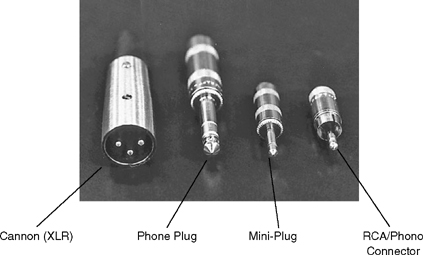
FIGURE 4.8 Audio Connectors

Professional equipment uses a three-pin XLR (Cannon) connector for all audio inputs and outputs. (See Figure 4.8.) Consumer-quality DV equipment utilizes the RCA/phono connector, a small pin surrounded by a metal sheath, for line-level audio inputs and outputs. (Line-level signals will be discussed further in Chapter 8.) Microphone inputs are typically mini-plugs, small single-pin connectors. Mini-plugs are also used for the earphone jack, which is used to monitor the sound as it is being recorded. Once very popular, but now becoming less widely used, are phone plugs. These large pin-type plugs are sometimes used as headphone connectors and occasionally for microphone inputs on audio mixing consoles.
Video Connectors
Many camcorders have a series of video inputs and outputs that are independent of the video input from the camera. For example, if you want to dub a videotape from one VCR to another, the video output from one machine can be connected to the video input on another machine. On professional camcorders, video inputs and outputs will be BNC connectors (see Figure 4.9). Bayonet (BNC) connectors are twist-lock connectors, the type of connector used on almost all professional equipment.
Another type of connector used for video is the RCA/phono connector. This type is most often found on consumer-quality camcorders; it is the same type of connector sometimes used for audio.
VCRs with S-Video connectors and outputs use a special four-pin connector that is used to make direct S-Video connections (separate luminance and chrominance signals) between VCRs, cameras, and monitors that are equipped with similar connectors.
And finally, DV (digital video) equipment may use a six-pin digital video connector known as FireWire, or IEEE 1394, to move digital video (as well as audio, time code, and machine control commands) from one DV VCR to another, or from a DV VCR directly into a computer equipped with a FireWire input. On Sony equipment this connector is called iLink.
One other type of connector deserves mention. The radio frequency (RF) output of home VCRs and DVD players is carried by a coaxial cable with an F-connector. The RF output carries audio and video superimposed onto a carrier frequency, which allows you to play back a videotape or DVD and watch it on a conventional television. If you have cable television, you are already familiar with the F-connector—the cable ends in a small sleeve and a small, thin copper wire protrudes from the center of the cable. If your television has a female F-connector on the back, you can connect the cable (or VCR RF output) directly to the television.
MONITORING
THE RECORDING
Video field producers are always concerned that the scene being shot is actually being recorded on the videotape. What options are available to the field producer for monitoring the quality of the signal and recording? First, the visual quality of the image can be monitored in the camcorder’s viewfinder. This shows the camera operator what the picture that the camera section is sending to the VCR looks like. Most of the new generation of digital camcorders come equipped with a flip-out color LCD viewfinder, in addition to the standard eyepiece viewfinder. Second, the audio quality can also be monitored like the video. Headphones, or an earphone, can be connected to the camcorder, or the side panel of the camcorder may be equipped with a built-in earspeaker—a small speaker that allows the camera operator to hear the sound input directly without the use of headphones or an earphone.
Audio Meters and Gain Control
Audio can also be monitored through the use of the volume unit (VU) meter. This meter indicates the level of the signal going into the VCR section of the camcorder.
All high-quality VCRs contain VU meters for audio. The level of the audio input signal can be controlled automatically through the use of the audio automatic gain control (AGC). On many camcorders, the AGC can be overridden and switched to manual gain control. Usually, there is a small potentiometer, or pot, built into the VCR to allow the operator to increase or decrease the audio level. Because control of the audio is critical to good field production, manual control of the audio signal level is extremely valuable. It is unfortunate that most consumer camcorders do not contain either audio VU meters or manual audio gain controls, because this deprives the serious producer of an element of fundamental control over the signal.
Field Monitors
There is only one foolproof method for checking the quality of a recording, and that is to play back the videotape immediately after it has been recorded.
Monitoring Through the Viewfinder. Most field producers will make a short test recording with the equipment at the beginning of the day and then immediately play it back to see that the equipment is working properly. The recording can be played back into the camera viewfinder, and audio can be monitored through the use of headphones or an ear-speaker. All you need to do is rewind the tape to the beginning of the recorded test section and then play back the tape.
However, because viewfinders on portable camcorders are black and white or low-quality color LCD displays, this method of monitoring does not allow you to check the quality of the color of your recording. To check the quality of the color that was recorded, as well as your recording’s sound and image, you need to bring a portable color monitor into the field (see Figure 4.10). A portable color monitor is a small color video monitor. For field use, these monitors should be small (a 5″ diagonal screen is usually sufficient), lightweight, rugged, and capable of being operated via either AC or DC (battery) power. A monitor capable of operating only on AC wall current is not very useful out in the field, far from a source of AC power. As the previous discussion indicates, there are several different types of devices that can be used to view television programs or to display the output of a VCR. These devices include television receivers, video monitors, and combination monitor-receivers.
Television Receivers. A television receiver is the type of television most common to all of us. Its function is to pick up a signal that is either broadcast (over the air) or cablecast (over a wire) and to display that signal as picture and sound. Television signals that are broadcast or cablecast are RF-modulated. That is, the actual video signal and audio signals are superimposed on a carrier that oscillates at a particular frequency. These different carrier frequencies correspond to different channels on home television receivers. For example, within your local community, you probably have access to several local television stations. Each station is assigned to a different channel, which in effect corresponds to the wavelength carrier that each station uses to transmit its signal.

Video Monitors. Video monitors, on the other hand, work by displaying video and audio signals that are not superimposed on a carrier. The outputs of all VCRs, when labeled video line out and audio line out, are straight video and audio outputs without the RF carrier currents. To monitor video and audio line outputs, you need a monitor—not a receiver—that is capable of displaying them.
Let’s assume that you want to monitor what you are recording in the field through the use of a combination monitor-receiver. This type of equipment has the capability to act either as a receiver or a monitor. To operate it as a monitor, switch it to the monitor mode and connect it to a power source. Then connect the audio and video outputs on the camcorder to the audio and video inputs on the monitor. To make the connections correctly, you will need to pay attention to the types of connectors used on both the camcorder outputs and the monitor inputs. Once these connections have been made, you can simply insert a tape into the camcorder and play it back. Picture and sound should appear on the monitor.
In addition to monitoring picture and sound after they have been recorded, you can also use the monitor to display picture and sound while you are recording. The signal going into the VCR section from the camera section will automatically be routed through the monitor if you have made all the connections properly. In many portable systems, the VCR does not even have to be recording for you to monitor the camera output, as long as the power to the camera section of the camcorder is turned on. This is particularly useful if you want to warm up the camera or practice camera moves without actually engaging the tape around the head drum. It saves wear and tear on the video heads and the videotape.
One word of caution is needed here: remember to keep the audio speaker on the monitor turned down if you have a live microphone nearby. If the audio speaker is turned up too high, the audio components will begin to produce feedback. This is a loud, squealing audio noise that occurs when the microphone picks up its own sound from the speaker, which is then reamplified by the audio circuits in the VCR.
CAMERA-MOUNTING
EQUIPMENT
Perhaps the most common image that people have today of video cameras is the image of the electronic news gathering (ENG) crew on a remote shoot, with the camera held on the shoulder of the camera operator, and a news reporter chasing down a potential interviewee. This brings us to the area of camera-mounting equipment. What options are there for physically supporting a camera?
Shoulder Mount or Brace
One of the most common ways to support a portable camcorder is to carry it. Early portable camera designs were awkward and had to be held in front of the camera operator (usually because the viewfinder was mounted on the rear of the camera), but current models that have side-mounted viewfinders allow the camera to be carried on the shoulder of the camera operator. These cameras utilize a shoulder mount or brace to cushion the operator’s shoulder from the weight of the camera. They consist of a contoured piece of metal with foam padding attached to the bottom of the camera. (See Figures 4.2 and 4.3.)
Some cameras contain braces that can be changed to accommodate right-handed and left-handed operators. In addition, well-designed camcorders take balance into account—the camcorder should rest evenly on the operator’s shoulder. The weight of the lens at the front of the camcorder should be counterbalanced by the battery pack at the rear of the camcorder. The camcorder should not have a tendency to fall forward or back, but should rest squarely on the operator’s shoulder.
The shoulder mount gives the camera operator the greatest amount of flexibility in the movement of the camcorder. The operator can walk easily with the camcorder, and all types of lateral or vertical camera movements are possible. However, even the strongest person can tire of holding a shoulder-mounted camcorder, and even the best camera operator will have trouble holding a steady close-up shot for any great amount of time. For these reasons, a tripod is used.
Tripod
Tripod mounts—or sticks, as they are often called because of the wooden legs on some models—are widely used in remote productions. If camera movement is not important (for example, in an interview with the subject remaining in one position), a tripod-mounted camcorder provides the greatest amount of control (see Figure 4.11).
The tripod provides a steady base for the camera. The shoulder brace is removed from the bottom of the camera, and the camera is then attached to the head of the tripod. Many tripods contain telescoping legs so that the height of the camera can be adjusted.
Tripod heads come in two types: friction heads and fluid heads. Friction heads, which are the less expensive of the two types, give fair control over camera panning (from left to right) and tilting (up and down). Smooth camera operation is achieved both by using a tripod head that is designed to accommodate the specific weight of the camera used and through practice on the part of the camera operator. Professional camera operators always use tripods with fluid heads. These are more expensive than friction heads but are designed so that it is virtually impossible to make a jerky horizontal or vertical camera movement. For very smooth, solid camera operation, the tripod-mounted fluid head is the usual choice.

FIGURE 4.11 Camera Tripod
A quick-release plate may be used to allow for quick mounting and release of the camcorder on the tripod (see Figure 4.12).
On consumer and prosumer systems where lightweight camcorders and tripods are used, a small plate is screwed onto the bottom of the camcorder. The plate then locks into place on the tripod head.
On professional systems where the camcorders are heavier, more support is needed and a sturdier mounting plate is used. The plate is screwed onto the tripod head, and the camcorder then snaps into a locked position on the plate. A lever releases the camcorder from the plate. Quick-release systems eliminate the need to attach the camcorder to the tripod head with the mounting screw (the quick-release plate is attached instead). These systems reduce the amount of time it takes to attach and detach the camcorder from the tripod.
Two attachments for the legs of the tripod are often used. A spreader is used to spread the tripod legs out to their widest stance and hold them firmly in that position. A tripod dolly is a wheeled base that can be attached to the tripod legs if movement of the tripod is desired.
Monopods
While the shoulder brace method allows for maximum mobility of the camera, and the tripod gives maximum stability, the monopod provides a compromise between the two. A monopod is a telescoping rod that is attached to the base of the camcorder and is inserted into a special belt pouch. The monopod takes the weight of the camera off the shoulder of the camera operator but also allows for movement.
Monopods were originally designed for use with cameras with rear viewfinders, but they may be used on cameras with side-mounted viewfinders as well. The main disadvantage to the monopod is that some vertical camera movements are rather awkward to achieve. To tilt up, the camera operator must literally bend over backward. To tilt down, the operator must bend forward. Although these movements may have a yoga-like appeal, in practice they can be difficult and sometimes even dangerous.

FIGURE 4.12 Tripod Quick-Release Plates
Gyroscopic Camera Support Systems
A number of manufacturers produce camera-mounting systems that incorporate gyroscopes in their design. They are often called by the trade name of the product produced by the best-known manufacturer of these systems: Steadicam. (See Figure 4.13.) Depending on the size of the camera and the corresponding size of the mounting system, it may be worn by the camera operator, as in the case of large cameras, or handheld, as in the case of small consumer-level camcorders. In either case, the use of these gyroscopically stabilized systems allows for extremely fluid camera motion, even when the camera operator walks or runs with the camera. The effect is almost as if the camera is floating through the scene.
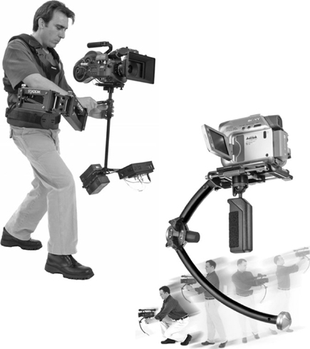
FIGURE 4.13 Gyroscopic Camera Support System (Steadicam®)
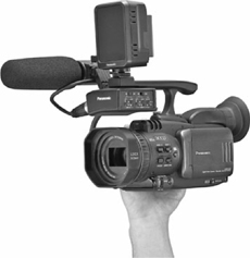
Handheld Camera
Because of their small videotape size, consumer camcorders in the MiniDV format are extremely small and light, and can easily be handheld. (See Figure 4.14.) If the camcorder is equipped with an electronic image stabilization feature, this can be used to reduce the shakiness that inevitably results from handholding the camcorder. For more professional results, use one of the mounting systems already discussed.
CARRYING
THE EQUIPMENT
It should be apparent from the previous discussion that even a relatively simple remote shoot involves the use of a significant amount of equipment. How does one carry all this gear around? A number of solutions are readily available.
Carrying Case with Shoulder Strap
Most camcorders are equipped with a carrying case, a shoulder strap, and a handle. Transport the camcorder from location to location in its case to protect it from shock, moisture, and dust. Use the shoulder strap or camcorder handle to carry it when you reach your shooting location. Remember not to swing the camcorder by the strap or handle while you are recording. Such motion can create a gyro effect, which may produce an unstable recording.
Carts
For an extremely complicated remote shoot, or in a situation where the camcorder will be augmented with the use of a field monitor, extra batteries, and additional audio or lighting equipment, wheeled carts (sometimes called crash carts) are frequently used. The carts are usually designed to hold the AC adapter, monitor, and other auxiliary equipment, and they provide convenient access to the operating controls of each piece of equipment. Some carts may even have a tripod head mounted directly onto them if stability, rather than mobility, is the primary concern.
Problems
Recordings made in the field will be more reliable and stable if the portable camcorder remains stationary while the recording is in progress. Obviously, this is not always possible. However, if you are carrying the camcorder or moving it around in a wheeled cart, try to minimize the amount of motion that the recorder is subjected to. If the camcorder is violently swung or bounced, this will almost certainly affect the speed at which the tape is moving through the VCR and introduce some instability into the recording.
Two other very common field recording problems should be mentioned briefly here.
SMPTE Time Code Problems. Interrupting the supply of power to the camcorder (e.g., removing the internal battery) can cause the time code generator in some camcorders to reset to zero. This can then cause problems during the editing process. Work-around solutions to this problem are discussed in Chapter 10.
Audio Problems. The built-in microphone on most consumer/prosumer camcorders delivers a stereo signal (two channels—left and right) to the videotape. If an external microphone is connected, depending on the type of microphone jack used the audio signal may be stereo or monaural. On professional camcorders like the one illustrated in Figure 4.4, when an external microphone is plugged into one of the microphone inputs, a monaural signal (one channel) is recorded. This also can cause problems during the editing process as the normal expectation would be that all of the recorded sound would be stereo.
A simple solution to this problem is to copy the one audio track to a second available track in the editing system, so that it is output on both the left and right channels, or to pan the track to the “center” output position in the nonlinear editing system.