CHAPTER 5
Video
Recording
In the early days of television, all programs originated from one of two sources: they were live broadcasts or they were broadcasts of programs that had originally been produced on film. Initially, there was no electronic means of storing the television image, and those programs that were aired live often disappeared forever—they were seen once at the time of the broadcast and then they were gone for good. The only way to save a live broadcast was to record the picture and sound by pointing a film camera at a television monitor during the live broadcast. Today, such film recordings of television programs, called kinescopes, provide the only record of many early television broadcasts.
Although kinescope recordings were useful in providing a historical record of what had been broadcast, they were less useful as a production device because their picture and sound quality were greatly inferior to that of the television system. What was needed was a means of electronically recording and editing the television signal. Such a system would preserve the electronic character of the television image and not distort it the way kinescope recording did. However, it was not until 1956 that the Ampex Corporation, then a small electronics company in Redwood City, California, introduced the first practical videotape recorder, which provided the first all-electronic storage and production medium for video programs. All of today’s VCRs are derived from the basic recording principles pioneered by Ampex.
With the advent of digital technologies, methods of video recording are changing. For most of the past 50 years, video recording has been dominated by the process of magnetic recording onto videotape. Today, video recording onto optical discs, magnetic computer hard drives, and memory cards is gaining popularity and may soon replace the traditional videotape recording process.
VIDEOTAPE
RECORDING
The Magnetic Recording Process
Modern videotape recording systems work by passing the video signal through two or more rotating video heads, which then encode the signal onto a piece of videotape. A video recording head is really a small electromagnet. Both sides of the head are wrapped with a coil of wire, and a current passing through the wire causes an electromagnetic charge to be emitted at the gap—the space between the two sides of the head.
The video heads are mounted on a bar that spins inside the head drum—a stainless steel cylinder inside the VCR. The heads protrude from a slot cut into the drum. This is where they make contact with the videotape—plastic tape coated with metal particles that stores the charge emitted by the head as it passes over the tape (see Figure 5.1).
During playback, the process is reversed. The magnetic charge on the tape is converted back into electrical energy—the video signal—by the video heads as they pass over the tape.
The way in which the head encodes the signal onto a piece of magnetic tape can be explained fairly easily using a simple scientific experiment on magnetism. You probably remember conducting this experiment as a child. You place a pile of iron filings or small pieces of metal shavings on a piece of paper and then pass a magnet under the paper. This results in the metal filings arranging themselves in a pattern that corresponds to the movement of the magnet under the paper. If the magnet is moved in a straight line, it creates a straight line of iron filings; if it is moved in a circle, it creates a circular pattern of iron filings. The process of recording on audiotape or videotape works on the same principle of the magnetism of metal particles.

FIGURE 5.1 Videotape Recording
Helical Scan Recording
All modern VCRs use the helical scan method of recording the video signal. This name is used because the videotape is wrapped around the head drum inside the machine in the form of a helix. Sometimes, this type of recording is called slant-track recording, as this describes the angle of the video information on the tape (see Figure 5.1). By recording the video tracks at an angle on the tape instead of straight up and down, the width of the recording tape can be reduced. The initial format developed by Ampex used tape that was 2″ wide, whereas today the most popular videotape recording formats are ¼″ (6.35mm), 8mm, and ½″ wide.
Number of Video Heads
VCRs may have two, four, or more video heads, depending on whether the video signal is analog or digital, and to accommodate different tape playback and recording speeds.
Analog VCRs. Most analog helical scan systems use two rotating heads in a head bar that rotates at 1,800 revolutions per minute (or 30 revolutions per second). Since the head bar contains two heads, and the bar rotates at 30 revolutions per second, you can see that the heads come into contact with the tape 60 times per second (two heads per revolution multiplied by 30 revolutions per second). These 60 contacts per second correspond to the 60 fields of information displayed in one second of NTSC video information. (See Figure 5.5.)
Digital VCRs. VCRs that record the signal digitally are much more complex than analog VCRs. Some digital systems utilize more than two video heads (DVCPRO machines use six: two record, two erase, and two playback, rotating in a head drum at 9,000 rpm), and rather than recording the information onto the videotape one field at a time, they may use multiple tracks to record the information for each video frame. For example, the popular DV formats (DV, DVCAM, and DVCPRO) use 10 video tracks on the tape to record one frame of information. (See Figure 5.6.)
Multispeed VCRs. Some VHS machines on the market contain four video heads to maximize the quality of the signal at different playback and recording speeds. Standard play (SP) is the two-hour mode; long play (LP) is the four-hour mode; and standard long play/extended play (SLP/EP) is the six-hour mode. Increases in playing or recording time are achieved by slowing the speed at which the tape runs through the machine. SP gives the highest-quality recording because tape speed is higher than in the other modes, thereby providing the greatest frequency response in the recording.
Some consumer-quality DV camcorders also have multispeed recording capabilities. As with VHS systems, the highest-quality recordings are made in the SP mode. If you are planning to edit your footage later, you should always record in the SP mode.
Controlling Videotape Recording
and Playback
As discussed in Chapter 3, the stability of the video signal produced by the camera is related to a series of sync pulses controlling the timing of the horizontal and vertical scanning of the images. As long as we are dealing with a live system, these horizontal and vertical timing controls are sufficient to ensure that the image seen by the camera is reproduced correctly by the home receiver. The horizontal and vertical sync pulses that drive the camera are encoded into the video signal and transmitted to the home receiver, where they also drive the scanning beam in the television receiver. But what happens when a signal is recorded onto videotape? How can we guarantee that the speed of the videotape will be precisely controlled so that it plays back at precisely 30 frames per second? And how can we guarantee that the playback heads precisely trace over the tracks of recorded information on the videotape and faithfully play back the recorded signal?
The problem of precisely controlling the speed of the playback medium is one that plagues anyone who works with recorded images or sound. Film, of course, solves the problem through the use of sprocket holes. These sprocket holes guide the speed of the film and regulate the action of the camera or projector shutter. But in videotape recording, there are no sprocket holes in the tape. How, then, can the system be regulated?
Controlling Tape Speed—The Capstan. In videotape recording systems, the tape is driven by the capstan, a rotating shaft driven by the recorder’s motor. The tape is sandwiched between the capstan and a rubber pinch roller, and the friction of the two against the videotape literally pulls the tape through the machine.
However, not only must the movement of the tape be controlled but also the movement of the video heads must be precisely synchronized so that they accurately hit the tape on the tracks of video information. Any change in tape speed must also be reflected in a change of the movement of the heads, or the recording will not play back correctly.
The Function of Control Track Pulses. Some way had to be found to synchronize the movement of the video head assembly with the movement of the capstan. This is the function of the control track. The control track, a series of electronic impulses recorded directly onto the videotape, regulates the playback timing of the system.

In most helical scan systems, there are 30 control track pulses per second. One control track pulse is recorded for each frame of video information. In the record mode, these control track pulses are timed off the vertical sync pulses of the video signal as it enters the VCR. Because there are 60 vertical sync pulses per second, every other one causes a control track pulse to be recorded. These control track pulses are recorded onto the videotape in their own track, separate from the audio and video signals (see Figure 5.2).
Do not confuse control track with horizontal or vertical sync. Horizontal and vertical sync regulate the timing of the lines, fields, and frames of video and are part of the video signal. They are recorded in the slanted tracks of information along with the picture information. Control track pulses, on the other hand, are found only on videotape, where they function to regulate the playback of the signal by controlling the movement of the capstan and the heads. There are no control track pulses in the video signal produced by the camera.
Capstan and Head Drum Servos. The playback speed and scanning of the video information are controlled by the capstan and head drum servos. The capstan is driven by a motor connected to a servo (an abbreviation for servomechanism). The capstan servo senses the control track pulses on the tape and adjusts the speed of the motor that turns the capstan to maintain the correct tape speed.
The head drum servo then adjusts the position of the video heads so that they rotate in phase with the tracks of video information on the tape. Not only must the heads be positioned directly over the tracks of information on the tape but they must also spin in such a way that they begin and end their movement across the tracks in precise synchronization with the actual beginning and end of each track. Some VCRs contain a servo-lock indicator (usually a small light) that illuminates steadily when the VCR has reached its proper recording or playback speed and the picture has stabilized.
Tracking Control. Normally, any tape will play back correctly on the machine on which it was recorded. However, when you record a tape on one machine and then play it back on another, you sometimes run into problems caused by small differences in the machine speeds. This results in slight differences in the way the heads hit the tape. To ensure that the video heads are correctly in line with the tracks of information on the tape, analog VCRs contain a tracking control. The tracking control adjusts the relationship between the heads and tracks of video information on the tape to optimize the level of the playback signal (see Figure 5.3).
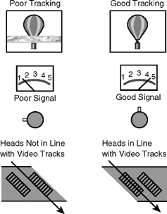
You can tell if a VCR is tracking properly simply by looking at the picture on a monitor. If the tracking is correct, the picture will be clear and stable. If the tracking is not correct, the picture will contain a large band of noise running through it. This band of noise indicates that the heads are not in proper alignment with the video information tracks.
Instead of using control track pulses, DV- and DVCAM-format tapes record pilot tones in one of the tape’s data tracks. These pilot tones automatically regulate the speed of the capstan during playback. DVCPRO tapes contain an additional track for control track.
VIDEOTAPE
RECORDING FORMATS
Since the introduction of videotape recording, approximately 50 different videotape formats have been introduced with varying degrees of success in the marketplace. (See Appendix 4.) You are familiar with terms like VHS and DV. These are different tape formats. A videotape’s format is described by a number of different factors:

Width of the Tape. Over the years tape width has been reduced from two inches to much smaller sizes (giving rise to the term small format videotapes). Today’s tape formats are ¼″(6.35mm), 8mm (Digital 8), or ½″ wide. (See Figure 5.4.)
Configuration of the Tape. Is it open reel or cassette? All modern videotape recorders use videocassettes.
Tape Speed. How fast does the tape run? In the DV tape formats, MiniDV tapes run at a slower speed than DVCAM tapes, which also run at a slower speed than DVCPRO tapes. Higher tape speed generally translates into higher recording quality.
How the Color Information Is Processed. Is it composite, S-video, or component? These terms will be described in more detail later.
How the Signal Is Recorded. Is it analog or digital?
How the Various Tracks of Information Are Arranged on the Tape. Four different sets of signals are typically recorded onto videotape: the video signal, the audio signal, control track, and SMPTE time code and/or data tracks.
Location of Signals on Videotape
All videotapes contain the following tracks of information: the video track, control track, and one or more audio tracks. In addition, some videotape formats also include a special cue or address track for SMPTE time code, and some of the digital formats include data tracks (called insert and track information [ITI] in the DV/DVCAM/DVCPRO system). The placement of these tracks of information varies from one tape format to another.
The Video Track. Video information is always centrally located on the tape, and the tracks of video information occupy most of the tape surface. Differences in formats are found in the width of the tracks of video information and the angle at which the tracks lie on the tape. In addition, formats differ with respect to the number of video tracks used to record each frame of information. For example, in analog formats like VHS/S-VHS, and Hi8, each video track contains one field of video information, and two tracks constitute a frame. In the DV/DVCAM/DVCPRO formats, the digital signal recording process is more complex, and 10 individual video tracks are needed to record each frame of the picture. (See Figures 5.5 and 5.6.)
The Control Track. Control track information in analog formats is recorded at or near the edge of the videotape by a stationary control track head. Edge recording presents a problem because the tape edge sometimes wrinkles in the machine. If the tape sustains any damage to the edge and the damage extends into the area where the control track has been recorded, the tape may be unstable when played. In the DV formats, only DVCPRO records control track; DV and DVCAM use pilot tones in one of the data tracks to control the rotating heads during tape playback.
Audio Tracks. Audio information can be recorded in three ways, depending on the tape format: one or more stationary audio heads can record sound in the longitudinal audio track(s), rotary heads can record analog high-fidelity audio along with the video information in the video tracks, or rotary heads can record digital audio.
The Cue or Address Track. Some analog tape formats contain an additional cue or address track that is used to record a longitudinal audio track or SMPTE (Society of Motion Picture and Television Engineers) time code information. Time code information provides an accurate identification code for each frame of video information and is widely used for logging tapes and in video editing. This is discussed in greater detail in Chapter 10.
Data Tracks. Digital tape formats may make use of one or more data tracks. For example, in the DV/DVCAM/DVCPRO formats, a special subcode track area contains SMPTE time code information, and a separate ITI area contains additional information about the track (e.g., whether it is consumer DV or DVCPRO) as well as the pilot tones that control DV and DVCAM playback.
VHS and DV Track Layouts
Two of the most widely used videotape recording formats are VHS and DV. VHS (the letters stand for “Video Home System”) is a ½″ analog, consumer-quality tape format. DV (the letters stand for “Digital Videocassette”) is a ¼″(6.35mm) digital videotape format that is used in consumer and professional applications. There are three general variants of the format: DV (or MiniDV), DVCAM (manufactured by Sony), and DVCPRO (manufactured by Panasonic). In order to illustrate some of the major similarities and differences between various tape formats, we will briefly discuss the track layout for these two tape formats.
VHS Track Layout. As you can see in Figure 5.5, the largest area of the tape contains the video information. Each track of video information is laid down at an angle on the tape. The top edge of the tape contains two analog audio tracks and the bottom edge of the tape contains the control track.
The relationship of the control track pulses to the video tracks is very precise. Note that there is one control track pulse for each track of video information on the tape, and as we discussed in Chapter 4, each video track contains one field of information, and two tracks of information constitute one video frame. (See Figure 5.5.)
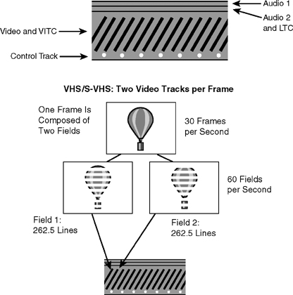
FIGURE 5.5 VHS Track Pattern
On VHS format tapes, SMPTE time code can be recorded in two places: linear time code, or LTC (pronounced “litsee”), can be recorded in one of the two audio tracks, and vertical interval time code, or VITC (pronounced “vitsee”), can be recorded along with the video information. Time code is discussed in greater detail in Chapter 10.
DV/DVCAM/DVCPRO Track Layout. As is the case for all videotape formats, in the DV/DVCAM/DVCPRO formats the video information occupies most of the central area of the tape. However, because the digital video signal is more complex than analog recording, each frame of video information is broken down into 10 sections of approximately 52 lines each, which are then recorded into 10 separate video tracks on the tape. (See Figure 5.6.) Digital audio can be recorded as two high-quality tracks, or four lesser-quality tracks. There is also a dedicated data track for insert and track information (ITI). DVCPRO tapes contain an additional track for control track.

FIGURE 5.6 DV/DVCAM/DVCPRO Track Pattern
Composite and Component Recording
The color video signal can be processed and recorded onto videotape in a number of different ways.
Composite Recording. Analog recording systems such as VHS record a composite, NTSC-encoded video signal. Each track of video information on the tape (the equivalent of one field of video information) contains the luminance (Y) and chrominance (C) parts of the signal mixed together with all the synchronizing information: color burst and horizontal and vertical sync. The output on VCRs and DVD players labeled “Video Out” is a composite video output. (See CP-5.)
Y/C Signal Processing (S-Video). Another term used to describe the way in which the video signal may be processed within a VCR is Y/C signal processing. In the Hi8 and S-VHS formats, luminance (Y) and chrominance (C) channels of information are processed separately within the VCR in order to achieve better color purity and image detail than is possible in conventional composite recording systems.
When the video signal is sent out of the VCR from the S-Video output and is displayed on a video monitor equipped with an S-Video input, luminance and chrominance travel as two separate signals. This produces a better-quality image than a conventional composite recording. (See CP-6.)
Component Recording. The highest-quality color recordings are made in systems that record the signal through the color difference process. This is often simply referred to as component recording. All of the new videotape recording formats developed in the past 10 years use the component recording process.
Like the S-Video process described earlier, the luminance signal (Y) is processed and recorded separately from the color components. However, in component recording, the process is carried further, resulting in a recording composed of the luminance signal (Y) and two color difference signals: red minus luminance (R – Y) and blue minus luminance (B – Y). Because the composition of the luminance channel is based on a fixed formula (Y = 30% red, 59% green, and 11% blue), there is no need to create the green minus luminance (G – Y) component because it can be reconstructed from the other three signals.
By processing and recording the luminance and chrominance signals separately on the videotape, component VCRs produce pictures with superior picture quality—the images are sharper (a function of processing the luminance signal independently) and the colors are purer than those obtained in composite or Y/C recordings.
In analog component recording systems (e.g., Betacam SP), the color components are referred to as R – Y and B – Y. In digital systems (e.g., DV, DVCAM, and DVCPRO), the color components are Cr and Cb. In both systems, the luminance signal is Y. (See CP-6.)
One drawback of component processing and recording is that the component signal is incompatible with conventional video distribution and display equipment and requires special monitors and processing equipment. Although they record a component signal, consumer DV-format VCRs and camcorders have both S-Video and standard NTSC composite video outputs, which allow the tapes to be dubbed to conventional VCRs and viewed on conventional video monitors.
Analog Recording
Another difference in the way in which the video signal is processed and recorded is reflected in whether the signal is analog or digital. An analog signal is one in which the recorded signal (audio or video) varies continuously in relation to the sound or light that produced it. The electrical video signal produced through the analog process, for example, varies in direct proportion to the light entering the camera lens, and the video waveform that is produced is continuous. When that signal is stored on videotape, the electrical signal is stored as a continuous variation in voltage as well.
Digital Recording
In the digital recording process, the incoming analog signal (audio or video) is converted into a digital signal composed of a series of on/off pulses, or bits. The conversion occurs first by sampling various points of the signal and then by converting that information into a numerical code for storage and replay. When the signal is replayed, the process is reversed and the digital information is converted back to an analog representation of the appropriate sound or picture. There are three steps to the process: sampling, quantization, and compression.
Sampling. The sampling rate describes how often the elements of the analog signal are converted into packets of digital information. Sampling rates for video vary greatly, depending, for example, on whether the signal is standard-definition television (SDTV = 13.5Mhz) or high-definition television (HDTV = approximately 74Mhz). That is equivalent to 13.5 million samples per second for SDTV and 74 million samples per second for HDTV.
In addition to the overall sampling rate, the color sampling rate describes how often the luminance and chrominance elements of the analog video signal are sampled for conversion into packets of digital information. Three sampling rates are used in digital video—4:2:2, 4:1:1, and 4:2:0. (See Figure 5.7.)
In 4:2:2 sampling, each pixel in each line of video is sampled for luminance information (Y), whereas the chrominance values (Cr and Cb) are sampled only for every other pixel. Thus, in a string of four pixels there will be four luminance samples (one for each pixel) and two each of the chrominance samples.

In 4:1:1 sampling, the luminance sampling rate is the same, but chrominance is sampled only once, instead of twice, for each set of four pixels.
In 4:2:0 sampling, luminance is again sampled for each pixel. However, the Cr color component is sampled at every other pixel only in the odd-numbered scan lines, while the Cb color component is sampled at every other pixel only in the even-numbered scan lines.
The first, 4:2:2 sampling, provides the highest-quality signals and is therefore the standard for broadcast and HDTV. The second, 4:1:1 sampling, is used in the DV, DVCAM, and DVCPRO formats. 4:2:0 sampling is used in DVDs and the HDV tape format.
Quantization. As the signal is sampled, it is converted into packets of digital information (quantization). However, the amount of data this process produces is immense, and to make it easier to store and transmit the information, compression is used.
Compression. Compression refers to the reduction in size of a digital data file or a stream of digital information. There are two types of compression: lossless compression and lossy compression. Lossless compression works by compressing a file without removing any data. Lossy compression, the most popular method of compression, works by eliminating repetitive or redundant information.
For example, imagine a video shot in which the camera is held still as an automobile drives into the frame and toward the camera. In each frame the foreground and background information (trees, street, houses, etc.) remains the same. What changes is the position of the car in the frame and its relative size as it gets closer to the camera. When the video signal is compressed, the background information is encoded once for the entire sequence of frames in which the car appears, but the car needs to be encoded continuously for each frame in which it appears, in order to capture its movement.
Compression is expressed as a ratio; higher numbers indicate greater compression, and lower numbers indicate lesser compression. So you can see that the 5:1 compression ratio used in the DV formats is higher than the approximately 3:1 compression ratio used in Digital-S. Signals recorded with less compression generally produce better pictures than those recorded with more compression.
Compression Methods. Several different compression methods are widely used in video systems:
JPEG (Joint Photographic Experts Group) compression was originally designed for use in digital still photography but has been adapted for use with video (motion JPEG).
MPEG-1 (Motion Picture Experts Group) compression is designed for use in CD-ROMs.
MPEG-2 is the standard for broadcast television and DVDs.
MPEG-3, more popularly known as MP3, is widely used to compress audio files.
MPEG-4 is used in a range of applications including digital television and streaming media on the Internet.
Digital Advantages. Although the digital signal is significantly more complex than the analog signal, it has several distinct advantages over analog recording. Digital signals can be recorded, replayed, and copied with greater accuracy and less “noise” than analog signals. This makes it possible to create clean copies across generations of tape. A copy made from a copy of the original should be indistinguishable from the original if all copies are made digitally. A third-generation copy of an analog tape will show noticeable degradation of picture quality. Digital signals are also preferable to analog ones because they can be processed by a computer and manipulated to create stunning visual effects.
Digital Videotape Formats
All of the videotape formats introduced since 1993 record the video signal digitally. A variety of digital tape formats are marketed to professional and consumer users. (See Figure 5.8.)

FIGURE 5.8 Digital Videocassette-Format Camcorders
Digital Videocassette (DV). DV is one of the newest and smallest digital tape formats. DV systems record up to four digital audio tracks and a digital component video signal on a small 6.35mm (¼″) cassette.
Image and sound quality rival the professional analog Betacam SP format, which was the broadcast standard before the current generation of digital tape formats was introduced. There are five variants of the DV format:
1. DV (Digital Video) was originally targeted at the consumer market, but found ready acceptance in the professional market because of its high quality and low cost. The first generation of DV equipment exclusively used a very small cassette (MiniDV) as does most DV equipment sold today. However, several manufacturers now offer a professional DV camcorder that can record either to a MiniDV cassette or to a standard DV cassette.
2. DVCAM is manufactured by Sony and is targeted at industrial and professional users.
3. DVCPRO (D7) was developed by Panasonic and BTS/Philips and is targeted at the professional and broadcast market. It has found wide use in ENG applications.
4. DVCPRO 50 is a modified version of DVCPRO that features 4:2:2 sampling instead of the 4:1:1 rate characteristic of the other DV formats. DVCPRO 50 records twice as much data as conventional DVCPRO, making it suitable for High-Definition as well as Standard- Definition digital recording.
5. DVCPRO-HD is yet another modified version of DVCPRO designed by Panasonic for both 1080i (interlaced scanning) and 720p (progressive scanning) High-Definition as well as Standard-Definition digital recording. DVCPRO-HD records at twice the data rate of DVCPRO 50 (100 megabits/second versus 50 megabits/second), with a compression ratio of 6.7:1, versus 3.3:1 for DVCPRO 50 and 5:1 for DVCPRO.
Major differences between the variants of the DV format include the width of the video tracks (10 microns for DV, 15 microns for DVCAM, and 18 microns for DVCPRO), tape speed (DVCAM and DVCPRO run at higher speeds than DV), and the type of videotape used (DV and DVCAM record on metal evaporated tape; DVCPRO uses metal particle tape). As a result of these differences, not all of the variants are compatible with each other: while DV tapes will play back in DVCAM and DVCPRO equipment, neither DVCPRO nor DVCAM tapes can be played back in DV machines, and you can’t record onto a DV (MiniDV) tape in either a DVCAM or DVCPRO machine.
Tape-to-tape editing can be done in the DV formats using portable laptop editing systems (see Figure 5.9). On equipment with a FireWire connector (a standardized six-pin connector developed by Apple Computer carrying digital video, audio, and time code), VCR output can be connected directly to a personal computer for digital desktop video production.
HDV. JVC, Sony, Canon, and other manufacturers have all been actively involved in developing relatively inexpensive (under $10,000) camcorders that record a high-definition signal onto MiniDV cassettes. The HDV format has a resolution of 1,280 pixels by 720 lines in the 16:9 screen format. MPEG-2 compression is used to compress the data for recording. The HDV format was developed in 2003, but it was not until 2005 that JVC and Sony introduced three-chip camcorders that took advantage of it. (JVC had previously introduced a single-chip camcorder in 2003.) Sony’s Z1U HDV camcorder uses the 1080i (interlaced) 30 fps standard, while JVC’s GY-HD100U uses the 720p (progressive) standard, running at either 24 or 30 fps, noninterlaced. (See Figure 5.10.)

FIGURE 5.9 Portable Video Laptop Editing Systems

Panasonic has eschewed the use of the MiniDV format for high-definition recording, choosing to focus instead on DVCPRO tape to record the high-definition signal (DVCPRO-HD), or by using its P2 memory cards as recording media. (These are discussed later in this chapter.)
Digital 8. Introduced by Sony in 1999, Digital 8 records a digital component signal that is the same as DV, except that it is recorded onto 8mm tape instead of 6.35mm tape. Analog Hi8 tapes can be played back in Digital 8 camcorders and VCRs. This format is targeted principally at the consumer market.
Digital-S (D-9). Developed by JVC for the professional production market, Digital-S records a component digital video signal and four audio channels onto ½″ metal particle tape. Some VCRs contain a “preread” feature that can play back and simultaneously record new information, making it possible to create multiple layers of images for special effects and transitions without the use of an editing system or video switcher.
Digital Betacam and Betacam SX. Developed by Sony, Digital Betacam records an extremely high-quality component digital signal with four digital audio tracks onto ½″ tape. Betacam SX is a lower-cost digital component ½″ format targeted at ENG users.
D-3, D-5, and HD-D5. D-3 (composite) and D-5 (component) digital VCRs were developed by Panasonic. Like most of the other formats, they use a ½″ cassette tape. HD-D5, a high-definition version of the D-5 format, is one of the principal formats used for recording HDTV in the 1080i or 720p variants.
D-VHS. JVC’s D-VHS (digital VHS) is designed for off-air recording of digital television broadcasts. It uses ½″ tape, and analog VHS and S-VHS can be played back in the D-VHS machine. Quality is slightly better than what can be achieved with a DVD.
Analog Videotape Formats
Analog videotape formats are fast disappearing from the marketplace. However, a few formats are still in use:
VHS. VHS (video home system) emerged as the dominant format for home video recording in the early 1980s, and until the introduction of DVDs, also served as the dominant medium for the rental movie market. VHS is strictly a consumer format, and is generally not suitable for professional production applications.
S-VHS. S-VHS (Super-VHS) was introduced by Victor Company of Japan (JVC) in 1987 and marketed to industrial and professional users as a low-cost alternative to Sony’s professional Betacam format. S-VHS systems produced improved resolution and color quality in relation to VHS systems, but they are vastly inferior to DV.
Hi8. Hi8 format equipment was introduced by Sony in 1989 to replace conventional 8mm video equipment, and found a niche in the consumer and prosumer markets because of its low cost, extreme portability, and high-quality first-generation recordings. Despite its past popularity, Hi8 has been displaced from the marketplace by the Digital 8 and DV digital tape formats.
Betacam SP. Betacam SP, developed by Sony, is a professional, broadcast-quality ½″ analog component recording format. Betacam SP was the de facto standard for field recording in ENG and EFP in professional broadcast operations in the United States until the late 1990s, when it was supplanted by a variety of digital videotape formats. Sony stopped manufacturing Betacam SP equipment in November 2001, although many Betacam camcorders and VCRs remain in use today.
COMPATIBILITY
Upward and Downward Compatibility
Compatibility refers to the capability of a given VCR to play back a particular videotape. If a videotape can be played back on a VCR, the two are compatible; if it cannot be played back, the two are incompatible. Compatibility is determined by the format of the videotape recording and the playback machine. Tapes recorded on any MiniDV VCR should be compatible with all other MiniDV VCRs. Similarly, any VHS tape should play back on any other VHS machine. However, remember that a tape must be played back at the same speed at which it was recorded. A MiniDV tape recorded in the 90-minute LP mode will not play back on a machine equipped with only the 60-minute SP playback mode.
The terms upward compatibility and downward compatibility are used to describe compatibility issues that arise between conventional tape formats and their improved-performance successors. For example, conventional ½″ VHS was modified to create a higher-resolution Super-VHS tape format. Conventional VHS recordings can be played back in S-VHS machines; thus, they are upwardly compatible. However, S-VHS tapes cannot be played back in conventional VHS machines; thus, we can say that S-VHS is not downwardly compatible with conventional VHS. MiniDV tapes are upwardly compatible with DVCAM and DVCPRO, and DVCAM is upwardly compatible with DVCPRO (DV →DVCAM →DVCPRO). However, while DVCPRO is downwardly compatible with the newest generation of DVCAM machines, neither DVCAM nor DVCPRO can be played back in DV (MiniDV) equipment.
Dubbing
What, then, do you do if you have a tape in one format but have a machine in another, incompatible format? The answer is to make a dub. A dub is simply a copy of a tape. Because all VCRs have a series of standard video and audio inputs and outputs, it is possible to take a tape in one format and make a copy of it in another format. For example, you can dub a DV tape to VHS, DVCAM to DVCPRO or vice versa, and so on. To make a dub, you need the original tape and a machine capable of playing it back. In addition, you need another machine in the format you want to dub to, and a blank tape. Put the original tape into the machine that will play it back, and connect the video and audio outputs of that machine to the video and audio inputs of the other machine. The machine with the original tape in it is called the source VCR, and the machine on which the information will be rerecorded is the record VCR.
Through the process of dubbing, copies of any tape can be made in any other format. However, in the analog tape formats there is always some quality loss in the copy. This quality loss appears first as noise in the video picture. The copy may appear a little grainy and fuzzy. If a copy is made of the copy, the signal will continue to degrade, losing definition and color values. The further away from the original your copy is, the poorer the quality of the tape.
The original tape is referred to as a first-generation tape. The first copy made from the original is a second-generation tape; a copy made of the second-generation tape is a third-generation tape; and so on. VHS systems are capable of producing good-quality copies only up to the second, and sometimes the third, generation. After that, the quality of the signal becomes noticeably poorer, and by the fourth or fifth generation, even the color of the original may be unrecognizable. Green faces and red grass hint at how many generations away from the original the copy may be.
Digital video VCRs that have digital video inputs and outputs (e.g., a FireWire connector) allow the signals to be transferred from one VCR to another with little or no noticeable loss in quality.
TYPES OF VIDEOCASSETTE
RECORDERS
VCRs can be described by the functions they perform. In addition to camcorders and portable VCRs (described in Chapter 3), there are three other kinds of VCRs: video players, video player-recorders, and editing VCRs.
Video Players
Video players are VCRs incapable of recording—they can be used only to play back a videotape. The principal reason for buying a playback-only VCR lies in its cost. They are considerably cheaper than player-recorders because they do not contain the extra circuitry that makes recording possible.
Video Player-Recorders
Probably the most common type of VCR is the video player-recorder (see Figure 5.11). Any VCR with the capability to record and play back a videotape is a player-recorder. These machines are extremely versatile. They can record signals from video cameras and other VCRs. If they are equipped with a television tuner—the device that picks up broadcast or cablecast television signals—they can also record programs off the air or cable.

Editing Videocassette Recorders
The third type of machine is the editing VCR. It is equipped with special electronic circuitry that enables it to edit the video signal. We will discuss how this works in considerable detail in Chapter 11.
VIDEOTAPE
The storage medium employed in most camcorders and VCRs is videotape. Videotape is simply a very thin strip of plastic (polyester or Mylar) that is coated with metal oxide particles. The picture and sound received by the camera and microphone are generated in the form of electrical impulses. These electrical impulses are directed to the videotape, where they are stored magnetically. A series of video and audio heads, which in effect are very small electromagnets, magnetize the metal particles (usually iron oxide or chromium dioxide) on the tape in a pattern that corresponds to the electrical input signals. Once these particles have been magnetized by the heads in the correct pattern, the signal is safely stored on the tape. Playback of the stored signal simply reverses the process. As the tape is played back, the video and audio heads read the information recorded on the tape. If the VCR is connected to a monitor, you see the image and hear the sound.
Improvements in tape quality have been a significant factor in the development of recording formats with enhanced detail and color qualities. Two types of videotape are widely used: The metal evaporated tape (ME) used in Hi8 and consumer DV recording systems is fragile and, at least with respect to Hi8, has earned a bad reputation for having a lot of dropouts. The metal particle tape (MP) used in many of the digital formats is more durable and less prone to dropouts (discussed later in this chapter).

Size
The size of a videotape refers to its width. Videotape comes in a number of different widths. The most common portable field production systems use tape that is either 6.35mm, 8mm, or ½″ wide (see Figures 5.4 and 5.12). The trend is toward smaller tape size for a number of reasons: it is more economical to use because it costs less money to produce; the machines used to record and play back the video signal can be made smaller because narrower- width tapes do not require the massive head drum assemblies that the older, large-format tapes required; and the tape is smaller and requires less space to store.
In many cases, due to improvements in the way in which the signal is recorded, smaller-format tapes provide better-quality recordings than do their larger-format predecessors. So the proliferation of formats should not be seen only as the difference between less expensive and more expensive systems, or between high-quality and poor-quality systems. In many ways, the development of these smaller-tape formats reflects significant advances in electronic technology. The move toward miniaturization in all other areas of electronic technology has also had a dramatic impact on the design of video gear.
DV-format cassettes come in three different sizes (see Figure 5.13 on page 142). The small MiniDV cassette, which holds an hour of material in the SP record mode (1½ hours in the LP mode), is used in DV camcorders. A medium cassette capable of a maximum of 30 minutes of recording is available for DVCAM and DVCPRO equipment, as is a large cassette in a variety of tape lengths ranging from 12 minutes to 3 hours. A mediumsized cassette adapter is used to play back MiniDV cassettes in full-size DVCPRO machines (see Figure 5.14 on page 142).

Configuration
The other important aspect of videotape is its configuration. Configuration refers to the physical design of the tape. Is it an open-reel tape, or is it a cassette? All of the contemporary formats use cassette tapes. The principal advantage to the use of a cassette tape is that the machine automatically threads the tape into the machine; reel-to-reel systems require that the tape be manually threaded into the machine.
If you are working with a portable video system, you are working with videotape in the cassette configuration. That is why you will find two different terms used to refer to video recorders. Some people call them videotape recorders, or VTRs, which simply indicates that videotape is used to record the video signal. Others will make a point of referring to their videocassette recorder, or VCR. Although VCR is more precise than VTR, the two terms are used interchangeably.

FIGURE 5.14 MiniDV Cassette Adapter
Record Safety Devices
All VCRs contain several erase heads. When a machine is put into the record mode, the erase heads engage and erase the previously recorded signal before the record heads pass over the tape to lay down the new signal. Because accidental erasure of material is something that everyone wants to avoid, all cassette tapes contain a record safety (see Figure 5.15). When the record safety device is engaged, it is impossible to record over the material on a tape. Depending on the tape format, the record safety may be a small plastic tab (VHS/S-VHS) or switch (DV/DVCAM/DVPRO) on the side of the tape housing. In each of these tape configurations, you can record when the record safety device is in place, but not if it has been removed or set.
Because information is stored on videotape as magnetic impulses, the videotapes can be used over and over. It is quite simple to erase an entire tape by exposing it to a bulk eraser, a powerful electromagnet that randomizes the arrangement of the particles on the tape, thus eliminating the recorded signal. A bulk eraser will erase a tape whether or not the record safety has been removed. Tapes can be bulk-erased, or bulked, simply by passing the tape over the surface of the bulk eraser. There is no way to prevent the bulk eraser from doing its job. The best protection against accidental bulk erasure of tapes is through correct, clear labeling of tapes. If you know what is on the tape and clearly mark it “DO NOT ERASE,” you stand a greater chance of preventing accidental erasure than if the tape does not carry such a warning. Finally, because any electromagnet can act as a bulk eraser, it pays to store tapes away from telephones, fan motors, and so on.

FIGURE 5.15 Videocassette Record Safety Devices
Care of Videotape
Videotape should be handled and stored with care. The surface of the tape can easily be damaged, so videotape should never be touched with bare hands. Fingers leave an oily deposit that can damage the tape. If you must touch the tape, wear cotton gloves.
Videotape should be stored under conditions similar to those comfortable for people. Temperature should not vary excessively, as extreme heat and cold will damage the tape. Similarly, extreme humidity can cause great problems by making the tape sticky. This may cause it to bind together within the cassette or cause excessive friction against the head drum of the VCR, making tape playback and recording impossible.
Protection from dust and smoke is also important. Both of these elements can seriously damage the recording surface of the tape as well as the video heads within the VCR.
Videotapes should be stored on end, rather than on their side. Do not lay them down flat and stack them up one on top of another; instead, stand them up side by side. Also make sure that tapes are wound to the beginning or end of the spools for storage.

FIGURE 5.16 Video Head Clog
Dropouts
Videotape begins to wear out as it gets old. One sign of wear is the dropping out of information in the picture. Dropouts occur when parts of the magnetic coating that hold the signal information fall off the tape, leaving a hole in the picture. These can easily be seen on a monitor, where they appear as small black specks in the picture. Tape with a lot of dropouts should be discarded. Excessive dropouts not only affect the picture quality but may also affect picture stability and sound quality.
Many high-quality VCRs contain dropout compensators. A dropout compensator detects the loss of information caused by tape dropouts and corrects the problem by replacing the lost information with the line of information that immediately preceded it.
Excessive dropouts can cause the video heads to clog (see Figure 5.16). If there is head clog, the heads do not record or play back, and need to be cleaned. The VCR heads may become clogged if the videotape is old or if the VCR is left in the pause mode for an excessive period. If the latter happens, the heads are in continual contact with one spot on the tape. This tends to damage the tape by wearing off the magnetic particles at that point, leaving a blank spot that will no longer hold signal information.
Cleaning the Heads
As the video heads come in constant contact with videotape during record and playback, they tend to get clogged with oxide particles that drop off the tape. Consequently, the heads must be cleaned regularly to guarantee high-quality signal recording and playback.
You can tell when the video heads are getting dirty simply by looking at the picture produced by the VCR on a monitor. Clean heads produce a clear, sharp picture. When the heads are dirty, the picture looks fuzzy or noisy. In the digital tape formats, the image may begin to pixillate (look “blocky”) or the motion may freeze up. In extreme cases, the heads become completely clogged, and the machine may fail to play back or record anything.
Heads should therefore be cleaned regularly, depending on use. If you use your VCR infrequently, you may need to clean the heads only every month or two. If you use the machine heavily, or if you are using old tape stock, you will certainly need to clean them more often—perhaps weekly, if not daily.
Many video service centers provide a head-cleaning service, or you may have technical staff on hand who can perform the job. The heads may be cleaned by applying commercially available head-cleaning fluid to the video heads, head drum, and pinch rollers and guides within the VCR, or by using a wet or dry head-cleaning cassette. Be sure to follow the manufacturer’s guidelines in choosing the appropriate head-cleaning method so you do not damage the delicate head assembly or void the equipment warranty.
TAPELESS VIDEO
RECORDING DEVICES
Although videotape has been the principal medium for recording the electronic video signal for almost 50 years, new technologies are evolving that will ultimately replace videotape as the recording medium of choice. A number of these new technologies are in use now.
Computer Hard Disks and Video Servers
A hard disk is a magnetic storage system most widely used in computers. Information is stored on a series of round, magnetic platters within the computer. Video servers are computers equipped with hard disk storage systems that can record and play back video. In editing applications, servers are often used to store video footage in a central location, which can then be accessed from individual editing workstations. In broadcast and cable stations, video servers are increasingly used in place of VCRs to store commercials and programs. When the server is connected to the central computer, which contains the day’s program log, commercials and programs can be replayed automatically.
Over the years several manufacturers have developed hard disk-based camcorder recording systems. Ikegami and Avid introduced a hard disk camcorder as early as 1995 and now market a High-Definition “Editcam” camcorder with a built-in digital disk recorder. JVC is marketing a dockable hard disk drive recorder that functions with various JVC professional camcorders. (See Figure 5.17.) Several other manufacturers make portable hard disk systems that can be connected to a digital camcorder via its FireWire port.
When field shooting is complete, the disk drive is removed from the camcorder and connected directly to a compatible nonlinear editing system via its FireWire connection. This eliminates the need to capture (transfer) the digital files from a videotape. Video clips can be moved directly into the nonlinear editing system’s time line, and editing can begin immediately.

FIGURE 5.17 JVC Hard Disk Drive Camcorder
Optical Discs
CDs and DVDs are two examples of relatively inexpensive optical disc playback and (in some cases) recording systems. A laser within these systems is used to write (record) and read (play back) program information. Because no recording heads touch the discs, they are much more reliable than tape-based systems. They also have the added advantage, similar to the hard disk systems already described, of allowing random access to information anywhere on the disc.
DVD. Because of their limited storage capacity, CDs are not widely used to store video program information, but DVDs are. DVDs (digital versatile discs) have the capacity to record up to 17 gigabytes of data, but most DVD formats in the consumer market today hold 4.8 gigabytes. This is equivalent to approximately two hours of high-quality video, making DVDs a good choice for the distribution of video program material and feature-length movies.
DVDCAM. The first manufacturer to capitalize on DVD technology for use in a camcorder was Hitachi, which in 2001 introduced a digital camcorder that recorded full-motion MPEG-2 video onto a DVD-RAM disc. (See Figure 5.18.) The system is capable of recording 30 minutes of high-quality (704 × 480) video on each side of the DVD disc. Hitachi has been joined in the marketplace by Sony, Panasonic, and Canon, which also market their mini DVD camcorders to the consumer market. None of these camcorders is designed to meet professional production specifications.
Sony XDCAM. Sony introduced its professional XDCAM in 2003 at the National Association of Broadcasters annual convention in Las Vegas. XDCAM is a professional optical disc camcorder that is capable of recording in either the DVCAM format or in MPEG-2. Each single-sided disc has a storage capacity of 23.3GB, records 85 minutes of DVCAM video or 45 minutes of MPEG-2, and costs about $30. (See Figure 5.19.)
HD-DVD. The next generation of DVD technology will most likely see the development HD-DVD, which stands for “high-definition” or “high-density DVD.” These systems will use “blu ray” technology (a blue laser with a wavelength as short as 400 nanometers) and will be able to store several more times the information than the current versions are capable of storing.

FIGURE 5.18 Hitachi DVDCAM Camcorder

Memory Cards
Memory cards use silicon chips instead of magnetic media to store data. Sometimes also called flash memory, they have the added advantage of retaining the data even when the power is turned off. Memory cards have become quite popular as the storage device of choice in digital still cameras: CompactFlash, SmartMedia, and Memory Stick are some examples.
Panasonic has adapted memory card technology for use in its P2 professional camcorders, introduced at the 2004 NAB convention. (See Figure 5.20.) Panasonic touts this system as “having no moving parts,” unlike hard disk and optical disc systems in which motors rotate the disks at extremely high speeds.
P2 camcorders hold up to five memory cards. 4GB and 8GB P2 cards are currently available at a cost of approximately $200/GB of storage. Storage rates are 1 GB/minute for DVCPRO-HD, 2 GB/minute for DVCPRO 50, and 4 GB/minute for DV/DVCPRO 25. Panasonic projects the development of cards storing up to 128GB, which would hold 144 minutes of DVCPRO-HD, 285 minutes of DVCPRO 50, or 576 minutes of DV/DVCPRO program material. But the success of this system will be heavily dependent on reducing the cost of the memory media.
With the exception of the videotape used in camcorders for field acquisition of program material, many production facilities today are “tapeless,” relying on disk-based digital nonlinear editors for video editing, and video servers for storage. The development of professional hard disk, optical disc, and flash memory cards as camcorder storage media marks a significant moment in the transition to an entirely tapeless production environment.

FIGURE 5.20 Panasonic P-2 Recording Systems
SIGNAL
PROCESSING
Whenever a video signal is recorded, a certain amount of signal degradation takes place. Both the stability and the quality of the signal (how the picture looks) may be affected. For these and other reasons, several different kinds of signal-processing devices are routinely used during postproduction. The most common types of signal-processing units include time base correctors, video-processing amplifiers, and dropout compensators.
Time Base Correctors
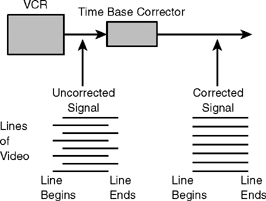
A time base corrector (TBC) is used to correct timing errors in the signal that is played back from the videotape recorder. All VCRs introduce errors into the time base of recorded material. The time base refers to the rate at which individual lines, fields, and frames of video information are reproduced. As you know from the earlier discussion, each of these components of the video signal should take place in a precise amount of time: a line lasts 63.4 microseconds, a field has a duration of 1/60 of a second, and a frame lasts 1/30 of a second. Deviations from this model are called deviations in the time base of the signal. Portable VCRs are notorious for producing a video signal that deviates from the standard.
The function of the time base corrector is to correct the video signal with respect to timing. The VCR’s output is fed into the time base corrector, where it is digitized, analyzed, and corrected. The time base corrector’s output is a broadcast-quality signal in terms of its timing.
A time base corrector must be used in conjunction with any VCR if you plan to broadcast a tape. Similarly, if you want to transfer the material from one tape format to another, the VCR output should first be processed through a time base corrector to guarantee the ultimate stability of the dub. A time base corrector must also be used if the output from a VCR is going to be connected to a video switcher.
The time base corrector stabilizes the video signal from the VCR(s) and synchronizes it with the other video sources in the system. This is done by routing the VCR’s output signal into the time base corrector, which converts it into a digital signal and stores it line-by-line. Then, the time base corrector compares the horizontal sync pulses from the sync generator with the sync pulses on the tape. It brings the tape into sync with the standard established by the sync generator by reading out each line of information at the correct time. This ensures that each line of video coming from the VCR through the time base corrector begins and ends in time with the horizontal sync pulses supplied by the sync generator (see Figure 5.21).
Time base correctors are often described with respect to their window, which indicates how much information a time base corrector is able to store at a given time. Most modern time base correctors can store a full frame of information. They are called full-frame time base correctors, or frame synchronizers.
Processing Amplifiers
Time base correctors are commonly used to improve playback signal stability; improvements in signal quality are made with a video processing amplifier, or proc amp. Proc amps, or color correctors as they are sometimes called, are used to correct both the quality of the color in the signal and the quality of the sync and color burst signals. With a proc amp, adjustments can be made in the overall video level (gain) and setup level (pedestal), as well as in the quality of the color itself in terms of luminance, hue, and saturation.
As with time base correctors, there are limits to the amount of color correction possible with a proc amp. If the signal was originally recorded with gross errors resulting from camera malfunction or some other severe problems, the proc amp may not help.
Dropout Compensators
Another common type of signal processing equipment is the dropout compensator (DOC). The dropout compensator is used to correct signal-quality problems caused by the loss of particles of the magnetic coating from the surface of the tape. When dropouts are detected in a line of video information, information from the previous line is repeated to fill in the hole. Dropout compensators are frequently built into other video components. For example, time base correctors frequently have built-in dropout compensators, as do many VCRs.