This chapter will discuss electromagnetic waves, with a focus on light and its applications. The ideas contained in this chapter should help you understand the basics behind optical storage of information, that is, compact discs (CDs), fiber optics used in telecommunications, as well as a host of other devices that use light.
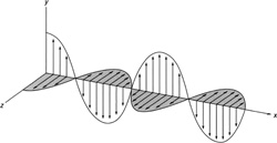
FIGURE 16.1 Light is a wave made of electric and magnetic fields that oscillate perpendicular to the direction of travel.
16.1 ELECTROMAGNETIC WAVES
Electromagnetic waves are different than water and sound waves because they can travel through a vacuum, that is, they need no medium in which to travel through. Electromagnetic waves are made of electric and magnetic fields that change with time and oscillate perpendicular to the direction of travel (Figure 16.1).
The electromagnetic spectrum consists of all the electromagnetic waves of various frequencies (Figure 16.2). If the electromagnetic fields oscillate in the right frequency range, we can see them. Light is just part of a whole spectrum of electromagnetic waves. At other frequencies they may be radio waves, X-rays, microwaves, and so on.
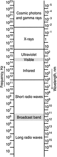
FIGURE 16.2 The electromagnetic spectrum.
16.2 THE VISIBLE SPECTRUM
The visible spectrum is the part of the spectrum that we can see. Different colored lights correspond to different wavelengths of light.
16.2.1 White Light
White light is light composed of many different colors (Figure 16.3). The colors can be separated out using a prism.
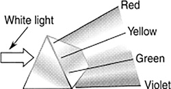
FIGURE 16.3 White light is composed of many different colors.
16.2.2 Colors
In order to see an object, light must be reflected off it. If you shine white light on an object and all the colors that compose the white light are absorbed except, for example, green, the object will appear green. Paints are essentially color absorbers. The color of the paint is the color from white light that does not get absorbed (Figure 16.4).
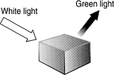
FIGURE 16.4 The color of an object is the result of the color of the white light shining on the object that does not get absorbed.
16.2.3 Infrared
At wavelengths slightly longer than visible light lies the infrared part of the spectrum. Infrared radiation is otherwise known as thermal radiation or radiant heat (Figure 16.5).
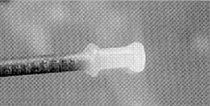
FIGURE 16.5 The infrared part of the spectrum is associated with the transfer of heat.
16.2.4 Ultraviolet
At wavelengths slightly shorter than visible light lies the ultraviolet part of the spectrum. Ultraviolet rays, or UV rays, cause sunburn. Welders wear goggles to protect their eyes from UV rays (Figure 16.6).

FIGURE 16.6 Large amounts of UV light are produced in welding or cutting metals.
16.3 GENERATION OF ELECTROMAGNETIC WAVES
Electromagnetic waves can be generated in different ways to create specific regions of the electromagnetic spectrum.
16.3.1 Radio Waves
Wiggling an electric charge will generate radio waves. To understand this better, consider an electron with its electric radial field lines emanating from it. If a charge is wiggled up and down, these lines will be moved up and down, similar to a jump rope being snapped, generating a wave traveling down a rope (Figure 16.7). Like the jump rope, the electromagnetic wave will be transverse, but unlike the jump rope, no medium is needed for the wave to travel on. Accompanying this wave will also be a magnetic field (this will be explained in the next chapter). The radio waves generated will have the same frequency as the frequency the electrons are wiggled at. A radio transmitter, along with its antenna, is effectively an electron wiggler.
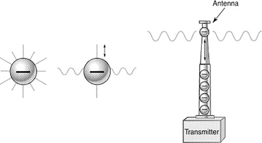
FIGURE 16.7 Wiggling a charge creates an electromagnetic wave. Radio transmitters wiggle electrons up and down in an antenna, producing electromagnetic waves.
16.3.2 Microwaves
Accelerating electrons in a circular path at a particular rate will generate microwaves. A magnetron is a device that generates microwaves using a magnet to accelerate a current of electrons into a circle, using a magnetic field (Figure 16.8). Accelerating electrons like this causes them to radiate electromagnetic waves in the microwave region of the spectrum. Every microwave oven contains a magnetron.
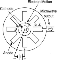
FIGURE 16.8 Generating microwaves using a magnetron.
16.4 LIGHT
Electromagnetic waves also can come from atoms. These waves are much shorter than radio waves. Orbiting every atom are electrons, some of which have more energy than others. If an atom is given energy, or excited, the electrons orbiting the atom begin jumping orbits. When an electron jumps from a high-energy orbit to a lower-energy orbit, the atom gives off an electromagnetic wave called a photon, or a packet of energy (Figure 16.9). The photon has a frequency, or color, related to the energy difference between the orbits. If the energy range between the two orbits is just right, visible light will come out. Sodium vapor lights illustrate this clearly. The photons coming out of sodium vapor as a result of the electrons jumping orbits correspond to a wavelength of 590 nm, or yellow light.
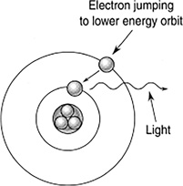
FIGURE 16.9 Light emitted from atoms results from electrons jumping from one energy orbit to a lower one.
Incandescent light bulbs generate light by heating the filament inside with an electric current. This heat energizes many different electrons in the filament in many different ways. Photons of various wavelengths will be produced, resulting in white light (Figure 16.10). Most incandescent light bulbs emit only 10% of their energy in the visible part of the spectrum.
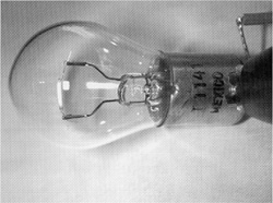
FIGURE 16.10 Light is produced in incandescent lamps by heating of the filament using an electric current. This heat is energizing so many electrons in so many different ways that the output is composed of many frequencies, or white light.
Fluorescent lights contain a low-pressure mercury vapor (Figure 16.11). At one end of the tube is a filament that is heated and at the other end is an electrode at a larger voltage, compared with the first. The hot filament “boils” off electrons and these are accelerated toward the high-voltage end, striking mercury atoms on route, which causes the mercury atom to excite, then de-excite, giving off UV light. The UV light then strikes a fluorescent coating on the inside of the tube, exciting these atoms, which, in turn, give off visible light. Fluorescent lights are much more energy efficient than incandescent light, putting out about 40% of their light in the visible part of the spectrum.
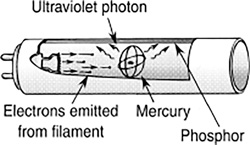
FIGURE 16.11 A fluorescent light.
16.4.1 Lasers
Laser light is different than light from a light bulb. Light from a light bulb is white light, that is, of many frequencies. A laser light contains one frequency; in other words, it is monochromatic (Figure 16.12).
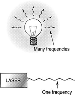
FIGURE 16.12 White light contains many frequencies. Laser light contains one frequency and so is monochromatic.
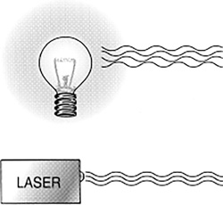
FIGURE 16.13 White light is incoherent. Laser light is coherent.
Light waves coming out of a light bulb are all out of sync with one another.
The waves are said to be incoherent. Laser light is coherent, so that all the waves of the light are in step with one another (Figure 16.13).
The mechanism by which gas lasers and solid-state lasers work is the same.
The process consists of the following steps:
Step 1: Electrons in their orbits around their atoms are excited to higher-energy orbits (Figure 16.14). Excitation can be done in various ways using light, electrical discharge, chemical reactions, and so on.
Step 2: Excited electrons begin to jump down to lower-energy orbits. The electrons spend different amounts of time in the various orbits before jumping to the next lower orbit. If the electrons spend a lot of time in one particular orbit, soon there will be a buildup of electrons there. This is called population inversion because a large number of the electrons of that atom now reside at that level (Figure 16.15).
Step 3: When electrons start to jump from a highly populated level to a lower level, light is emitted. This affects the other electrons sitting on the other atoms, causing them to jump down also. This is called stimulated emission (Figure 16.16). The light emitted is all in step with the light that stimulated the emission and is of the same wavelength because the energy differences are all the same.
This whole process is contained in the acronym laser, which stands for Light Amplification by Stimulated Emission of Radiation.
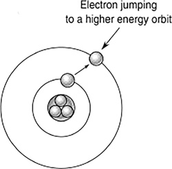
FIGURE 16.14 Electron excitation.
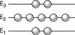
FIGURE 16.15 Population inversion.
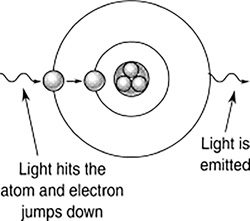
FIGURE 16.16 Stimulated emission.
16.5 THE SPEED OF ELECTROMAGNETIC WAVES
Light travels at 186,000 miles/s or 3 × 10⁸ m/s in a vacuum. A convenient conversion is that light travels 1 ft in 1 nanosecond (ns).
Example 16.1
How long does it take for a radio signal to reach a satellite orbiting 22,000 miles above the earth (Figure 16.17)?
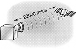
FIGURE 16.17 How long does it take for a radio signal to reach a satellite orbiting 22,000 miles above the earth?
16.5.1 Speed, Frequency, and Wavelength
The velocity, wavelength, and frequency of any wave are given by the formula:
In the case of light,
Therefore,
Example 16.2
WBEZ radio station in Chicago broadcasts at 91.5 MHz. What is the wavelength in miles and feet of this radio wave?
16.6 OPTICS
Optics is concerned with generating, gathering, bending, and focusing light for some useful purpose.
16.6.1 Opacity
Why can you see through glass and not through a concrete wall or a nontransparent material? If a material is not transparent, it is opaque. Light passes through glass and not through an opaque material because the molecules composing the glass do not absorb the light (Figure 16.18). They allow it to pass, unlike an opaque material, which absorbs the light.
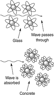
FIGURE 16.18 Light passes through glass and not through an opaque material because the molecules composing the glass do not absorb the light.
16.6.2 Reflection of Light
The angle of the incident ray equals the angle of the reflected ray.
Light must be reflected off an object to be able to see it. A light ray reflecting off a surface will reflect at the same angle at which it struck the surface (Figure 16.19). If the incident and reflected angles are measured with respect to a normal or perpendicular to the surface, then,
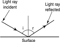
FIGURE 16.19 The angle of incidence equals to the angle of reflection.
Example 16.3
A laser beam strikes a mirror on a floor 2 ft from a wall, at an incident angle of 30° with respect to the mirror’s normal (Figure 16.20). Where will the reflected beam hit the wall?
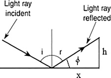
FIGURE 16.20 Where will the reflected beam hit the wall?
16.6.3 Spherical Mirrors
Cut out a section of a ball, coat the inside with something reflective, and you have a spherical mirror (Figure 16.21).
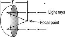
FIGURE 16.21 Cut out a section of a ball, coat the inside with something reflective, and you have a spherical mirror.
16.6.4 Focal Point
The focal point of a spherical mirror is the point where all the reflected rays pass through (Figure 16.21). A makeup mirror is an example of a spherical mirror (Figure 16.22).
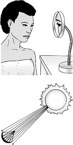
FIGURE 16.22 Spherical mirrors, such as a makeup mirror, can be used to magnify images. They can also be used to focus light into a small area. Parallel incoming rays will focus on a point a distance from the mirror equal to half the mirror’s radius.
For a spherical mirror, the focal point is a distance from the mirror equal to half the mirror’s radius.
Example 16.4
A spherical mirror of radius 20 cm will focus sunlight at what distance from the mirror?
16.6.5 Parabolic Mirror
Flashlights and automobile headlights are made with parabolic reflectors (Figure 16.23). A mirror with a parabolic shape can focus light much more sharply than a spherical mirror. Any light source at the focal point will be reflected off the mirror into a parallel of beam light. Conversely, any incoming parallel beam of light will be focused on a point. Most big telescopes are made with parabolic mirrors (Figure 16.24).
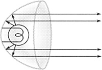
FIGURE 16.23 Flashlights and automobile headlights are made with parabolic reflectors.
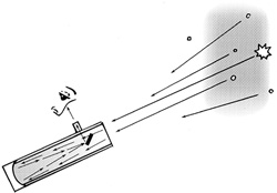
FIGURE 16.24 Many telescopes are made with parabolic mirrors.
16.6.6 Corner Reflector
Coat the inside corner of a box where the sides meet the top with something reflective and you have a corner reflector (Figure 16.25).
The astronauts left a corner reflector on the moon. It is designed so that any incoming light ray will be reflected back parallel to it (Figure 16.26).
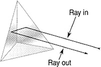
FIGURE 16.25 A corner reflector will take an incoming light ray and reflect it back, parallel to itself.
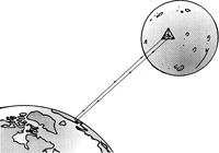
FIGURE 16.26 The distance to the moon is routinely measured by shooting a laser from earth to a corner reflector on the moon and timing how long it takes to come back.
16.7 DIFFRACTION AND REFRACTION OF LIGHT
Diffraction is the bending of waves around an obstacle (Figure 16.27). An example of diffraction is the outline formed around shadows. The light waves bend around an obstacle and, through interference, form the outline.
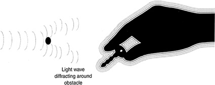
FIGURE 16.27 Light waves diffracting or bending around an obstacle.
Refraction is the bending of waves when they pass from one medium into another. An example of this is light passing from air into water. Light travels slower through water than it does through air. As a result, the wave front that enters the water will fall behind the wave in the air. The light is effectively bent because of this slowing down of the light (Figure 16.28).
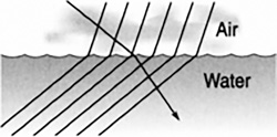
FIGURE 16.28 Light is bent or refracted when moving from air to water because the wave front slows down in the water.
The index of refraction (n) is a measure of how many times slower light travels through a material than through a vacuum (Table 16.1).
Table 16.1
Indices of Refraction Measured at a Wavelength of 589 nm
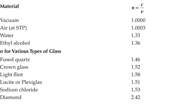
The index of refraction is the ratio of the speed of light in a vacuum to the speed of light through some material. It is a measure of how much slower light travels in a given medium than in a vacuum. The index of refraction has no units.
Example 16.5
A light wave enters a glass lens with an index of refraction 1.2 (Figure 16.29). What is the speed of light in that lens?
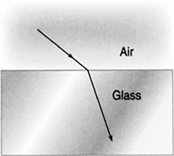
FIGURE 16.29 What is the speed of light in that lens?
16.8 LENSES
We can use the refractive properties of glass to make lenses bend and focus light. Convergent lenses are lenses that focus light (Figure 16.30). An example is a magnifying glass.
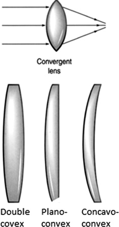
FIGURE 16.30 Convergent lens.
Divergent lenses are lenses that spread out light (Figure 16.31). An example of a divergent lens is the eyeglass prescription for someone who is nearsighted (Figure 16.32). The eye focuses an image short of the retina, where the image is supposed to form. The divergent lens corrects this by extending the focal length onto the retina.
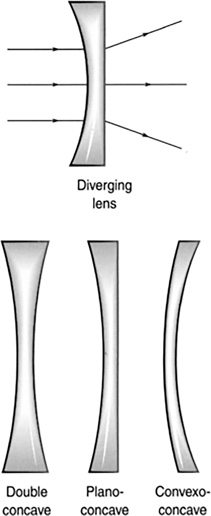
FIGURE 16.31 Divergent lens.
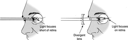
FIGURE 16.32 A corrective divergent lens for nearsightedness.
16.8.1 Thin Lens Equation
A convergent lens will focus a parallel set of light rays on a point called the focal point on an axis, called the principle axis, that is centered on and runs through the lens (Figure 16.33).
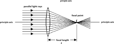
FIGURE 16.33 A convergent lens.
A parallel set of light rays can be obtained from a faraway source such as the sun. To obtain the focal length f, focus the sunlight on a point and measure the distance from lens to where the light is focused (Figure 16.33).
A lens can be used to enlarge or reduce the size of an object being viewed through the lens. The distance from the lens where the image forms di is related to the focal length f and the distance from the object to the lens do (Figure 16.34).
Other variations of this formula are:
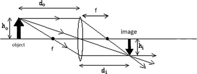
FIGURE 16.34 An object viewed though a lens will appear inverted.
To generate a light ray diagram as in the figure, follow the steps:
Draw a ray from the top of the object parallel to the axis to the lens. Where the ray strikes the lens draw a ray through the focal point.
Draw a ray from the top of the object through the center of the lens.
Draw a ray from the top of the object though the focal point on the object side to the bottom of the lens, then continue this line parallel to the axis.
An image will be formed where all the lines meet from steps 1–3.
Example 16.6
Given the focal length of a converging lens equals 20 cm, and the object is 30 cm from the lens, where does the image form?
16.8.2 Magnification
The magnification is a measure of how much larger or smaller the image is compared to the object. The magnification can be found by taking the ratio of the object distance do to the image distance di.
∎ The magnification has no unit.
∎ A negative m means the image is inverted.
The magnification relates the size of the object and image. Magnification is the ratio of the height of the image hi to that of the object ho. The height of something is always greater than or equal to zero, so the absolute value of m, |m|, is used in the following:
Example 16.7
Given the focal length of a converging lens equals 20 cm, and a 2 cm tall object is 30 cm from the lens, where does the image form, and what is the magnification and the height of the image?
Example 16.8
A 5 cm wide object 20 cm from a lens is to be imaged onto a 0.5 cm wide charge-coupled device (CCD) chip. Find a lens with the appropriate focal length and determine the distance from the lens to the CCD chip (Figure 16.35).
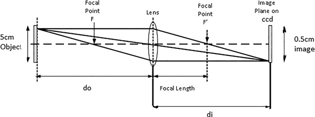
FIGURE 16.35 16.35 Find a lens with the appropriate focal length and determine the distance from the lens to the CCD chip.
The required magnification
Using the absolute value of m, , we get:
We can now find the focal length of the lens:
16.8.3 f-number
The f-number relates the focal length to the diameter of a lens.
Example 16.9
A lens has a focal length of 2 cm and a diameter of 1 cm. What is its f-number?
16.8.4 Compound Lenses
Using two or more lenses together can result in much greater magnification (Figures 16.36 and 16.37).
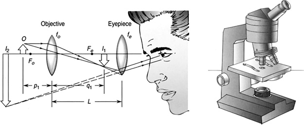
FIGURE 16.36 The microscope.
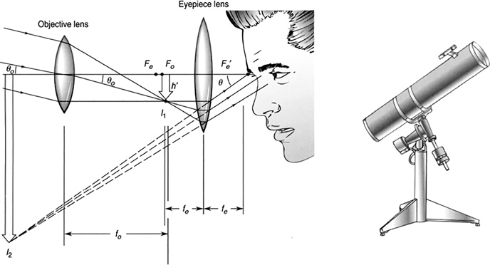
FIGURE 16.37 The telescope.
16.8.5 Aberration
Aberration is a deviation from ideal focusing of light by a lens. As a result, the image is not sharply focused. Some of the problems may lie with the geometry of the lens. Other aberrations may occur because different wavelengths of light are not refracted equally. This last problem is called dispersion.
16.8.6 Dispersion
Light refracts differently depending on its wavelength. A prism separates white light into colors because the speeds of the different colors of white light are different (Figure 16.38). As a result, they are bent at different angles, with violet bending the most and red the least.
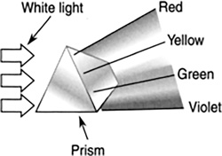
FIGURE 16.38 A prism separating the colors of white light.
16.9 INTENSITY AND ILLUMINATION
16.9.1 Luminous Intensity
The luminous intensity of a light is a measure of how much light a source emits in a given area. One unit of luminous intensity is candela, a unit that is related to candles. The brightness of light sources in the past was compared to the brightness of candlelight. Light emanating from a light emitting diode (LED) is concentrated in a light cone of about 30°. A typical LED puts out 40 millicandelas (mcd). Ultra-bright LEDs can put out 23,000 mcd. Another unit of luminous intensity is the lumen (lm).
For a light source that puts out light uniformly in all directions, the conversion from candelas to lumens is:
A common 40 W incandescent light puts out about 500 lumens. A 40 W fluorescent light puts out about 2,300 lumens, making it much more efficient than an incandescent bulb.
16.9.2 Illumination
Illumination is the measure of a light’s apparent brightness at some distance away from the source. The unit of illumination is lm/m2 or lux.
If the light radiates equally in all directions, the illumination is given by:
The light moves outward from a source that emits uniformly in all directions, creating a sphere of light (Figure 16.39). Think of the light as painting a sphere from the inside. The larger the sphere, the thinner the layer of light paint for a given amount of light. The light will appear to be dimmer to you because you are looking at only a small section of the sphere, painted thinly.
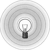
FIGURE 16.39 A light source that emits light uniformly in all directions creates a sphere of light.
Example 16.10
A light source radiates equally in all directions with an intensity of 500.0 lumens (Figure 16.40). What is the illumination 3.0 m from the source?
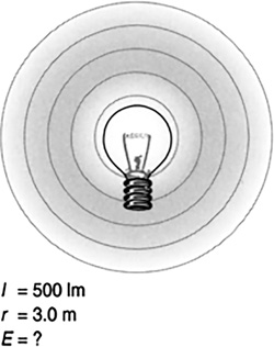
FIGURE 16.40 What is the illumination 3.0 m from the source?
16.10 OPTICAL DEVICES
16.10.1 Optical Storage
Compact discs store binary information on them in the form of bumps embedded in the plastic (Figure 16.41). The bumps are created on a thin coating of aluminum, sandwiched between two pieces of plastic. On a CD that can store 650 MB of data, the bumps are 0.5 microns wide, 0.97 microns long, and 125 nm high. They are arranged in a spiral that, if stretched out, would be 5 miles long!
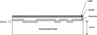
FIGURE 16.41 The bumps on a compact disc store binary ones and zeros.
The bumps reflect laser light that shines on them differently than on the flat areas. Electronics, along with a light sensor, measure the reflected light and interpret the information.
Digital video discs (DVDs) store 7.5 times more data than a CD, that is, 4.7 GB. They accomplish this by making the bumps smaller and closer together, allowing them to carry more data in the same space.
16.10.2 Photodiodes, Resistors, and Transistors
Resistors, diodes, and transistors can be made photosensitive and therefore can be activated by light (Figure 16.42).
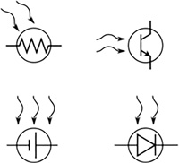
FIGURE 16.42 Photo sensors.
Photoresistors are made from a light-sensitive material such as cadmium sulfide (Figure 16.43). Their resistance lowers with light level (Figure 16.44). They are used to detect light levels in cameras, streetlights, and so forth.
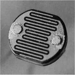
FIGURE 16.43 A photoresistive cell.
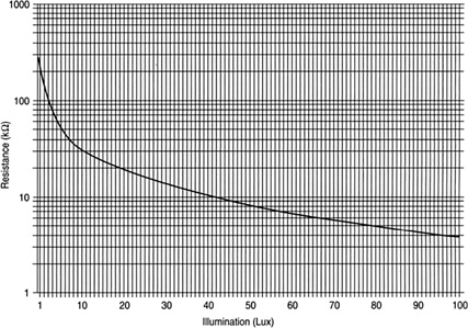
FIGURE 16.44 Typical response curve of a photo cell.
Photodiodes are essentially small solar cells in a small package (Figure 16.45). They are used to detect light by putting out a voltage proportional to the light level.
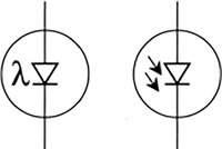
FIGURE 16.45 Schematic symbol of a photodiode.
Phototransistors have a light-sensitive base (Figure 16.46). Instead of a wire connected to the base, a window is present, allowing light through to turn on the transistor. Phototransistors have a larger output than a photodiode due to the amplifying nature of a transistor.
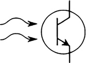
FIGURE 16.46 A phototransistor.
16.10.3 Charge-Coupled Device
Digital cameras use a device called a CCD to record an image (Figure 16.47).
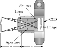
FIGURE 16.47 A digital camera using a CCD sensor.
Figure 16.48 shows how a CCD works. Light is focused on to an array of capacitors which are light sensitive. A charge builds up on each capacitor proportional to the light intensity. Each capacitor element is called a pixel. The pixels are then read by a device and sent to a processor to construct the image.
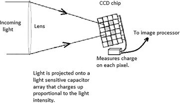
FIGURE 16.48 How a CCD works.
Example 16.11
A 1 megapixel CCD contains a square array of 1,000 × 1,000 light sensitive elements contained in a package typically smaller than 5 × 5 micron2. A 2 cm tall object is to be imaged with a lens onto 1 megapixel CCD, see Figure 16.48. What is the resolution of this image?
At least 2 pixels should be imaged, thus the resolution is:
16.10.4 Fiber Optics
A fiber optic cable is a light pipe (Figure 16.49).
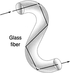
FIGURE 16.49 A light pipe.
Light can be routed around in a light pipe similar to the way water can be routed through plumbing. Light traveling through a fiber optic cable is internally reflected, bouncing its way through the cable until it exits at the end. A few fiber optic cables in communications can replace big bundles of copper wire (Figure 16.50). Signals running through copper wire dissipate heat, resulting in degradation of the signals. In fiber optics, this problem is much smaller, allowing for a much higher transmission density without degradation (Figure 16.51).
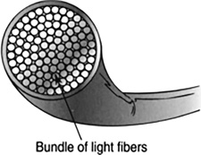
FIGURE 16.50 A fiber optic cable consists of many fibers.
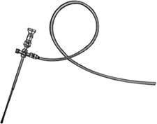
FIGURE 16.51 Fiber optics is used in medical procedures, such as laparoscopic surgery.
16.10.5 Solar Energy
Solar energy comes from the sun, warms us, makes plants grow, and drives the weather. The average illumination from sunlight is about 1,000 W/m2 at the earth’s surface.
This energy can be captured and used to heat our homes or create electricity (Figure 16.52).
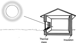
FIGURE 16.52 The average illumination from sunlight is about 1,000 at the earth’s surface.
Solar cells convert sunlight directly into electricity (Figure 16.53). They are basically a very thin diode, a PN junction, with one side transparent to light. As light makes its way to the junction, it knocks free electrons on the P side, and they are transported to the N side because of the electric field present in every PN junction. A grid is placed over the solar cell to collect these electrons on the front, and a metal film is placed on the back to act as the positive terminal. The cell now acts like a battery, deriving its energy from light instead of some chemical reaction.
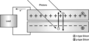
FIGURE 16.53 A solar cell.
The solar cell cannot convert all of the light energy into electricity because it is only about 20% efficient. Solar cells are sensitive to only a small band of wavelengths in sunlight. Seventy percent of the sunlight falling on the cell has wavelengths that are either too short or too long. Other losses are due to the high resistance of the semiconductors the cell is made of. To enhance efficiency, a cell is coated with a nonreflective agent to prevent the sunlight from just reflecting off the cell. A lens may be used to concentrate a large area of light onto a solar cell, increasing its light-gathering power (Figure 16.54). Currently priced at about 12 cents/kWh on average, the cost of solar power is on par with electricity from the utility companies.
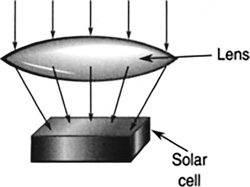
FIGURE 16.54 Lenses help collect more light to focus on the solar cell.
16.11 LIGHT SCATTERING
Our blue sky, during the day, is a result of the way sunlight scatters off of air molecules; this is called Rayleigh scattering. The air molecules scatter blue light the most and red light the least. Therefore, when you look up into the sky, you see blue everywhere. The rest of the colors contained in the white light pass right on through the atmosphere. This results in the sky appearing blue (Figure 16.55).
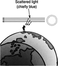
FIGURE 16.55 Blue light scatters more than the other colors in white light, giving the sky its blue color.
The reddening of the sky at night is also a result of this scattering. When the sun sets near the horizon, light must travel a greater distance through the atmosphere to reach earth than at noon. By the time the light has reached earth, all the colors have been scattered away except for red. As a result, the sky appears red (Figure 16.56).
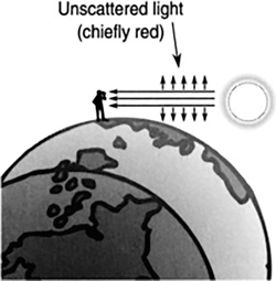
FIGURE 16.56 The sky appears red in the evening because light must travel a longer distance through the atmosphere, resulting in all colors except for red being scattered away.
16.12 CHAPTER SUMMARY
Symbols used in this chapter
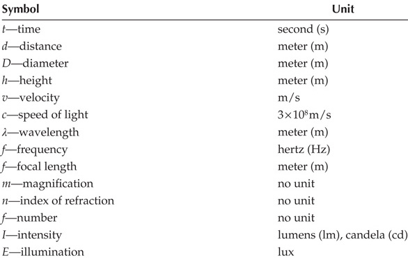
Light: Light is a wave made of electric and magnetic fields that change with time.
Light speed: Light travels at a speed of 186,000 miles/s or 3 × 10⁸ m/s in a vacuum.
Laser: Laser stands for Light Amplification by Stimulated Emission of Radiation.
Luminous intensity: The luminous intensity (I) of a light is a measure of how much light a source emits in a given area. It is measured in candelas. For a light source that emits light uniformly in all directions, the conversion from candelas to lumens is:
Illumination is a measure of a light’s apparent brightness at some distance away from the source.
The unit of illumination is lm/m2 or lux.
If the light radiates equally in all directions, the illumination is given by:
Reflection of light: The angle at which a light ray reflects off a surface is equal to the angle at which it originally struck the surface. This is called the incident angle and is equal to the reflected angle:
Spherical mirror: The focal point is a distance from the mirror equal to half the mirror’s radius.
Diffraction is the bending of waves around an obstacle. The index of refraction (n) is a measure of how many times slower light travels through a material than through a vacuum.
Convergent lenses are lenses that focus light. An example is a magnifying glass.
Divergent lenses are lenses that spread out light.
Dispersion: Dispersion is the wavelength dependence of refraction.
16.12.1 Thin Lens Equation
A convergent lens will focus a parallel set of light rays on a point called the focal point on an axis, called the principle axis, that is centered on and runs through the lens. The distance from the lens where the image forms di is related to the focal length f and the distance from the object to the lens do.
Other variations of this formula are:
16.12.2 Magnification
The magnification is a measure of how much larger or smaller the image is compared to the object. The magnification can be found by taking the ratio of the object distance do to the image distance di.
The absolute value of the magnification is ratio of the height of the image hi to that of the object ho.
f-number relates the focal length to the diameter of a lens.
PROBLEM SOLVING TIPS
When solving problems dealing with frequency, wavelength, and the speed of light, remember to convert megahertz into hertz.
PROBLEMS
List the different colors of the visible and near visible parts of the electromagnetic spectrum and their applications.
Ham radio operators sometimes bounce radio signals off the moon. If the moon is about 250,000 miles away, how long does it take the signal to reach the moon?
How long is the wavelength of an AM radio wave of frequency 550 kHz?
How does an atom emit light?
List the various steps involved in the workings of a laser.
Look at Figure 16.44. Does a photoresistor’s resistance increase or decrease with light level?
Suppose a 100 W light bulb puts out 1,250 lm of light. What is its illumination 2.0 m away?
How can you use the illumination equation to find the distance to a source of light with a known intensity?
Suppose you take a parabolic reflector with a collection area of 3 m2 and place a solar cell at its focus. How many watts of sunlight will be focused onto the solar cell if the average illumination is 1,000 W/m2? How many watts of electricity will be generated if the cell’s efficiency is 20%?
How do lenses bend light?
What is the difference between ultraviolet and infrared lights in terms of wavelength?
When white light shines on an object and the object appears to be of a certain color, what has happened to the other colors in the white light?
Why can we see through glass?
If a ¼ wave antenna is designed to work with a radio station operating at 93 MHz, how long should the antenna be?
If light strikes a flat mirror at an angle of 30 ° with respect to a perpendicular to the mirror, what is the angle of the reflected light?
How long does it take for a radio signal to reach a satellite 20,000 miles above the earth’s surface?
A radar determines the distance to an object by sending out a radio wave and timing how long it takes for the wave to propagate outward, bounce off an object, and return. If the round-trip travel time is 5.0 × 10⁻⁵ s, how far away is the object in meters?
What is the approximate wavelength of a FM radio station operating at 96 MHz?
The inside of a microwave oven is 12 in. wide. If one wavelength of a microwave spans this distance, what is the frequency of the magnetron (the source of the microwaves)?
The efficiency of an incandescent light bulb is only about 10% (only 10% of the energy it consumes is turned into visible light). The remaining 90% is dissipated as heat. How many watts of visible light does a 60 W light produce?
Light strikes a flat mirror at an angle of 30 ° with respect to the perpendicular to the surface. What is the angle of reflection?
The index of refraction of a material is a measure of how many times light slows down when traveling through it as compared to a vacuum. If the index of refraction is 1.4, what is the speed of light in that medium?
If the intensity of an isotropic light source (a source that emits uniformly in all directions) is 300 lm and is viewed 4.0 m away, what is the illumination?
What is the distance to a light source that has a luminous intensity of 450 lm and an illumination of 0.001 lux?
The electrical power out of a solar cell depends on its efficiency, the illumination of the sun upon it, and its effective area (the area of sunlight it can collect). If the area of the cell is 0.09 m2 and the illumination of the sun is 1,000 W/m2, and the efficiency of the cell is 20%, what is the output power of the cell?
Light travels 25 m through water which has an index of refraction 1.33. How long did it take to travel this distance?
If the speed of light is 186,000 miles/s, how many ft/s is this?
Electronic signals travel near the speed of light. If a signal travels at 95% the speed of light through a cable, how many feet does it travel in 1 ns?
Diamond has an index of refraction 2.42. What is the speed of light in a diamond in m/s?
A 40 W fluorescent light emitting 500 lm of light at 40% efficiency wastes 60% of its energy in generating heat. How much of the 40 W is turned into heat?
An isotropic light source (emits light equally in all directions) emits 500 lm. How many candelas is this?
Two identical light sources are 2 and 3 m away from an observer. If the observer measures 8.0 lux, what is the intensity of these light sources?
A one-quarter wave antenna has a length that is ¼ the length of the radio wave it is transmitting. If the frequency of the transmission is 10.0 MHz, how long is the antenna?
A source of light emits 100 W/m2 of light. A solar cell can collect this light and turn it into electricity. By using a lens, more light can be gathered and focused onto the cell. If a lens is capable of gathering 0.3 m2 of light and focusing it onto the cell, how many watts of light are focused onto the cell?
What is the focal point of a spherical mirror with a radius of 12 in.?
The focal length of a converging lens equals 25 cm and the object is 35 cm from the lens. Where does the image form?
The focal length of a converging lens equals 15 cm, and the image is 20 cm from the lens. What is the distance from the object to the lens?
An object is 60 cm from a lens, and the image forms 20 cm from the lens. What is the focal length?
A 2 cm tall object is 25 cm from a lens, and the image forms 35 cm from the lens. What is the magnification and how tall is the image?
A lens has a focal length of 4 cm and a diameter of 2 cm. What is its f-number?
What is the radius of curvature for a spherical mirror with a focal length of 30 cm?
A laser beam strikes a flat mirror at an angle of 20 °with respect to the normal. The mirror is on the floor reflecting the beam onto the wall 2 m above the floor. How far from the wall did the laser beam strike the mirror?