2
Development of Ultrawideband Communications Systems and Radar Systems
Terence W. Barrett
CONTENTS
2.2 Concept of UWB Communications
2.3 Historical Development of UWB Radio Communications Systems
2.4 Major Components of an UWB Radio Communications System
2.4.1 Methods for Generating Pulse Trains and Transmitter Sources
2.4.2 Methods for Modulating a Pulse Train
2.4.3 Methods for Pulse Detection and Reception
2.4.4 Appropriately Efficient UWB Antennas
2.5 UWB Signal Detection and Amplification
2.5.1 The Tektronix™ System (1975)
2.5.3 Ross and Robbins Systems
2.6 Technical Difficulties Associated with Testing for UWB Emissions Interference
2.7 General Observations on UWB Development
2.7.2 Capacity of UWB Communications Systems
2.7.4 UWB Radiation Measurements
2.8.2 Target UWB Response Aspects
2.8.5 Ground-, Wall-, and Foliage-Penetrating Radars
2.8.6 Russian UWB Radar Systems
2.9 Higher Order Signal Processing
2.9.1 Singularity Expansion Method
2.9.3 Time–Frequency Approaches to High-Resolution Target Identification
2.9.4 Time–Frequency Approaches to High-Resolution Target Detection
2.10 Summary Observations about UWB Radar
2.1 Introduction
Although there is considerable overlap in the subcomponents of ultrawideband (UWB) communications systems and UWB radar/sensor systems, it is natural to treat the history of these two systems separately for several reasons. The UWB communications system uses subcomponents based on principles that have been known for decades, whereas the UWB radar/sensor system uses subcomponents based on principles novel to the radar community. UWB radar/sensing offers the capability of high-resolution target imaging and detection, and it has achieved some commercial success in penetration and imaging of ground, wall, and foliage, whereas UWB communications systems are yet to demonstrate significant virtues. UWB radar systems are also less likely to cause interference to conventional receivers. Sections 2.2 through 2.7 discuss UWB communications, whereas Sections 2.8 through 2.11 extend the discussion to UWB radars and sensors. Both parts concentrate on the pioneering, innovative, and fundamental contributions to UWB technology. Problems involved in UWB interference testing and application are also described here.
2.2 Concept of UWB Communications
The term ultrawideband or UWB signal signifies a number of synonymous terms such as impulse, carrier-free, baseband, time domain, nonsinusoidal, or orthogonal function and large-relative-bandwidth radio/radar signals. Here, the term UWB includes all of these. The term UWB, which is somewhat of a misnomer, was not applied to these signals and systems until about 1989, apparently by the U.S. Department of Defense. Only in 2007, the IEEE STD 1672, Ultrawideband Radar Definitions established definitions that differentiated UWB radar from the conventional radar technology described in IEEE STD 686, Radar Definitions.
Contributions to the development of a field addressing UWB radio frequency (RF) signals commenced in the late 1960s with the pioneering work of Dr. Henning Harmuth at the Catholic University of America, Dr. Jerry Ross and K.F. Robbins at Sperry Rand Corp., and Paul van Etten at the U.S. Air Force’s (USAF) Rome Air Development Center and the work in Russia. The books and papers of Harmuth, published in 1969-1984, placed the basic design of UWB transmitters and receivers in the public domain. At approximately the same time, the patents of Ross and Robbins (R&R), 1972-1987, pioneered the application of UWB signals in a number of areas, including communications and radar, and also in the use of coding schemes. The Ross U.S. Patent 3,728,632, dated April 17, 1973, is a landmark in UWB communications technology. Both Harmuth and Ross and Robbins applied the 50-year-old concept of matched filtering to UWB systems.
van Etten’s (1977) empirical testing of UWB radar systems resulted in the development of system design and antenna concepts. In 1974, Dr. Rexford Morey designed a UWB radar system for penetrating the ground, which became a commercial success at Geophysical Survey Systems, Inc. (GSSI). Other subsurface UWB radar designs followed (e.g., Daniels, 1980; Moffatt and Puskar, 1976; Oswald, 1988; Pittman et al., 1982).
The commercial development of sample-and-hold receivers for oscilloscopes at Tektronix, Inc., in the late 1960s, also aided the development of the UWB field. For example, the Tektronix time domain receiver plug-in, model 7S12, utilized a technique that enabled UWB signal averaging—the sampling circuit used a transmission gate followed by a short-term integrator (Tektronix, 1968). Other advances in the development of the sampling oscilloscope were made at the Hewlett-Packard Co. These approaches were adapted to UWB designs. Beginning in 1964, both Hewlett-Packard and Tektronix produced the first time-domain instruments for diagnostics.
In the 1960s, both Lawrence Livermore National Laboratory (LLNL) and Los Alamos National Laboratory (LANL) performed original research on pulse transmitters, receivers, and antennas. Cook and Bernfeld’s (1967) book summarized developments in pulse compression, matched filtering, and correlation techniques, which began in 1952 at the Sperry Gyroscope Co. In the 1970s, LLNL expanded its laser-based diagnostics research into pulse diagnostics. Section 2.8.5 shows the numerous Russian contributions to this field during this period.
By the early 1970s, the basic designs for UWB signal systems were available, and there remained no major impediment to progress in perfecting such systems. In fact, by 1975, a UWB system—for communications or radar—was constructed using components purchased from Tektronix. After the 1970s, the only innovations in the UWB field came from improvements in particular instances of subsystems and neither in the overall system concept nor in the overall subsystems’ concepts. The basic components of UWB, such as pulse train generators, pulse train modulators, switching pulse train generators, detection receivers, and wideband antennas, were known. Moreover, particular instances of the subcomponents and methodologies, such as avalanche transistor switches, light-responsive switches, use of subcarriers in coding pulse trains, leading-edge detectors, ring demodulators, monostable multivibrator detectors, integration and averaging matched filters, template signal match detectors, correlation detectors, signal integrators, synchronous detectors, and antennas driven by a stepped amplitude input, were also known.
2.3 Historical Development of UWB Radio Communications Systems
In 1978, Bennett and Ross summarized the known pulse generation methods. Since that time, there have been numerous sessions at various conferences, including the Society for Photo-Optical Instrumentation Engineers (SPIE) meetings, the meetings held by LANL and by Polytechnic University in Brooklyn, New York, and other national meetings, where the many approaches to pulse generation techniques have been, and continue to be, discussed.
From 1977 to 1989, there were USAF research programs in UWB radar development. By 1988, the author was able to organize a UWB workshop for the U.S. Department of Defense’s Director of Defense Research and Engineering (DDRE), which welcomed over 100 participants (Barrett, 1988). During 1986-1991, there was substantial progress in UWB technology in the former Soviet Union/Russian Federation* and in China†, which paralleled the progress in the United States. There were also very active academic programs (e.g., at LLNL, LANL, University of Michigan, University of Rochester, and Polytechnic University) that focused on the interesting physics of short-pulse transmissions, which differed from the physics of continuous or long-pulse signals, especially with respect to the interactions with matter.*
*Cf. Chernousov (1965a, 1965b, 1969); Glebovich et al. (1984); Varganov et al. (1985); Meleshko (1987); Astanin and Kostylev (1989, 1992, 1997); Astanin et al. (1994); Stryukov et al. (1989); Zernov and Merkulov (1991a, 1991b); Sodin (1991, 1992); Astanin (1992); Immoreev (1991, 1997, 1998); Immoreev and Zivlin (1992); Immoreev and Teliatnikov (1997); Immoreev and Fedotov (1998); Osipov (1995); Krymscy et al. (1995); Bunkin and Kashin (1995); Efanov et al. (1997); Kardo-Sysoev (1997).
†Cf. Harmuth (1981), pp. 388-389.
Lieutenant Colonel James D. Taylor of the U.S. Air Force Electronic System Division promoted the potential of UWB radar as a defense technology for detecting and tracking cruise missiles and small radar cross-section aircraft. At that time, UWB radar had a popular perception as a counter-stealth technology. The simultaneous introduction of the B-2 stealth bomber produced a temporary moratorium on UWB research programs. For some years, UWB research took place but without reference to the term UWB. The SPIE provided one of the major forums for UWB research presentations during the 1990s. Colonel Taylor continued advancing the cause by organizing and editing Introduction to Ultra-wideband Radar Systems (Taylor, 1995a) and Ultrawideband Radar Technology (Taylor, 2000). These books provide basic information regarding UWB radar theory.
In 1994, T.E. McEwan, then at LLNL, invented the micropower impulse radar (MIR), which provided for the first time an extremely compact and inexpensive UWB radar operating at ultralow power, besides being compact and inexpensive (McEwan, 1994, 2000). This was the first UWB radar to operate on only microwatts of battery drain. The methods of reception of this design also permitted for the first time an extremely sensitive signal detection.
The methods of data encoding in UWB communications systems were introduced decades ago. For example, Sobol provides a historical perspective on microwave communications and on the data-encoding technique of pulse-position modulation, which is often used in UWB communications. He wrote that in 1943 the U.S. Army approached AT&T to develop a microwave radio system:
A similar system was under development by the British, and early models were successfully used by them in the North African campaign. The first prototypes of the U.S. Army radio, the AN/TRC/6, were completed at the end of 1943, and production started shortly thereafter. The AN/TRC-6 (Black et al., 1946) used a pulse-position modulation system that provided eight duplex voice channels through time division multiplexing and operated at 4.5 GHz (4.3-4.9 GHz).
Sobol (1984, p. 1174)
There are even patents that antedate the UWB developments of the 1970s. Having filed for the patent in 1942, De Rosa obtained the patent in 1954 for an early impulse (UWB) system (De Rosa, 1954). Also, Hoeppner (1961) patented a representation of a pulsed communications system. As in current UWB systems, Hoeppner’s system requires pulse detector timing circuitry, even if the pulses have a higher duty cycle than the later-proposed UWB systems. The essential elements of an impulse radio transmission system were known even at this time.
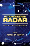
By 1975, it was possible to build a UWB system from parts purchased from Tektronix, and Bennett and Ross (1978) published the schematics for a UWB radar system, as shown in Figure 2.1. After 1970s, the emphasis swung to developing particular instances of the known technology and understanding the implications of transmitting transient pulses in a world dependent on noninterfering RF communications and sensing. Although UWB systems employ a homodyne receiver approach (cf. Barrett, 1995b)—as opposed to a heterodyne approach (superheterodyne receiver)—UWB systems remain confined by, and do not escape from, the usual engineering trade-offs of time, bandwidth, signal-to-noise ratio (SNR), and electronic complexity.
*Cf. Miller (1986); Barrett (1991, 1995a), Bertoni et al. (1993); Carin and Felsen (1995); Baum et al. (1997); Heyman and Mandelbaum (1999).
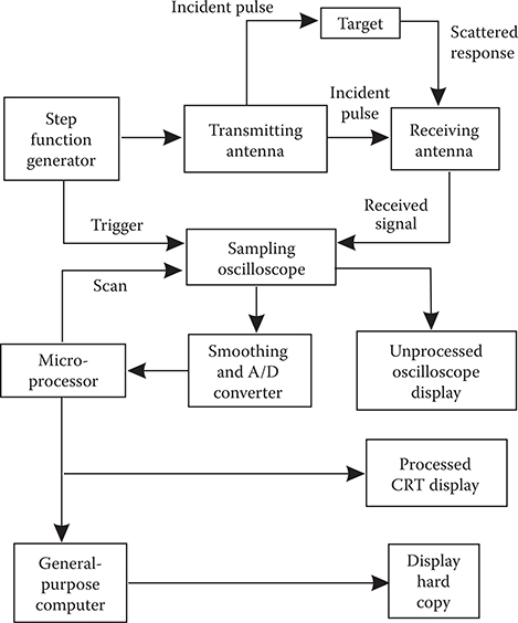
FIGURE 2.1
UWB radar system functional block diagram. (Redrawn From Figure 7C, Bennett, C.L. and Ross, G.F., “Time-domain electromagnetics and its applications,” Proc. IEEE, 1978, 66, 299-318, © 1978 IEEE.)
The UWB approach to communications is—if not a shift in paradigm—at least a shift in emphasis with respect to the use of the available time-bandwidth-power product. Figure 2.2 shows one aspect of this shift for communications applications. The fundamental emission, according to the Federal Communications Commission (FCC, 2000, p. 3), is the main lobe when viewed on a spectrum analyzer and the side lobes are not considered, or it is 2/t, where t is the pulse temporal length. It could also be the resonant frequency of the transmitting antenna that determines the center frequency of the radiated pulse (FCC, 2000, p. 2). In Figure 2.2a, the box depicts the product of (individual pulse or symbol) bandwidth. One method of defining bandwidth is B = 6.36/t, where B is the bandwidth in MHz and t is the emitted pulse duration in microseconds at 50% amplitude (voltage) points (Annex J of Chapter 5 of the National Telecommunications and Information Administration’s Manual of Regulations and Procedures for Federal Frequency Management, quoted by the FCC [2000, p. 2, footnote 8]). Duration and peak power are expressed as signal S/N:S/N = power/noisepower, where power is defined in units of J/s or V·I or kg·m2/s2·m.
It should be noted that the power spectrum or the power density spectrum, both of which are based on harmonic analysis, do not easily apply to single transient events unless careful attention is paid to the sampling rate. It should be understood that a very short-duration pulse of low energy creates fields of high electric field strength (V/m) and power (VI). With energy (J) constant, still greater field strengths and powers can be created by further shortening of the temporal length of the pulse. The FCC has correctly questioned reliance on the power spectral density (PSD) as the appropriate measure for UWB emissions (cf. FCC, 2000, p. 15, paragraph 34), yet paradoxically it has proposed (FCC, p. 18, paragraph 15) that for UWB emissions > 2 GHz, limits will still be based on PSD measurements (i.e., signal energy level per unit bandwidth). As the signal duration decreases, the bandwidth increases, and the S/N per frequency, (S/N/ω = J/s-ω or V·I·s-ω or kg·m2/s2·ms·ω), decreases. Moreover, the S/N per frequency decreases below the threshold of frequency selective receivers, which is a major argument made by the UWB proponents that UWB systems can operate in the presence of frequency selective receivers without interference. The methods used to reliably receive a UWB signal with such low S/N per frequency are shown in Figure 2.2b. These methods involve including a receiver of high sampling rate to capture in a nonsynchronous (homodyne) fashion all the signal energy in a minimum number of sampling bins and then summing across all the contemporaneous signal bandwidths. This implies a receiver with front end open to the instantaneous ultrawide bandwidth and thus also open to noise, or signal averaging or matched filtering, which lowers the data rate. This may counteract the low power per frequency by increasing to high signal-transmit power, which implies interference to other receivers, synchronous or otherwise. In other words, engineering trade-offs still apply. Each advantage offered by UWB presents a disadvantage, the cure for which is another disadvantage. Balanced optimization always remains the engineering goal.
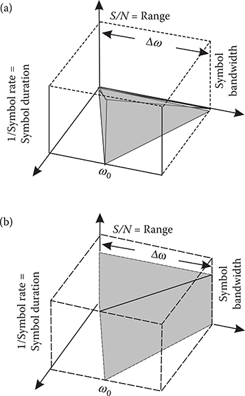
FIGURE 2.2
Time-bandwidth-S/N product representation for UWB communications systems under constant energy conditions: (a) without and (b) with high sampling rate, averaging, or high power. (From Barrett, T.W., Prog. Electromagn. Symp. 2000 [PIERS2000], Cambridge, MA, p. 366, July 2000.)
Essentially, a UWB communications system trades pulse shortness (gaining a high signal/symbol rate) in exchange for two other variables: bandwidth (which becomes wider) and S/N (which is reduced). Use of greater bandwidth requires FCC approval and a lower S/N requires signal averaging, which then lowers the signal/symbol rate and thus the channel capacity or data rate. If the systems objective is high capacity or high data rate, then lowering the signal/symbol rate, along with the fact that the symbol/signal of a UWB system has an informational value no higher than 1 bit (and after signal averaging much less), defeats the aim. Of course, these trade-offs can, to some extent, be alleviated by transmitting pulses, the lowest frequency components of which are higher than FCC Part 15 bands (above ~6 GHz), or by using higher power (if permitted and noninterfering). However, both of these strategies are also available to conventional and noninterfering wireless communications systems.
The designer cannot escape from these trade-offs. As in the case of more conventional communications systems, the designer of UWB wireless systems must balance trade-offs among high bandwidth efficiency, low transmission peak power, low complexity, flexibility in supporting multiple rates, and reliable performance as expressed in bit error rates.
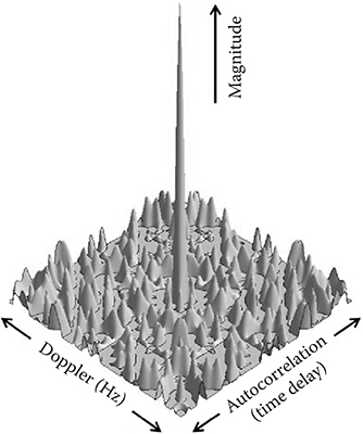
FIGURE 2.3
A form of the ambiguity function or matched filter response to a UWB pulse train, that is, imposed on an interpulse-interval code. (From Barrett, T.W., Microwave J, 44, 1, 22–56, January, 2001a.)
But even the representation of the time-bandwidth-S/N product is incomplete in assuming that the power spectrum of a UWB pulse or trains of pulses is flat. Only harmonic signals can be transmitted; mathematical distribution functions such as a Dirac delta function are not physical and are not transmittable. A form of the ambiguity function or matched filtered response to a UWB pulse train on which has been imposed an interpulse-interval temporal code—that is, the train has been dithered—is shown in Figure 2.3. There is always a central peak in the energy/power spectrum corresponding to the energy/sampling time of the individual UWB pulse, regardless of the extent of dithering. There have been claims that pulse dithering will reduce the power in a UWB pulse aperiodic train to a flat spectrum, but such a misleading prediction is due to inadequate (non-Nyquist) sampling of the individual pulse within the pulse train or because the sampling is intentionally set to the pulse repetition rate (PRR). Thus, the time-bandwidth-S/N product incompletely represents the spread of energy captured by a matched filter capable of sampling at the Nyquist rate. State-of-the-art spectrum analyzers do not sample fast enough to capture the peak power of the individual UWB pulse and thus misrepresent the energy and power in a UWB pulse train. A fast (>20 GHz) sample-and-hold oscilloscope will capture the peak power in the individual UWB pulse, but it is not suitable for capturing the peak power of singular peak power events in aggregated pulses from different emitters. Thus, apart from the electronic upset capability due to the power of the pulse repetition frequency (PRF) and the peak power of the individual UWB signal, there are also sporadic combinations of peak powers due to the individual peak powers in aggregated networks of UWB emitters. Detecting the latter is a technical challenge now met by real-time digital phosphor oscilloscopes (e.g., the Tektronix 7000 series). Only such real-time oscilloscopes are capable of capturing UWB aperiodic transient noise.
The ambiguity function representation of a dithered UWB train of signals provides an idealization of a test instrument matched not to the PRF but to the individual UWB signal. Any cut in one direction gives the power density spectrum at multiples of the set frequency. Any cut in the other direction provides the autocorrelation at multiples of a set delay time. Increasing the amount of dithering (mismatching to the test instrument as a matched filter) can result in narrowing the central peak (to a limit), but the central peak (or spike) will remain of the same height, no matter the amount of dithering.
However, it is easy to see how false claims can be made concerning the effect of dithering. If the sampling time is inadequate (too long)—as it will be with state-of-the-art spectral analyzers—then the central peak will not be captured. This inadequacy in the sampling rate of test equipment gives rise to spurious claims that dithering (applying an interpulse interval code to) a train of UWB signals results in a flat power density spectrum.
The analysis method of choice for individual UWB signals is a generalization of the Fourier transform, which captures not only signal harmonic components but also signal damping through the Laplace transform. The Laplace transform of an example UWB signal is shown in Figure 2.4. This representation of a UWB signal indicates the transient nature of the signal and does not confuse a physically transmittable pulse with a mathematical distribution function. A more comprehensive analysis of UWB communications would involve the following: measuring the peak, as well as the average, power in the time domain, with spectrum analyzers used only as ancillary equipment; describing UWB individual pulsed emissions in Laplace analysis form—an analysis form that is more general than Fourier analysis and addresses the rise and fall times (damping) of the UWB signal; and describing the UWB individual and aggregated emissions in ambiguity function form.
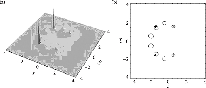
FIGURE 2.4
Two representations of the same Laplace transforms of an example UWB pulse: (a) 3D pole-zero chart. (b) 2D s versus iw plot. (From Barrett, T.W., Microwave J., 44, 2, 22-52, February, 2001b.)
The ambiguity function describes how the energy in a signal can be redistributed in the time-frequency plane by pulse train interpulse-interval temporal codes (dithering) and demonstrates two important points. First, if the pulse/pulse train energy is imagined as sand on the frequency-time plain, then no sand (energy) can be removed from the plain/plane. That is, the sand (energy) can be piled up differently and distributed differently, but none can be removed from the frequency-time plain/plane. Second, no matter how much the sand (energy) is redistributed and becomes flattened on the frequency-time plain/plane, the central peak—which is due to the peak power of the individual UWB pulse— always remains at the same height. That peak power cannot be diminished.
There have been claims by UWB proponents that a UWB signal will remain under the noise floor of a conventional receiver and thus have no influence on that receiver’s performance. The first point denies the validity of that statement, referring to the sand analogy and assuming that the sand deposited on the frequency-time plain/plane of a victim receiver is new sand (new energy). Then, the ratio of the central peak of the frequency-time description of that receiver with respect to the energy level elsewhere will be lowered. Another way of saying this is that the SNR in the receiver will be lowered, because the noise floor will be raised. If many UWB transmitters are involved in aggregated networks, the noise floor of the victim receiver will be raised more. Hence, there is no escape from normal engineering trade-offs.
The second point argues for the use of time domain testing of UWB signals, with (>20 GHz) sample-and-hold oscilloscopes for periodic signals, real-time digital sampling oscilloscopes for one-shot signals, and digital phosphor oscilloscopes for one-shot aperiodic signals monitored over time. Laboratory testing of UWB systems for interference is obviously only as accurate as the laboratory equipment used. Therefore, the laboratory testing should be supported by simulation.
It might be supposed that the comparisons between UWB communications and conventional communications could proceed using the conventional definitions for the variables in the conventional range equation. In most cases, these variables do have the same connotation, but in the case of UWB receiver noise, they do not. If the claim that a UWB signal is below the threshold of conventional heterodyne receivers is valid, it must also be valid that conventional transmitters are transmitting narrower band signals, which in many cases are above the threshold of UWB receivers. Therefore, a UWB receiver, which must be ultra broadband in its front-end, is more vulnerable to interference noise than conventional receivers of narrower bandwidth. Now, it is generally considered that the fundamental receiver noise mechanism is thermal noise and that the noise variance is related to the effective noise bandwidth of the receiver. That bandwidth is approximately one-half the signal bandwidth. It is also generally assumed that the most common communications channel is the one with additive white Gaussian noise (AWGN). In the case of AWGN, the noise arises from the receiver itself, that is, from thermal noise in the first amplifier stage. However, in the case of UWB, this may not be the only noise present in the communications channel. Even if it is the only noise present, it is conventionally assumed that an observation of this noise through an unbounded bandwidth will have unbounded power. (That assumption is unrealistic, but it is always assumed in the AWGN case.) If this assumption is adopted in the case of a UWB ultra broadband receiver, which is also a homodyne receiver, then Eb is the signal energy per bit for a direct sequence spread spectrum (DSSS) system, for example, and a UWB system, N0 is the channel noise for DSSS, and n0 is the channel noise for UWB. So, taking the above remarks into consideration (Dixon, 1984):
The UWB receiver front-end and the interference from conventional communications transmitters would preclude equivalencies. Therefore, direct comparisons of performance of UWB systems and DSSS systems by assuming equivalencies become problematic.
In comparing a UWB system with a DSSS system, it might be assumed that there is an exact comparison between the UWB bandwidth produced by the shortness of the pulse duration and the DSSS bandwidth produced by spreading from a chipping sequence. However, this comparison is misleading. In the case of UWB, all the energy across the bandwidth constitutes the signal. In the case of DSSS, however, only that energy within the spread bandwidth that is present before spreading and before transmission constitutes the signal. The remainder of the energy in the spread bandwidth gets rejected as noise after reception. The difference between the two approaches is indicated by the fact that shortening of a UWB pulse must be compensated by an increase in the peak power to preserve the energy per bit, but the energy per bit is independent of the chip rate and dependent on the data rate in the case of DSSS.
It might also be supposed that a UWB communications system has an advantage over a DSSS system in that UWB can utilize coherent addition of N pulses to achieve a bit signal-to-noise, which is N times the S/N of an equivalent DSSS system. However, the DSSS equivalent of UWB coherent addition is processing gain, not bit S/N. Furthermore, just as a DSSS system trades the bandwidth available for data transfer, and thus data rate as well, for processing gain and S/N, so does UWB trade the data rate for coherent addition and S/N. Rather than supplying an advantage, UWB coherent addition is merely a strategy for maximizing S/N in the presence of noise in the channel, just as processing gain is such a strategy for DSSS to maximize S/N. In both instances, if all else remains constant, the increase in S/N is achieved at a price—a decrease in data rate. If the data rate remains constant, then there are other penalties for the adoption of these strategies. Just as there is minimal processing gain for a high-data-rate DSSS system, so there is minimal coherent addition for a high-data-rate UWB system. Both approaches must then increase the average power, and, in the case of a UWB system, the peak and average power will eventually equalize. A possible choice for a UWB system is to increase the PRR to maintain a set data rate, but just as in the case of a DSSS system in which the chip rate is increased, the penalty for this choice is an increase in system complexity, as well as average power. Thus, there is a direct correspondence between the number of pulses per data bit in a UWB system using coherent addition and the number of chips per data bit in a DSSS system. Of course, if the data rate is of no consequence, then the choice of system and compensating penalties will be dictated by other considerations. It is also worth mentioning that these penalties are a consequence of figures of merit which address peak power. Confusion arises when comparisons are switched between peak and average powers of different communications systems, and the corresponding figures-of-merit are changed at will.
2.4 Major Components of an UWB Radio Communications System
The major components of an impulse radio system are methods for generating pulse trains (transmitter sources), methods for modulating a pulse train, methods for switching to generate RF pulse train signals, methods for pulse detection and receiving, and appropriately efficient antennas. The essential five major components were presented in the Ross U.S. Patent 3,728,632 of April 17, 1973 (Ross, 1973a) and the Harmuth books and papers (1969-1990), and since that time numerous variations on the means of implementation have been proposed.
2.4.1 Methods for Generating Pulse Trains and Transmitter Sources
In the 1970s, Harmuth (1972a, pp. 244-291, 1977b, pp. 235-399) discussed a variety of impulse radiators and presented approaches to practical radiators. Examples of radiators and selective receivers were discussed at this time.
2.4.2 Methods for Modulating a Pulse Train
A variety of methods for modulating a pulse train have been known for decades, even before the age of transistors. Harmuth (1969, 1972a, 1972b, 1972c) and (Smith, 1966, p. 438) have addressed some of the early methods.
Some of the many methods available for transmitter sources include the following:
Light-activated semiconductor switches (LASS)—these switches are generally Si-based (cf. Auston, 1975; Loubriel et al., 1993; Mourou and Knox, 1979; Nunnally and Edwards, 1991; Kingsley et al., 1995).
Light-activated bulk avalanche semiconductor switches (BASS)—these switches are generally GaAs-based (cf. Jayarman and Lee, 1972; Kingsley et al., 1995; Loubriel et al., 1993, 1995; Pocha et al., 1991; Sarkar et al. 1993; Vainshtein et al., 1988).
Thyristors based on GaAs (cf. Platts et al., 1995), semiconductor-based pulse compressor systems (cf. Edwards et al., 1995), and Marx bank pulse generators (cf. Edwards et al., 1995; Platts, 1991; Platts et al., 1995).
Avalanche drift diode generators (cf. Edwards et al., 1995; Grekhov et al., 1981, 1985).
Vacuum triodes (cf. Platts et al., 1995).
Magnetic switches (cf. Platts et al., 1995).
Low-voltage tunnel diodes (cf. Ross, 1973a, 1973b; Ross and Lamensdorf, 1972; Ross and Robbins, 1973).
High-voltage avalanche semiconductor diodes, laser diodes, and resonant microwave compressors (Didenko and Novikov, 1991; Yushkov and Badulin, 1997).
Avalanche transistor/diode methods of switching: A simple method of generating UWB signals is to use avalanche transistors, and it has been known for many years. Morey (1974) cited a transistor in the avalanche mode as a suitable means for a pulse generator in a UWB system.
Table 2.1 from Ross (1986) lists the avalanche transistor as one method (among others) for achieving pulse sources. Andrews (1986) reviewed the field of fast pulse generators and, in particular, Picosecond Pulse Labs avalanche transistor pulse generators (p. 103). Astanin and Kostylev (1989) state that “generators based on avalanche transistors are widely used” (p. 108), thereby making clear that the usage of such generators was not restricted to the former Soviet Union.
TABLE 2.1
Typical Characteristics of State-of-the-Art Pulse Sources in 1986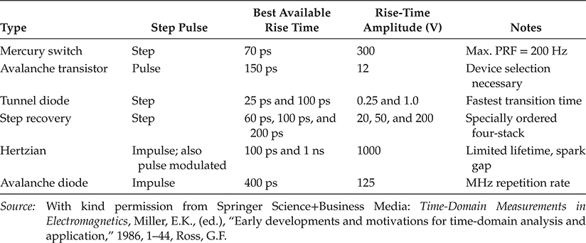
One method involves light-activated processes for switching generators—Silicon-made RF short-pulse generators using laser-induced photoconductivity in high-resistivity semiconductors were demonstrated by Auston (1975). Linear photoconductive semiconductive switching has been an active field since that time (cf. Lee, 1984; Rosen and Zutavern, 1994). A variety of semiconductors have been employed in photoconductive switches, for example, Si, GaAs, ZnSe, diamond, and SiC (cf. Kingsley et al., 1995). The activity in the field of light-activated switching has increased to such an extent that almost every year meetings on this topic are held by the SPIE. The patent by Kim et al. (1993) also addresses light-activated switching for impulse systems.
2.4.3 Methods for Pulse Detection and Reception
Methods for pulse detection and receiving include leading-edge detection, sampling bridge circuit s, monostable multivibrators, integration and averaging, templ ate signal match detection, correlation detection techniques, signal integration, and synchronous detection. All such methods have been known since the 1960s and 1970s [cf. Malmstadt and Enke (1963) for a review of early examples of these methods]. A nonexhaustive list of these well-known methods includes leading-edge detection, which has long been in use (cf. Meleshko, 1987, p.58), and sampling bridge circuit, commonplace by 1968. The Tektronix Instruction Manual for the Type S-2 Sampling Head (1968) provides a sampling bridge circuit. Also included are monostable multivibrator means, a technique that has been widely used for over 50 years (cf. Malmstadt and Enke, 1963, p. 440), integrating and averaging methods—electronic integration and averaging is also a technique that has been commonly used over the last 50 years (cf. Smith, 1966, p. 450)—and the commonplace template signal match detection (e.g., Meleshko, 1987, Figure 32, p. 65). A template match is essentially a logical operation or a cross-correlation satisfying the long-known Wiener-Hopf equation. It should be noted that template pulse mixing of a signal with a gating pulse is not the same as summing a signal with a strobe pulse, and it is also a much less sensitive detection operation.
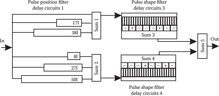
FIGURE 2.5
The Harmuth sliding correlator. (Reprinted from Antennas and Waveguides for Nonsinusoidal Waves, Harmuth, H.F., © 1984, with permission from Elsevier.)
Correlation detection of RF signals is now universal (cf. Lee, 1960; Skolnik, 1962, p. 275). The sliding correlator as applied to impulse communications and radar was reported in the open literature long ago (cf. Skolnik, 1962, p. 143 and Chapter 6 “Advanced Signal Design and Processing”). Other examples of early sliding correlators were presented by Harmuth (1981, 1984), which are shown in Figure 2.5.
Signal integration methods to match a preset criterion (e.g., summed amplitude) are commonplace. For example, the 1968 Tektronix sampli ng circuit is a transmission gate followed by a short-term integrator (Tektronix, 1968). Synchronous detection methods are widely used and are long-known procedures. Figure 14-86c in the work by Fink and Christiansen (1975, pp. 14-69) shows a product (synchronous) detector. This type of detector has been used since the advent of single-sideband transmission.
In addressing monocycle signals from antennas driven by stepped amplitude (ramp function) driver methods, Cronson (1975) showed that virtually any frequency-coded pulse could be generated by a step function (cf. Ross, 1986, p. 11). This method has also been studied for a long period of time (see Harmuth, 1981, p. 4854, 77; 1990, Preface and “Section 1.7—A Guide to Reading,” p. 52).
Use of subcarriers in pulse trains, that is, subcarrier modulation, is a well-known modulation method and is explained in many textbooks. Transferring the method to the time domain introduces no new principles. The use of subcarriers and subband coding is a well-established field in electrical engineering. Later attempts to patent the well-known modulations such as frequency modulation (FM), amplitude modulation (AM), phase modulation, frequency shift keying (FSK), phase shift keying (PSK), pulse FM, and Manchester coding, if taken seriously, would undermine the field of radio communications inasmuch as these methods are the backbone of this mature field.
2.4.4 Appropriately Efficient UWB Antennas
The antennas used in UWB communications, or being considered for use, include loaded dipoles, transverse electromagnetic (TEM) horns, biconicals, ridged horns, and spiral and large-current antennae. All have a variety of merits and demerits (Allen et al., 2007; Evans and Kong, 1983a, 1983b; Ross, 1968; Shantz, 2005; Smith, 1984; Susman and Lamensdorf, 1971; Theodorou et al., 1981; Wicks and van Etten, 1991; Wohlers, 1970).
2.5 UWB Signal Detection and Amplification
There are a number of approaches to the detection and amplification of trains of UWB signals. In most cases, there is an allocation of one-to-many in the assignment of bits to pulses to be transmitted. After 1945, the use of the correlation detection receiver became commonplace. Skolnik (1962), in his introductory book, described the use of correlation methods in the detection of weak signals and also a correlation detector, which is shown in Figure 2.6. He cited the following earlier references: Lee (1950), Lee and Wiesner (1950), Singleton (1950), Fano (1951), Rudnick (1953), George (1954), Green (1957), Horton (1959), and Raemer and Reich (1959). Fink and Christiansen (1975) described the synchronous detector, which is shown in Figure 2.7. There are a variety of ways to trigger the receiver—on the pulse rise time, level-detection, or integration over time.
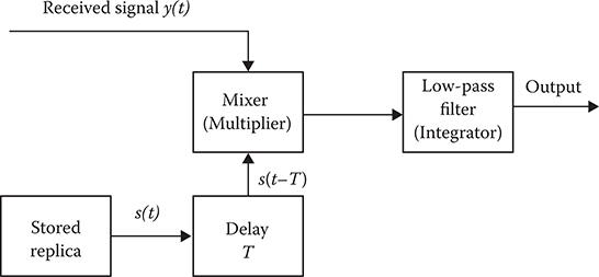
FIGURE 2.6
Block diagram of a cross-correlation receiver. (From Skolnik, M., Introduction to Radar Systems, Figure 10.3, McGraw-Hill, New York, © 1962. With permission from McGraw-Hill.)
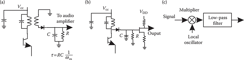
FIGURE 2.7
AM detector circuit examples: (a) AM envelope detector, (b) peak detector, and (c) product detector. (From Fink, D.G. and Christiansen, D., Electronics Engineers Handbook, Figure 18.75, McGraw-Hill, New York, © 1997. With permission from McGraw-Hill.)
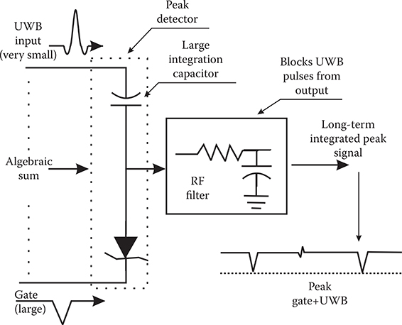
FIGURE 2.8
The MIR and peak detector. (Adapted from McEwan, T.E., Ultra-Wideband Radar Motion Sensor, U.S. Patent 5,361,070, November 1, 1994.)
In the case of the correlation receiver detector, UWB and gate pulses are multiplied to produce a short-output unamplified pulse whenever there is a coincidence. Next, the resultant is fed to a (short-term) integrator or averager to produce a reduced amplitude stretched signal output. If the integrator time is sufficiently long (for a conventional correlator), or a second long-term integrator is employed, the output will then represent the average of the many high-repetition rate pulses fed to the correlator. Unfortunately, the integrator not only acts as a detector but also reduces the input amplitude in the step from narrow-pulse, low-duty cycle to averaged output. The long-term integrating correlator thus effects a many-to-one detection of averaged inputs before any amplification.
The MIR, or “radar on a chip,” offered an alternative to correlation detection (McEwan, 1994, 2000). The MIR, shown in Figure 2.8, uses an integrating peak detector (McEwan, 1994), as opposed to the multiply-and-average correlation receiver detector previously described. In the case of the MIR receiver detector, UWB and gate pulses are summed algebraically to form the input to a peak detector. In this case, the low amplitude UWB pulse and the high-amplitude gate pulse, which when summed, are above the threshold for peak detection, but individually the pulses are not above the threshold. Moreover, it is not a single UWB pulse that, together with the gate pulse, provides the peak detected signal but the (long-term) summing of a series of UWB inputs. Thus, the detector is triggered by the simultaneous occurrence of a summed series of low-amplitude UWB signals and a coincident large amplitude gate pulse that, together, are algebraically summed. The coincident summing method of a large gate input and summed low-amplitude signals provide a many-to-one, peak signal detection process.
2.5.1 The Tektronix™ System (1975)
In 1968, Tektronix offered for sale a sampling head consisting of a strobe generator, a sampling bridge as shown in Figure 2.9, a blow-by and trigger pickoff, and a preamplifier. By 1975, it was possible to build either a UWB communications system or UWB radar using Tektronix laboratory test equipment. Figure 2.10 shows such a system built using a Tektronix 7S12, an S-4 sampler for receiving means, and an AM502 differential amplifier with filters as signal-processing means.
It is instructive to examine the means of achieving detection. The sampling bridge circuit does not amplify, but merely provides, an error signal. Referring to Figure 2.9, the Tektronix manual states as follows:
During the sampling time, the strobe pulses forward bias D5 and D6. By normal bridge function, the conduction of D5 and D6 charges or discharges C5, C6, C7 and C8. The voltage charge on these capacitors changes about 2 1/2 percent of the difference between the feedback and DC offset voltage and the incoming signal voltage. This voltage change, called the error signal, is amplified in the preamplifier.
Thus, diodes D5 and D6 form a sampling bridge or transmission gate driven by strobe pulses at J51 and J53. Resistors R5 and R6 = 200Ω and capacitors C5 and V6 = 5 pF form a short-term integrator (balanced configuration) with a 1-ns time constant. D5 and D6 conduct for approximately 40-50 ps, so that integrators charge to about 2½% of the signal input voltage during the time that the D5 and D6 conduct, providing a voltage-transfer efficiency of 2½%. Therefore, his approach, although much used and imitated, is nonetheless an inefficient detector.
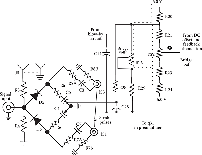
FIGURE 2.9
Textronix™ sampling bridge circuit. (Used with permission from Tektronix, Inc., Instruction Manual: Type S-2 Sampling Head, S.W. Millikan Way, P.O. Box 500, Beaverton, Oregon 97005, © 1968.)
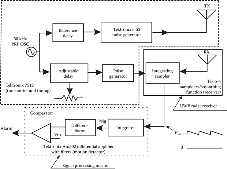
FIGURE 2.10
UWB system constructed of purchased Tektronix, Inc. components. (From Barrett, T.W., Microwave J., 44, 1, 22-56, January, 2001a. Used with permission from T.E. McEwan.)
2.5.2 Harmuth Systems
Beginning with publication of the first edition of Transmission of Information by Orthogonal Functions in 1969, Dr. Henning Harmuth addressed UWB in all its manifestations, but under the synonyms impulse, carrier-free, time domain, nonsinusoidal, orthogonal function, Walsh functions, and large-relative-bandwidth radio/radar signals. Remember that the term UWB dates from 1989. The five basic subcomponents were also addressed in early representational form and with the electronics available at that time. The second edition of the same book (Harmuth, 1972a) contains a chapter called “Nonsinusoidal Electromagnetic Waves” (Ch. 6, pp. 244-291), which discussed a variety of impulse radiators and the selective reception of impulse signals in mobile communications (cf. Section 5.4: Signal Selection and Synchronization, pp. 282-291, with a correlation receiver shown in Figure 189 on page 289 [Figure 5.0.1]).
Harmuth (1972a, 1972b, 1972c) described transmitters and selective receivers for periodic waves with arbitrary time variation within the period. Harmuth (1977a) reported a more advanced form of the receiver and discussed “pulse compression”—actually signal averaging. The work of Harmuth (1977b) contains Chapter 3, “Electromagnetic Waves With General Time Variation,” with the sections Practical Radiators, Practical Receivers, and Applications to Radar. Photographs of a radiator and a selective receiver are shown, and oscilloscope recordings of nonsinusoidal waves—specifically their electric field strengths—are also displayed. A correlation receiver for selective reception is shown in Figure 9 of Harmuth (1975).
Harmuth’s Nonsinusoidal Waves for Radar and Radio Communication (1981) contains Chapter 4, “Selective Receivers,” and Section 4.6, Receiver for Nonperiodic Waves. The circuit shown in that book is a correlation circuit. The correlation receiver or pulse compressor was recognized at this time to be the generalized equivalent for waves with arbitrary time variation of the tuned resonant circuit for the selective reception of sinusoidal waves. The pulse compression circuits in this reference have also been published in Harmuth (1979, 1980).
The work of Harmuth (1984) contains Section 1.2, Transmitter and Receiver for Nonsinusoidal Waves; Section 1.3, Nonsinusoidal Spread Spectrum Radio Transmission; and Section 1.4, Pulse Agility Versus Frequency Agility. All of these address the major components of a UWB system.
Thus, by the early 1970s, the generic system and all of the generic subcomponents for UWB systems, of whatever form, were in the public domain, and by the early 1980s, they had been extensively discussed.
2.5.3 Ross and Robbins Systems
Robbins (1972), Robbins and Robbins (1974), Ross and Robbins (1973, 1987), Ross (1973a, 1973b), and Ross and Mara (1994) are all patents addressing specific embodiments of a UWB radio receiver.
The patent by Ross (1973) disclosed an impulse radio encoding intelligence on a train of pulses by pulse interval modulation or pulse position modulation (Ross, 1973, paragraph 9). This patent recognized the utility in communications systems of a wide instantaneous bandwidth (as opposed to the sequential bandwidth). Subsystems of a UWB radio were disclosed by Robbins (1972), Ross and Lamensdorf (1972), and Robbins and Robbins (1974, 1987). Figure 2.11 shows the patented circuit diagram.
These early patents recognized that the pulse train could be modulated by a code scheme and that this method was known even prior to the patents themselves. For example, Ross (1973, paragraph 13) states that
it will be understood by those skilled in the art that a variety of ways is available in the prior art for impressing intelligence on the carrier-less baseband pulses of transmitter 2, and for abstracting that intelligence at receiver 3 by well established demodulation techniques operating on the relatively long pulses generated in receiver 3.
In 1978, Bennett and Ross published Time-Domain Electromagnetics and Its Applications. These authors wrote at a time when the term “baseband” was preferred to “UWB” or “time domain,” but all these terms are synonymous. The essential five major components of a UWB system had been already presented by Ross (1973) using methods of implementation long in use as the following quotation shows:
The baseband pulse receiver 3, as has been seen, may be employed in the novel communication system to receive intelligence communications in a variety of ways, such as . . . Equivalent electronic operation may be readily visualized . . . More sophisticated arrangements for conveying intelligence messages from transmitter 2 to receiver 3 are readily apparent to those skilled in the art.
Ross (1973, paragraph 13, line 20)
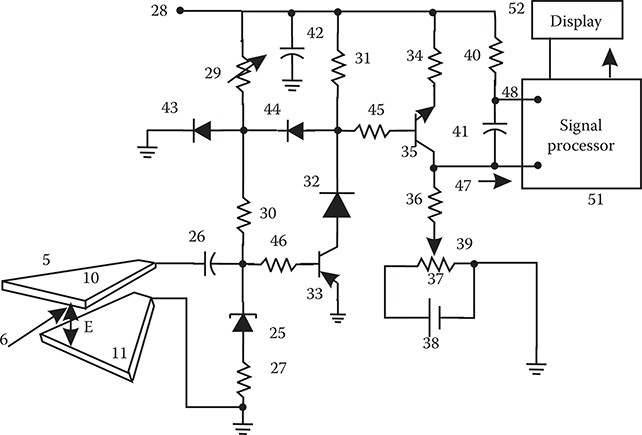
FIGURE 2.11
Circuit diagram showing components of a UWB receiver. (Adapted from Ross, G.F. and Robbins, K.W., BaseBand Radiation and Reception System, U.S. Patent 3,739,392, June 12, 1973.)
In addition:
Similarly, pulse interval modulation in transmitter 2 and cooperative demodulation in receiver 3 may be employed for conveying intelligence messages. It will be understood by those skilled in the art that a variety of ways is available in the prior art for impressing intelligence on the carrier-less base band pulses . . . and for abstracting that intelligence . . . by well established demodulation techniques . . .
Ross (1973, paragraph 13, line 55)
The claims of the Ross (1973) patent refer to particular instances of the five basic components.
2.6 Technical Difficulties Associated with Testing for UWB Emissions Interference
The testing of the effects of UWB emissions on conventional receivers is extremely complicated and difficult. This is because there are many different kinds of UWB single pulses, which can range from 0.5 to 10 ns, for example, and possess different rise times or onset times, damping or fall times, and harmonic modulated components or ringing, all according to the individual drivers and antennas. There is no generic UWB individual signal or pulse. All are damped transients.
There are many different kinds of PRFs possible for the many different individual UWB signals. There is no generic UWB PRF. There are many different interpulse-interval temporal codes possible, which can be imposed on the many different PRFs possible for the many different individual UWB signals. There is no generic code.
Measuring the peak power of the individual UWB pulses cannot be accomplished in real time, but the individual pulse case can be measured with a high-frequency (e.g., 20 GHz) sample-and-hold oscilloscope. (A state-of-the-art spectrum analyzer can only provide a distorted average of the true power.) It is not true, as has been claimed, that a UWB transmitter emits at the power level of a hair dryer. This is a dubious statement if average power is intended; it is a false statement if peak power is intended or if the aggregated average power of disparate UWB emitters is intended.
In a network, many UWB transmitters will operate simultaneously and autonomously, constituting aggregate aperiodic interference. A sample-and-hold oscilloscope can provide a measurement of a single pulse applied repetitively, but as an aggregate of UWB emitters is continuously changing (aperiodic), this approach is not applicable—even if a large enough aggregate of asynchronously operating transmitters could be assembled. A sample-and-hold oscilloscope samples high-frequency signals utilizing a low analog-to-digital (A-D) sampling rate and using “random interleaved sampling” of a periodically repeated signal. That is, by periodically repeating a signal, such oscilloscopes permit high effective sampling rates with a lower actual sampling rate. The emissions of an aggregate of disparate pulses at disparate PRFs with disparate superimposed temporal codes constitute a noise of aperiodic transients. These aggregate emissions are discontinuous, aperiodic, and nonrepeating, so a sample-and-hold oscilloscope is not the appropriate test equipment. A real-time oscilloscope is the appropriate test equipment, including the Tektronix TDS 7000 series Digital Phosphor Oscilloscopes (DPO), for example, which sample at over 20 GSps and which store and analyze complex signals in real time, using three dimensions of signal information—amplitude, time, and distribution of amplitude over time. The Tektronix TDS 694C Digital Storage Oscilloscope (DSO) can provide accurate delta time measurements of ±15 ps and a sampling rate of 10 GSps.
Such a noise of aperiodic transients may or may not be approximated by white noise, but a more likely approximation is either band-limited noise or colored noise. However, if an aggregate of UWB emissions were to be approximated by white noise, then each possible victim receiver would need to be tested individually for electronic upset potential. The individual testing of victim receivers is necessitated by the well-known nonlinear properties of receiver front-ends, and each receiver-type could be nonlinear in its own way.
Even here, there are technical difficulties associated with a noise-of-aperiodic-transients (perhaps approximated by white noise) analysis of victim receivers, due to the requirements that the noise be first recorded in real time while it is applied to the victim receiver, and then that recording must be correlated with the receiver’s immediately following response. The aforementioned Tektronix DPOs can provide real-time recording over substantial time if sufficient memory is made available.
Confronted with the technical difficulties associated with the experimental testing for periodic and aperiodic aggregate UWB emitter interference, there would appear to be a strong argument for simulation, rather than experimental testing, of such aggregate interference over the time-frequency plane.
Note also that the FCC requires power limitations and restrictions on power at designated band edges. Moreover, the present FCC Part 15 rules do not permit damped wave emissions or the ringing of antennas, that is, spark gap transmissions. In other words, the FCC Part 15 rules require a signal carrier or average frequency for very good reasons: Before 1927, when the precursor to the FCC was formed, such emissions were a major source of interference.
After hearings in 2001 and 2002, the FCC issued 47 U.S.C. Sections 154, 302a, 303, 304, 307, 336, and 544A (Subpart F—Ultra-Wideband Operation to Part 15, Radio Frequency Devices). This regulation established UWB as a commercially viable technology for unlicensed short-range radars for ground penetration, through-wall and medical imaging, surveillance systems, and handheld devices. Each section of the regulations defines uses, establishes restrictions, and specifies maximum measurable power levels in dBm for 1-MHz and 1-kHz bandwidths. Chapter 4 presents a complete extract of the regulations pertaining to UWB signals.
2.7 General Observations on UWB Development
In summary, the pioneering work of Harmuth, Ross, Robbins, van Etten, and Morey, as well as the extensive work in the former Soviet Union/Russian Federation, defined UWB systems, both radar and communications, and did so in a very practical manner using the electronics of the time. Others have contributed to particular instances of the subsystems described by these pioneers, but after the pioneering contributions, no one can, or should, claim to have invented the field of UWB radio, radar, or communications or to have invented a particular component or components, which made it practical. There never was a time that invention of a particular subcomponent was required for UWB systems to become possible, except, perhaps, the sample-and-hold oscilloscope in past times and the real-time digital phosphor oscilloscope in recent times. In the commercial arena, UWB radar/sensor systems have been utilized since the 1970s.
A number of summary observations can be made concerning the historical development of UWB. There is nothing new about the fundamental design of subsystems of a UWB communications system or any component part. Subsystem concepts of certain levels of sophistication or efficiency were readily available to G. Ross when he obtained his 1973 patent for a UWB communications system.
2.7.1 Interference Issues
In the case of UWB communications systems, what is new is the assumption that such systems can coexist without interference with other communications systems, which use synchronous receivers, and are regulated by conventional FCC spectrum habitation requirements. This assumption specifically requires that the receivers of conventional systems not only normally operate at higher average power/frequency thresholds than do those of UWB receivers (which must achieve acceptable signal-to-noise levels over time either by signal averaging or by high instantaneous signal power levels) but also are not normally subject to electronic upset by high-peak power, that is, transient UWB signals. These are two separate requirements that are usually assumed identical . Note that the FCC Section 45 regulations state that
. . . UWB devices may not be employed for the operation of toys. Operation onboard an aircraft, a ship or a satellite is prohibited.
This assumed absence of interference of UWB communications systems with other conventional receivers, and also of the electronic upset of a variety of forms of electronic equipment (e.g., Global Positioning System [GPS], which operates in the 1164.1215, 1215.1240, and 15591.610-MHz frequency bands), has yet to be adequately validated (cf. Aiello et al., 2000; FCC, 2000). There is a second assumption that pulse signals above 2 GHz are relatively noninterfering due to propagation losses (FCC, 2000, p. 13, paragraph 27). Indeed, the effect of transient RF signals, as opposed to steady-state signals on materials and circuits, is a complex subject, but poorly understood (cf. Barrett, 1991, 1995a). Moreover, the effect of a train of aperiodic transient signals on conventional receivers and forms of electronic equipment may be a nonlinear temporal summation of the individual transients and a function of the relaxation time of a particular material or a particular circuit. Making the problem of interference even more complex is the fact that, although there is a short list of electronic materials, there is a long list of possible electronic circuits in victim receivers, each with a specific relaxation time regarding possible variables affecting susceptibility to interference. According to the FCC,
typical front-end bandwidths before the first mixer in receivers; typical dynamic range limits of receiver mixers; typical IF bandwidths; and required signal-to-interference ratios for reliable performance of the system assuming interference is white Gaussian noise . . .
FCC (2000, p. 14, paragraph 33)
These variables are, indeed, important. However, what is meant by “typical” is usually typical performance with respect to continuous, rather than transient, signals. Furthermore, a pulse transient is a broad spectral bandwidth signal (mathematically), but the frequencies are precisely phase-locked, not randomly phase-related as in white noise. Therefore, it is not clear that these “typical” measurements will provide an accurate prediction of interference by real transient signals. Despite this lack of knowledge concerning interference susceptibility, some UWB proponents do not believe in cumulative interference (cf. FCC, 2000, p. 21, paragraph 46).
In the case of more than one UWB communications system operating in asynchronous mode, the assumed absence of UWB-induced interference to other locally operating UWB systems is also yet to be validated. This form of interference, which may be absent or rare in the case of UWB radar, may yet be anticipated to be commonplace in the case of more widely used UWB communication systems.
2.7.2 Capacity of UWB Communications Systems
Shannon’s channel capacity laws are universally valid and apply to UWB communications systems, regardless of whether a government limits the bandwidth and the power used. However, UWB communications systems are yet to be evaluated with respect to both bandwidth efficiency and power efficiency. UWB communications systems’ bandwidth efficiency rating—the measure of bandwidth (i.e., real bandwidth, not merely the bandwidth that can be detected above conventional receiver thresholds) used together with data rate achieved in efficiency ratings—is presently extremely poor. UWB systems’ power efficiency rating—distance achieved for power (peak not average) used—is also poor. [A declared motivation of the FCC interest in considering permitting the operation of UWB systems is that it “would permit scarce spectrum resources to be used more efficiently” (FCC, 2000, p. 1)]. However, the aim to achieve efficiency addresses the issue of whether UWB transmissions do or do not interfere with the reception of conventional frequency receivers, that is, whether the noise floor of such receivers can be utilized without penalty. This is a different efficiency aim than the aim to achieve the highest data throughput through a channel of precisely defined and restricted bandwidth. Perhaps, it is not even an aim in efficiency. Engineering trades of time, bandwidth, and power assume a zero-sum game. Some proponents of UWB technology tacitly acknowledge the zero-sum game but claim that the S/N penalties from “reuse” of spectral areas already occupied by conventional narrow and broadband systems are spread over many victim receivers. Therefore, the argument goes, the penalty per victim receiver is small. Thus, rather than using the “scarce spectrum resources more efficiently,” operation of UWB communication systems would be an exercise in interference tolerance because there must be interference regardless of how little it is. But tolerance is not efficiency, and the amount to be tolerated is not trivial.
A UWB communications system is a strategy—a limiting case strategy—of utilizing a communications channel’s time-bandwidth-power product, bypassing the FCC bandwidth restrictions and allocating extremely broad instantaneous bandwidth to the symbol/signal. There are, of course, other strategies and other approaches to utilizing that same product but keeping within FCC guidelines. In the case of UWB radar/sensing, there are proven and demonstrated advantages for using UWB systems in precisely defined situations. However, the claimed advantages of the UWB communications approach are that—if noninterfering with other communications systems, which is more than doubtful—the approach provides modest data rates but robust communications in the presence of environmental interference factors and that the approach is superior in the presence of multipath transmissions. These claims may prove valid but are yet to be proven under normal operating conditions.
2.7.3 UWB Transmitters
A UWB communications transmitter system to a great extent shares the same systems configuration—if at lower power—as that of an electronic upset weapon or jammer. The differences lie mainly in the signal power levels at a set distance. As noted before, the transient response of a victim receiver or equipment is material- and circuit-dependent. The transition set of characteristics at which a noninterfering UWB communications transmitter becomes an electronic-upset UWB jammer is yet to be defined. Furthermore, once defined, it may be assumed that the transition set of characteristics will always be relative to the devices affected by the upset/interference. Transient effects are more complex than the steady-state effects. Therefore, regulatory rule-making will have to be complex.
In the recent past, and in the case of continuous wave systems, standards of emission have relied on PSD measurements. However, it is well known that the PSD measure, with its origins in harmonic analysis and with a relationship to the autocorrelation function, is an entirely inappropriate measure of transient and UWB signals. The PSD is an even function of frequency and possesses no phase information about the signal. A transient signal is not an even function of frequency, and a valid peak power measurement is critically dependent on signal phase. Some proponents of UWB systems have pointed to a low PSD as an indication of negligible interference potential with respect to narrowband receivers when, in fact, such a harmonic analysis is an inappropriate continuous wave (harmonic) analysis for a signal transient and the test instrument used to support such claims samples too slowly. A fast-rise-time pulse can produce multiple harmonic responses in a narrowband receiver, as well as considerable destructive heating effects.
The FCC publication of 47 U.S.C. Sections 154, 302a, 303, 304, 307, 336, and 544A (1), Subpart F—Ultra-Wideband Operation to Part 15, Radio Frequency Devices specifies the acceptable measurements of radiation from UWB devices (see Chapter 4).
2.7.4 UWB Radiation Measurements
The measurement of peak power levels is only as accurate as the sampling rate of the measuring device. It is worthwhile observing that a sampling rate is a measure of operations over time. Therefore, in assessing the peak power of a UWB transmitter, it is preferable to take the frequency bandwidth as being of secondary importance and focus on the signal duration and its rise time. If the reciprocal of the signal duration and rise time are greater than half the sampling rate of the measuring instrument (i.e., greater than the Nyquist rate), the measured power is not a true peak power measure. Yet some UWB proponents believe that the peak output is not the crucial variable in causing interference to a narrowband receiver but that only the PSD of the pulse and the PRF are causes of that interference (FCC, 2000, p. 19, paragraph 41). The FCC has proposed two methods of measuring peak power: the peak level of the emission over a bandwidth of 50 MHz and the absolute peak output of the emission over its entire bandwidth (FCC, 2000, pp. 19-20, paragraph 42). Of course, both proposals beg the question of how peak power is to be measured. The peak power in a 1-GHz monocycle signal measured by an instrument with a sampling rate of less than 2 GHz is actually an average power regardless of the emission bandwidth— instantaneous or sequential—sampled. Casting around for an appropriate measuring instrument, some faith has been placed in a pulse desensitization factor correction of an inadequately sampling spectrum analyzer (FCC, 2000, p. 23, paragraph 51, footnote 107), a method which guesses a true measure on the basis of measurement at an inadequate sampling rate (FCC, 2000, p. 24, paragraph 51). This method is clearly inadequate. All things considered, the (appropriately Nyquist-) sampling osci lloscope is probably an adequate measuring instrument (FCC, 2000, p. 53, paragraph 24) but only for the individual UWB pulse. The measurement of an asynchronous, aperiodic aggregate of UWB emitters can only be undertaken by real-time oscilloscopes such as the Tektronix 7000 series of DPOs, even if the aggregate could be assembled.
There have been claims by UWB proponents that a UWB signal will remain under the noise floor of a conventional receiver and thus provide no influence on that receiver’s performance. This claim is invalid. In the case of a single UWB emitter, the SNR in a victim receiver will be lowered because the noise floor will be raised. If many UWB transmitters are involved in aggregated networks, the noise floor of the victim receiver will be raised further. Thus, there is no escape from normal engineering trade-offs.
Time domain, not frequency domain, interference testing of UWB signals should be pursued, with (>20 GHz) sample-and-hold oscilloscopes and real-time DSOs for measuring individual pulse rise times and with DPOs for measuring aperiodic trains of aggregated emitters. Laboratory testing of UWB systems for interference is obviously only as accurate and as suitable as the laboratory equipment used. Laboratory testing with inaccurate and unsuitable test equipment provides invalid test results and supports invalid claims on performance. Simulation and analysis should support this laboratory testing.
Compounding this stew of unknowns is the UWB field in general and the development of UWB communications systems, which have been plagued by exaggerated performance claims in the public press, invalid priority and originality claims, and massive and ferocious legal and political activity. These circumstances amount to truly a unique phenomenon even by the standards of the times.
2.8 UWB Radars and Sensors
2.8.1 Overview
UWB radars/sensors also probe the target’s optical response more effectively, promise the capability of high-resolution target imaging and detection, and, in some application areas, have achieved commercial success in ground, wall, and foliage penetration; synthetic aperture radar (SAR); and target imaging. This section presents the pioneering, innovative, and fundamental contributions to the field.
2.8.2 Target UWB Response Aspects
A UWB radar or sensor system is perhaps more unconventional than a UWB communications system, not primarily in system components but in the physics involved, in most cases, the signal-target interactions. In the UWB radar case, the transmitted signal length cτ is shorter than the target. Conventionally, the complete radar cross section of any target can be specified by four complex numbers for a given frequency and set of orientation angles in a scattering matrix. In the case of UWB signals, this description of the radar cross section is still valid. However, the number of frequency components in the UWB transmitted signal is large, and different scattering components on the target will not only have different resonant frequencies but also, due to their spatial separation on the target, reflect the illuminating short-duration UWB signal at different times. Therefore, the UWB signal return is the sum of separate returns spread out discontinuously in time and consists of multiple time-separated scattering matrices, reflecting the separate spatial interactions on the target.
With respect to a conventional radar signal, which, in most cases is longer in spatial extent than the target, the target’s scattering matrix is not discontinuous in time. Therefore, with respect to most conventional radar signals, the target is a point scatterer—in contrast, in the case of UWB radar signals, the target response is decomposed into a collection of individual scattering components.
Using pulse compression techniques and chirped signals, conventional radars can also resolve a target into its individual scattering components, but only if the echo frequency difference Δf between, for example, two individual scattering components is equal to the reciprocal of the uncompressed pulse width τ or Δf = 1/τ.
Therefore, if the target subcomponent frequency differences are small, the chirp pulse leng th τ must be long. If τ is long, then the compression pulse width tcomp must be short. This forces the total change frequency over the duration of the uncompressed pulse Δf to be broad, according to the pulse compression ratio relation:
The shorter the compressed pulse, the broader the frequency change:
The requirement for a broad frequency sweep dictates a high change in transmitter frequency over the duration of the transmitted pulse τ. The practicality of high rates of change in the transmitter frequency is the delimiter for pulse compression techniques.
Thus, in the case of pulse compression, the frequency difference between the target subcomponent echoes must be large enough for the echoes to be resolved by a compression filter. UWB radars/sensors are able to resolve those subcomponents without the requirement of frequency difference because the returning echoes are already separated in time (nonoverlapping) before reception. Therefore, UWB radars/sensors offer an alternative method to high-resolution target imaging.
Moreover, depending on the ratio of the spatial/temporal length of the UWB signal to the length of the target, the UWB echo or target response can be one of at least three kinds: early-time (optical) response, resonance response, and late-time response (Cheville and Grischkowsky, 1995, 1997). Whereas the early-time response is target aspect-dependent, resonance and late-time responses are aspect-independent with respect to the harmonic components in the target’s response but are aspect-dependent with respect to amplitude of that response. Finally, each scattering component separated-in-time composing the complete UWB response of the target can possess, in varying degree, the three kinds of responses.
The first type of response component, the optical or early-time response, is only present in the case of a fast rise-time signal and only cleanly and commonly seen in the case of UWB radars/sensor signals. The resonance and late-time types of return signal components are also seen in conventional radar. The reson ance response of a target is established when the surface currents are present on the target or target components, and the late-time response occurs at the commencement of the decay of the resonance response and after the end of the exciting signal.
The optical or early-time response is more associated with UWB radar. The radar community was first made aware of this target response by Morgan (1984) and Pearson (1984), who pointed out that a forced component—in addition to the damped sinusoidal components (the resonance and the late-time response)—is an essential part of the scattered response over the time interval during which an impulsive plane wave is present on the scatterer (see also Auton and van Blaricum, 1981; Baum, 1971, 1976; Kennaugh and Moffat, 1965; Moffat and Mains, 1975; van Blaricum, 1978, 1991; van Blaricum and Mittra, 1975). This means that a transient scattered field cannot be expressed purely as a harmonic response until the scatterer’s natural modes are established, that is, until the resonance component is established. The early-time (optical) response of the transient scattered field is characterized by time-varying coefficients determined by local features of the scattering object and is due to direct physical optic fields, as well as a sum of temporally modulated natural modes. The duration of this early-time response is also equal to the time the wave shape is present on the scatterer. In some instances and orientations, the early-time (optical) response components of the return signal can be of much larger peak amplitude than the resonance and late-time responses.
Radar signals can be characterized not only with respect to duration and spatial extent with respect to the target but also with respect to the target size length/signal wavelength ratio (L/λ). Wavelength and target-size dependent scattering regimes are as follows: the Rayleigh region, where the signal wavelength is much longer than the size of the target (L/λ ≪ 1) and the reflected signal is inversely proportional to the fourth power of the wavelength; the Mie or resonance region, in which the wavelength of the signal is of the same order of magnitude as the size of the target (0.5 < L/λ < 10); and the optical scattering regions, in which the wavelength of the signal is much shorter than the target (L/λ > 10), and, in the case of some target shapes, the target reflectivity can be frequency independent. UWB radar return studies address the scattering regimes of the resonance and optical regions, and the three return signal components discussed above fall in those regimes.
2.8.3 Radars and Sensors
There are marked differences between a conventional and a so-called UWB radar/sensor, that is, an ultrashort-pulse radar/sensor, with respect to signal design, emitters, receivers, and forms of processing. There are also design differences between a UWB radar and a UWB sensor. In fact, the UWB radar designer must decide up-front whether to design a UWB radar or sensor, both of which are different from conventional radars. The purpose of the UWB radar is to provide target detection, whereas the UWB sensor provides information concerning the target, that is, target identification. Thus, the UWB radar has more relaxed receiver requirements than a UWB sensor.
Despite the unfortunate UWB labeling, the fundamental distinguishing feature of the UWB emitted signal is not the extreme bandwidth, but that it is ultrashort in time and spatially shorter than the length of most targets. The wide bandwidth of a UWB signal derives from its ultrashort duration. The fact that the UWB signal length is shorter than the length of a target means, as previously explained, that the target’s response decomposes into its individual scattering components and that those returning signal components are spread out discontinuously in time. In the case of conventional radars, the signal is usually longer spatially than the length of the target, which means that the target response is not spread out discontinuously in time. A target irradiated by a UWB signal becomes a collection or aggregate of point scatterers, all of which are associated with subcomponents of the whole target. Thus the term UWB radar pulse (or ultrashort RF pulse) can only be adequately defined relative to a stated target spatial extent L. Considering a pulse that is ultrashort, and therefore UWB, with respect to a Boeing 747 may not be so with respect to a cruise missile or even with respect to a subcomponent such as an engine on a Boeing 747. Presently, there is no agreed absolute duration, bandwidth, or Q defining a UWB signal. In this article, and in the definition of UWB technology, the applicable advice (Taylor, 1995a, p. 3) is “because ultra-wideband is a new term, it is best to look for the writer’s definition or to determine the meaning in context and the accompanying details, and then apply the mathematical descriptions loosely.”
Some helpful definitions include the following:
However, not all definitions of UWB radar based on the above definitions are useful. An OSD/DARPA (1990) panel provided a UWB signal definition using fractional bandwidth:
Ultra-wideband radar is any radar whose fractional bandwidth is greater than 0.25, regardless of the center frequency or the signal time-bandwidth product.
However, in discarding any reference to the duration of the pulse from the definition, the OSD/DARPA panel essentially overgeneralized the label, permitting it to apply to any signal that occupied a fractional bandwidth greater than 0.25, regardless of the time over which that occupancy occurs. Thus, a chirped signal, the instantaneous bandwidth of which is narrow, but which occupies over 1 s or more a fractional bandwidth greater than 0.25, would be considered UWB, according to the panel’s definition. Selection of a 0.25 fractional bandwidth boundary is, of course, arbitrary; the panel’s definition captures neither the ultrashort nature of the “UWB” signal nor the ultrawide instantaneous bandwidth resulting from that extreme shortness. Nevertheless, the label “UWB” has been attached to this technology, and it is perhaps not too late to remove it. (The laser physics community was not so plagued by inappropriate labels. Ultrashort radiation, and hence UWB radio and light pulses, are called ultrashort pulses—cf. Hopkins and Sibbert (2000).
If one conceives of the target reflection of an emitted signal and the return of the transformed signal to the emitter in terms of a signal input to a system and signal output from a system, then the reflectance properties of the target are described by a transfer function (in the frequency domain) or impulse response (in the time domain). In these system theory terms, a target’s transfer function in the case of a conventional radar is usually, at steady state, a unitary response function of a duration associated with target size; however, in the case of UWB radar, it is a time series of aggregate responses associated with the size, orientation, and material composition of the target subcomponents. In fact, the UWB emitted signal, target reflectance (transfer), and signal reception can be considered an informational channel, in which intelligence about the target is impressed on the emitted signal by the target at the commencement of that channel, and that intelligence or information arrives at the receiving antenna or at the end of the channel.
Given this intelligence about the target return arriving at the receiving antenna, the design engineer has the choice of either trading the received intelligence into a high-signal-to-noise (S/N) detecting radar or preserving that intelligence (baseband signal) in a sensor capable of target identification, characterization, and imaging.
2.8.4 UWB Receivers
Because of the UWB signal’s fast rise time, the UWB receiver must have appropriate bandwidth. The receiver must have a sampling rate adequate to preserve the peak power against averaging or integration. Detection of the signal then proceeds by either threshold or correlation methods.
Taylor and Kisenwether (1995) contrast the narrowband receiver design bandwidth requirement based on the pulse duration τ as
for which, in the case of conventional pulse detection, the detector section must operate up to the frequency
while an UWB detector must operate up to an upper frequency
where tr is the pulse rise time. In fact, the UWB receiver detection circuit is driven by the pulse’s rise time and not the pulse width. Note that the time derivative of the receiving-antenna forcing function ∂i/∂t, where i is the receiver current in amperes and E is the electric-field strength (volts/meter) of the received signal before reception, is such that ∂i/∂t = E.
The increased bandwidth associated with the received signal rise time increases the noise in the receiver, and because UWB signals have a wide relative bandwidth, signal components at the low and high bounds are processed with different fidelity, dispersion, and loss.
Taylor and Kisenwether (1995) point out that, whereas in designing conventional receivers, it is usual to describe the signal in units of volts (J/I × s), or watts (J/s), in the case of UWB receivers the signal is conceived in terms of volts × second (J/I), or watts × s2 (Js). These signal definitions reveal that there is a clear requirement for the UWB receiver to measure the signal energy and not the average signal energy. In other words, there is a requirement to measure the signal peak energy or power, not the average signal energy or power.
As stated previously, the designer of UWB radar systems can choose between designing a receiver for a target-detecting UWB radar or a target-discriminating and imaging UWB sensor. If the intention is to design an imaging UWB sensor, then the waveform of the UWB return signal must be preserved; however, in the case of a target-detecting UWB radar, it need not be preserved. In the case of a UWB sensor, a homodyne receiver is appropriate, and in the case of a UWB radar, either a homodyne or a superheterodyne receiver is appropriate (cf. Barrett, 1995b; Taylor and Kisenwether, 1995).
Detection can be performed by threshold detection or correlation detection (with a requirement of a SNR at least 10 dB). In the detection stage of a UWB radar, nonlinear threshold detection is adequate (cf. Robbins, 1972), but in the detection stage of a UWB sensor, the requirement to preserve the original return signal waveform requires sufficient bandwidth associated with expected signal rise/fall times, that is, preservation of the modulations impressed on the signal by the target.
Taylor and Kisenwether (1995) showed that for threshold detection in the case of the conventional narrowband receiver, the performance degrades (minimum detectable signal [units: watts or volts] is greater) as the receiver bandwidth increases because of increased broadband noise.
In the case of the UWB receiver, the performance improves (minimum detectable signal [units: watts × s2 or volts × s]) as the receiver bandwidth increases because more signal transient energy is captured and because of the assumption that the signal bandwidth is greater than the noise bandwidth (if the signal bandwidth is not greater than the noise bandwidth, then this argument would need amendment).
Therefore, whereas the design objective for conventional, narrowband receivers is to decrease the bandwidth to improve narrowband signal sensitivity by rejecting impulse signals, the design objective for the UWB receiver is to maximize the bandwidth to improve impulse signal sensitivity, and thereby neglect frequency selectivity.
If there is no requirement to preserve the waveform of the UWB return signal, that is, the case of UWB radar, not sensor, then correlation techniques can be used for detection. There are two forms of correlation detection of the individual pulse, autocorrelation and cross-correlation:
— Autocorrelation correlates the received UWB signal with a preserved copy of the transmitted signal. Owing to the fact that the target and path impresses modulations on the transmitted signal and increases its duration, in the case of autocorrelation, there would need to be some modification of the preserved signal according to predictions of those modifications.
— Cross-correlation uses a reference waveform chosen in advance of transmission. In both cases, the appropriate random, nonstationary process statistics apply to the case of UWB signals.
There is extensive literature on the processing of pulse trains. It is well known that the PSD of a pulse train is proportional to the absolute value of the Fourier transform of the single pulse. This despite claims by some UWB proponents that changing the interpulse intervals in a pulse train, or dithering, flattens all of the power density spectrum. In addition, the phase information in the Fourier transform of the individual pulse is not retained in the autocorrelation; therefore, the power density spectrum of the pulse train does not have a unique solution (i.e., the same PSD can be obtained from different collections of signals).
Neglecting these drawbacks and having obtained the PSD of a pulse train, it can be used in various ways. For example, if the pulse train is impressed with Barker or complementary (Golay) codes, then the instantaneous power of each pulse can be reduced to achieve the same total energy interaction with the target over the pulse train. This assumes that the target is not performing maneuvers over a timescale comparable to that of the pulse train and that the target’s response is not extremely aspect-dependent. Also, time and spatial resolution can be improved by pulse compression over the length of the pulse train using well-known methods. In addition, the SNR of the return signal can be improved by the same pulse compression methods.
It should be noted that, given the intention to design a fast UWB receiver preserving the modulations impressed by the target on the signal, the heavy continuous processing burden requiring 20-GHz sampling rates must be addressed. For example, these sampling rates force the designer to consider receiver designs based on digital phosphor and SiGe technology.
2.8.5 Ground-, Wall-, and Foliage-Penetrating Radars
UWB radars for ground and wall penetration offer the obvious advantage of not requiring simultaneous transmission while receiving from close proximity targets. Almost all ground-penetrating radar (GPR) systems presently operate at or below 1 GHz primarily because the attenuation of the signal by the ground increases with frequency (see Daniels et al., 1988; Elachi et al., 1984; Pittman et al., 1982). However, two other mechanisms may also be operating, that is, the ground can also be a dispersive medium, and therefore, the lower frequencies in the return signal at the surface can either be due to low-pass filtering or medium dispersion, and the relaxation times of various ground media are comparatively long (Barrett, 1991, 1995b), which means short-pulse envelope effects can occur. The relative influence of these different mechanisms is unknown at the present time.
The presence of water in the ground, which can influence ground conductivity, is important because, according to Maxwell’s theory, dielectric constant and conductivity always occur in combination, and thus together they will affect the propagation of waves in matter (cf. King and Smith, 1981). The phase shift in a propagating wave is related to both the medium’s effective permittivity and effective conductivity (Ulriksen, 1981a and 1981b, 1982). Furthermore, the relaxation time of water in soils is displaced to a lower frequency than that in bulk water (Hoekstra and Delaney, 1979), and there appears to be two closely spaced relaxation times, rather than one (De Loor, 1983).
In GPRs, a number of techniques are followed to remove noise and artifacts (Osumi and Ueno, 1988; Safar, 1985; Schneider, 1978; Yeung and Evans, 1988), a major artifact being due to the footprint size of the beam projected from a moving vehicle being cone shaped and wide so that there are multiple interactions with a single stationary below-the-surface target, hence multiple overlapping spatial returns.
The UWB signal, which delivers a wide bandwidth in a short time, is compatible with the requirements for a SAR (Lahaie, 1992). The UWB signals from aircraft equipped with UWB SARs can penetrate foliage (FOPEN) to reveal objects concealed in forest and vegetation (Vickers, 1992) by utilizing the capability of UWB pulses to deliver a wide bandwidth in a short period of time.
2.8.6 Russian UWB Radar Systems
There has been extensive development of UWB systems and subsystems in the former Soviet Union and the present Russian Federation. This work arose out of programs to improve power systems in the 1950s. Even at this stage, the difference between conventional continuous wave signal description methods and ultrashort-pulse methods (e.g., Zernov, 1951) was noted. The simplicity of the methods of time domain analysis for short-pulse UWB signals, as opposed to continuous, steady-state signals, was described by Kharkevitch (1952).
Initially, radio pulses of nanosecond duration were generated using traveling wave tube modulation (Astanin and Kardo-Sysoev, 2000). In 1957, Astanin, while at the A. Mozjaisky Military Air Force Academy, developed an X-band 0.5-ns duration transmitter for waveguide study. A receiver-correlator with a T-bridge waveguide and mechanically controlled delay was used (Astanin, 1964). At the same time, at the Radioelectronics Institute of the USSR Academy of Science, Kobzarev and collaborators conducted tests on indoor ranges of ultrashort-pulse high-resolution radars. These constituted the first stage of development of UWB systems in Russia (Astanin and Kardo-Sysoev, 2000).
The next stage of development utilized fast semiconductor switches, beginning with Shatz (1963) and continuing at the Ioffe Physico-Technical Institute. As in the United States, progress was facilitated by the availability of fast-sampling oscilloscopes—initially at Novgorod (Rjabinin) and at Vilnius, Lithuania (Efimchik and Levitas, 1976). The theoretical basis for timescale transformation procedures was developed by Naidenov (1978), and eventually 10-GHz sampling oscilloscopes were developed. At this time, the applications were in GPR (Finkelstein, 1994; Shirman, 1991). It was realized that UWB signals constitute a separate class of signals and that Doppler, in the case of ultrashort-pulse trains, becomes not a measure of phase but a timescale transformation (Astanin and Dorsky, 1988; Astanin and Kostelev, 1989). These investigations resulted in the formulation of a time domain analysis of signals, which is discussed in Radar Target Characteristics: Measurements and Applications (1994) describing studies involving target impulse response, ramp response, as well as signal shape and signal structure description (Astanin et al., 1994).
While the different nature of ultrashort pulse or UWB systems from conventional radars became enveloped in rancor and controversy in the United States, it was first realized in Russia that ultrashort (shorter than target length) pulses deliver more target parameter information, such as target state and orientation, than do conventional long (longer than target length) pulse systems. This realization led to the addressing of target classification and imaging, as well as to the theoretical issues of ill-posed problem solutions (Kostylev, 1984; Tikhonov and Arsenin, 1986). The theory of ill-posed problems became a new branch of mathematics, and its basic results were first obtained by Soviet mathematicians. Treatments of ultrashort-pulse signal returns also used tomographic methods (Kononov, 1992) and wavelets (Astanin and Kostylev, 1997). The development of ultrashort-pulse transmitters even included picosecond and femtosecond pulse transmitters (Glebovich et al., 1984). In recent years, there have been major theoretical advances (e.g., Astanin et al., 1994; Borisov and Utkin, 1995; Feld, 1991), as well as advances in mine detection (Astanin et al., 2000).
From a subcomponent standpoint, the obvious solutions were used, as they were in the United States. For example, Astanin and Kostylev (1989) summarized the earlier work addressing a time domain transmitter and receiver and observed, “Generators based on avalanche transistors are widely used.” Meleshko (1987), in a section titled “Time Correlation of Pulsed Signals” states, “In devices which implement the first, simplest method, correlation is performed at the moment when the leading edge of the input pulse crosses the constant threshold.” Furthermore, many circuit designs of tracking-threshold shapers are shown, indicating that the use of signal edge detection was commonplace.
Varganov et al. (1985, p. 5) provided one definition of superwideband signals, namely Δf/f = 1 and described a number of methods for transmitting and receiving impulse signals. Presently, there are a variety of definitions of UWB including IEEE STD 1672. According to OSD/DARPA (1990), UWB devices must have a 20-dB fractional bandwidth of at least 0.25, where the fractional bandwidth is 2(fH – fL)/(fH + fL), where fH is the upper frequency of the 20-dB emission point and fL is the lower frequency of the 20-dB emission point. The center frequency is defined as
The FCC adopted the OSD/DARPA (1990) definition, but with a modification: UWB devices are defined as any devices where the fractional -10 dB bandwidth is greater than 0.20 or “occupies 0.5 GHz or more of spectrum.” The FCC also provisionally proposes to base the UWB definition on the 10-dB bandwidth, rather than the 20-dB bandwidth. Furthermore, the FCC adopted the OSD/DARPA (1990) definition of center frequency (FCC Subsection 45, Ultra-wideband Radiation).
In the late 1960s and early 1970s, Kardo-Sysoev discovered a new method called avalanche injection (AI) for switching modular thyristors. Even at these early dates, switching times of ~10 ns at 1 kV and >100 A were achieved (Kardo-Sysoev et al., 1976). The group at the Ioffe Physico-Technical Institute, St. Petersburg, headed by Kardo-Sysoev, also pioneered the development of delayed ionization switches called silicon avalanche shapers (SAS) (Grekhov et al., 1981). The SASs required high rise time triggering (>1012 V/s) and have been used as shaping heads for thyratrons and vacuum tubes. A second generation of devices called drift step recovery diodes (DSRD) were capable of supplying that triggering (Grekhov et al., 1985). These developments made possible solid-state pulsers with greater than megawatt peak powers and 0.1-ns fronts. The devices were used in the late 1980s in the development of an antistealth UWB pulsed phased antenna array, which was ultimately cancelled on the collapse of the USSR (Kardo-Sysoev, personal communication, 2000).
Presently, the Ioffe Physico-Technical Institute group offers an extremely powerful pulser combining all the earlier works in the form of compressor cells. The compressor cells are modulator thyristors for 100-ns cells, DSRDs for nanosecond cells, and SASs for subnanosecond cells. Russian GPRs include those of I.M. Finkelshtein (Riga) and V.E. Kotenkov (Moscow).
2.9 Higher Order Signal Processing
The radar cross-section of a target has a complex relationship to the physical size of a target and depends on the target dimensions, shape, and material composition, as well as the illumination angle of the target and the frequency and polarization of the incident waveform. Unlike human visual perception of images, which is based on noncoherent optics, radar is based on coherent optics. Because of the coherent nature of the target return reflectances, there is no way to distinguish the true target’s scattering responses present at the target and an interference pattern of target responses at a distance, that is, at the receiving antenna. Therefore, in the case of target identification, the radar is always dealing with a coherent optics interference pattern, not an incoherent optics image. One may choose to call that interference pattern an image of the target, but it is not an image in the visual, incoherent optics sense. Despite the difference, we shall not distinguish here between coherent and noncoherent imaging.
The problem of recognizing a target from all aspect angles has received much attention (cf. Noel, 1991; Taylor, 1995b). Harmuth (1995) has presented methods using sequences of character codes and pulse train summing over time delay, resulting in preservation of transmitter signatures, regardless of the target aspect. In the following section, two more approaches to the target aspect-dependence problem are examined.
2.9.1 Singularity Expansion Method
The singularity expansion method (SEM) estimates the target scattering matrix in Laplace transform form. As is well known, the Laplace transform of the target’s impulse response, that is, its transfer function, can, in many cases, be represented or summarized in terms of the poles and sinks of the function. This pole and sink summary can provide a signature permitting target identification. The presupposition of the approach is that the target’s transfer function is linear—which it generally is, but not always. (Note that the white noise analysis approach does not assume that the target’s transfer function is linear. In fact, this approach is a method for detecting nonlinearities.) The great advantage of Laplace analysis is that the transient, as well as the harmonic, nature of the target’s transfer function can be characterized. Van Blaricum (1995) discussed the history of the development of the SEM approach.
The SEM method can characterize the target response in terms of the optical, natural resonance, and standing waves. The resonance poles of a target are aspect-independent, but the ability to couple to them is not. If the SEM application is applied predominately to the natural resonances across aspect angles, the result can still be encouraging, but the method requires close attention to using a processing method that addresses the return signal components from target resonances excitable at all angles and neglects those resonances excitable only at certain angles.
2.9.2 White Noise Analysis
The Wiener functional expansion is a general method for analyzing nonlinear systems that have a finite memory. A system is nonlinear if the principle of superposition does not apply to the system, either because the system’s frequency aggregate dispersion response is not a linear additive function of the individual single-frequency dispersion responses (dispersive nonlinearity) or because the system’s aggregate amplitude response is not a linear additive function of the individual single-pulse amplitude responses (intensity-dependent nonlinearity).
In the case of pulsed excitations, a system’s nonlinearity can be described as an influence of the past input to a system on the response of the system to a present input to the system, which attenuates with time, that is, the system has memory. For example, the late-time response of a target exhibits a form of memory of the driving signal no longer present on the target. The decay time or offset time of a receiver is also an indication of this form of memory. Thus, there is an interpulse temporal threshold, that is, the driving pulses must be separated less than a certain interpulse interval Δt for a memory influence to occur. However, after that threshold is crossed (Δt < threshold), the response of the system adds. The addition can be instantaneously linear, that is, the principle of superposition can apply to the instantaneous addition, but due to the aforementioned temporal threshold and the response decay over time, the system is nonlinear according to the previous definition, that is, the principle of superposition does not apply over time. There is no system response addition when the interpulse interval Δt is greater than the threshold and the amount of addition of the first response to the second response is a function of the system’s decay time. This kind of system response is sometimes called temporal summation.
With those definitions in mind, methods due to Volterra and Wiener, which underpin white noise analysis, are explored here. Volterra (1959) showed that the transfer function or impulse response of a nonlinear, time invariant, finite memory, analytic system can generally be characterized by a generalization of the Taylor series of multiple arguments known as the Volterra series. Next, Wiener (1942, 1958) and Lee (1964) showed that if the input to an unknown system is Gaussian white noise and if the Volterra series components are mutually orthogonal, it is possible to characterize the Volterra description of a system in terms of a series of kernel functions, now known as the Wiener kernels. Wiener constructed a hierarchy of these functionals (or functions of functions) that are orthogonal to each other with white noise as the stimulus to the system under consideration. The Wiener series representation of a system’s transfer function/impulse response is related to the Volterra series; however, as it is an orthogonal series, it has a stronger convergence than the Volterra series. Once the set of Wiener kernels are estimated, a system’s transfer function/impulse response is completely characterized. The Wiener kernels were difficult to compute until Lee and Schetzen (1965) showed how these kernels can be evaluated by well-understood cross-correlation techniques.
White noise analysis methods are general and describe the transfer function/impulse response of any unknown system (cf. Barrett, 1978; Marmarelis and Marmarelis, 1978). More recently, these methods have also been applied to characterize the transfer function/impulse response of targets to RF signals.
An approach derived from white noise analysis is bispectral analysis (Jouny and Walton, 1991; Marmarelis and Sheby, 1988), which involves triple autocorrelations and can detect return signals with skewed amplitude probability distributions. Another derived approach is that of (Wiener) kernel analysis (Marmarelis et al., 1995) involving the characterization of the target transfer function/impulse response in terms of higher order functionals (convolutional integrals) or Wiener kernels. The higher order kernels, higher than the first, describe the system nonlinearities, and the full set of kernels constitutes a generalized impulse response function. The transmitted signals are based on pseudorandom or continuous-time broadband random processes with zero mean (Marmarelis et al., 1995). The technique permits noise suppression, provides phase information, and also signal reconstruction. Preliminary results characterizing materials and targets using these techniques have been promising.
2.9.3 Time-Frequency Approaches to High-Resolution Target Identification
A strict adherence to merely time or frequency methods alone removes from consideration powerful methods for characterizing and identifying targets. These new methods fall in the general category of time-frequency methods. If a signal is decomposed into a time-frequency wavelet or wavelet packet representation, and multivariable correlations (e.g., across time or frequency) are performed on that two-dimensional representation, then signal response differences between targets are made explicit and can be quantified by correlation.
To illustrate, two representative UWB target return signals are shown in Figure 2.12 and in a time-frequency representational form in Figure 2.13, and frequency-frequency correlations of the time-frequency matrices are shown in Figure 2.14. (Values across the diagonal are identical. Values along the diagonal are unity.) Figure 2.15 shows correlations of the time content of the frequency bins and covariances. The correlations of set frequency components of the two return signals over time are low and provide a characterization of differences between the two targets’ instantaneous frequency response over time. These data provide indication of time-and-frequency differences in the signal return from the two targets. Each target return signal is shown to have a distinctive signature or fingerprint not apparent in the raw signal. In the case of these particular UWB return signals, the frequencies at set times are correlated negatively at 0.025, but the times of set frequencies are correlated positively at 0.67. After this processing, the difference between the two signal returns can be easily distinguished, as shown in Figure 2.15, and the two UWB target signal returns, which at first appeared very similar, show a small correlation in most instances over the analyzed time-frequency plane. Thus, the time-frequency decomposition processing provides a powerful method for making explicit discriminating differences between target signal returns and permits target recognition and identification on the basis of pattern. Figure 2.16 provides the frequency-frequency cross-correlations of the individual time-frequency plots for the Cessna and F-4.
2.9.4 Time-Frequency Approaches to High-Resolution Target Detection
The high-resolution target detection capabilities of UWB radars/sensors have advantages and a related disadvantage. The disadvantage is that a transmitted UWB pulse will interact with a variety of targets. Therefore, signal returns from targets of no interest will crowd the receiver as undesired interfering noise, or clutter, lowering the designated target’s SNR. Of course, what is designated clutter and what is designated a target are matters of choice. Furthermore, the choice can change. Nonetheless, given a designated target, clutter lowers the SNR of the return signal from the chosen or designated target.
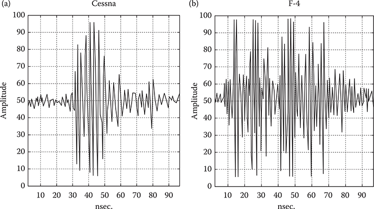
FIGURE 2.12
UWB Signal returns from (a) F-4 (large fighter aircraft) and (b) Cessna aircraft (small aircraft) with 1-ns pulse illumination. (Courtesy of D. Shriner.)
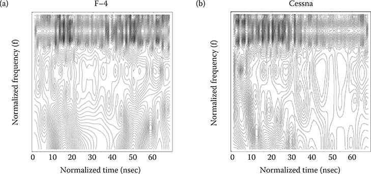
FIGURE 2.13
Time and frequency plots of (a) F-4 (large fighter aircraft) and (b) Cessna aircraft. UWB Radar returns after filtering with scaled wavelet packets. (From Barrett, T.W., Microwave J., 44, 2, 22-52, February, 2001b. Based on data from D. Shriner.)
A method for enhancing the designated target SNR in the presence of designated clutter, which also permits changes in the choice of designated target and clutter, was suggested by Barrett (1996)—the matched pulse or matched adaptive time-frequency packet (MAP) signal approach. The MAP method is a time-frequency approach and requires a priori information about the impulse response of the designated target or classes of target.
Figure 2.17 shows the general MAP procedure. Suppose a requirement exists to enhance the SNR selectively for two targets or classes of targets: target 1 and target 2. Further, suppose that the targets 1 and 2 will also serve to provide the target/clutter signal return for each other. That is, the choice of which is designated target and which is designated the clutter can be changed. (Figure 2.17a and b) using a UWB signal, for example, a monocycle, as the transmit pulse. The received signal in each case is treated as the impulse response of each target. These received signals are then time reversed to form their complex conjugate, and for purposes of exposition, they are called matched pulse 1 and matched pulse 2. Information concerning a target’s impulse response and thereby of its matched pulse constitutes a priori information about a target or class of targets.
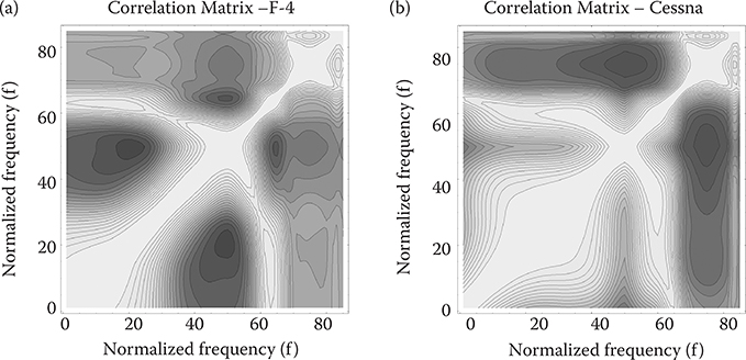
FIGURE 2.14
Frequency-Frequency correlation matrix (real values) across times of the values of a time-frequency analysis of (a) F-4 (large fighter aircraft) and (b) Cessna UWB signal returns. (From Barrett, T.W., Microwave J., 44, 2, 22-52, February, 2001b. Based on data from D. Shriner.)
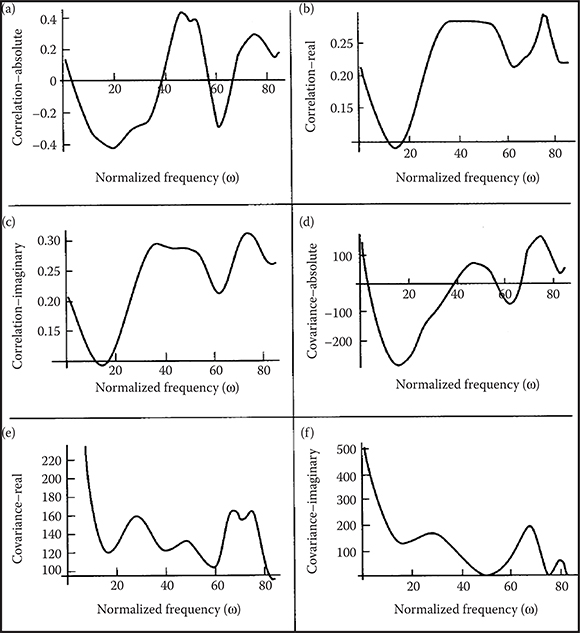
FIGURE 2.15
Correlations of the time content of the frequency bins and covariances of the time content of the absolute values of the wavelet packet time-frequency analysis for F-4 fighter aircraft returns (a, c, and e) and Cessna UWB signals (b, d, and f). (From Barrett, T.W., Microwave J., 44, 2, 22-52, February, 2001b. Based on data from D. Shriner.)
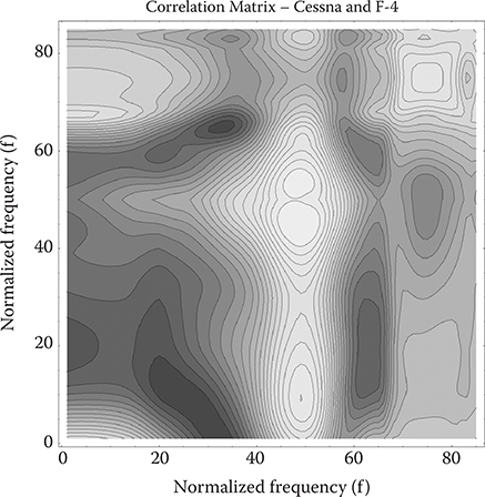
FIGURE 2.16
Frequency-Frequency correlation matrix (real values) across times of the values of a time-frequency analysis of Cessna and F-4 UWB signal returns. (From Barrett, T.W., Microwave J., 44, 2, 22-52, February, 2001b. Based on data from D. Shriner.)
In a second operational scenario (Figure 2.17c and d), the matched pulse for target 1 is transmitted and the return signal from targets 1 and 2 is received. Neglecting issues of the scattering matrix’s polarization and aspect dependence, according to systems theory the return signal from target 1 is enhanced (Figure 2.17c), and depending on the relative orthogonality of impulse response of target 2 with respect to that of target 1, the return signal from target 2 is diminished (Figure 2.17d). That is, the matched pulse 1 enhances the SNR of the signal return from target 1.
Conversely, in Figure 2.17e and f, the matched pulse for target 2 is transmitted and the return signal from targets 1 and 2 is received. Again, neglecting issues of the scattering matrix’s polarization and aspect dependence, according to systems theory the return signal from target 2 is enhanced (Figure 2.17e), and depending on the relative orthogonality of impulse response of target 1 with respect to that of target 2, the return signal from target 1 is diminished (Figure 2.17f). That is, the matched pulse 2 enhances the SNR of the signal return from target 2.
This method can be utilized to reduce clutter with resonances different from those of the target, to discriminate otherwise very similar targets or classes of targets on the basis of small differences between the targets’ scattering matrices, and to provide early warning of known threatening targets or classes of targets.
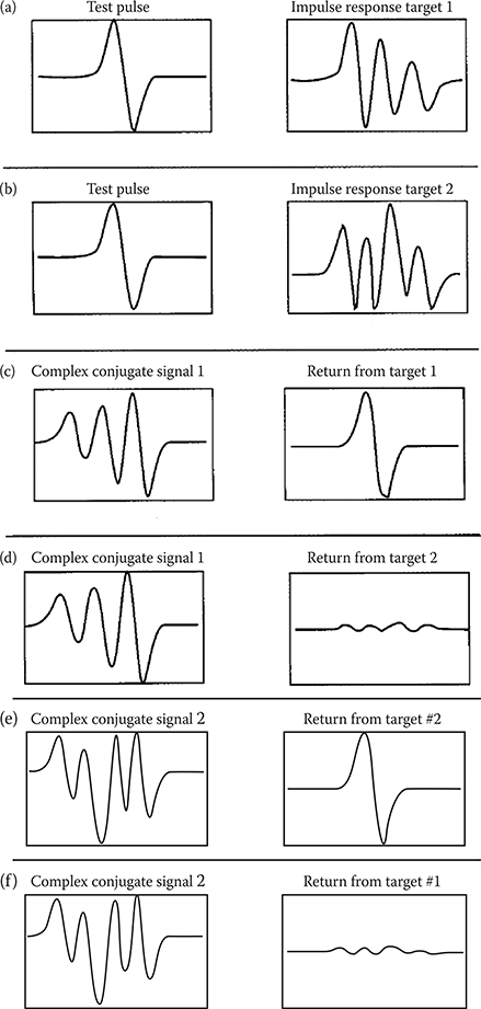
FIGURE 2.17
The MAP approach to high-resolution target detection with increase in target SNR and clutter rejection (a) A test pulse signal (left) is transmitted and a return signal (right) is received from target #1. (b) A test pulse signal (left) is transmitted and a return signal (right) is received from target #2. (c) The return pulse from target #1 is time reversed and transmitted to target #1 (left); a return signal is received from target #1 that is a close reconstruction of the test pulse transmitted in (a). (d) The return pulse from target #1 is time reversed and transmitted to target #2 (left); a return signal is received from target #2 that is much less than a reconstruction of the test pulse transmitted in (a), depending on the differences between target #1 and target #2. (e) The return pulse from target #2 is time reversed and transmitted to target #2 (left); a return signal is received from target #2 that is a close reconstruction of the test pulse transmitted in (b). (f) The return pulse from target #2 is time reversed and transmitted to target #1 (left); a return signal is received from target #1 that is much less than a reconstruction of the test pulse transmitted in (b), depending on the differences between target #1 and target #2. (Adapted from Barrett, T.W., Active Signaling Systems, U.S. Patent 5,486,833, January 23, 1996.)
2.10 Summary Observations about UWB Radar
A number of summary observations can be made concerning this historical account of the development of UWB radars/sensors. UWB radar systems have been in the commercial world since the 1970s. They have been successfully used in ground, wall, and foliage penetration; position location; warning for collision avoidance; fluid-level detection; intruder detection; and vehicle radar measurements. UWB radar is employed in SAR for FOPEN and ground mapping. Future planned applications include distance and air-bag proximity measurements and backup warning, road and runway inspection, breathing and heart monitoring, RF identification, and camera autofocus.
Conventionally, target identification is achieved by using a broadband signal to excite a target’s resonant frequencies, or for precise-range resolution by resolving all the major scatterers on the target. A swept frequency waveform can conceivably excite all of a target’s resonances; however, those excitations are over a period of time, which would preclude precise-range resolution. The UWB radar promises the achievement of both aims in a single system and a single-signal waveform.
Pulse power sources were discussed in Section 2.1. To achieve target detection/identification at substantial range, a UWB radar/sensor requires a transmitter to put sufficient energy on the target. A number of methods designed to illuminate the target with sufficient energy at substantial range have been proposed (cf. Taylor, 1995b; Noel, 1991). The proposed methods include arrays of emitters and trains of pulses in conjunction with correlation receivers. The antennas used or proposed for efficient transmission in UWB radar/sensor systems include loaded dipoles, TEM horns, biconicals, ridged horns, spiral, and the large-current antenna. All have merits and demerits.
The field of UWB radar/sensing, although still having a contentious history, has been less plagued—so far—with exaggerated performance claims in the public press, and invalid priority and originality claims, than has UWB communicati ons. The virtues of UWB radar/sensing are demonstrable and apparent, while the virtues of UWB communications remain obscure at this time.
Acknowledgments
Parts of this chapter originally appeared in the Progress in Electromagnetic Research Symposium 2000, Cambridge, MA, USA (PIERS 2000) (Barrett, 2000), and in the Microwave Journal, January and February 2001, History of Ultra Wideband Communications and Radar: Pioneers and Innovators, Parts I and II (Barrett, 2001a, 2001b).
Lieutenant Colonel James D. Taylor, USAF (Retired) who promoted the interests of the U.S. Department of Defense (DoD) in UWB radar during the 1980s, edited and updated the previous versions to help prepare this chapter.
References
Aiello, G., Rogerson, G.D. and Enge, P., Preliminary assessment of interference between ultra-wideband transmitters and the global positioning system: A cooperative study, Proc. January 2000 Natl. Tech. Meeting Institut. Navigation, Anaheim, CA, 2000.
Allen, B., Dahler, M., Okon, E.E., Malik, W.Q., Brown, A.K. and Edwards, D.J., Ultrawideband Antennas and Propagation for Communications, Radar and Imaging, Wiley, New York, 2007.
Andrews, J.R., Fast pulse generator survey. In Miller, E.K. (ed.), Time-Domain Measurements in Electromagnetics, Van Nostrand Reinhold, New York, pp. 95-121, 1986.
Astanin, L.Y., Analysis of electron current in a traveling wave field by beam velocity modulation (Russian), Vopr. Radioelectronici, 12, 34, 1964.
Astanin, L.Y., Ultrawideband signals—A new step in radar development, IEEE AES Syst. Mag., March, 12-15, 1992.
Astanin, L.Y. and Dorsky, Y., Russian Patent No. SU 1667512 A1, 1988.
Astanin, L.Y. and Kardo-Sysoev, A., personal communication, 2000.
Astanin, L.Y. and Kostylev, A.A., Principles of Superwideband Radar Measurements, (Russian) Moscow, Radio i Svyaz, 1989.
Astanin, L.Y. and Kostylev, A.A., Wideband signals—A new step in radar development, IEEE AES Syst. Mag., March, 12-15, 1992.
Astanin, L.Y. and Kostylev, A.A., Ultra-Wideband Radar Measurements: Analysis and Processing (Radar. Sonar, Navigation and Avionics Series), IEE, London, UK, 1997.
Astanin, L.Y., Kostylev, A.A., Zinoviev, Y.S. and Pasmurov, A.Y., Radar Target Characteristics: Measurements and Applications, CRC Press, Boca Raton, FL, 1994.
Astanin, L.Y., Chernyshov, E.E., Geppener, V.V., Jatzyn, A.S., Kostleva, V.V., Nicolaev, V.A., Sokolov, M.A., and Smirnov, A.B., Some problems in GPR soft- and hardware for improving mine detection and classification, Proc. of Euroem 2000 Conf., 30 May-2 June, Edinburgh, UK, 2000.
Auston, D.H., Picosecond optoelectronic switching and gating in silicon, Appl. Phys. Lett., 26, 101, 1975.
Auton, J.R. and Van Blaricum, M.L., Investigation of Procedures for Automatic Resonance Extraction from Noisy Transient Electromagnetics Data. ADA #104530, #104531, and #104532, August 17, 1981.
Barrett, T.W., The identification of nonlinear molecular systems by spectroscopic methods, Appl. Phys., 15, 213-218, 1978.
Barrett, T.W., Impulse (Time-Domain) Radar Technology Assessment Colloquium, W.J. Schafer Associates, Arlington, VA, 1988.
Barrett, T.W., Energy transfer and propagation, and the dielectrics of materials: Transient versus steady state effects. In Noel, B. (ed.), Ultra-Wideband Radar: Proceedings of the First Los Alamos Symposium, CRC Press, Boca Raton, FL, pp 1-19, 1991.
Barrett, T.W., Energy transfer through media and sensing of the media. In Taylor, J.D. (ed.), Introduction to Ultra-Wideband Radar Systems, CRC Press, Boca Raton, FL, pp. 365-434, 1995a.
Barrett, T.W., Performance prediction and modeling, In Taylor, J.D. (ed.), Introduction to Ultra- Wideband Radar Systems, CRC Press, Boca Raton, FL, pp. 609-656, 1995b.
Barrett, T.W., Active Signaling Systems, U.S. Patent 5,486,833, January 23, 1996.
Barrett, T.W., History of ultrawideband (UWB) radar & communications: Pioneers and innovators, Prog. Electromagn. Symp. 2000 (PIERS2000), Cambridge, MA, p. 366, July 2000.
Barrett, T.W., History of ultrawideband (UWB) communications & radar: Pioneers and innovators: Part 1, UWB Communications, Microwave J., 44, 1, 22-56, January, 2001a.
Barrett, T.W., History of ultrawideband (UWB) communications & radar: Pioneers and innovators: Part 2, UWB radars & sensors, Microwave J., 44, 2, 22-52, February, 2001b.
Baum, C.E., On the singularity expansion method for the solution of electromagnetic interaction problems, Air Force Weapons Laboratory, Interaction Note 88, December, 1971.
Baum, C.E., Emerging technology for transient and broad-band analysis and synthesis of antennas and scatterers, Proc. IEEE, 64, 1598-1616, 1976.
Baum, C.E., Carin, L. and Stone, A.P. (eds.), Ultra-Wideband, Short-Pulse Electromagnetics 3, Plenum Press, New York, 1997.
Bennett, C.L. and Ross, G.F., Time-domain electromagnetics and its application, Proc. IEEE, 66, 299-318, 1978.
Bertoni, H.L., Carin, L. and Felsen, L.B. (eds.), Ultra-Wideband Short-Pulse Electromagnetics, Plenum Press, New York, 1993.
Black, H.S., Beyer, J.W., Grieser, T.J. and Polkinghorn, F.A., A multichannel microwave radio relay system, AIEE Trans. Elect. Eng., 65, 798-805, 1946.
Borisov, V. and Utkin, A., Transient electromagnetic field produced by a moving pulse of line current, J. Phys. D: Appl. Phys., 28, 614-622, 1995 (English).
Bunkin, B. and Kashin, V. Distinctive features, problems and perspectives of subnanosecond radar video pulses (Russian), Radiotechnica, 4-5, 128-133, 1995.
Carin, L. and Felsen, L.B. (eds.), Ultra-Wideband Short-Pulse Electromagnetics 2, Plenum Press, New York, 1995.
Chernousov, V., Dispersion of nonharmonic electromagnetic waves in ideally conducting bodies of finite size, (Russian) Radiotechnology and Electronics (Russian Academy Magazine), 8, 31-39, 1965a.
Chernousov, V., Nonstationary radiation of antenna systems, (Russian) Radiotechnology and Electronics (Russian Academy Magazine), 1, 1446-1452, 1965b.
Chernousov, V., Dispersion of ideally conducting nonharmonic electromagnetic waves in the Kirchhoff approximation, (Russian) Radiotechnology and Electronics (Russian Academy Magazine), 10, 1750-1756, 1969.
Cheville, R.A. and Grischkowsky, D., Time domain terahertz impulse ranging studies, Appl. Phys. Lett., 67, 1960-1962, 1995.
Cheville, R.A. and Grischkowsky, D., Late time target response measured with THz impulse ranging, IEEE Trans. Antennas Propag., 45, 1518-1524, 1997.
Cook, C.E. and Bernfeld, M., Radar Signals: An Introduction to Theory and Application, Academic Press, New York, 1967.
Cronson, H., Picosecond pulse sequential waveform generation, Proc. IEEE, 1975 MTS Int. Symp., 185-186, 1975.
Daniels, D.J., Short-pulse radar for stratified lossy dielectric layer measurement, IEEE Proc. F. Commun., Radar and Signal Process., 127, 384-388, 1980.
Daniels, D.J., Gunton, D.J. and Scott, H.F., Introduction to subsurface radar, IEEE Proc. F. Commun, Radar and Signal Process, 135, 278-320, 1988.
De Loor, G.P., The dielectric properties of wet materials, IEEE Trans., GE-21, 364-369, 1983.
De Rosa, L.A., Random Impulse System, U.S. Patent 2,671,896, 1954.
Didenko, A.N. and Novikov, S.A., Forming of high power UWB radio signals by series compression, (Russian) Proc. Academy of Sci., 321, 518-520, 1991.
Dixon, R.C., Spread Spectrum Systems, Wiley, New York, 1984.
Edwards, R.N., Carey, W.J. and Nunnally, W.C., Compact, ultrawideband, impulse generators for electro-optical applications. In Carin, L. and Felsen, L.B. (eds.), Ultra-Wideband Short-Pulse Electromagnetics 2, Plenum Press, New York, pp. 41-49, 1995.
Efanov V., Kardo-Sysoev A. and Jarin P., High-voltage semiconductor generator of rectangular pulses with controllable duration (Russian), Devices Exp. Tech. 4, pp. 38-50, 1997.
Efimchik, M.I. and Levitas, B.N., Transients in waveguide, Radiotekhnika i Elektronika, 21, 691-700, 1976.
Elachi, C., Roth, L.E. and Schaber, G.G., Spaceborne radar subsurface imaging in hyperarid regions, IEEE Trans, GE-22, 383-388, 1984.
Evans, S. and Kong, F.N., Gain and effective area for impulse antennas, 3rd Int. Conf. Antennas and Propagation, April, 421-424, 1983a.
Evans, S. and Kong, F.N., TEM horn antennas: Input reflection characteristics in transmission, IEE Proc. H. Microwaves, Antennas and Propag., 130, 403-409, 1983b.
Fano, R.M., Signal-to-noise ratios in correlation detectors, MIT Research Lab Electronics Tech. Rept., 186, February 19, 1951.
Federal Communications Commission (FCC), United States. Notice of Proposed Rule Making (NPRM) FCC 00-163, ET Docket 98-153, In the matter of Revision of Part 15 of the Commission’s Rules Regarding Ultra-Wideband Transmission Systems, Adopted May 10, 2000; Released May 11, 2000.
Feld, Ya., Theorems and problems associated with transient phenomena in electromagnetics, Doklady Academy of Sciences USSR, 318 No 2, 1991 (Russian).
Fink, D.G. and Christiansen, D. (eds.), Electronics Engineers’ Handbook, McGraw-Hill, New York, 1975.
Fink, D.G. and Christiansen, D. (eds.), Electronics Engineers Handbook. McGraw-Hill, New York, 1997.
Finkelstein, M. (ed.), Subsurface radar, Radio i Svjaz, Moscow, 1994 (Russian).
George, S.F., Effectiveness of crosscorrelation detectors, Proc. National Electronics Conf. (Chicago) 10, 109-118, 1954.
Glebovich, G.V., Andriyanov, A.V., Vvedenskij, V., Kovalev, I.P., Krylov, V.V. and Ryabinin, A., Study of Objects Using Picosecond Pulses, Moscow, Radio i Svyaz’, 1984.
Green, P.I., The output signal-to-noise ratio of correlation detectors, IRE Trans, IT-3, 10-18, 1957.
Grekhov, I.V., Kardo-Sysoev, A.F., Kostina, L.S. and Shenderey, S.V., High-power sub- nanosecond switch, Electron. Lett. 17, 422, 1981.
Grekhov, I.V., Efanov, V.M., Kardo-Sysoev, A.F. and Smirnova, I.A., Subnanosecond semiconductor power switches with long “on” time, Sov. Tech. Phys. Lett., 11, 372-3373, 1985.
Harmuth, H.F., Transmission of Information by Orthogonal Functions, First Edition, Springer, New York, 1969.
Harmuth, H.F., Transmission of Information by Orthogonal Functions, Second Edition, Springer, New York, 1972a.
Harmuth, H.F., Signal Processing and Transmission by Means of Walsh Functions, U.S. Patent 3,678,204, July 18, 1972b.
Harmuth, H.F., Sequency Filters Based on Walsh Functions for Signals with Two Space Variables, U.S. Patent 3,705,981, December 12, 1972c.
Harmuth, H.F., Range-Doppler resolution of electromagnetic Walsh waves in radar, IEEE Trans. Electromagn. Compat., EMC-17, 106-1111, 1975.
Harmuth, H.F., Selective reception of periodic electromagnetic waves with general time variation, IEEE Trans. Electromagn. Compat., EMC-19, 137-1144, 1977a.
Harmuth, H.F., Sequency Theory, Academic Press, New York, 1977b.
Harmuth, H.F., Synthetic aperture radar based on nonsinusoidal functions. II. Pulse compression, contrast, resolution, and Doppler shift, IEEE Trans. Electromagn. Compat., EMC-21, 40-449, 1979.
Harmuth, H.F., Synthetic aperture radar based on nonsinusoidal functions. VI. Pulse position and pulse shape coding, IEEE Trans. Electromagn. Compat., EMC-22, 93-9106, 1980.
Harmuth, H.F., Nonsinusoidal Waves for Radar and Radio Communication, Academic Press, New York, 1981.
Harmuth, H.F., Antennas and Waveguides for Nonsinusoidal Waves, Academic Press, New York, 1984.
Harmuth, H.F., Radiation of Nonsinusoidal Electromagnetic Waves, Academic Press, New York, 1990.
Harmuth, H.F., Transmitter signature and target signature of radar signals. In Taylor, J.D. (ed.), Introduction to Ultra-Wideband Radar Systems, CRC Press, Boca Raton, FL, pp. 435-4456, 1995.
Heyman, E. and Mandelbaum, B. (eds.), Ultra-Wideband Short-Pulse Electromagnetics 4, Plenum Press, New York, 1999.
Hoekstra, P. and Delaney, A., Dielectric properties of soils at UHF and microwave frequencies, J. Geophys. Res., 79, 1699-11708, 1979.
Hoeppner, C.H., Pulse Communication System, U.S. Patent 2,999,128, September 5, 1961.
Hopkins, J.M. and Sibbett, W., Ultrashort pulse lasers: Big payoffs in a flash, Sci. Am., 283, 72-779, 2000.
Horton, B.M., Noise-modulated distance measuring systems, Proc. IRE, 47, 821-8828, 1959.
Immoreev, I., Use of ultra-wideband location in air defense (Russian), Questions of Special Radio Electronics—Series Radar Engineering, 22, 76-783, 1991.
Immoreev, I., Ultra-wideband radars: Main features and dissimilarities with conventional radars (Russian), Electromag. Waves Electron. Syst. (Russian Academy Magazine), 2, N1, 81-888, 1997.
Immoreev, I., Ultra-wideband radars: New opportunities, uncommon problems, system features (Russian), Proc. Bauman Moscow State Tech. Univ., V.4, 25-256, 1998.
Immoreev, I. and Fedotov, D., Optimum processing of radar signals with unknown parameters, (Russian) Radiotechnica, 10, 84-888, 1998.
Immoreev, I. and Teliatnikov, L., Energy efficiency of sounding pulse in ultra-wideband radar (Russian), Radiotechnica, 9, 37-348, 1997.
Immoreev, I. and Zivlin, V., Moving target indication in radars with the ultra-wideband sounding signal (Russian), Questions of Special Radio Electronics—Series Radar Engineering, 3, 1992.
Jayarman, S. and Lee, C.H., Observation of two-photon conductivity in GaAs with nanosecond and picosecond light pulses, Appl. Phys. Lett., 20, pp. 392-3395, 1972.
Jouny, I.I. and Walton, E.K., Target identification using bispectral analysis of ultra-wideband radar data. In Noel, B. (ed.), Ultra-Wideband Radar: Proceedings of the First Los Alamos Symposium, CRC Press, Boca Raton, FL, pp. 405-4416, 1991.
Kharkevitch, A., Transient Wave Phenomena, Nauka, Moscow, (Russian) 1952.
Kardo-Sysoev, A.F., Reshetin, V.P., Tchashnikov, I.G., and Shuman, V.B., Avalanche injection in highspeed thyristors. IEEE Trans. Electron. Devices, 23, 1203-11207, 1976.
Kardo-Sysoev, A., Ultra-Wideband Electrodynamics, Ioffe Physics and Technical Institute Press, St. Petersburg, Russian Federation, 1997.
Kennaugh, E.M. and Moffatt, D.L., Transient and impulse response approximations, Proc. IEEE, 893901, 1965.
Kim, A.H., Didomenico, L.D., Jasper, L.J., Youmans, R.J. and Koscica, T.E., Ultrawideband High Power Photon Triggered Frequency Independent Radiator, U.S. Patent 5,227,621, July 13, 1993.
King, R.W.P. and Smith, G.S., Antennas in Matter: Fundamentals, Theory, and Applications, MIT Press, Cambridge, MA, 1981.
Kingsley, L.E., Weiner, M., Kim, A., Pastore, R., Youmans, R.J. and Singh, H. In Carin, L. and Felsen, L.B. (eds.), Ultrafast switching at the U.S. Army Pulse Power Center. In Ultra-Wideband Short-Pulse Electromagnetics 2, Plenum press, New York, pp. 85-896, 1995.
Kononov, A., Applications of tomographic methods for radar imaging using ultra-wideband signals, Zarubezn. Radioelectronica, Moscow, 12, 512-5526, 1992 (Russian).
Kostylev, A., Identification of radar targets using UWB signals: Methods and Applications, Zarubezn. Radioelectronica, 4, 78-781, 1984 (Russian).
Kostylev, A.A., Astain, L. Yu., Zinoviev, J.S. and Pasmurov, A. Ya., “Radar Characteristics of Aircraft”, CRC Press, Boca Raton, FL, 1994.
Krymscy, V., Bucharin V. and Zaliapin V., Theory of Nonsinusoidal Waves (Russian), Cheliabinsk State Technical University Press, Russian Federation, 1995.
Lahaie, I.J. (ed.), Ultrawideband radar: Proceedings 22-23 January 1992, SPIE Proc. Ser., 1631, 1992.
Lee, C.H. (ed.), Picosecond Optoelectronic Devices, Academic Press, New York, 1984.
Lee, Y.W., Application of statistical methods to communication problems, MIT Research Lab. Electronics. Rept., September 1, 181, 1950.
Lee, Y.W., Statistical Theory of Communication, Wiley, New York, 1960.
Lee, Y.W. and Wiesner, J.B., Correlation functions and communication applications, Electronics, 23, 86-892, 1950.
Lee, Y.W., Selected Papers of Norbert Wiener, MIT Press, Cambridge, MA, pp. 17-133, 1964.
Lee, Y.W. and Schetzen, M., Measurement of the Wiener kernels of a nonlinear system by cross-correlation, Int. J. Control, 2, 237-2254, 1965.
Loubriel, G.M., Zutavern, F.J., Denison, G.J., Helgeson, W.D., McLaughlin, D.L., O’Malley, M.W. and Demarest, J.A., Photoconductive semiconductor switches for high power radiation. In Bertoni, H.L., Carin, L. and Felsen, L.B. (eds.), Ultra-Wideband Short-Pulse Electromagnetics, Plenum Press, New York, pp. 29-236, 1993.
Loubriel, G.M., Zutavern, F.J., O’Malley, M.W., Gallegos, R.R. and Helgeson, W.D., The use of optically triggered, high-gain GaAs switches for ultra-wideband pulse generation. In Carin, L. and Felsen, L.B. (eds.), Ultra-Wideband, Short-Pulse Electromagnetics 2, Plenum Press, New York, pp. 33-339, 1995.
Malmstadt, H.V. and Enke, C.G., Electronics for Scientists, Benjamin, New York, 1963.
Marmarelis, P.Z . and Marmarelis, V.Z., Analysis of Physiological Systems: The White Noise Approach, Plenum Press, New York, 1978.
Marmarelis, V.Z. and Sheby, D., Evolutionary enhancements of broadband radars for improved stealth surveillance, low probability of intercept, and covert communications capabilities. In Barrett, T.W., Impulse (Time-Domain) Radar Technology Assessment Colloquium, W.J. Schafer Associates, Arlington, VA, March 16-117, 1988.
Marmarelis, V.Z., Sheby, D., Kisenwether, E.C. and Erdley, T.A., High-order signal processing for ultra-wideband radar signals. In Taylor, J.D. (ed.), Introduction to Ultra-Wideband Radar Systems, CRC Press, Boca Raton, FL, pp. 579-5607, 1995.
McEwan, T.E., Ultra-Wideband Radar Motion Sensor, U.S. Patent 5,361,070, 1994.
McEwan, T.E., Reexamination Certificate (4084th) B1 5,361,070, Certificate Issued May 16, 2000.
Meleshko, E.A., Nanosecond Electronics in Experimental Physics, Ehnergoatomizdat Press, Moscow, 1987.
Miller, E.K. (ed.), Time-Domain Measurements in Electromagnetics, Van Nostrand Reinhold, New York, 1986.
Moffatt, D.L. and Mains, R.K., Detection and discrimination of radar targets, IEEE Trans. Antennas Propag., AP-23, 358-3367, 1975.
Moffatt, D.L. and Puskar, R.J., A subsurface electromagnetic pulse radar, Geophysics, 41, 506-5518, 1976.
Morey, R.N., Geophysical Survey System Employing Electromagnetic Impulses, U.S. Patent 3,806,795, 1974.
Morgan, M.A., Singularity expansion representation of fields and currents in transient scattering, IEEE Trans. Antennas Propag., AP-32, 466-4473, 1984.
Mourou, G. and Knox, W., High power switching with picosecond precision, Appl. Phys. Lett., 35, 492-4495, 1979.
Naidenov, A., Spectrum Transformation of Nanosecond Pulse Transmitters, Nauka, Moscow, 1978 (Russian).
Noel, B., (ed.), Ultra-Wideband Radar: Proceedings of the First Los Alamos Symposium, CRC Press, Boca Raton, FL, 1991.
Nunnally, W.C. and Edwards, R.N., Generation and radiation of high power impulses for wideband radar systems. In Noel, B. (ed.), Ultra-Wideband Radar: Proceedings of the First Los Alamos Symposium, CRC Press, Boca Raton, FL, pp. 217-2226, 1991.
OSD/DARPA, Assessment of Ultra-Wideband (UWB) Technology, Ultra-Wideband Radar Review Panel, R-6280, Office of the Secretary of Defense, Defense Advanced Research projects Agency, July 13, 1990.
Osipov M. Ultra-wideband radar (Russian), Radiotechnica, 3, 3-6, 1995.
Osumi, N. and Ueno, K., Detection of buried plant, IEE Proc. F. Commun, Radar and Signal Process. 135, pp. 330-3342, 1988.
Oswald, G.K.A., Geophysical radar design, IEE Proc. F., Comm. Radar and Signal Process., 135, 371-3379, 1988.
Pearson, L.W., A note on the representation of scattered fields as a singularity expansion, IEEE Trans. Antennas Propag., AP-32, 520-5524, 1984.
Pittman, W.E., Church, R.H., Webb, W.E. and McLendon, J.T., Ground penetrating radar: A review of its use in the mining industry, U.S. Bureau of Mines, Information Circular No. 8964, 1982.
Platts, D., Gigawatt Marx Bank Pulsers. In Noel, B. (ed.), Ultra-Wideband Radar: Proceedings of the First Los Alamos Symposium, CRC Press, Boca Raton, FL, pp. 241-2245, 1991.
Platts, D., Zucker, O.S.F. and McIntyre, I.A., Transmitters. In Taylor, J.D. (ed.), Introduction to Ultra-Wideband Radar Systems, CRC Press, Boca Raton, FL, pp. 109-1144, 1995.
Pocha, M.D., Druce, R.L. and Griffin, K.L., Subnanosecond photoconductive switching in GaAs. In Noel, B. (ed.), Ultra-Wideband Radar: Proceedings of the First Los Alamos Symposium, CRC Press, Boca Raton, FL, pp. 229-2239, 1991.
Raemer, H.R. and Reich, A.B., Correlation devices detect weak signals, Electronics, 32, 58-560, 1959.
Robbins, K.W., Short Baseband Pulse Receiver, U.S. Patent 3,662,316, May 9, 1972.
Robbins, K.W. and Robbins, G.F., Stable Base-Band Superregenerative Selective Receiver, U.S. Patent 3,794,996, February 26, 1974.
Rosen, A. and Zutavern, F. (eds.), High-Powered Optically Activated Solid State Switches, Artech House, Boston, 1994.
Ross, G.F., A time domain criterion for the design of wideband radiating elements, IEEE Trans. Antennas Propag., 16, 355, 1968.
Ross, G.F., Transmission and Reception System for Generating and Receiving Base-Band Duration Pulse Signals for Short Base-Band Pulse Communication System, U.S. Patent 3,728,632, April 17, 1973a.
Ross, G.F., Energy Amplifying Selector Gate for Base-Band Signals, U.S. Patent 3,750,025, July 31, 1973b.
Ross, G.F., Early developments and motivations for time-domain analysis and application. In Miller, E.K. (ed.), Time-Domain Measurements in Electromagnetics, Van Nostrand Reinhold, New York, pp. 1-44, 1986.
Ross, G.F. and Lamensdorf, D., Balanced Radiator System, U.S. Patent 3,659,203, April 25, 1972.
Ross, G.F. and Mara, R.M., Coherent processing tunnel diode ultra wideband receiver, U.S. Patent 5,337,054, August 9, 1994.
Ross, G.F. and Robbins, K.W., Base-Band Radiation and Reception System, U.S. Patent 3,739,392, June 12, 1973.
Ross, G.F. and Robbins, K.W., Narrow Range-Gate Baseband Receiver, U.S. Patent 4,695,752, September 22, 1987.
Rudnick, P., The detection of weak signals by correlation methods, J. Appl. Phys., 24, 128-1131, 1953.
Safar, M.H., On the lateral resolution achieved by Kirchhoff migration, Geophysics, 50, 1091-11099, 1985.
Sarkar, T., Adve, R. and Wicks, M., Photoconductive switching-revisited. In Bertoni, H.L., Carin, L. and Felsen, L.B. (eds.), Ultra-Wideband Short-Pulse Electromagnetics, Plenum Press, New York, pp. 51-555, 1993.
Schneider, W.A., Integral formulation for migration in two and three dimensions, Geophysics, 43, 49-476, 1978.
Shantz, H., The Art and Science of Ultrawideband Antennas, Artech House, Norwood, MA, 2005.
Shatz, S., Transistors in Pulse Technology, Sudgiz, Leningrad, 1963.
Shirman, Y.D., Leshchenko, S.P., and Orlenko, V.M., On the first domestic investigation of UWB radar,” Radiotechnika, 1, 891-8905, 1991 (Russian).
Singleton, H.E., A digital electronic correlator, Proc. IRE, 138, 1422-11428, 1950.
Skolnik, M.I., Introduction to Radar Systems, 1st Edition, McGraw-Hill Book Co., New York, 1962.
Smith, R.J., Circuits, Devices and Systems, Wiley, New York, 1966.
Smith, G.S., Directive properties of antennas for transmission into a material half-space, IEEE Trans., AP-32, 1018-11026, 1984.
Sobol, H., Microwave communications—An historical perspective, IEEE Trans. Microwave Theory Tech., MTT-32, 1170-11181, 1984.
Sodin, L., Pulsed antenna radiation: electromagnetic missile (Russian), Radiotechnology and Electronics (Russian Academy Magazine), 5, 1014-11022, 1991.
Sodin, L., Characteristics of pulsed antenna radiation: Electromagnetic missile (Russian), Radiotechnology and Electronics (Russian Academy Magazine), 5, 849-8857, 1992.
Stryukov, B., Lukyannikov, A., Marinetz, A. and Feodorov, N., Short impulse radar systems (Russian), Zarubezhnaya Radioelectonika, 8, 42-459, 1989.
Susman, L. and Lamensdorf, L., Picosecond pulse antenna techniques, Rome Air Development Center, Rep. TR-71-64, AD 884646, May, 1971.
Taylor, J.D. (ed.), Introduction to Ultra-Wideband Radar Systems, CRC Press, Boca Raton, FL, 1995a.
Taylor, J.D., Ultra-wideband radar overview. In Taylor, J.D. (ed.), Introduction to Ultra-Wideband Radar Systems, CRC Press, Boca Raton, FL, pp. 1-10, 1995b.
Taylor, J.D., Ultrawideband Radar Technology, CRC Press, Boca Raton, FL, 2000.
Taylor, J.D. and Kisenwether, E.C., Ultra-wideband radar receivers. In Taylor, J.D. (ed.), Introduction to Ultra-Wideband Radar Systems, CRC Press, Boca Raton, FL, pp. 491-4577, 1995.
Tektronix, Inc., Instruction Manual: Type S-2 Sampling Head, S.W. Millikan Way, P.O. Box 500, Beaverton, Oregon 97005, 1968.
Theodorou, E.A., Gorman, M.R., Rigg, P.R. and Kong, F.N., Broadband pulse-optimised antenna, IEE Proc. H. Microwaves, Antennas and Propag., 128, 124-1130, 1981.
Tikhonov, A.N. and Arsenin, V., Methods for Solving Ill-Posed Problems, Nauka, Moscow, 1986 (Russian).
Tikhonov, A.N. and Goncharsky, A.V. (eds.), Ill-Posed Problems in the Natural Sciences, MIR, Moscow, 1987 (English).
Ulriksen, C.P.F., Application of Impulse Radar to Civil Engineering, Doctoral Thesis, Lund University of Technology, Department of Engineering Geology, Lund, Sweden, 1982.
Vainshtein, S.H., Zhilyaev, Y.V. and Levinstein, M.E., Visualization of sub-nanosecond switching of gallium arsenide diode structures, Sov. Tech. Phys. Lett., 14, 664-6665, 1988.
Van Blaricum, M.L., Problems and solutions associated with Prony’s method for processing transient data, IEEE Trans. Antennas Propag. AP-26, 174-1182, 1978.
Van Blaricum, M.L., A view of the early-time component in impulse scattering. In Noel, B. (ed.), Ultra-Wideband Radar: Proceedings of the First Los Alamos Symposium, CRC Press, Boca Raton, FL, pp. 191-1202, 1991.
Van Blaricum, M.L., Radar cross section and target scattering. In Taylor, J.D. (ed.), Introduction to Ultra-Wideband Radar Systems, CRC Press, Boca Raton, FL, pp. 457-4490, 1995.
Van Blaricum, M.L. and Mittra, R., A technique for extracting the poles and residues of a system directly from its transient response, IEEE Trans. Antennas and Propag., AP-23, 777-7781, 1975.
van Etten, P., The present technology of impulse radars, Int. Radar Conf. Proc., 535-5539, October 1977.
Varganov, M.E., Zinov’ev, Y.S., Astanin, L. Ya., Kostylev, A.A., Sarychev, V.A., Siezkinskij, S.K. and Dmitriev, B.D., Radar Response of Flight Vehicles, Radio I Svyaz’, Moscow, 1985.
Vickers, R.S. (ed.), Ultrahigh resolution radar, SPIE Proc., 1631, 1992.
Volterra, V., Theory of Functionals and of Integral and Integro-Differential Equations, Dover Publications, New York, 1959.
Wicks, M.C. and van Etten, P., Orthogonally Polarized Quadraphase Electromagnetic Radiator, U.S. Patent 5,068,671, November 26, 1991.
Wiener, N., Response of a nonlinear device to noise, Report No 129, Radiation Laboratory, MIT, Cambridge. MA, 1942.
Wiener, N., Nonlinear Problems in Random Theory, MIT Press, Cambridge, MA, 1958.
Wohlers, R.J., The GWIA, an extremely wide bandwidth low-dispersion antenna, Abstracts 20th Symp. USAF Antenna R & D Prog., October, 1970.
Yeung, W.K. and Evans, S., Time-domain microwave target imaging, IEE Proc. F. Commun, Radar and Signal Process., 135, 345-3350, 1988.
Yushkov, Y. and Badulin, N.N., A nanosecond pulse-compression microwave radar, Electromagnet. Waves and Electron. Syst. (Russian), 2, 26-230, 1997.
Zernov, N., On the solution of transient boundary problems in electrodynamics (Russian), Dokl. Akad. Nauk USSR, 30, 1269-11278, 1951.
Zernov N. and Merkulov G., Energy characteristics of aperture antennas: Radiating nonharmonical waves (Russian), Radiotechnica, 1, 68-671, 1991a.
Zernov N. and Merkulov G., Antennas in a mode of radiation (reception) of ultra-wideband signals (Russian), Zarubezhnaya Radioelectronika, 1, 84-894, 1991b.