
Z-buffer: Bringing Order into Chaos
What is a z-buffer? In Chapter 4, we discussed the framebuffer. It stores the color for each pixel on the screen. When OpenGL ES renders a triangle to the framebuffer, it just changes the color of the pixels that make up that triangle.
The z-buffer is very similar to the framebuffer in that it also has a storage location for each pixel on the screen. Instead of storing colors, it stores depth values. The depth value of a pixel is roughly the normalized distance of the corresponding point in 3D to the near clipping plane of the view frustum.
OpenGL ES will write a depth value for each pixel of a triangle to the z-buffer by default (if a z-buffer was created alongside the framebuffer). All you have to tell OpenGL ES is to use this information to decide whether a pixel being drawn is closer to the near clipping plane than the one that's currently there. For this, you just need to call glEnable() with an appropriate parameter:
GL10.glEnable(GL10.GL_DEPTH_TEST);
That's all you need to do. OpenGL ES will then compare the incoming pixel depth with the pixel depth that's already in the z-buffer. If it is smaller, it is also closer to the near clipping plane and thus in front of the pixel that's already in the frame- and z-buffer.
Figure 10–5 illustrates the process. The z-buffer starts off with all values set to infinity (or a very high number). When you render the first triangle, compare each of its pixels' depth values to the value of the pixel in the z-buffer. If the depth value of a pixel is smaller than the value in the z-buffer, it passes the so-called depth test, or z-test. The pixel's color will be written to the framebuffer, and its depth will overwrite the corresponding value in the z-buffer. If it fails the test, neither the pixel's color nor the depth value will be written to the buffers. This is shown in Figure 10–6, where the second triangle is rendered. Some of the pixels have smaller depth values and thus get rendered; other pixels don't pass the test.
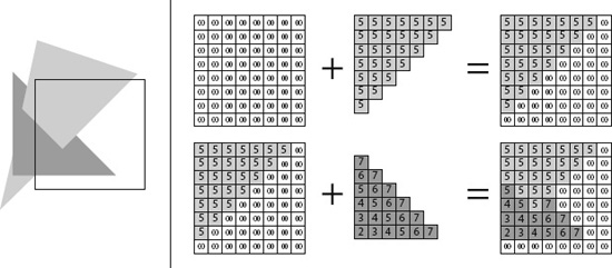
Figure 10–6. Image in the framebuffer (left); z-buffer contents after rendering each of the two triangles (right).
As with the framebuffer, we also have to clear the z-buffer for each frame, otherwise the depth values from the last frame would still be in there. To do this, call glClear(), as per the following:
gl.glClear(GL10.GL_COLOR_BUFFER_BIT | GL10.GL_DEPTH_BUFFER_BIT);
This will clear the framebuffer (or colorbuffer) as well as the z-buffer (or depthbuffer), all in one go.
Fixing the Last Example
Let's fix the last example's problems by using the z-buffer. You just copied all the code over to a new class called ZBufferTest, and you modified the present() method of the new ZBufferScreen class, as shown in Listing 10–4.
Listing 10–4. Excerpt from ZBufferTest.java: Using the Z-buffer.
@Override

public void present(float deltaTime) {

    GL10 gl = glGraphics.getGL();

    gl.glClear(GL10.GL_COLOR_BUFFER_BIT | GL10.GL_DEPTH_BUFFER_BIT);

    gl.glViewport(0, 0, glGraphics.getWidth(), glGraphics.getHeight());

    gl.glMatrixMode(GL10.GL_PROJECTION);

    gl.glLoadIdentity();

    GLU.gluPerspective(gl, 67,

            glGraphics.getWidth() / (float)glGraphics.getHeight(),

            0.1f, 10f);

    gl.glMatrixMode(GL10.GL_MODELVIEW);

    gl.glLoadIdentity();


    gl.glEnable(GL10.GL_DEPTH_TEST);


    vertices.bind();

    vertices.draw(GL10.GL_TRIANGLES, 0, 6);

    vertices.unbind();


    gl.glDisable(GL10.GL_DEPTH_TEST);

}
The first thing changed is the arguments to the call to glClear(). Now both buffers are cleared instead of just the framebuffer.
You must also enable depth-testing before rendering the two triangles. After you are done with rendering all of the 3D geometry, you must disable depth-testing again. Why? Imagine that you want to render 2D UI elements on top of your 3D scene, like the current score or buttons. Since you'd use the SpriteBatcher for this, which only works in 2D, you wouldn't have any meaningful z-coordinates for the vertices of the 2D elements. You wouldn't need depth-testing either, since you would explicitly specify the order in which you want the vertices to be drawn to the screen.
The output of this example, shown in Figure 10–7, looks as expected now.

Figure 10–7. The z-buffer in action, making the rendering order-independent.
Finally, the green triangle in the middle is rendered correctly behind the red triangle, thanks to our new best friend, the z-buffer. As with most friends, however, there are times when your friendship suffers a little from minor issues. Let's examine some caveats when using the z-buffer.
Blending: There's Nothing Behind You
Assume that you want to enable blending for the red triangle at z = −3 in your scene. Say you set each vertex color's alpha component to 0.5f, so that anything behind the triangle shines through. In this case, the green triangle at z = −5 should shine through. Let's think about what OpenGL ES will do and what else will happen:
- OpenGL ES will render the first triangle to the z-buffer and colorbuffer.
- Next OpenGL ES will render the green triangle because it comes after the red triangle in our
Vertices3instance. - The portion of the green triangle behind the red triangle will not get shown on the screen due to the pixels being rejected by the depth test.
- Nothing will shine through the red triangle in the front since nothing was there to shine through when it was rendered.
When using blending in combination with the z-buffer, you have to make sure that all transparent objects are sorted by increasing the distance from the camera position and rendering them back to front. All opaque objects must be rendered before any transparent objects. The opaque objects don't have to be sorted, though.
Let's write a simple example that demonstrates this. Keep your current scene composed of two triangles and set the alpha component of the vertex colors of the first triangle (z = −3) to 0.5f. According to our rule, you have to first render the opaque objects—in this case the green triangle (z = −5)—and then all the transparent objects, from furthest to closest. In this scene, there's only one transparent object: the red triangle.
Copy over all the code from the last example to a new class called ZBlendingTest and rename the contained ZBufferScreen to ZBlendingScreen. All you need to do is change are the vertex colors of the first triangle, and enable blending and rendering the two triangles in order in the present() method. Listing 10–5 shows the two relevant methods.
Listing 10–5. Excerpt from ZBlendingTest.java: Blending with the Z-buffer Enabled.
public ZBlendingScreen(Game game) {

    super(game);


    vertices = new Vertices3(glGraphics, 6, 0, true, false);

    vertices.setVertices(new float[] { -0.5f, -0.5f, -3, 1, 0, 0, 0.5f,

                                        0.5f, -0.5f, -3, 1, 0, 0, 0.5f,

                                        0.0f,  0.5f, -3, 1, 0, 0, 0.5f,

                                        0.0f,  -0.5f, -5, 0, 1, 0, 1,

                                        1.0f,  -0.5f, -5, 0, 1, 0, 1,

                                        0.5f,  0.5f, -5, 0, 1, 0, 1}, 0, 7 * 6);

}


@Override

public void present(float deltaTime) {

    GL10 gl = glGraphics.getGL();

    gl.glClear(GL10.GL_COLOR_BUFFER_BIT | GL10.GL_DEPTH_BUFFER_BIT);

    gl.glViewport(0, 0, glGraphics.getWidth(), glGraphics.getHeight());

    gl.glMatrixMode(GL10.GL_PROJECTION);

    gl.glLoadIdentity();

    GLU.gluPerspective(gl, 67,

            glGraphics.getWidth() / (float)glGraphics.getHeight(),

            0.1f, 10f);

    gl.glMatrixMode(GL10.GL_MODELVIEW);

    gl.glLoadIdentity();


    gl.glEnable(GL10.GL_DEPTH_TEST);

    gl.glEnable(GL10.GL_BLEND);

    gl.glBlendFunc(GL10.GL_SRC_ALPHA, GL10.GL_ONE_MINUS_SRC_ALPHA);


    vertices.bind();

    vertices.draw(GL10.GL_TRIANGLES, 3, 3);

    vertices.draw(GL10.GL_TRIANGLES, 0, 3);

    vertices.unbind();


    gl.glDisable(GL10.GL_BLEND);

    gl.glDisable(GL10.GL_DEPTH_TEST);

}
In the constructor of the ZBlendingScreen class, you only change the alpha components of the vertex colors of the first triangle to 0.5. This will make the first triangle transparent. In the present() method, you do the usual things like clearing the buffers and setting up the matrices. You must also enable blending and set a proper blending function. The interesting bit is how to render the two triangles now. You first render the green triangle, which is the second triangle in the Vertices3 instance, as it is opaque. All opaque objects must be rendered before any transparent objects are rendered. Next, render the transparent triangle, which is the first triangle in the Vertices3 instance. For both drawing calls, simply use proper offsets and vertex counts as the second and third arguments to the vertices.draw() method. Figure 10–8 shows the output of this program.

Figure 10–8. Blending with the z-buffer enabled.
Let's reverse the order in which you draw the two triangles as follows:
vertices.draw(GL10.GL_TRIANGLES, 0, 3);

vertices.draw(GL10.GL_TRIANGLES, 3, 3);
So you first draw the triangle starting from vertex 0 and then draw the second triangle starting from vertex 3. This will render the red triangle in the front first and the green triangle in the back second. Figure 10–9 shows the outcome.

Figure 10–9. Blending done wrong; the triangle in the back should shine through.
The objects only consist of triangles so far, which is of course a little bit simplistic. We'll revisit blending in conjunction with the z-buffer again when we render more complex shapes. For now, let's summarize how to handle blending in 3D:
- Render all opaque objects.
- Sort all transparent objects in increasing distance from the camera (furthest to closest).
- Render all transparent objects in the sorted order, furthest to closest.
The sorting can be based on the object center's distance from the camera in most cases. You'll run into problems if one of your objects is large and can span multiple objects. Without advanced tricks, it is not possible to work around that issue. There are a couple of bulletproof solutions that work great with the desktop variant of OpenGL, but they can't be implemented on most Android devices due to their limited GPU functionality. Luckily, this is very rare, and you can almost always stick to simple center-based sorting.
Z-buffer Precision and Z-fighting
It's always tempting to abuse the near and far clipping planes to show as much of your awesome scene as possible. You've put a lot of effort into adding a ton of objects to your world, after all, and that effort should be visible. The only problem with this is that the z-buffer has a limited precision. On most Android devices, each depth value stored in the z-buffer has no more than 16 bits; that's 65,535 different depth values at most. Thus, instead of setting the near clipping plane distance to 0.00001 and the far clipping plane distance to 1000000, you should stick to more reasonable values. Otherwise, you'll soon find out what nice artifacts an improperly configured view frustum can produce in combination with the z-buffer.
What is the problem? Imagine you set your near and far clipping planes as just mentioned. A pixel's depth value is more or less its distance from the near clipping plane—the closer it is, the smaller its depth value. With a 16-bit depth buffer, you'd quantize the near-to-far-clipping-plane depth value internally into 65,535 segments; each segment takes up 1000000 / 65535 = 15 units in your world. If you choose your units to be meters and have objects of usual sizes like 1×2×1 meters, all within the same segment, the z-buffer won't help you a lot as all the pixels will get the same depth value.
NOTE: Depth values in the z-buffer are actually not linear, but the general idea is still true.
Another related problem when using the z-buffer is so-called z-fighting. Figure 10–10 illustrates the problem.
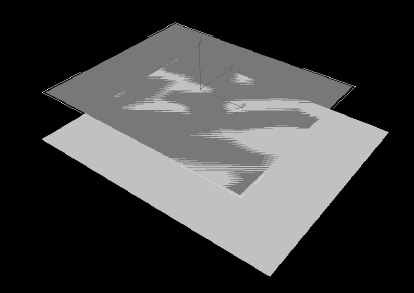
Figure 10–10. Z-fighting in action.
The two rectangles in Figure 10–10 are coplanar; that is, they are embedded in the same plane. Since they overlap, they also share some pixels, which should have the same depth values. However, due to limited floating-point precision, the GPU might not arrive at the same depth values for pixels that overlap. Which pixel passes the depth test is then a sort of lottery. This can usually be resolved by pushing one of the two coplanar objects away from the other object by a small amount. The value of this offset is dependent on a few factors, so it's usually best to experiment. To summarize,
- Do not use values that are too small or large for your near and far clipping plane distances.
- Avoid coplanar objects by offsetting them a little.