
Digital Watermarking Based on Chaotic Map and Reference Register |
|
CONTENTS
5.4 Proposed Watermarking Algorithm
Since multimedia technologies have been becoming increasingly sophisticated in the rapidly growing Internet applications, data security, including copyright protection and data integrity detection, has raised tremendous concerns. One solution to achieve data security is the digital watermarking technology that embeds hidden information or secret data in a host image (Berghel and O’Gorman, 1996; Eggers and Girod, 2002; Wu, 2005). It serves as a suitable tool to identify the source, creator, owner, distributor, or authorized consumer of a document or an image. It can also be used to detect whether a document or an image is illegally distributed or modified.
There are two domain-based watermarking techniques: one in the spatial domain and the other in the frequency domain. In the spatial domain (Voyatzis and Pitas, 1996; Nikolaidis and Pitas, 1998; Wong, 1998; Celik et al., 2002; Mukherjee et al., 2004), we insert watermarks into a host image by changing the gray levels of certain pixels. The embedding capacity may be large, but the hidden information could be easily detected by means of computer analysis. In the frequency domain (Cox et al., 1997; Lin and Chen, 2000; Shih and Wu, 2003, 2005; Wang et al., 2003; Miller et al., 2004; Wu and Shih, 2004, 2006; Zhao et al., 2004), we insert watermarks into frequency coefficients of the image transformed mainly by Discrete Fourier Transform, Discrete Cosine Transform (DCT), or Discrete Wavelet Transform. The hidden information is in general difficult to detect, but we cannot embed a large volume of watermarks in the frequency domain due to significant image distortion.
In general, the frequency-domain watermarking would be robust since the embedded watermarks are spread out all over the spatial extent of an image (Cox et al., 1997). If the watermarks are embedded into locations of large absolute values (we name “significant coefficients”) of the transformed image, the watermarking technique would become more robust. Unfortunately, the transformed images mostly contain only a few significant coefficients, so the watermarking capacity is limited.
Zhao et al. (2004) presented a wavelet-domain watermarking algorithm based on chaotic map. They divided an image into a set of 8 × 8 blocks, and selected the first 256 blocks for embedding watermarks. Miller et al. (2004) proposed a watermarking algorithm using informed coding and embedding. They could embed 1380 bits of data in an image of size 240 × 368; that is, an embedding capacity of 0.015625 bits/ pixel, which still leaves room for improvement.
In this chapter, we propose the strategy of enlarging the watermarking capacity by breaking local spatial similarity in an image to generate more significant coefficients of the transformed image (Wu and Shih, 2007). The rest is organized as follows. We present the block-based chaotic map (BBCM) in Section 5.2. We describe the reference register (RR) in Section 5.3. We explain the proposed watermarking algorithm in Section 5.4. We provide experimental results in Section 5.5. Finally, we draw conclusions in Section 5.6.
In principle, the amount of significant coefficients of a transformed image is limited due to local image similarity. We notice that if the pixel locations are rearranged by destroying the image similarity, the number of significant coefficients in the transformed image would be increased. Figures 5.1a–c show an image, its pixel values, and its transformed image by DCT, respectively. Figures 5.1d–f show the relocated image (i.e., the noisy image), its pixel values, and its transformed image by DCT, respectively. In this example, we define the absolute value > 70 to be significant, and there are totally 14 significant coefficients in Figure 5.1f, but only two significant coefficients in Figure 5.1c. In general, the higher degree of noises an image has, the larger amount of significant coefficients its transformed image possesses. We adopt the chaotic map in this chapter to mess up pixels for obtaining noisy images.
In mathematics and physics, chaos theory deals with the behavior of certain nonlinear dynamic systems that under certain conditions exhibit a phenomenon known as chaos, which is characterized by a sensitivity to initial conditions. The chaotic maps can be considered as a tool to relocate the pixels of an image. Voyatzis and Pitas (1996) presented a well-known chaotic system called “toral automorphism” to a squared image, which first rearranges the locations of an image and then embeds the watermark into the spatial domain of the relocated image. The chaotic map for changing pixel (x, y) to (x′, y′) can be represented by
(5.1) |
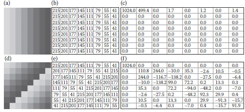
FIGURE 5.1 An example of increasing the number of significant coefficients. (a) and (b) An image and its gray values, (c) the DCT coefficients, (d) and (e) the relocated image and its gray values, (f) the DCT coefficients.
where denotes an integer; N denotes the width of a square image. Let l = 2 and N = 101 in the case of Figure 5.2a of size 101 × 101. When we use Equation 5.1 to rearrange the image, it is obvious that the reconstructed image will be the same as the original image after 17 iterations. Figures 5.2b1–b17 are the iterative noisy images after applying the chaotic map.
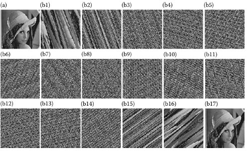
FIGURE 5.2 An example of chaotic map. (a) The original image and (b1–b17) the relocated images in each iteration.
In order to obtain proper coefficients from a transformed image for embedding and extracting watermarks, the concept of RR is developed. Its ability is based on the local image similarity. Therefore, we create the BBCM to partially break the local image similarity in the unit size of block (i.e., a set of connected pixels) instead of pixel. In principle, the bigger the block size is, the larger the local similarity is.
In this section, we present the intersection-based pixels collection (IBPC) method to compute the RR efficiently. The IBPC labels image pixels using two symbols alternatively, and then collects the same symbol to form two subimages. The RR is designed to locate significant DCT coefficients, where watermarks can be embedded. Figures 5.3a–c show three collection approaches in horizontal, vertical, and diagonal directions, respectively. The two subimages are constructed as Figures 5.3d and e. Afterwards, one is used as the RR for indicating significant coefficients, and the other as the container for embedding watermarks.
Note that the pair of subimages generated possess local spatial similarity. From experiments, we observe that the diagonal direction produces better similarity for watermarking. Next, we design a table for nonuniform luminance quantization. It is well known that human perception is more sensitive to low frequencies and less sen-sitive to high frequencies. Let Q Table(i, j) denote the quantization table, where 0 ≤ i, j ≤ 7. After applying scale-up (or scale-down) by quality factor (QF), we obtain the new quantization table NewTable (i, j) as
(5.2) |
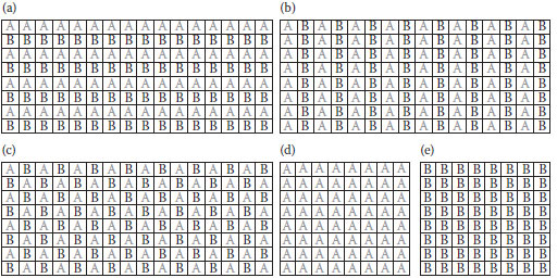
FIGURE 5.3 (a), (b), and (c) respectively show three approaches of collecting the pixels with same label in horizontal, vertical, and diagonal directions, (d) and (e) the generated two subimages.
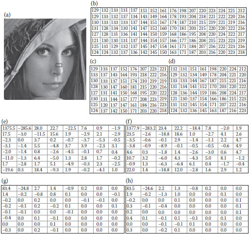
FIGURE 5.4 The similarity of two subimages by IBPC. (a) A Lena imae, (b) the extracted 16 × 8 image, (c) and (d) the pair of extracted 8 × 8 subimages, (e) and (f) the 8 × 8 DCT coefficients, (g) and (h) the quantized images.
Figure 5.4 a shows the Lena image with a 16 × 8 region being cropped as in Figure 5.4b. Figures 5.4c and d show the pair of subimages obtained by the diagonal IBPC. Figures 5.4e and f are their respective DCT images. Figures 5.4g and h show the results after dividing Figures 5.4e and f by the quantization table with QF = 50, respectively. We observe that the two results are very similar.
5.4 PROPOSED WATERMARKING ALGORITHM
The proposed algorithm consists of two procedures: watermark embedding and watermark extracting. During the watermark-embedding procedure, the block-based pixels of an original image are first relocated by BBCM to obtain a noisy image. Second, the noisy image is separated into 16 × 8 subimages. Third, a pair of 8 × 8 containers and an RR are obtained based on IBPC from each 16 × 8 subimage. Fourth, a DCT and a scale-down procedure are applied on the container and RR. Fifth, the proper coefficients are located by the RR, and the watermarks are embedded into the corresponding locations in the container to obtain the frequency-domain watermarked image. After performing the scale-up procedure and an inverse DCT on the 8 × 8 frequency-domain watermarked image, we obtain the 8 × 8 spatial-doma watermarked image and form a new 16 × 8 watermarked image by combining with the original 8 × 8 RR. Then, the watermarked noisy image is obtained by collecting all the 16 × 8 watermarked images. Finally, the watermarked image is obtained by continuously performing the BBCM on the watermarked noisy image. The embeding procedure is described below, and its flowchart is shown in (Fig. 5.5)
The Embedding Procedure:
1. Rearrange a host image H of size n × m to HC by BBCM.
2. Divide a host image HC into a set of subimages, , of size 16 × 8, where 1 ≤ i ≤ ⌊n/16⌋ and 1 ≤ j ≤ ⌊m/8⌋.
3. Build and from each subimages, by diagonal IBPC.
4. Obtain and from and by DCT, respectively.
5. Obtain and from dividing and , by the JPEG quantization table, respectively.
6. Determine the proper positions of significant coefficients in . Let and denote the values of and , respectively. Let denote the result after embedding the message. Let α be a weighting factor and RRTh be the threshold for significant coefficients. If the embedding message is “1” and , we obtain; otherwise, we set . The 8 × 8 are collected to form the cor-responding . In general, a bigger α will produce the higher robustness of watermarking.
7. Obtain from multiplying by the JPEG quantization table.
8. Obtain by applying the Inverse Discrete Cosine Transformation (IDCT) on .
9. Reconstruct by combining and using diagonal IBPC.
10. Obtain the output watermarked image OC by collecting all ’s.
11. Obtain the final watermarked image O by continuously applying BBCM.
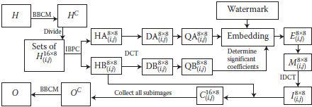
FIGURE 5.5 The embedding procedure.
After receiving the watermarked image O, we extract the watermark information. During the watermark-extracting procedure, the pair of 8 × 8 frequency-domain containers and RR are obtained by using the same procedure as in the embedding procedure. Similarly, the locations for hiding the watermarks are selected by the RR and the watermarks are obtained from the corresponding locations in the container Meanwhile, after removing the watermark from the container, we reconstruct the original 8 × 8 image by the scale-up procedure and the inverse DCT. Finally, the original image is obtained by combining all the 16 × 8 recovered image following the BBCM procedure. The extracting procedure is presented below, and its flowchart is shown in Figure 5.6.
The Extracting Procedure:
1. Rearrange the watermarked image O of size n × m to OC by BBCM.
2. Divide OC into a set of subimages , of size 16 × 8.
3. Build and from each subimage by IBPC.
4. Obtain and from and by DCT, respectively.
5. Obtain and from dividing and by the JPEG quantization table, respectively.
6. Determine the extracting location by checking the significant coefficients of Let and denote the values of and , respectively. Let wdenote the embedded message. If w is set to be 1; otherwise, w is 0.
7. Collect all the subwatermarks to obtain the watermark.
8. Let denote the result after the additional amount is removed. If w is 1, we calculate otherwise, we set The 8 × 8 ’s are collected to form the corresponding
9. Obtain from multiplying by the JPEG quantization table.
10. Obtain by applying the IDCT on .
11. Reconstruct by combining and using diagonal IBPC.
12. Obtain the recovered image RCCby collecting all ’s.
13. Obtain the final recovered image RC by continuously applying BBCM.
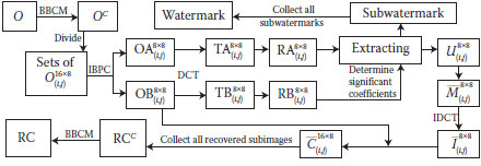
FIGURE 5.6 The extracting procedure.
We conducted experiments using 200 images and provide comparisons with the “iciens” algorithm by Miller et al. (2004). Figure 5.7a shows the relocated image of Figure 5.2a after performing seven iterations of relocation using BBCM, where the block size is 2 × 2 and l = 2. We obtain Figure 5.7b from the small region in (a), and generate (c) and (d) by diagonal IBPC. (Figure 5.7e) and f are, respectively, obtained by DCT followed by a division of the quantization table, where QF = 80. Note that, Figure 5.7e is used as the container for watermark embedding, and (f) is used as the RR as colored in gray. We embed the watermark as “11111111,” so that the original image could be distorted to a large degree. Figure 5.7g provides the result in the frequency domain after embedding watermarks, where α = 0.5 and RRTh = 9. Figure 5.7h shows the watermarked results in the spatial domain.
In the extracting procedure, our goal is to not only correctly obtain the embedded message, but also successfully recover the original image from the watermarked one. An example of the watermarked result of size 16 × 8 is shown in Figure 5.7h. We separate it into two subimages using IBPC as shown in Figure 5.8a and b. Note that, since Figure 5.8b is the same as Figure 5.7d, we generate the same RR. After obtaining Figure 5.8c by DCT, we can extract the watermark as “11111111” and obtain Figure 5.8d. Figure 5.8e shows the recovered result, which is exactly the same as Figure 5.7b.
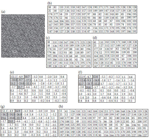
FIGURE 5.7 The embedding strategy. (a) A relocated image, (b) a 16 × 8 subimage, (c) and (d) a pair of extracted results using IBPC, (e) a container, (f) a RR, (g) the result after embedding watermarks, and (h) the watermarked result.
Miller et al. (2004) stated that their watermarking scheme is robust if the message error rate (MER) is lower than 20%. We tested our proposed algorithm under JPEG compression. Figure 5.9a is the original Lena image. After continuously performing nine times of BBCM with block size of 2 × 2, l = 2, α = 0.2, and RRTh = 1, we obtain Figure 5.9b. Figure 5.9c is the watermarked image. Figure 5.9d is the image attacked by JPEG compression using QF = 20. Figure 5.9e is the reconstructed image after the embedded watermarks are removed. The result shows that the proposed watermarking technique obtains MER = 0.19 which is < 20%, and the capacity of 0.116 bits/pixel with PSNR = 35.24 which is much higher than the “iriens” algorithm (Miller et al., 2004) which achieves the capacity of 0.015625 bits/pixel with PSNR = 37.85.
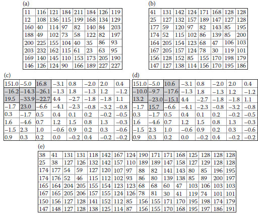
FIGURE 5.8 The extracting strategy. (a) and (b) a pair of extracted 8 × 8 results by IBPC, (c) an 8 × 8 watermarked image by DCT, (d) the result after removing the additional amount, and (e) a reconstructed 16 × 8 image.
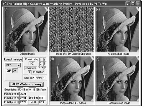
FIGURE 5.9 The robustness experiment using JPEG compression. (a) A 202 × 202 Lena image, (b) the relocated image, (c) the watermarked image, (d) the image attacked by the JPEG compression, and (e) the reconstructed image.
Figure 5.10 and 5.11 show the experiments under low-pass filter and Gaussian noise attacks, respectively. We use the same parameters (block size of 2 × 2, l = 2, α = 0.2, and RRTh = 1) and a 3 × 3 low-pass filter with all ones, and obtain that MER is 16% and the capacity is 0.117 bits/pixel with PSNR = 34.91 in Figure 5.10, and the “iciens” algorithm achieves the capacity of 0.015625 bits/pixel with PSNR = 37.71. We use the same parameters and a Gaussian noise with the standard deviation (SD) 500 and mean 0 to be added into the watermarked image, and obtain MER is 23% and the capacity is 0.124 bits/pixel with PSNR = 34.58 in Figure 5.11, and the “iciens” algorithm achieves the capacity of 0.015625 bits/pixel with PSNR = 37.08.
Although our algorithm achieves a slightly lower PSNR than “iriens” developed by Miller et al. (2004), the watermark capacity derived by our algorithm is much higher than “iriens.” The “iriens” watermarking pursues the robustness by encoding each bit of watermark into several bits using the informed coding and embedding. Our algorithm provides a different perspective of performing the high-capacity watermarking by increasing significant coefficients.
Figure 5.12 shows the effect under JPEG compression with different QFs. For simplicity, we use the symbol “*” to represent our proposed algorithm and “▴” to represent the “iciens” algorithm by Miller et al. (2004). Note that for display convenience, the x-coordinates of JPEG QF are marked in a decreasing order. It is clear that our algorithm produces a slightly higher MER when QF is larger than 40, but a much lower MER when QF is smaller than 40.
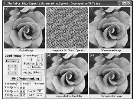
FIGURE 5.10 The robustness experiment using low-pass filter. (a) A 202 × 202 image, (b) the relocated image, (c) the watermarked image, (d) the image attacked by a low-pass filter, and (e) the reconstructed image.
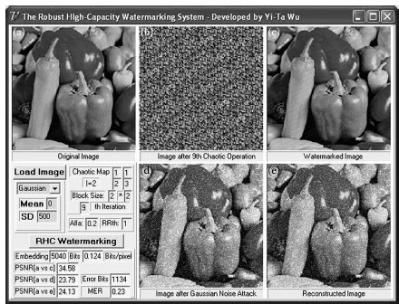
FIGURE 5.11 The robustness experiment using Gaussian noise. (a) A 202 × 202 image, (b) the relocated image, (c) the watermarked image, (d) the image attacked by Gaussian noise, and (e) the reconstructed image.
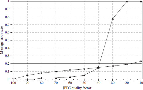
FIGURE 5.12 Robustness versus JPEG compression.
Figure 5.13 shows the case of Gaussian noise with mean 0 and different SDs. The parameters used are block size of 2 × 2, l = 2, α = 0.2, and RRTh = 1. The result shows that our algorithm outperforms iciens in terms of low MER. Moreover, the average watermarking capacity of our algorithm is 0.1238 bits/pixel, which is much higher than 0.015625 bits/pixel in iciens.
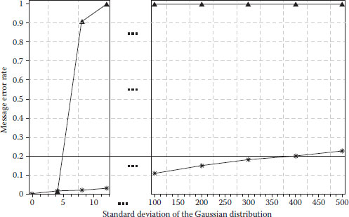
FIGURE 5.13 Robustness versus Gaussian noise.
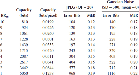
Table 5.1 shows effects of threshold RRTh under JPEG compression with QF = 20 and under Gaussian noise with SD = 500 and mean = 0. We observe that our algorithm can enlarge the capacity (i.e., > 0.12 bits/pixel), as well as maintain a low MER (i.e., < 0.22).
The described new watermarking method is based on the BBCM and the RR. The watermarks are embedded into the DCT coefficients for the robust purpose. In order to increase the watermarking capacity, the noisy image is generated based on the BBCM. The watermark-embedding and extracting procedures are conducted on the DCT coefficients located by the RR. We demonstrate the superiority of the proposed scheme that can enlarge the watermarking capacity as well as maintain a low MER. Experimental results show that the proposed algorithm works accurately under some image-processing distortions, such as the JPEG compression, Gaussian noise, and low-pass filter.
Berghel, H. and O’Gorman, L., Protecting ownership rights through digital watermarking, IEEE Comput. Mag., 29(7), 101–103, 1996.
Celik, M. U., Sharma, G., Saber, E., and Tekalp, A. M., Hierarchical watermarking for secure image authentication with localization, IEEE Trans. Image Process., 11(6), 585–595, 2002.
Cox, I. J., Kilian, J., Leighton, T., and Shamoon, T., Secure spread spectrum watermarking for multimedia, IEEE Trans. Image Process., 6(12), 1673–1687, 1997.
Eggers, J., and Girod, B., Informed Watermarking, Kluwer: Academic, 2002.
Lin, S. D., and Chen, C.-F.m, A robust DCT-based watermarking for copyright protection, IEEE Trans. Consum. Electron., 46(3), 415–421, 2000.
Miller, M. L., Doerr, G. J., and Cox, I. J., Applying informed coding and embedding to design a robust high-capacity watermark, IEEE Trans. Image Process., 13(6), 792–807, 2004.
Mukherjee, D. P., Maitra, S., and Acton, S. T., Spatial domain digital watermarking of multimedia objects for buyer authentication, IEEE Trans. Multimed., 6(1), 1–15, 2004.
Nikolaidis, N., and Pitas, I., Robust image watermarking in the spatial domain, Signal Process., 66(3), 385–403, 1998.
Shih, F. Y., and Wu, Y. T., Combinational image watermarking in the spatial and frequency domains, Pattern Recognit., 36(4), 969–975, 2003.
Shih, F. Y., and Wu, Y., Enhancement of image watermark retrieval based on genetic algorithm, J. Vis. Commun. Image Represent., 16, 115–133, 2005.
Voyatzis, G., and Pitas, I., Applications of toral automorphisms in image watermarking, in Proceedings of the IEEE International Conference on Image Processing, Vol. 2, Lausanne, Switzerland, pp.237–240, September 1996.
Wang, H., Chen, H., and Ke, D., Watermark hiding technique based on chaotic map, in Proceedings of the IEEE International Conference on Neural Networks and Signal Processing, Nanjing, China, pp.1505–1508, December 2003.
Wong, P. W., A public key watermark for image verification and authentication, in Proceedings of the IEEE International Conference Image Processing, Chicago, IL, pp. 425–429, 1998.
Wu, Y. T., Multimedia Security, Morphological Processing, and Applications, PhD dissertation, New Jersey Institute Technology, Newark, 2005.
Wu, Y. T., and Shih, F. Y., An adjusted-purpose digital watermarking technique, Pattern Recognit., 37(12), 2349–2359, 2004.
Wu, Y. T., and Shih, F. Y., Genetic algorithm based methodology for breaking the steganalytic systems, IEEE Trans. Syst. Man Cybern. B, 36(1), 24–31, 2006.
Wu, Y., and Shih, F. Y., Digital watermarking based on chaotic map and reference register, Pattern Recognit., 40(12), 3753–3763, 2007.
Zhao, D., Chen, G., and Liu, W., A chaos-based robust wavelet-domain watermarking algorithm, Chaos Solitons Fractals, 22, 47–54, 2004.