
An Efficient Block-Based Fragile Watermarking System for Tamper Localization and Recovery |
|
CONTENTS
10.2.1 Vector Quantization Attack
10.2.2 Cyclic Redundancy Checksum
10.2.3 Comparison of Existing Methodologies
10.2.4 Lookup Table Generation
10.3.3 Recovery OF Tampered Blocks
10.3.4 Extension to Color Images
Digital information and data are transformed more often over the Internet now than ever before. Creative approaches to storing, accessing, and distributing data have generated many benefits for the digital multimedia field, mainly because of properties such as distortion-free transmission, compact storage, and easy editing. But due to the availability of multimedia manipulation software in the market, a malicious attacker can easily modify the image content. Therefore, the authentication and recovery of the multimedia content has been becoming increasingly important in recent years. Digital watermarking (Cox et al., 2001; Shih, 2007) is the leading technique for tamper localization and recovery of the modified content.
Digital watermarking (Cox et al., 2001; Shih, 2007) can be categorized into three types based on its purposes. The first type is robust watermarking, which provides the content protection of multimedia content by resisting the watermark against signal-processing operations. The second type is fragile watermarking, which authenticates the multimedia content. The watermark becomes invalid even if a single bit is modified in the content. The third type is semi-fragile watermarking, which acts in between robust and fragile watermarking. It resists the watermark against legitimate attacks and becomes invalid against malicious attacks. Although fragile (Lin et al., 2004, 2005; Lee and Lin, 2008) and semi-fragile (Fridrich, 1998; Kundur and Hatzinakos, 1999) techniques provide image authentication, the fragile watermarking technique has the advantage of tamper localization with recovery of the modified content.
The fragile watermarking uses two ways to authenticate an image—blockwise independent and blockwise dependent. Blockwise-independent (Celik et al., 2002) techniques use image ids, block indices, and hierarchical signatures to authenticate images and resist the vector quantization (VQ) (Holliman and Memon, 2000) attack. They need more authentication information to store in order to counteract the VQ attack. Blockwise-dependent techniques (Tanebaum, 2003; Lin et al., 2004, 2005; Lee and Lin, 2008), on the other hand, map the blocks using a secret key. The mapping is one-to-one. The feature of each block together with the authentication information of the corresponding mapping block is embedded into the mapping block. Each block is authenticated based on the information stored in that block together with the feature stored in the corresponding mapping block. It has the advantage of recovering the tampered block information from the feature stored in the corresponding mapping block along with the localization of tampered area. In this chapter, we focus on blockwise-dependent fragile watermarking for the purpose of image authentication and recovery.
Lin et al. (2004) designed a fragile watermarking scheme for image authentication with localization and recovery with a block size of 8 × 8. The scheme suffers from poor localization accuracy; that is, if a single pixel is modified, the whole 8 × 8 block is detected as tampered and poor recovery rate although it counteracts the VQ attack. Lin et al. (2005) came up with a different technique with a block size of 4 × 4, that is, better localization accuracy, but it still suffers from lack of recovery information if the corresponding mapping block is also marked as tampered. Wang and Tsai (2008) proposed a technique based on fractal code embedding and image inpainting. Their technique embeds the recovery information of blocks of ROI (region of interest) into the blocks other than ROI. This method also suffers from the lack of recovery information. Wang and Chen (2007) proposed a tamper detection and recovery scheme for color images based on a majority voting scheme with a block size of 2 × 2. The method still suffers from the lack of recovery information.
Recently, Lee and Lin (2008) proposed a dual-watermarking scheme for tamper detection and recovery with a block size of 2 × 2, which embeds the recovery information in two blocks instead of one block. Although it achieves impressive tamper localization and recovery information, it suffers from two main drawbacks. The first drawback is that it fails to detect the bit changes in the five most significant bits (MSBs) of each pixel. The second drawback is the lack of support against the VQ attack. Because each block is authenticated individually, that is, considering only the information stored in that block, we can substitute different watermarked image blocks from vector quantization code book to form an authenticated image. This method also uses parity bit checksum (Tanebaum, 2003) for authentication. The disadvantage of parity sum is that it only detects even number of changes. This drawback is discussed in experimental results. In this chapter, we propose a watermarking system that not only thwarts the VQ attack, but also has good tamper localization accuracy and recovery rate (Edupuganti et al., 2011).
The rest of the chapter is organized as follows. Section 10.2 presents the related work to our method. Our proposed method is presented in Section 10.3. Experimental results and discussions are presented in Section 10.4. Finally, conclusions are drawn in Section 10.5.
10.2.1 VECTOR QUANTIZATION ATTACK
Holliman and Memon (2000) presented a counterfeiting attack on blockwise-independent watermarking schemes. In such a scheme, the attacker generates a forgery image by the collage of authenticated blocks from different watermarked images. Because of the blockwise nature of embedding and authentication processes, the forgery image is authenticated as valid. Additionally, if the database of watermarked images is huge, the attacker can easily generate a collage image that is identical to the unwatermarked image.
10.2.2 CYCLIC REDUNDANCY CHECKSUM
In the computation of cyclic redundancy checksum (CRC) (Tanebaum, 2003; Lin et al., 2004), a k-bit string is represented by the coefficients of a k-1-degree polynomial, that is, coefficients of x0 to xk–1. The MSB of the k-bit string becomes the coefficient of xk–1, second MSB becomes the coefficient of xk–2, and continuously the least-significant bit (LSB) becomes the coefficient of x0. For example, the polynomial representation of the bit string 1011 is x3 + x + 1. To compute the CRC-r authentication information of a bit string, we pad “r” zeros to the end of the bit string. Then we divide the resulting bit string with an “r” degree polynomial. Then, we subtract the remainder from the bit string padded with zeros. The resultant bit string after subtraction is the authentication information. The subtraction is done in modulo-2 arithmetic. To check if a CRC-r-generated bit string is modified or not, we divide the bit string with the r-degree polynomial used in the generation stage. If there is a remainder after division, it means that the bit string is modified; otherwise, the bit string is not manipulated.
10.2.3 COMPARISON OF EXISTING METHODOLOGIES
In Table 10.1, a comparison of three existing blockwise-dependent fragile watermarking schemes is made using different characteristics. The three schemes considered are Lin et al. (2004, 2005) and Lee and Lin (2008). Our proposed algorithm is designed to achieve the best characteristics of these three schemes, that is, tamper localization size of 2 × 2, two copies of recovery information, support against the VQ attack, and detection of the modification in higher-order bits. Our proposed scheme can be applied to grayscale and color images. In the proposed algorithm, the probability to thwart the VQ attack and higher-order bit modification is higher than that of Lin et al. (2004, 2005) because of the two copies of recovery information. In order to achieve the dual recovery, we adopt the generation of lookup table, which is similar to Lee and Lin (2008).
TABLE 10.1
Comparison of Three Existing Schemes
Characteristic |
Lin et al. (2004) |
Lin et al. (2005) |
Lee and Lin (2008) |
Minimum block size of tamper localization |
8×8 |
4×4 |
2×2 |
Copies of recovery information |
1 |
1 |
2 |
Detection of VQ attack |
Yes |
Yes |
No |
Number of bits modified in each pixel of the original image |
2 (LSB) |
2 (LSB) |
3 (LSB) |
Blockwise dependent detection |
Yes |
Yes |
No |
Detection of changes in the higher order bits of each pixel |
Yes, if the corresponding mapping block is valid |
Yes, if the corresponding mapping block is valid |
No |
Authentication method used |
MD5 with CRC |
Parity bit |
Parity bit |
10.2.4 LOOKUP TABLE GENERATION
We outline the procedure of the lookup table generation as follows:
1. Let A be a host image of size M × M, where M is a multiple of 2.
2. Divide the image A into blocks of size 2 ×2. Calculate the block number for each block as
(10.1) |
where
3. Calculate the block number for each block as
(10.2) |
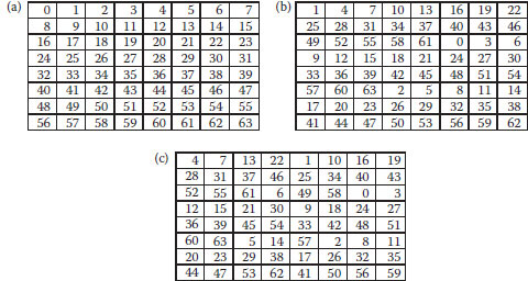
FIGURE 10.1 (a) Original table, (b) the mapping table obtained by Equation 10.2, and (c) the lookup table after column transformation.
where i, j ∈[1, M/2×M/2]; X, X’ ∈ [0, N-1] are the corresponding one-to- one mapping block numbers, k ∈ [2, N-1] (secret key) is a prime number, and N = M/2 × M/2 is the total number of blocks in the image. Note that if k is not a prime number, we will not achieve one-to-one mapping.
4. Shift the columns in X’, so the blocks that belong to the left half of the image are moved to the right half and the blocks that belong to the right half of the image are moved to the left half. Denote the new lookup table as X″. Figure 10.1 shows the generation of a lookup table for a 16 × 16 image with k = 3.
The design of our proposed scheme is divided into three modules as watermark embedding, tamper detection with localization, and recovery of tampered blocks.
The watermark-embedding process consists of the following six steps:
1. Let A be a host image of size M × M, where M is a multiple of 2. Compute the block numbers (X) and lookup table (X″) as described in Section 10.2.4.
2. Divide the host image A horizontally into two halves as shown in Figure 10.2. The corresponding blocks in the two halves form a partner-block, that is, blocks 0 and 32, 1 and 33, 16 and 48, and so on.
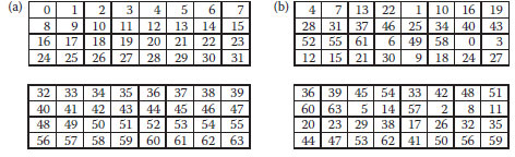
FIGURE 10.2 (a) Two-halves of a 16 × 16 image with block numbers and (b) two-halves of the corresponding lookup table generated with k=3.
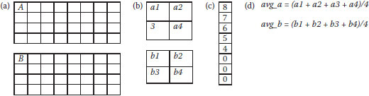
FIGURE 10.3 (a) The partner block a, b of image A, (b) 2 × 2 view of a, b, (c) replacing three LSBs of each pixel with zero, and (d) computation of the average intensity.
3. For each partner-block a, b in the host image A, we set the three LSBs of each pixel in the blocks a and b to zero. Compute the average intensities avg_a and avg_b as shown in Figure 10.3.
4. Determine x, y corresponding mapping partner block of the partner block a, b from the look up table X". The 10-bit feature of partner block a, b is shown in Figure 10.4. Pad two zeros to the end of the feature computed. We use the CRC (Tanebaum, 2003; Lin et al., 2004) to compute authentication information. Obtain the CRC-2 by dividing the 12-bit feature with a secret polynomial of degree 2 and subtracting the remainder from the feature.
5. The 12-bit watermark of the partner block a, b is shown in (Figure 10.5b). Embed the computed 12-bit watermark into the three LSBs of each pixel of the corresponding mapping partner block x, y as shown in (Figure 10.5c). Note that the same watermark is embedded into two blocks, that is, x and y.
6. After completing the embedding process for each partner block in the host image A, we will obtain the watermarked image B.
The tamper detection is done in four levels. In each level, we try to reduce the false alarms along with the localization of the tampered area. We denote the image under detection as B′
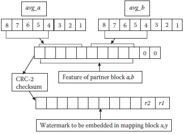
FIGURE 10.4 Feature of partner block a, b.
1. The image under the detection process is divided into blocks of size 2 × 2, and the mapping sequence is generated as explained in Section 10.2.4.
2. Level-1 detection: For each block b, the 12-bit watermark is extracted from the three LSBs of each pixel. Divide the extracted watermark with the secret polynomial used in the embedding stage. If there is a remainder, it means that the block is tampered in the least significant three bits and mark b as invalid; otherwise, mark b as valid. Level-2 and Level-3 are used to reduce the false alarms.
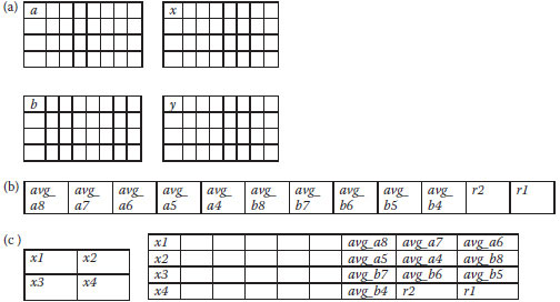
FIGURE 10.5 (a) Partner block a, b and its mapping partner block x, y, (b) 12-bit watermark, and (c) embedding sequence of 12-bit watermark in each block of the mapping partner-block.
3. Level-2 Detection: For each valid block b after level-1 detection, we conduct the following:
If b is a block in the border of the image, then
If number of invalid blocks in 3 × 3 neighborhood of b ≥ 3, mark b as invalid;
Else
If number of invalid blocks in 3 × 3 neighborhood of b ≥ 5, mark b as invalid;
4. Level-3 detection: For each valid block b after level-2 detection, we conduct the following:
If b is a block in the border of the image, then
If number of invalid blocks in 5 × 5 neighborhood of b ≥ 8, mark b as invalid;
Else
If number of invalid blocks in 5 × 5 neighborhood of b ≥ 13, mark b as invalid;
In general, if a block is tampered, then there are more chances that the neighboring blocks are also tampered. Thus, Level-2 and Level-3 reduce the false acceptance ratio of invalid blocks and help to reduce the false alarms.
5. Level-4 detection: This level is to detect any changes in the five MSBs of each pixel of the valid blocks and to thwart the VQ attack. In this level, we mark the block invalid only if there is a mismatch of the feature with both of the mapping blocks, so the false alarms can be reduced. For each valid block b after Level-3 detection, we set the three LSBs of each pixel in block b to zero. Compute the average intensity of block b, which is denoted as avg_b. Determine the corresponding mapping partner block x, y from the lookup table, and perform the following task:
If x is valid, then
extract the 12-bit watermark from x;
If b ∈{upper half of the image}, then
compare 5 MSBs of avg_b against bits 1 to 5 of the extracted watermark;
Else
compare 5 MSBs of avg_b against bits 6 to 10 of the extracted watermark;
If there is any mismatch in bit comparison, then mark b as invalid;
If b is invalid, then
If y is valid, then
extract the 12-bit watermark from y;
If b ∈{upper half of the image}, then
compare 5 MSBs of avg_b against bits 1 to 5 of
the extracted watermark;
Else
compare 5 MSBs of avg_b against bits 6 to 10 of the extracted watermark;
If there is any mismatch in bit comparison, then mark b as invalid;
Else mark b as valid;
Else if y is valid, then
extract the 12 - bit watermark from y;
If b ∈{upper half of the image}, then
compare 5 MSBs of avg_b against bits 1 to 5 of the extracted watermark;
Else
compare 5 MSBs of avg_b against bits 6 to 10 of the extracted watermark;
If there is any mismatch in bit comparison, then mark b as invalid;
10.3.3 RECOVERY OF TAMPERED BLOCKS
As in Lee and Lin (2008), the recovery of tampered blocks is done in two stages. Stage-1 is responsible for recovery from the valid mapping blocks, which is the recovery from the embedded watermark. In stage-2, we recover the image by averaging the 3 × 3 neighborhood.
1. For each invalid block b, find the mapping block x from the lookup table.
2. If x is valid, then x is the candidate block and go to step 5.
3. Determine the partner block of x and denote it as y.
4. If y is valid, then y is the candidate block; otherwise, stop and leave b as invalid.
5. Retrieve the 12-bit watermark mark from the candidate block.
6. If block b is in the upper half of the image, then the 5-bit representative information of block b starts from the first bit; otherwise, it starts from the sixth bit.
7. Pad three zeros to the end of 5-bit representative information.
8. Replace each pixel in block b with this new 8-bit intensity and mark b as valid.
For each invalid block b, we recover the block by averaging the surrounding pixels of block b in the 3 × 3 neighborhood as shown in Figure 10.6.
10.3.4 EXTENSION TO COLOR IMAGES
To extend the proposed scheme to color images, we consider red, green, and blue components of the color image. The embedding process is done in each of the three components individually, and then each component is assembled to obtain a watermarked image as shown in Figure 10.7a. Like embedding process, the detection is also done on individual components. Then each block in the three components is validated, such that if the block is invalid in any of the red, green, and blue components, then mark the block invalid in all the three components. Finally, each component is assembled back to obtain the watermarked image as shown in Figure 10.7b The recovery process is conducted in each of the components individually as described in Section 10.3.3 by considering the localization image in Figure 10.7b. Finally, combining the red, green, and blue components gives the recovered color image.
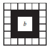
FIGURE 10.6 The 3 × 3 neighborhood of block b.
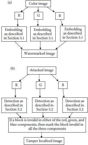
FIGURE 10.7 (a) Embedding process for color images and (b) tamper detection process for color images.
In this section, we use two different measures: one is peak signal-to-noise ratio (PSNR) to measure the quality of the watermarked image, and the other is percentage of recovery (PR) to compare the recovery rate of our technique with the existing techniques. The PSNR of an image A with respect to an image B is defined by
(10.3) |
where MAXI is the maximum gray value of the images A and B, and MSE is the mean square error defined by
(10.4) |
where m × n is the size of the images A and B. The more the PSNR ratio, the less is the distortion, that is, the more is the image quality. The PR of an image I is defined by
(10.5) |
where SIZEM(I) is the size of the modified portion in the image I, and SIZER(I) is the size of recovered portion of the modified portion after stage-1 recovery, that is, recovery from features stored in mapping block. The more the PR, the more is the recovery and vice versa. Experiments are conducted on grayscale images of size 256 × 256 with k = 13 and 101 as the secret polynomial.Table 10.2 lists the PSNR values of different watermarked images by applying the proposed method.
TABLE 10.2
PSNR Values of Different Watermarked Images by the Proposed Method
![]()
We conduct various types of cropping attacks in the experiments. There are 12 distinct cropping patterns used as shown in Figure 10.8. Table 10.3 lists the resulting PR values of applying Lin et al. (2004), Lin et al. (2005), and the proposed schemes under these 12-pattern cropping attacks. We observe that the proposed algorithm outperforms the other two algorithms.
We also measure the performance of the proposed technique in terms of PR by considering different percentages of cropping. The cropping is carried out from the top-left corner of the image. The graph in Figure 10.9 gives the performance of the proposed scheme against Lin et al. (2004), Lin et al. (2005). It is observed that the proposed scheme produces a much higher number of recovery pixels than the other two schemes. Figure 10.10 shows the application of our technique on a color image, where the image of the license plate number of the car was removed and can still be recovered. Figure 10.11 demonstrates that the use of random shape cropping cannot affect the accurate recovery of the Barbara image.
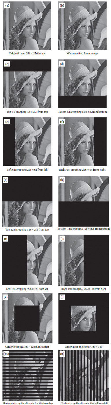
FIGURE 10.8 Different cropping styles.
TABLE 10.3
Comparisons of the PR Values under the 12-Pattern Cropping Attacks
Cropping style |
Lin et al. (2004) PR |
Lin et al. (2005) PR |
Proposed PR |
Top -64 |
75.00 |
69.34 |
100.00 |
Bottom-64 |
75.00 |
69.34 |
100.00 |
Left-64 |
75.00 |
62.50 |
100.00 |
Right-64 |
75.00 |
62.50 |
100.00 |
Top-128 |
50.00 |
46.24 |
100.00 |
Bottom-128 |
50.00 |
46.24 |
100.00 |
Left-128 |
50.00 |
40.63 |
100.00 |
Right-128 |
50.00 |
40.63 |
100.00 |
Outer-64 |
27.86 |
23.57 |
50.80 |
Center-64 |
83.59 |
90.33 |
100.00 |
Horizontal-8 |
50.00 |
46.09 |
45.90 |
Vertical-8 |
50.00 |
50.00 |
48.44 |
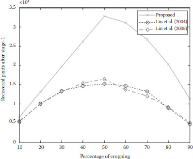
FIGURE 10.9 Comparisons of the proposed scheme with different percentages of cropping.
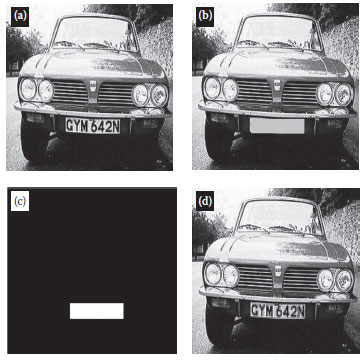
FIGURE 10.10 (a) A watermarked image containing a car, (b) a modified image with the license plate number removed, (c) the result of tamper detection, and (d) the result of the recovered image.
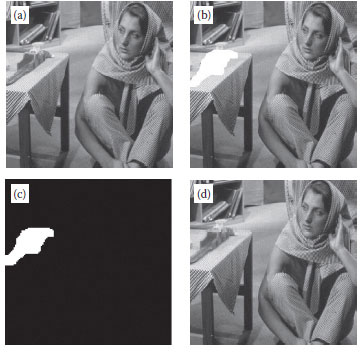
FIGURE 10.11 (a) A watermarked Barbara image, (b) a modified image with random shape cropping, (c) the result of the tamper localization image, and (d) the result of the recovered image.
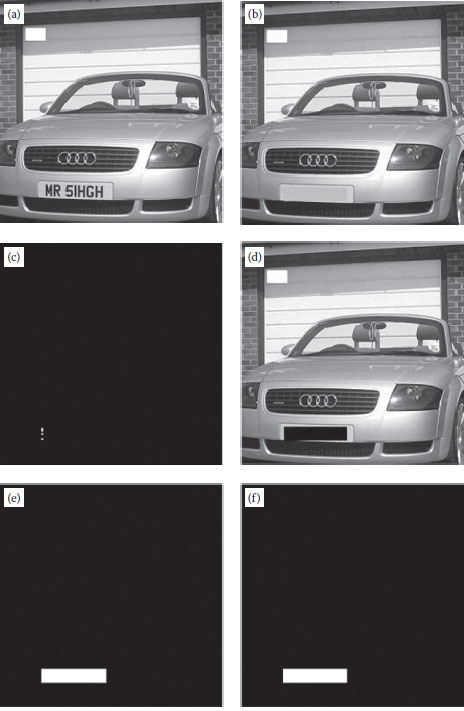
FIGURE 10.12 (a) An original image, (b) the modification of license plate by gray value 193, (c) the detection of (b) by Lee and Lin (2008), (d) the modification of license plate by black value 0, (e) the detection of (d) by Lee and Lin (2008), and (f) the detection of (b) and (d) by our proposed scheme.
Lee and Lin (2008) used the parity sum for authenticating the individual blocks. This approach has a problem of detecting only even number of changes in the bit string. In their authentication method, the fist authentication bit is the XOR of first 10 bits of the feature, and the second authentication bit is the opposite of first authentication bit. Therefore, if each pixel is modified with a gray value whose two LSBs are opposite to each other, then it is less likely for their method to detect the modification. Figure 10.12 shows the results of the modification and its corresponding localization with a different gray value other than black. Their method detects the modification in the case of black pixel replacement, but fails to detect the modification by replacing some other gray values. In Figure 10.12(f), we show that the proposed method can detect both black pixel and other gray value modifications.
The described new efficient fragile watermarking technique is proposed for authentication and recovery. Our method is designed to meet the desired characteristics of a fragile watermarking system for tamper localization and recovery. The characteristics include tamper localization size of 2 × 2, support against the VQ attack, dual recovery, and reduced false alarms. We apply the CRC-2 checksum for authentication of the feature stored in each block. The proposed method can be applied to both grayscale and color images. Experimental results show that our method has better recovery rate than Lin et al. (2004), Lin et al. (2005) and has the advantages of support against the VQ attack, changes in higher-order bits, and the detection of modification with any gray value over Lee and Lin (2008).
Celik, M. U., Sharma, G., Saber, E. and Tekalp, A. M., Hierarchical watermarking for secure image authentication with localization, IEEE Trans Image Process, 11(6), 585–594, 2002.
Cox, I. J. Bloom, J., Miller, M., and Cox, I., Digital Watermarking Principles & Practice, Morgan Kaufmann, San Francisco 2001.
Edupuganti, V. G., Shih, F. Y., and Chang, I., An efficient block-based fragile watermarking system for tamper localization and recovery, Autosoft J Intell Autom Soft Comput, 17(2), 257–267, 2011.
Fridrich, J., Image watermarking for tamper detection, Proc IEEE Intl Conf Image Process, Chicago, II, vol.2, pp. 404–408, Oct 1998.
Holliman, M., and Memon, N., Counterfeiting attacks on oblivious blockwise independent invisible watermarking schemes, IEEE Trans Image Process, 9(3) 432–441, Oct 2000.
Kundur, D., and Hatzinakos, D., Digital watermarking for telltale tamper proofing and authentication Proc IEEE, 87(7) 1167–1180, 1999.
Lee, T. Y., and Lin, S.D. , Dual watermark for image tamper detection and recovery, Pattern Recognit, 41(11) 3497–3506, 2008.
Lin, P.I., Hsieh, C.K., and Huang, P.W., A hierarchical digital watermarking method for image tamper detection and recovery, Pattern Recognit, 38(12) 2519–2529, 2005.
Lin, P.I., Huang, P. W., and Peng, A. W., A fragile watermarking scheme for image authentication with localization and recovery, Proc IEEE Sixth Intl Symp Multimedia Software Eng, Miami, FL, pp. 146–153, 2004.
Shih, F. Y., Digital Watermarking and Steganography: Fundamentals and Techniques, CRC Publisher, Boca Raton, FL, 2007.
Tanebaum, A. S., Computer Networks, Fourth Edition, The Netherlands Pearson Education International, Upper Saddle River, New Jersey, 2003.
Wang, M. S., and Chen, W. C., A majority voting based watermarking scheme for color image tamper detection and recovery, Comput Stand Interfaces, 29(5) 561–570, 2007.
Wang, S. S., and Tsai, S. L., Automatic image authentication and recovery using fractal code embedding and image painting, Pattern Recognit, 41(2) 701–712, 2008.