Now that you have an understanding of the fundamental concepts, tools, and workflow for 3D composition in Fusion, we should look at a specific application of this called 3D titling, which VFX agencies are often approached to do for clients. Thanks to the text 3D tool, which we haven’t yet taken a look at, but should, these projects can be done 100 percent within a Fusion 2D and 3D composition environment.
We will look at how to create cinema-quality 3D text and how to apply advanced effects to your 3D titling pipeline.
3D Text Tool: Create Professional 3D Text
Fusion has always had 3D text capability to provide a titling engine to VFX developers, as film credits and television shows have always required either 2D or 3D text production. The text engines (2D text and 3D text) are very similar in Fusion, but since we are in the 3D section of the book, we’ll look at the more advanced text 3D node tool in Fusion, and how to utilize it to create professional 3D text and text titling visual effects.
Classic 3D Text Extrusion: Basic 3D Text Modeling
Let’s jump right in and fire up Fusion and create a new project. Right-click in the flow node editor and use the Add Tool ➤ 3D ➤ Text 3D menu sequence to add a text 3D node , as shown in Figure 16-1. Enter “VFX Fundamentals” into the Styled Textbox in the control panel area. I used an Arial font and default 1.0 Size setting. Click the view dot at the bottom of the tool and resize that viewport to fill the screen, as the aspect ratio is very wide for this text element. All of this can be seen in Figure 16-1, as well as in the Extrusionsection of the Text3D1 node control panel, currently in its collapsed (closed) state.
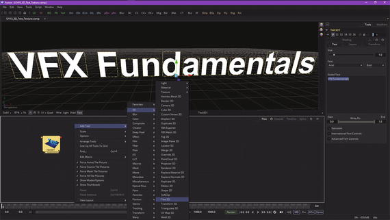
Figure 16-1. Add a text 3D node, enter “VFX Fundamentals” text
Now we can add the merge 3D node to create the 3D scene, and then wire the text 3D node into that. Then we can add the camera 3D node and wire that to the merge 3D node before adding a renderer 3D node and wiring it to the merge 3D node. Select View1 for the renderer 3D node and View2 for the merge 3D node, as seen in Figure 16-2.
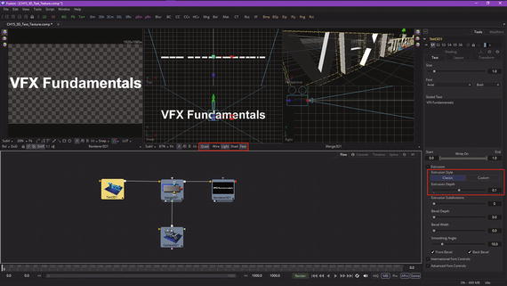
Figure 16-2. Create 3D scene and configure views to show output
As you can see in Figure 16-2, I have selected Classicor basic (simple) 3D text extrusion and used an initial 0.0125 value to extrude the text. I’ve opted to bevel both the front and the back, as you can see in Figure 16-3, since this is 3D text, and it may be seen from more than one angle. I am going to select both the “Quad” and “Light” options in the merge View2, so you can see the default scene lighting, as well as the camera positioning and the smooth, professional results that Fusion 8 should give you for your 3D text titling VFX project workflows.
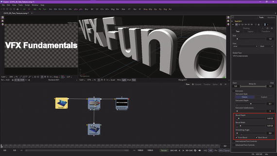
Figure 16-3. Set extrusion and beveling parameters
Next, let’s add a spot light, so that we can cast shadows in this 3D text titling project. Use Add Tool ➤ 3D ➤ Spot Lightfrom the flow node editor context menu, and wire the spot light up to the merge 3D scene, as is shown in Figure 16-4.
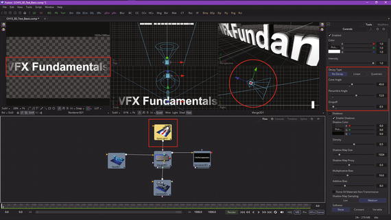
Figure 16-4. Add a spot light, and set its two cones and falloff
I initially used No Decayfor a bright spot light effect and set Cone Angleto 45°, Penumbra Angleto 12°, and Falloffto 0.5 or 50 percent, as shown highlighted in red on the right side of Figure 16-4. The results of these settings can be seen in the renderer 3D View1, on the left side, as well as in the merge 3D View2 quad viewports, seen on the right in Figure 16-4.
To enable these lighting effects to show in the Front or in the Perspective quad viewports, or in both, you must click your mouse in each viewport and then select the “Light” option at the bottom of the Quad view.
These are the minimum settings that you would need in order to implement basic 3D text titling assets in Fusion 8. I will show you some more advanced ways to enhance the visual effect of the 3D text title over the rest of this chapter.
To see that this is indeed 3D mesh geometry , click the Wire button on the bottom of your merge 3D View2, and also turn off the Fast shader (for better wire quality), shadows (Shad), and the Quad view, so you are showing only the Perspective view . This is shown in Figure 16-5, highlighted in red at the bottom of the View2.
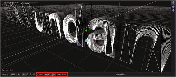
Figure 16-5. Turn on “Wire” and “Light” options to see the text’s wireframe
You can see the beveling in the back of the 3D text with this current Perspective view; to see it better, turn off the “Light” option for the View2, as shown in Figure 16-6, which will now show every edge.
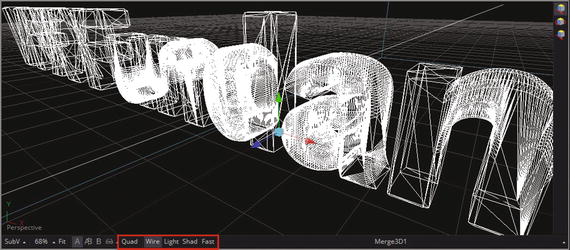
Figure 16-6. Turn off “Light” option to see beveling in the back of the text
Next, set the Extrusion Subdivisionslider to 3 to make the mesh more complex, as seen in Figure 16-7. If you are going to deform(bend, twist, etc.) the mesh and need more data points, you will get a better (smooth) deformation result with more complex mesh. There should be another slider for adding subdivisions in the other dimension (between text shape vertices); hopefully, Blackmagic Design will add this in the future. The reason that Fusion’s 3D text tool is not as seamless or advanced as other features is that it was acquired by Eyeon for the software, and was not coded from scratch. This may have to be done eventually in order to make this area of the software as professional as the rest of Fusion 8, and more seamless with other nodes (tools).
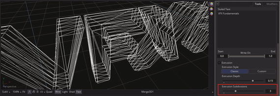
Figure 16-7. Set Extrusion Subdivision to 3, creating four sections
Next, let’s take a look at how to create more advanced 3D text objects by using the custom 3D text option. This allows a spline-based approach to defining an extrusion profile.
Custom 3D Text Extrusion: Complex 3D Text Model
To give us more flexibility in modeling and animation, and to change this wide aspect ratio for your logo, let’s make VFX and Fundamentals two separate nodes. Edit the Text3D1 node to be just Fundamentals, as shown in Figure 16-8, and also edit your spot light parameters so as to fit the shorter 3D text span, as shown circled in red at the right in Figure 16-8.
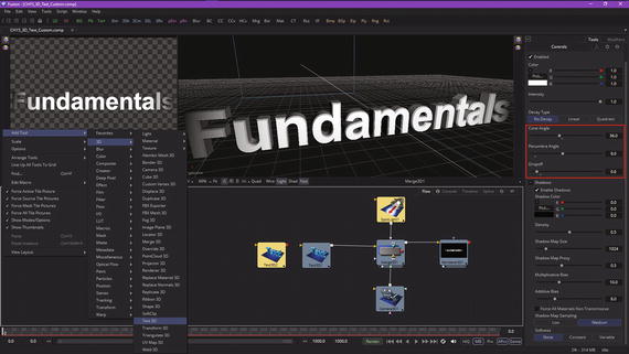
Figure 16-8. Make Text3D1 Fundamentals, and add a Text3D2 node
I set Cone Angle to 36°, Penumbra Angle to 9°, and Falloff of 0.6 to achieve the dramatic lighting effect for this bottom Fundamentals portion of the logo. I’ll use Text3D2 to add a larger VFX portion to the logo that will be centered directly above the much longer Fundamentals lower component.
To do this, use an Add Tool ➤ 3D ➤ Text 3D context menu to add a Text3D2 node, also seen in Figure 16-8. I combined two screenshots into one (there are a lot of figures in this chapter), in case you are wondering why both Camera and Text3D are selected.
Wire the Text3D2 into your merge 3D scene node, as shown in Figure 16-9, and set the text value to “VFX” and the size to be twice as large as Fundamentals, or a value of 2.0.
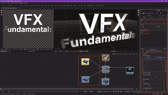
Figure 16-9. Rename text 3D nodes; set VFX text basic parameters
Open the Extrusion section of the Text3D2 control panel, and set Extrusion Depthto be twice the Text3D1 extrusion depth, or a data value of 0.3. Fusion sets default Subdivision and Smoothing Angledata values to 40 and 10.0, respectively.
Also notice in Figure 16-9 that I’ve renamed the Text3D1 node to be Fundamentals and the Text3D2 node to be VFX_Text3D.
Also shown in Figure 16-9 is your Custom Extrusion Stylebutton. This allows you to spline model a 3D text profile. Once you select this, you’ll see a starting spline profile setting in the extrusion profile graph. To see a detailed version of this spline, select the Spline tab , as shown in red in Figure 16-10.
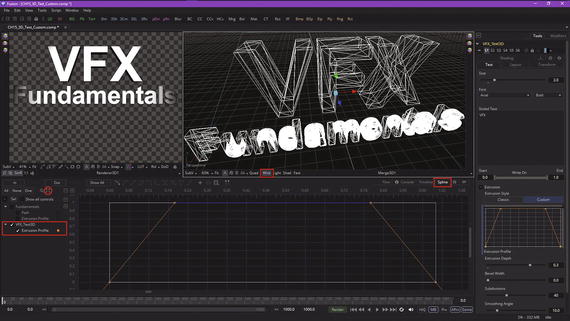
Figure 16-10. Use a spline editor to edit the extrusion profile
When you first open the Spline tab, you’ll see a vertical line, a compressed version, which you can expand using the Zoom View icon, seen circled in red on the left in Figure 16-10. I also set the merge 3D scene view to Wire mode, so that you can see that Fusion puts polygons (edges and faces) in place where the points in the spline are located. If you use curves, Fusion will add points accordingly to approximate this new curvature.
Let’s dive right in and see how it works! Click once in the center of the top straight section of the extrusion spline and pull down to create a “V.” Set the VFX_Text3D node view dot to View1 and position your 3D view as seen in Figure 16-11 so that you can see what is going on with your actual 3D model. If you do not see a result, then set Bevel Widthto 0.05. The custom 3D text modeler seems to need a bevel to be set in order to do its thing! Add a second point to the straight top spline, creating a flat-bottom ditch, as seen in red on the right of Figure 16-11.
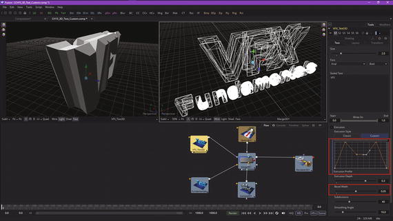
Figure 16-11. Set Bevel Width to 0.05, and create a flat-bottom ditch
As you can see in View1 (text 3D node preview), the spline is now defining the extrusion of the VFX part of the logo. Now, click the Spline tab; we will use the grid and do some more detailed extrusion spline modeling to create some really great 3D text modeling effects .
Add points on either side of the ditch and pull the flat part up and in, and the new points down, to create a “W” shape, as is seen in Figure 16-12. As you can see in the preview, this gives you a professional extrusion effect. Notice Fusion 8 only adds points and edges as needed to create this 3D text object.
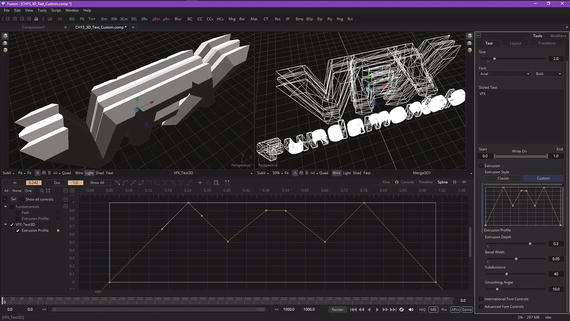
Figure 16-12. Create a “W” straight-edged shape in the spline editor
Add two more points to make a notch in the middle of the spline, as is shown in Figure 16-13. Keep all sections straight by moving only the points at this point (no pun intended), and not moving the tensioning handle (at least not yet). I used the spline editor grid intersections so that you can copy my work.
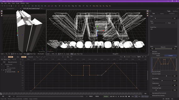
Figure 16-13. Create a notch in the center of the extrusion profile
Select the two corner points away from the notch, to pull out your tension handles . This will create a nice curve for the bottom of the trough, as can be seen in View1 in Figure 16-14.
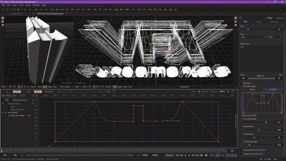
Figure 16-14. Create a smooth trough bottom using the tension handles
Smooth the transition into the trough with the top-point tension handle, creating a straight slope as seen in Figure 16-15.
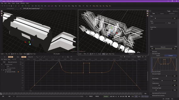
Figure 16-15. Pull tension handle down to create straight slope
Next, pull the outside spline tension handle up for each of the top spline points, creating a shape that looks like the Batman logo, at least on the outside (wings) part.
This adds a professional result at the top of the inner trough curvature, as you can see in Figure 16-16, and shows you can create a curved outer bevel, called a chamferin 3D modeling terminology. Also notice that Fusion 8 added points and edges to the 3D text mesh object to approximate this curve, which must be using “smoothing groups,” as it looks infinitely smooth in View1 (the text 3D node view) but faceted in View2 (the merge 3D node view). Smoothing groups tell your renderer where to smooth, and where to have seams, in the surface geometry topology rendering.
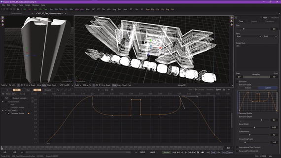
Figure 16-16. Lift outside tension handle, creating a Batman-esque curve
Be sure to experiment with 3D text node modeling features as well as with the spline editor, as both are important to VFX.
Summary
In this sixteenth chapter, we took a look at how to do 3D text spline modeling in Fusion 8 for use in titling sequences for your VFX projects. We looked at how to set algorithm parameters to have Fusion 8 model “classic” 3D text objects, and then looked at how to use splines to create more complicated custom 3D text elements, as well as how to combine the two into one VFX project.
In Chapter 17, you will learn more about how to go about creating 3D text-titling animation effects using Fusion 8.