Now that you have an understanding of the fundamental concepts, terminology, principles, and methods of data footprint optimization for 2D digital imagery, digital audio, digital video, and vector digital illustration new media content for VFX project pipelines, it is time to get into the more complicated area of 3D new media assets that can be used with Fusion’s advanced 3D feature set.
Fusion uses an open source, real-time 3D vector rendering platform called OpenGL, which stands for Open Graphics Library. Unlike SVG, which is relatively simple in comparison with OpenGL, I can’t cover 3D in just a couple of chapters—or even within a couple of books, for that matter. I’ll cover most of the topics that are important for 3D- and GPU-centric Fusion 8, however.
In this chapter, I’ll give you as much of an overview of 3D as I can, but it is far more expansive than your 2D new media assets, and not just because it has the third dimension (depth) or fourth dimension (animation), which digital video and digital audio also have. Vector 3D can be used to create photorealistic environments out of thin air. It has been primarily driven by the 3D game industry as well as by the Hollywood film industry. You can take advantage of all these 3D advancements in Fusion.
We’ll look at the basic concepts, principles, and formats used in 3D vector images, 3D animation, 3D modeling, 3D texture mapping, 3D particle effects, 3D physics simulations, character animation, and all of the similarly complex, 3D-related topics.
3D New Media Assets: 3D Vector Content
3D vector assets are primarily comprised of 3D vector geometry, which is made up of vertices in 3D space that are surfaced with raster images, which you learned about in Chapter 2. 3D can be animated using keyframes, which we covered in Chapter 5 and will also cover in this chapter. Characters can be created in 3D by defining skeleton rigging, facial animation, lip-syncing, skin, muscles and cloth.
Everything we have covered in the first five chapters is available for use in 3D, and therefore in Fusion VFX pipelines. Digital images can be used to create shadersthat texture map a 3D model’s geometry. Digital video can provide animated texture maps, and SVG geometry will be used to create 3D geometry using 2D. Or, SVG can be rendered on 3D surfaces for texture map effects, such as transparency (opacity) maps, and digital audio could be used for sound effects or to allow your 3D character to speak.
Let’s start from the vertex on up, like we did with 2D vector illustration. I will show you various attributes that take a 3D asset from being 3D geometry to being a 3D model to being a 3D hierarchyto being a 3D animation to being an i3D object. This is the least commonly used new media asset type to be found in HTML5 (websites, HTML5 OSes, tablets or smartphones) using WebGL 2.0. Android 7 uses OpenGL ES 3.2 and a new Vulkan rendering engine, and Java 7, 8, and 9 via JavaFX all use OpenGL ES 3.1.
The Foundation of 3D: The Geometry for the Model
The lowest level of 3D new media assets is, just as with 2D SVG new media, the vertex and its connection with other vertices. With 3D, connections between vertices become more complicated, not only because these occur in three dimensions, but also because 3D introduces triangular facescommonly called polygons, or polys, or rectangular facescalled quadrilaterals, or quads. The connections between vertices are called edges. Faces are created using vertices and edges. Before 3D geometry is texture mapped, it’s referred to in the 3D industry as a mesh or a wireframe, since that is what it looks like before it is texture mapped or skinned using digital imagery. We will cover this in the next section.
3D Starts with Data Points in 3D Space: Origins of the 3D Vertex
Just like the 2D vertices—anchor points, as they’re called in Illustrator, or path nodes, as they are called using Inkscape—the vertex is the foundation of your 3D geometric or 3D organic modeling . Just like 2D polygons use straight lines, 3D polygonal or geometric models also use straight lines, whereas 3D organic models use 3D algorithmic curves defined using NURBS, Catmull-Rom Splines, Bézier Splines, or Hash Patches curve algorithms. A vertex defines where your model’s infrastructure, whether that is edges or splines, is going to be located in 3D space. 3D scanners generate “point clouds” of vertices, and the Alembic format supported in Fusion tracks vertex characteristics, including 3D spatial animation. Alembic is a data format that defines all of its 3D data using vertices, and is supported in Fusion 8.
In 3D geometry, vertex data can hold surface colordata, surface normals data , UVW texture mappingdata, as well as the vertex X,Y,Z location data. This is similar to pixels for 2D, which hold X and Y data, RGB color data, and alpha channel data.
Connect the 3D Vertices: Edges Connect the 3D Vertices
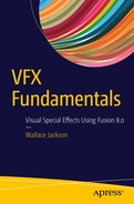
3D geometric models use something called an edgeto connect two vertices. An edge is a vector, or straight line, so it looks like the edge of a razor in 3D space, as you can see in Blender in Figure 6-1. Three edges are needed to form polygons, and four edges are needed to form quads. Polygons and quads are what are called faces, and we’re going to cover those in the next section. When you’re modeling 3D geometric objects, you can select components of the model, such as vertex, edge, or polygon.
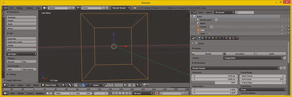
Figure 6-1. Blender 3D geometry showing eight vertices and twelve edges
If you’ve created your 3D geometry using a more advanced, organic, spline-based model paradigm, such as that used to create characters, like NURBS using MoI 3D, or quads using SILO 2.3 (which is only $159), or using Hash Patches in Animation:Master (which is only $80), then you will then need to “decimate” your model into polygons (triangles). This is what the GPU hardware used with Fusion does during 3D rendering if you are using spline-based or quad-based 3D models. Fusion does support quads, NURBs, and splines internally, as it comes very close to being a full-fledged 3D software package itself, as you will see during the course of this book.
The algorithmic process of decimationfrom other spline- or patch-based representations of 3D geometry into triangles or polygons turns infinitely smooth curves used in these modeling paradigms into a data-heavy collection of triangular faces that have straight edges and have to use more (and smaller) triangle data to approximate smooth curves. This works for VFX pipelines that are rendered out to frames, but not in interactive games.
Decimation is done by using a decimation or smoothnessnumeric factor via a slider or dialog setting. This will be the decimation function inside of the 3D software, or it can sometimes be supplied in a File Export function , which outputs the spline-modeling format from your curve-based modeler into a polygonal geometric model format. A great example of this can be found in the Moment of InspirationV3 NURBS modeling software. Now, let’s take a look at how polygons, quads, and splines form 3D surfaces.
Surfaces: Three Edges Form a Polygon, Four Edges Form a Quad
Once you have three edges together in the form of a triangle, you have a polygon. This can be used as a surface and can host a skin, or texture, to make the 3D data look more realistic. The rule of thumb is, the more uniform (square) a triangle is, the better it will render. Slivered, or long and thin, triangles, may cause rendering artifacts, or visual anomalies, but often do not. You feeling lucky? Then use slivered polygons. Modelers often prefer modeling with quads and keeping them as square as possible using quad modelers such as Silo 2.3 from NeverCenter, which is only $159 and can be used for 3D character modeling.
Character modeling is usually accomplished using organic spline modelers, such as SILO 2 or Hash Animation:Master, which uses highly efficient, proprietary Hash Patchcurve algorithms.
Once you have a surface—which, for use on devices using OpenGL, will need to be a triangle—you will have also defined your surface normal, which you will be learning about next.
Direction a Surface Is Facing: The Concept of Surface Normals
The function for this surface normal is fairly simple. A surface normal tells a rendering engine the direction a surface is facing—inward or outward. The same logic would apply to a vertex normal; it would show the rendering engine which side of your 3D geometry to process for surface rendering.
If you know how to turn the “show normals” feature on in the 3D software, you can see the 3D face surface normals, which should be displayed at the exact center of the face, as you can see shown using tiny short lines in light green in Figure 6-2.
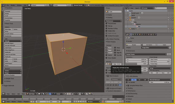
Figure 6-2. Displaying face normal, as short green line on face
As you can also see in Figure 6-2, two of the normals shown are actually aligned with the x (red) and y (green) axes, which intersect the cube at 90 degrees. Your axis guide, in the lower left corner of the 3D Edit Mode view, shows you which axis is x and which is y and which is z.
There are buttons in Blender for showing vertex normals, which point outward from the vertex, so for this model vertex normals point out diagonally from the corners of the cube at 45 degrees, the exact opposite result from the face normals, which point straight up, at 90 degrees, from the center of each face.
If the normals for this cube geometry had been pointing inward instead of outward, this cube would not be visible at all when rendered. There’s a flip normalsoperation (algorithm) in 3D software that is used to reverse your normal directions. This is done for the model universally; all normals are flipped 180 degrees. If you ever can’t see your 3D model in Fusion, use the flip normals feature to correct this file export anomaly.
Flip normals would be utilized when you render the scene and your imported 3D object is not visible after you render the scene. This is almost always because a 3D import utility points (flips) the surface normals for the imported 3D geometry in the wrong direction. An exporter from a 3D modeling tool might have exported the surface normal in the wrong direction, relative to the software you are importing them into. This is a fairly common occurrence, so expect to use flip normals regularly if you are going to be working with 3D new media assets in VFX software.
If you need two-sided geometry, like a house, for instance, where the 3D geometry has to render from the outside as well as from the inside because you have to be able to navigate through the models (this is common in virtual worlds, for example), you will have to create geometry faces that are double-sided polygons. You’ll also need to apply a double-sided texture map, which I’ll be covering during the next section, which covers 3D texture mapping concepts and terminology.
It is important to note that for i3D, using double-sided geometry and double-sided textures will require significantly more real-time rendering-engine processing by your CPU and FPU. This is because Interactive 3D, such as is found in game engine applications (as well as in the user interface for Fusion 8) renders the 3D geometry, textures, and animation in real-time. This requires a powerful GPU, which is why I recommended nVidia and AMD GPUs in Chapter 1 when we covered hardware requirements for Fusion 8.
Smoothing a Faceted 3D Surface: Using Smoothing Groups
You have seen 3D models that are rendered as solid (instead of wireframe) but look like they are chiseled; that is, you can see the polygons (faces) rendered as if they were flat, as in Figure 6-3. This is often called flat shaded, and no smoothing is being applied by the rendering engine. If you render the same geometry with smoothing turned on, this effect disappears, and the 3D geometry looks like it was intended to look, which is infinitely smooth, like it was created using splines, when it is in fact using polygons. It is more efficient to have your rendering engine do the smoothing than to have a ton of mesh (polygon) data. The renderer applies smoothing using something called a smoothing group, which is applied to each face to tell the renderer when to smooth between two faces, and when not to smooth between faces, which leaves what is commonly referred to as a seam. A smoothing group uses simple integer numbers. If the numbers match on each side of an edge—that is, for each adjacent face on the opposite side of that edge—it renders as a smooth color transition. If the numbers are different, it renders a seam, and the edge will be clearly visible, as color gradients on each side of that edge will be different, so the color gradient is not seamless across the two faces (polygons).
Figure 6-3. Set faceted shading via Transform ➤ Shading ➤ Flat
In some 3D software packages, such as Autodesk 3D Studio Max, you can see this smoothing group numbering schema right in the user interface. In others such as Blender, the numbering is hidden and the smoothing groups function is exposed using commands such as Mark Seam, Clear Seam, Mark Sharp, Clear Sharp, and so on. These can be found in the Blender Edges Menu.
Some 3D modelers (people, not software) will make the mistake in Blender of trying to expose a seam or a sharp edge in the 3D geometry by actually splitting an edge in the 3D geometry itself. This will achieve the right visual effect, but might cause a problem down the line during a 3D geometry topology refinement.
The term topology references how the surface of the mesh for your model is designed—whether it uses triangles, quads, or splines, for instance—and how these come together, especially at the seams of where model components attach, such as arms to a torso, legs to the waist area, or head (neck) onto shoulders.
Having to split geometry edges to achieve the seam can be avoided by instead using the Mark Seam, or a Mark Sharp, edge-modifier operation in Blender. This should affect only the smoothing group—that is, how geometry is rendered—and not the model topology. As you can see, 3D is a very complex media type.
These Mark Seam, Clear Seam, Mark Sharp, and Clear Sharp Blender seam modifiers are smoothing-group-based and therefore achieve their smoothing (or edge-seam) effect without actually affecting the 3D geometry topology itself.
A modifier in Blender is applied right before rendering and therefore doesn’t affect the actual mathematical topology for the underlying 3D geometry. If you are familiar with the term topographyused in mapping, know that topology is very similar but is a 3D term referring to how the surface for 3D geometry has been constructed during a 3D modeling process.
Using the Blender modifier is always a more flexible i3D content-creation approach as it applies a smoothness, or other desired effect or result, at the rendering-engine level, and not at the 3D geometry–topological level. Decimation would perform this geometry smoothing at a topological level directly on the mesh geometry. Using a modifier will leave a 3D mesh intact, and is ultimately simpler. Fusion 8 works in much the same way.
You can apply smoothing to a 3D model globally—that is, to all faces at the same time—by using the Transform panel and the Shading panel area, and then clicking on the Smooth button, as is shown in Figure 6-4. This applies the smoothing groups to the entire model, resulting in a smooth surface color gradient.
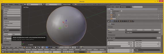
Figure 6-4. Set smoothing using Transform ➤ Shading ➤ Smooth
Next, let’s take a look at how to apply a skin to your mesh geometry surface using something called texture mapping.
Skinning the 3D Model: Texture-Mapping Concepts
Once your 3D geometry, which is the foundation for your 3D model, is complete, you can apply texture mapsto it to create a solid appearance for your 3D model. Texture maps can also be used to add detail and special effects to a 3D model, making it appear more realistic. If you are wondering what the difference is between 3D geometry and a 3D model, 3D geometry is just the mesh or wireframe, whereas a 3D model should have texture maps already applied. If you purchase third-party 3D models, you expect them to look like what they are supposed to be when you render them complete with texture, instead of just being flat gray, which is what a rendered model will look like without texture maps applied, as can be seen in Figure 6-4. Luckily, Fusion has the ability to texture 3D models!
Texture Map Basics: Channels, Shading, Effects, and UVW Maps
Texture mapping is almost as complex an area of 3D as creating topologically correct geometry is. In fact, each area of 3D is equally complex, which is what makes 3D the most complex new media type overall, with the possible exception of visual effects! This is why feature films employ 3D VFX artists to specifically focus on and handle each of these areas we are looking at in this chapter. Texture mapping is one of the primary areas in 3D new media asset production that is able to use 2D vector as well as 2D raster image and video assets.
It’s important to note that there is also a more complex area of 3D texture mapping that uses 3D texture algorithms. It is commonly termed volumetric texturing, and it uses algorithms to create true 3D texturing effects that go all the way through the 3D object as though it were solid and not hollow mesh. That is, it is a 3D object that requires double-sided texture maps.
A basic concept behind texture mapping is taking assets such as those you learned about during the first five chapters and applying them to the surface of 3D geometry. The question is, how do we align these to a model?
This is accomplished by using U,V,W mapping coordinates. These 3D mapping coordinates show how you want the 2D image (plane) oriented to, or projected on, the 3D geometry surface topology.
UVW is different than XYZ, but they represent the same dimensions (width, height, depth). Letters other than XYZ are used to avoid confusion, so they used the three letters in the alphabet before XYZ; that is, UVW. You use UVW to reference applying your texture map orientation, and you use XYZ to reference your 3D geometry orientation.
You can add more than one texture map to the surface of your 3D geometry. This is accomplished using texture channels.
These are analogous to the color and alpha channels that you use in 2D images to define each pixel’s characteristics. OpenGL ES platforms, such as Android, HTML5, and JavaFX, currently support four of the most important texture channels. Fusion 8 supports numerous texture channels, which you’ll see later on.
Primary texture channels include the diffuse texture map (basic RGB color values), a specular texture map (where surface looks shiny or dull), an illumination texture map (called a glow map ), and the bump texture map .
3D software supports other advanced texture map channel types used for additional texturing effects. To bring them into Fusion, you will want to use the FBX or Collada 3D file format.
Baking texture maps involves rendering all the texture’s channels into a primary diffuse texture map, since this is what devices support. This provides a similar visual result to what you will get when you render your 3D object in your 3D package or in Fusion 8, and you want to use that texture map in OpenGL.
As you can see in Figure 6-5, Blender uses a SceneGraph, just like most modern day i3D software packages will. In fact, Java’s JavaFX offers the same SceneGraph functionality. A Scene Graph is a visual graph of the 3D scene construction, as seen on the right in Figure 6-5.

Figure 6-5. Using the Blender 3D SceneGraph to apply a gold texture map and shader
This sphere geometry and its texture mapping are grouped together in the SceneGraph hierarchy, which I have expanded for you on the top-right of Figure 6-5. This texture-map definition contains several texture channels; in this case diffuse (color) and specular mapping. These control the surface characteristics—such as shininess, metallicity, and similar looks—that you want in order to achieve your photorealistic, 3D-rendered output result.
As time goes on, OpenGL ES 3 could add even more texture channel support. This would give developers increased visual flexibility regarding their 3D new media asset usage, as transparency areas (opacity maps) and surface details (normal maps) are two of the most important areas of advanced texture mapping support that needs to be added to Android, Java, JavaFX, and HTML5.
A collection of texture channels, and any code governing these channels’ relationship to each other, as well as how they will be composited together and applied and rendered relative to each other, is called the shader definition.
Shaders are also commonly referred to as materials in the industry. We will be covering shaders and shader languages in the next section of this chapter, as this is another specialized (and complex) area of 3D and VFX project design for application development. As you can see, there are a lot of layers to VFX and 3D production, and, in fact, where shaders are concerned it can get fairly complex, as it involves blend modes and channels.
Shader Design: Shader Channels and GLSL Shader Language
As are each of the areas of 3D object creation covered in this chapter, texture-map shader designis an art form, in and of itself. Hundreds of shader artisans work on 3D movies, popular console games, VFX, television shows, and the like ensuring that the shaders used to texture or skin the 3D geometry make the resulting 3D model look as real as possible. This is often the primary objective of 3D and i3D—to replace more expensive video camera shoots and subsequent re-shoots by creating virtual worlds and having computer render farms create all the camera movement for you, then turning the 3D data into pixels (imagery), frames (video), or experiences (games, apps).
The basic shader is made up of a series of vector shapes and raster images, or algorithmic, volumetric textures, held in different types of texture channels. These texture channels use the vector and raster assets to apply various types of effects, such as diffusion(RGB color channels), opacity (transparency), glow (self-illumination), specularity(surface characteristic), environmental(surroundings), bump (height), normal (topology ), and similar detail-effects channels that increase photorealism.
On top of this, advanced shader languages, like the Open GL Shader Language, or GLSL for short, use code to define just how these channels will interrelate with each other, how to apply or process the data contained in these channels, and how to perform other, more complex applications of the data within these channels based on complex factors such as time, orientation, or an X,Y,Z position in 3D space.
The complex nature of shaders also means that a render-time processing of the shader is more time consuming, and more processing-cycle consuming, the more complex a given shader becomes.
This is probably the primary reason OpenGL ES3 currently supports the four basic, easiest-to-process shaders. As hardware becomes more powerful (4- or 8-core CPUs in consumer electronics products), OpenGL ES will probably add in the last two important shader channels: opacity (alpha channel) and normals mapping.
Once texture channels are defined inside of the shaders, you will need to orientthe 2D assets to the 3D geometry, which is done using texture mapping coordinates. Each channel will have its own coordinate system by which to apply each of the effects to the mesh (geometry) as needed to achieve the desired effect.
This is accomplished using UVW mapping, which we’ll cover further in the next section before we move into the fourth dimension and cover 3D animation principles and terminology.
Texture Map Orientation: Projection Types and UVW Coordinates
It is important to align the detail features in your 2D texture map channels—especially the foundational diffuse color channel, as it paints or colors the surface of your object—to your i3D geometry correctly. If you don’t do this correctly, some fairly odd, or at least visually incorrect, results appear when the 3D object is rendered. The alignment needs to be done in 3D space—for texture mapping this is U,V,W—especially with a volumetric “true 3D” texture, and also for 2D textures, in order to define how they will project onto, on top of, or envelop around i3D geometry.
One of the easier ways this can be done is by applying a texture map projection typeand its related settings. This will then automatically set your UVW mapping numeric values for you. These UVW map coordinate values will define how your 2D imagery plane maps onto the 3D geometry in 3D space. This provides your “mathematical bridge” between your 2D space and your 3D space. UVW map floating-point values can be set or tweaked manually in order to fine-tune the visual result of the texture mapping.
The simplest type of projection is planar projection, as a plane is a simple 2D square. You would visualize this type of mapping as if your 2D texture map image were in front of the 3D object and you were shining a light through it; it would look like the colors in your diffuse texture map were projected onto the 3D object. A planar projection is also the simplest for the computer to process, so use this if you can get the result that you will need for the VFX project pipeline. You can also create planar mapping inside of Fusion 8.
Planar mapping is often used for static 3D objects, such as rendered 3D imagery. Once you move the camera around to the sides of the 3D model, this type of projection mapping will not provide photorealistic results for dynamic (animated) projects.
Camera projectionis very similar to planar projection, as camera projection projects the texture from the camera lens onto a 3D object surface much like a slide projector would do. The projection is 100 percent parallel to the front of the lens. This should be used for projecting video backgrounds onto your scene so that you can model, or eventually animate, your 3D assets in front of the projection. If a camera moves, camera projection mapping will stay parallel with the front of your lens. This is sometimes termed billboard mapping mode (or billboard projection).
Your next simplest type is cylindrical projection, which provides more of a 3D application for your texture map than do the inherently 2D planar or camera projection of a texture map onto a 3D object from a single direction. A cylindrical map surrounds the object in your up and down (a 3D z-axis) dimension, projecting your image all the way around your object! If you walked around the 3D object, there would be unique texture details in another dimension, which planar or camera projection do not provide. Make sure your texture maps tile seamlessly along their y-axis!
An even more complex projection mapping type is called a spherical projection. This can provide an even more complete 3D application of your texture map than the cylindrical projection will. Spherical projection attempts to address all three—x-, y-, and z-axis—projection directions. Again, you want to make sure your texture map is tileable to avoid any visual seams.
Similar to a spherical projection is a cubic projection. This is like having six planar projections in a cube format and gives a result similar to spherical projection. It uses a special cubic texture mapdata format.
When you apply the cubic projection mapping type to your i3D object, the object’s faces are assigned to a specific face in a cubic texture map, as you may have guessed. This is based on the orientation of each of the 3D object’s polygon normal, or by the proximity of the face to the cubic texture map (coordinate) UVW mapping space. The cubic texture is then projected from the faces of the cubic texture map using planar projection methods.
If you use volumetric textures, the spatial projection is a three-dimensional, UVW texture projection that is projecting through the 3D object’s volume. It is typically used with procedural or volumetric textures, or textures that need to have an internal structure, such as wood, marble, sponge, agate, and so forth. If you slice a 3D object or transform texture map coordinates relative to the 3D object, different parts of the volumetric or procedural texture will subsequently be revealed.
There’s also a simpler texture mapping method called UV mapping (no W dimension). This applies your textures in two dimensions, instead of three, and is easier to process as it has less data. You can also use Fusion 8 to texture map your imported model. Now, we are ready to take a look at some 3D animation concepts.
3D Animation: Keyframes, Motion Curves, and IK
After you have created your 3D geometry and texture mapped it using shaders and UVW mapping coordinates, you may want to make it move in some fashion, such as flying a helicopter model. Concepts you learned for digital video assets in Chapter 3 apply equally as well to 3D animation assets, as you might guess, as both use keyframes. 3D software packages have what are generally termed “track editors,” which allow you to add keyframes and a motion curve to tracks. In fact, Fusion has exactly the same advanced functionality for creating visual effects, as you will see during this book. Each track will relate to a 3D model, and if a 3D model uses sub-component grouping, then there can be tracks for groups and sub-groups as needed to achieve any complex animation or simulation necessary for your VFX project, application, game, or i3D virtual world.
Simple Linear Animation: Tracks, Keyframes, Loops, and Ranges
The simplest type of 3D animation, and 2D animation for that matter, is linear animation, which is useful for many types of 3D animation. Linear animation will use the least amount of processing power, so it is the most efficient. If you can use linear animation to accomplish your 3D animation objective, use the fewest number of tracks you can and the fewest number of keyframes, as this will use the least amount of system memory.
If animation motions are repetitive, use a seamless loopinstead of a long range containing duplicate keyframe data. One seamless motion loop can take up less memory than a long range, especially when that range contains multiple copies of the same motion, which would be heavily redundant. So, using loopingis a great optimization principle where linear 3D animation is used.
Next, let’s take a look at some of the more complex types of animation, including those that aren’t linear. They will not be in a straight line, with evenly spaced keyframes. We’ll also take a look at character animation and procedural animation, which is used for things like physics simulations and particle systems. Fusion 8 has advanced features for all of these powerful visual effects capabilities, and can bridge to 3D software for any capabilities that it doesn’t feature natively.
Complex Non-Linear Animation: Motion Curves and Interpolation
A more complex type of non-linear animation, which is less regular and often looks more realistic, especially where human motion and simple physics simulation is concerned, will implement a motion pathfor the animated 3D object or element (a sub-object in your hierarchy) to move along. To add even more complexity to the motion along that path, it is possible to use a motion curveso that the movement itself can speed up or slow down, simulating things like gravity, friction, or bouncing. The mathematical algorithms that are represented visually using these motion curves are called interpolators. JavaFX has an Interpolator class that contains a wide variety of the most standard (yet quite powerful, if used effectively) motion curve algorithms, and Fusion features this capability as well, as you may have guessed. We will get into Fusion in the next chapter.
A good example of non-linear, irregular-motion keyframing would be a rubber ball bouncing down the windy road. The curved path of the road would use a motion path to make sure the ball stays on the road curvature and that the ball floor conforms to the slope (angle) of that road. The bouncing of the ball should use a motion curve, also called a motion interpolator, in order to make each bounce look more realistic regarding the timing of the acceleration or deceleration of its movement through space. In this case, this is how your ball should react to the ground.
Complex physics simulations could be done using keyframes if you wanted to spend months of your time, as could character animations. However, it is actually easier to write algorithms and code routines to achieve this than it is to lay down motion paths, curves, or keyframes to try and simulate these phenomena.
Therefore, we will cover character animation principles and procedural animation principles next, as we are progressing from the less advanced concepts to more advanced concepts.
Let’s get an overview of character animation next, as it is the next type of 3D animation that is supported in Fusion 8.
Character Animation: Bones, Muscles, Rigging, and IK
An even more complex type of animation is character animation, and character animators are one of the most popular positions on a 3D film, game, or television content production team. Character animation involves a number of complex layers, including setting up bonesusing inverse kinematics(IK) to control a skeletonthat attaches to the musclesand skin, which attach to clothing featuring cloth dynamics simulations—so things with character animation are about as complex as they can get without using code, which as you now know is called procedural animation. Fusion can bridge over to these features using FBX.
At the lowest level of character animation you have your bone, which uses an inverse kinematics algorithm. This controls the range of movement (rotation) so you don’t have elbows that bend the wrong way or heads that spin around like in The Exorcist.
Bones are connected together in a hierarchy that forms a skeleton. This is what you will animate (keyframe) later on to bring a character to life, and is commonly termed rigging in the Character Animation. You can also simulate muscles and skin by attaching these to each adjacent bone and defining how a bone movement should flex each muscle and stretch the skin for the character. The muscle flexing and skin deformations are complex algorithms as well, just like the IK algorithm that controls a range of movement for the skeleton’s component hierarchy.
There is also an area called cloth dynamics that then controls how clothing worn by the character would realistically move, or deform. This is also controlled by algorithms guided by control settings, which are applied by artisans who set up the cloth dynamics rigging.
As you can imagine, setting all of this up can be a very long and complex process, and is an area of character animation summarized using the general term rigging.
Fusion 8 doesn’t have many character animation features, but does use the Alembic, Collada, and FBX formats to be able to seamlessly connect with character animation software, such as Autodesk 3DS Max and Maya, Lightwave, and Cinema 4D XL.
As I have mentioned, character animation and rigging is its very own job area if you plan to work on rigging for the film, VFX, or console game industry. The area of vector 3D is complex, so each of the areas we are covering is its own specialization.
Procedural Animation: Physics, Fluid, Hair, and Particle Systems
The most complex type of animation is procedural animation, because it needs to be done 100 percent using algorithms; all control specifications done by the artist are actually done in the code for the algorithm. In 3D packages this is done using C++, Python, Lua, or Java; Fusion 8 currently uses Lua and Python. The procedural 3D animation for Android applications would be done using a combination of Java and JavaFX, and HTML5 would use JavaScript.
This is the most complex and also the most powerful type of 3D animation, and it is the reason why “procedural animation programmer” is currently one of the more popular 3D job openings in the 3D film, games, VFX, IoT, and television production industries.
You are beginning to see why i3D is the most complex new media genre, along with VFX design using Fusion 8, and sound design using Reason 8.3.
There are a lot of features in 3D modeling and animation packages such as Blender, A:M, Silo, or 3D Studio Max that were actually procedural animation algorithms at one time. These are eventually recoded via the user interface that allows artisans to specify control settings so that all users, not just coders, can use them. These become what is popularly termed a plug-in.
The plug-ins expose a user interface to the user in which to specify parameters. These parameters control the result of a procedural animation once it is applied to 3D models or to a complex 3D model hierarchy created using the 3D software. This same paradigm also applies to VFX procedural algorithms, which eventually are made into plug-ins and sometimes into hard-coded VFX features that actually appear on the software menu structure as part of the program itself.
Examples of procedural animation algorithm–simulated and –controlled features—many of which include real-world physics simulation support—that are often plug-ins added to advanced 3D animation software packages include 3D particle systems, fluid dynamics, cloth dynamics, rope dynamics, hair and fur dynamics, soft body dynamics, rigid body dynamics, video motion tracking, and many other advanced features that require algorithms in order to be implemented with a reasonable amount of effort. 3D as well as VFX production is all about leveraging the computer processor and memory to create compelling content!
Summary
In this sixth chapter, we took a look at vector 3D concepts and terminology. We looked at components of 3D mesh geometry and how adding texture mapping makes this a complete 3D model. We looked at UVW mapping and how to easily apply this using projection mapping, at what a shader and shader language is, and at different types of 3D animation, from simple linear animation to complex animation types such as character animation and procedural or algorithmic animation. We saw how much complexity this area of 3D new media has due to its ongoing support of advanced console games, VFX pipelines, and feature film and television production.
In Chapter 7, we’ll start to learn about Fusion 8 features and user interface and how to create a VFX project’s foundation, which we’ll be building upon during the rest of the book.