
It’s time to build your final bot for the exploration team. If you’ve chosen to build your own version of the PushBot , I’m confident it won’t look like the one in Figure 19-1. My version of the PushBot has some unique features that I’ll cover in this chapter, so if you’d like to build the version shown here, let’s get started.
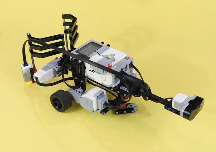
Figure 19-1. The PushBot is a fun bot to experiment on. Your completed bot will have six wires in total ➤ three motors and three sensors.
Note
If you’ve built a unique version of the PushBot, please send me a picture. My web site address can be found in the Introduction near the beginning of the book.
Step by Step
I’ve divided the PushBot’s building instructions into three sections. The first section covers the Jaw Cage mechanism with the medium motor. The second section shows you how to assemble the neck/Infrared Sensor assembly with its rear caster wheel, and the third section gives you the steps to build the main body of the PushBot, including the two main motors and drive wheels.
I’ll continue to add comments for figures that might be a little tricky. And this next “Engineering” section is a sidebar that explains the thinking that goes in to creating instructions like these. If you want to read it later, that’s okay! You can start building right now.
Engineering: The Difference Between Designing and Explaining
This chapter’s description of how to build a PushBot needs to be as simple and straightforward as possible, so you can easily make a copy of this robot. But that is a different problem from designing a bot. In this case, I started the design by fiddling with the medium motor and a cage assembly, using the rounded gears at a 90-degree angle. I based it on an earlier design that used a large motor. But since I am using the retail EV3 kit, I have two large motors and one medium motor. So I started working on that problem first. I knew that designing a driving base would be fairly easy, but I had never designed a jaw assembly like this one.
“Designing with your hands” is a different mental process than sitting down with a piece of paper or design software on a computer screen. It’s a different kind of thinking. So I picked up the medium motor, some axles, all four rounded gears, lots of pins, and a large frame piece. The main problem was how to convert the medium motor’s “sideways-ness” into the “back-and-forth-ness” needed to work a pair of jaws. That is the design you see here. I made 15 or 20 changes as I worked through it. When you’re doing this, sometimes a design seems to say, “This is elegant, makes good use of the materials, and solves the problem.” The experience is as much esthetic as it is engineering.
But to create an explanation in this chapter, I took the completed robot and studied it on its own. I asked, “What’s the easiest way to take this apart so someone else can understand it? And that meant dividing it into three or four sub-assemblies, each of which had its own story. (This kind of thinking is definitely accessible to a young person. I wrote my first instruction manual in second grade , when we got a new train set. We had an old train set that we were donating to charity, so I wrote a set of instructions how to hook it up.)
First Section: Figurine Jaw Cage/Medium Motor Mechanism
Figures 19-2 through 19-27 provide the steps for constructing the Figurine Jaw Cage/medium motor mechanism. Start with the motor and components you see in Figure 19-2. The completed mechanism is shown in Figures 19-25 through 19-27. It can be helpful to skip ahead to see what you’re about to build.
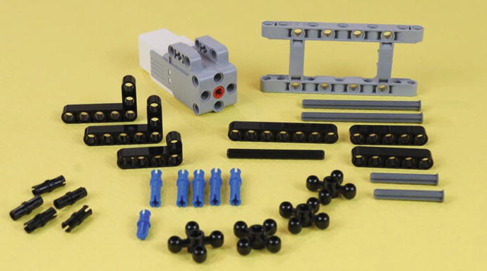
Figure 19-2. These are all of the parts of the cage mechanism, except the jaws themselves. These parts will take you all the way through Figure 19-15. The long nailheads are eight holes long. The short nailheads are four holes long. The black axle is six holes long.
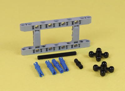
Figure 19-3. Separate out this smaller group of parts. Connect them as shown in Figure 19-4. In that figure, the pins and axles are partially inserted to make them easy to see. This is the six-hole axle.
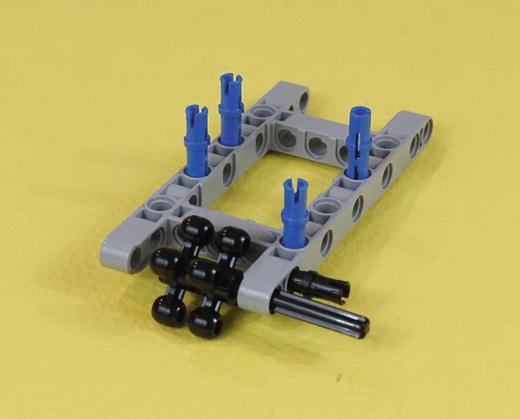
Figure 19-4. In goes the axle, through the two rounded gears . Press it the rest of the way in, as shown in Figure 19-5. Also press the four long blue pins and one short black pin all the way in.
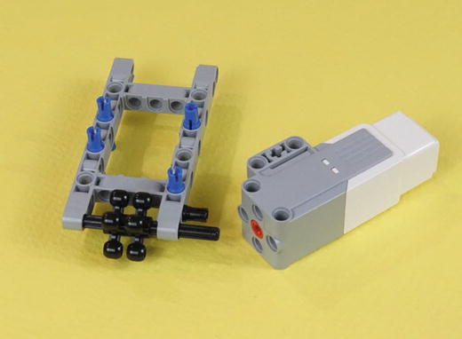
Figure 19-5. Now let’s get that Medium Motor mounted. The axle goes into the red motor hole, and that black pin engages the front motor mount.
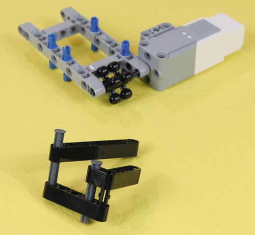
Figure 19-6. More parts from Figure 19-2. A seven-hole beam, a five-hole beam, and a short L piece. Two four-hole nailhead axles and a black pin complete the bottom-axle sub-assembly.
Press the nailhead axles all the way in and then put the sub-assembly underneath the motor-frame assembly . In Figure 19-7, we see them partially pressed into the long blue connectors. They are pressed all the way in when we get to Figure 19-8.
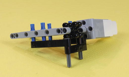
Figure 19-7. The bottom-axle sub-assembly engaging with the motor assembly. Press the nailhead axles all the way in. In this view, the bottom-axle sub-assembly is pressed part way onto the long blue pins.
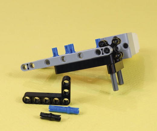
Figure 19-8. The bottom-axle sub-assembly in Figure 19-7 is pressed all the way onto the blue pins. Three more parts from Figure 19-2 ➤ a black short pin, a long blue pin, and a large L-beam.
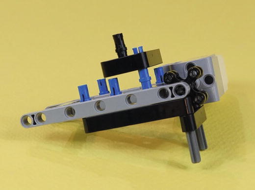
Figure 19-9. The corner of the large L-beam engages the blue pin as shown. The black pin goes in just to the left of the blue pin. The long side of the L-beam points away from you. The three-hole short side is directly facing you. Pressing this sub-assembly down gets you to Figure 19-10.
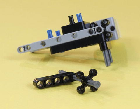
Figure 19-10. Three more pieces from Figure 19-2’s parts collection. A long nailhead axle, five-hole beam, and a rounded gear. Press the axle all the way into the gear and beam.
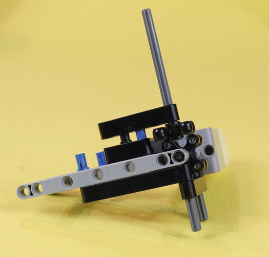
Figure 19-11. Now set the five-hole beam with its axle assembly on those two available pins, as shown. You’ll press them down in Figure 19-15.
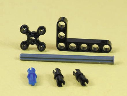
Figure 19-12. Gather these last six parts from Figure 19-2. They go together as shown in Figure 19-13.
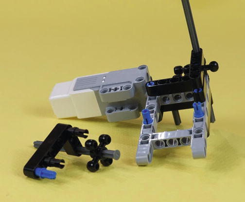
Figure 19-13. The final six parts shown partly inserted. In Figure 19-15, you’ll press them all the way in, including the nailhead axle.
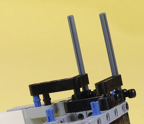
Figure 19-14. Close-up of how the large L-beam with axle and gear is placed on the medium motor and the other frame pieces. This L-beam and the five-hole axle assembly from Figure 19-11 are now ready to be pressed all the way down.
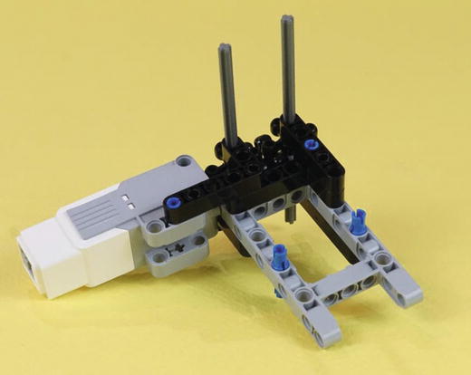
Figure 19-15. Press the beams all the way down. This medium motor assembly is ready for some Figurine Gripper Jaws .
Engineering and the Concept of Stiffness II: Angles, Brackets, and Connectors
You are now at an interesting point . That last L-beam, pressed firmly down on the medium motor assembly, did a lot. It finished the positioning of the gears, made the second long nailhead axle secure, and very usefully added two solid connectors to the medium motor. Before, that motor was held in only by the axle attached to the gears, along with one short pin. You now have a sturdy assembly that can support the jaws and the force of the motor itself. Figure 19-16 shows another view of this assembly.
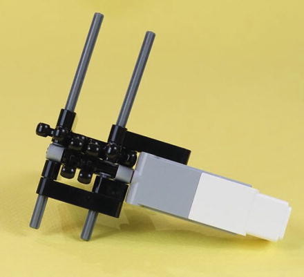
Figure 19-16. The medium motor assembly seen from another side. Bring on those Figurine Gripper Jaws!
It’s worth spending a moment on how this piece is engineered. The angle pieces are the key to the strength of the assembly. Try moving the axles and gears back and forth. You’ll see how sturdily they are mounted to the medium motor. The L-shaped pieces give you strength in two dimensions, and every hole that can be connected to a pin has one. Long blue pins are used as often as possible, further increasing the stiffness and extending the design to three dimensions. If you take a close look at all of the straight beams and L-beams, you’ll see that any set of holes that can have a long blue pin has one. All remaining open holes have a black pin.
We’re going to collect two more batches of parts to finish the last two Figurine Jaws sub-assemblies. The first batch, shown in Figure 19-17, gives us the jaws themselves . The second batch will attach the Color Sensor to the edge of the left jaw. So, let’s make those jaws. As LEGO would have it, we are well provided with some jaw-like pieces of just the right size. Those, along with some axles, will give us a handsome “jaw bite.”
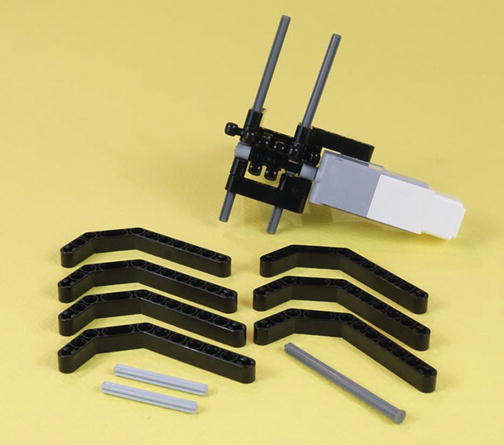
Figure 19-17. These ten new parts will start the Figurine Jaw Cage sub-assembly . Notice the long axle is an eight-hole nailhead. The two short axles have five holes.
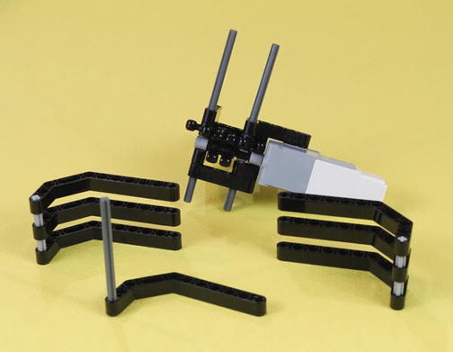
Figure 19-18. The ten parts are partially assembled. The head of the nailhead axle is below the long angled beam.
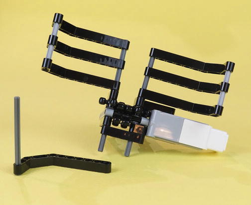
Figure 19-19. Put the two jaw assemblies on the long nailheads at the top. This is starting to look like a Figurine Jaw Cage. More than halfway there…
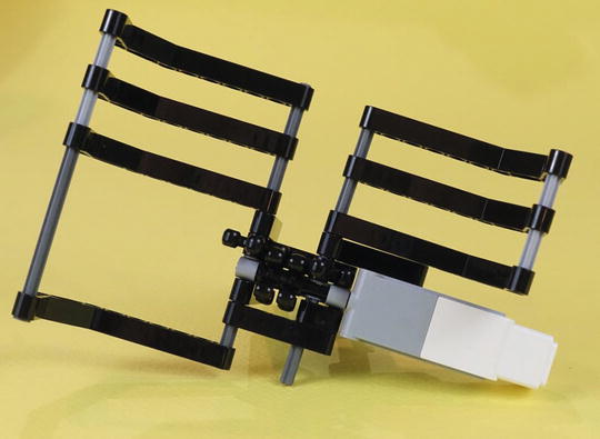
Figure 19-20. Attach that lower jaw piece. Push a little of its nailhead axle into the upper jaw piece. Now the Figurine Jaw Cage is three quarters done. Let’s gather a few more parts to mount the Color Sensor.
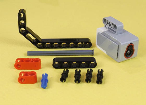
Figure 19-21. These 11 new parts will let you complete the Figurine Jaw Cage/medium motor section, with the Color Sensor attached. That is an eight-hole nailhead axle.
Figure 19-22. Make these two sub-assemblies as shown. Then, squeeze the red parts together so they are centered on the nailhead axle.
As you squeeze the red connectors together, their side holes will wind up at the correct distance to connect with the five-hole beam attached to the Color Sensor . You can see this in the close-up of Figure 19-23.
Figure 19-23. This last sub-assembly is ready to have the pins pressed into their holes. The completed Color Sensor mount is shown in Figure 19-24.
Figure 19-24. The Color Sensor mount, ready to join up with the Figurine Jaw Cage
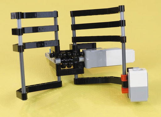
Figure 19-25. The completed Figurine Jaw Cage, shown from the front. Press the long nailhead a little way into the upper angle piece and wiggle the jaw pieces to make them stable and symmetrical.
This is a relatively complex assembly. It can be helpful to have other views, as you can see in Figures 19-26 and 19-27. When you’ve played with the motor and gears, and generally basked in the satisfaction of having made a cool part, set it aside and commence working in the second section. You will build the Neck/Infrared Sensor assembly with a small caster wheel for the rear.
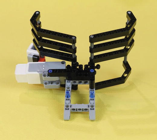
Figure 19-26. The completed Figurine Jaw Cage, seen from the rear
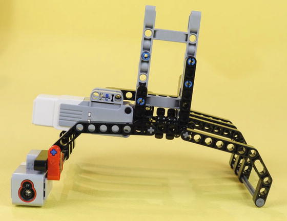
Figure 19-27. The completed Figurine Jaw Cage, seen from the bottom
Second Section: Neck/Infrared Sensor Frame Assembly with Caster Wheel
Figures 19-28 through 19-50 demonstrate the construction of the rear caster wheel and the Neck/Infrared Sensor Frame assembly . This caster wheel is similar to the one used by our ExploroBot in Chapter 3. The idea of a caster is that it can swivel easily and will not alter the robot’s course as determined by the two main drive wheels.
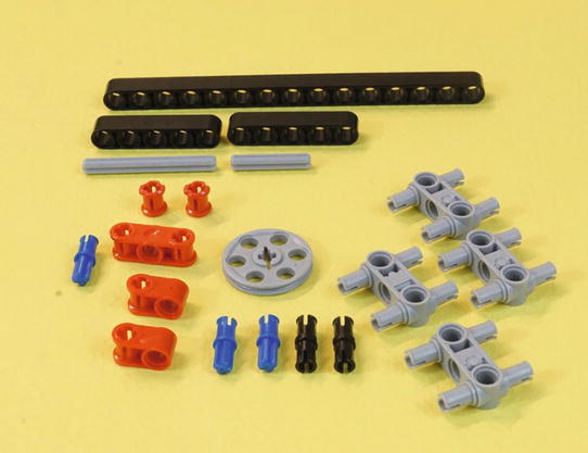
Figure 19-28. These are all of the parts you need for this section. You’ll have the caster wheel and an important part of the frame. The axles are five-hole and three-hole lengths.
Engineering: Rear-Wheel Designs and Their Constraints
There are other ways to make a rear-wheel. You can get a hard plastic ball, say, a little larger than a ping pong ball, and simply set it underneath a few frame pieces so it won’t roll out. That works surprisingly well, since a ball will turn any number of degrees you want, right away. It effectively has a 360-degree “swivel.” Another approach is to use the “peg-leg” as the SnapShotBot uses in Chapter 11. Peg-legs are particularly easy to design but they do require a rather smooth floor.
A caster will work on smooth floors and will be okay on a slightly irregular surface as long as the bumps aren’t too big. If you’re running on carpet, you’ll need tank treads (see the GrabberBot in Chapter 15) or a ball of two or three inches in diameter.
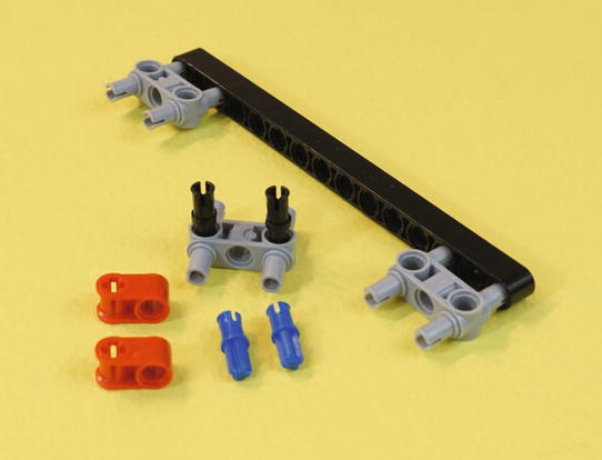
Figure 19-29. Start with these parts. Note the partial assembly of these three double connectors.
Press all of the parts all the way in. Flip the 15-hole beam over, to the orientation seen in Figure 19-30. Press the center gray double connector in place, in holes 7 and 9. That will center it on the 15-hole beam, attached by the two black pins. Then insert the blue half-axles into the red pieces. Place those on top of the center gray connector as shown. Press everything together, then set this piece aside for a moment as you build the caster wheel.
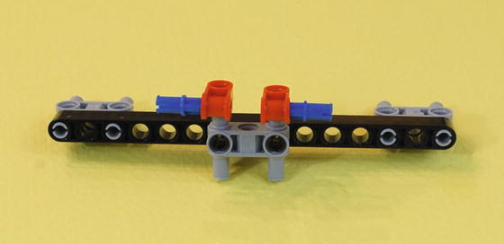
Figure 19-30. Insert the blue half-axles into the red pieces, place them on top of the gray double connector , and press them all together. A completed view is shown in Figure 19-34.
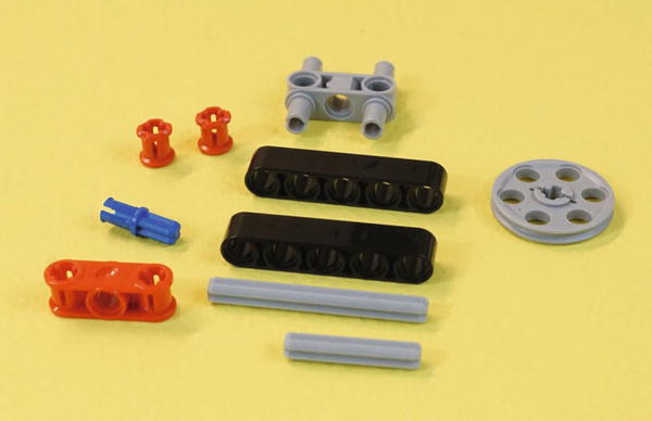
Figure 19-31. These are the pieces remaining from Figure 19-28. Now to make the caster wheel.
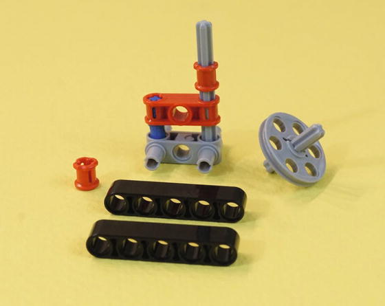
Figure 19-32. The five-hole axle stacks into the gray double connector , with the red part, blue half-axle, and red collar. The short three-hole axle goes into the wheel. Press the red parts all of the way down onto the five-hole axle.
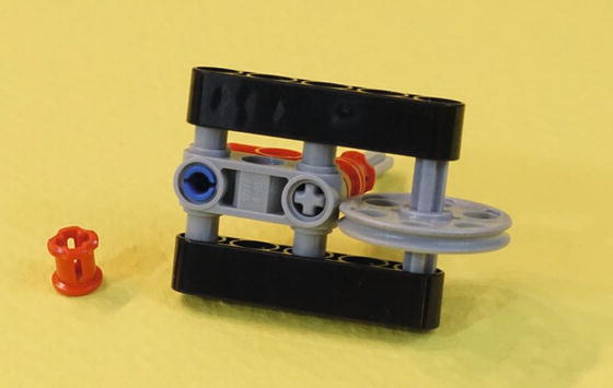
Figure 19-33. The two five-hole beams make a little wheel frame. Press them together so the caster wheel assembly looks like the foreground of Figure 19-34.
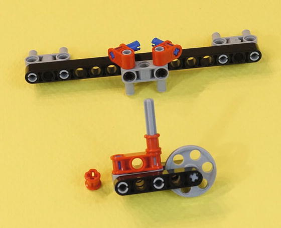
Figure 19-34. All of the parts are pressed together. The axle will go in the center of the middle gray connector .
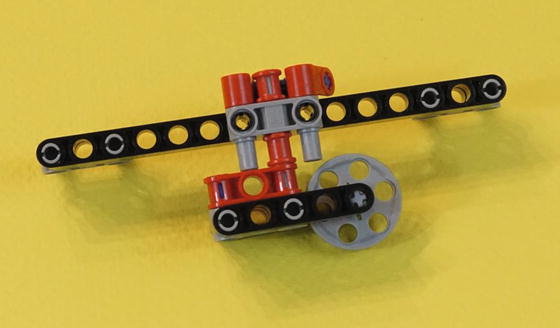
Figure 19-35. The caster wheel is in place, held in by that remaining red collar. It will swivel freely as the robot makes its turns.
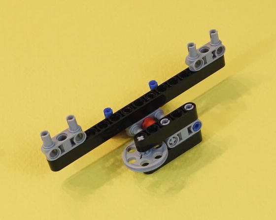
Figure 19-36. Another view of the completed caster frame assembly. Set it aside until Figure 19-47, so you can complete the rest of the neck assembly.
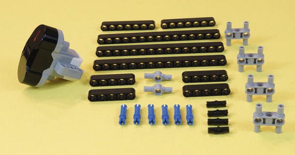
Figure 19-37. Gather all of these parts for the remainder of the Neck/Infrared Sensor assembly
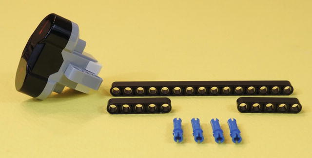
Figure 19-38. From the parts in Figure 19-37, select this 15-hole beam, two five-hole beams, four long blue connectors and the Infrared Sensor.
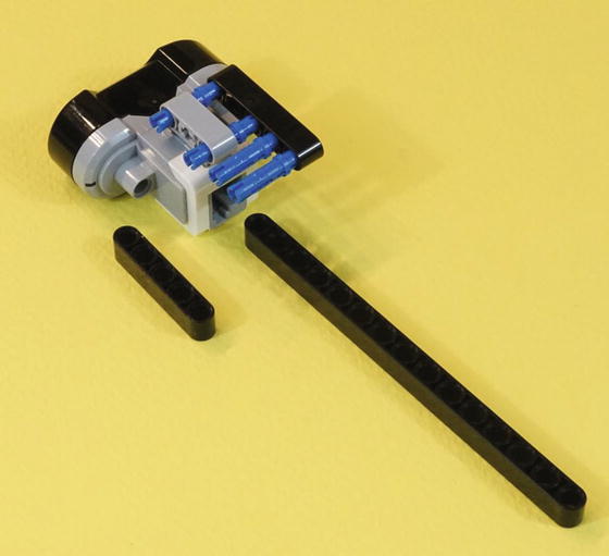
Figure 19-39. Begin the assembly of the head. These four connectors will fasten the two five-hole beams to the 15-hole beam.
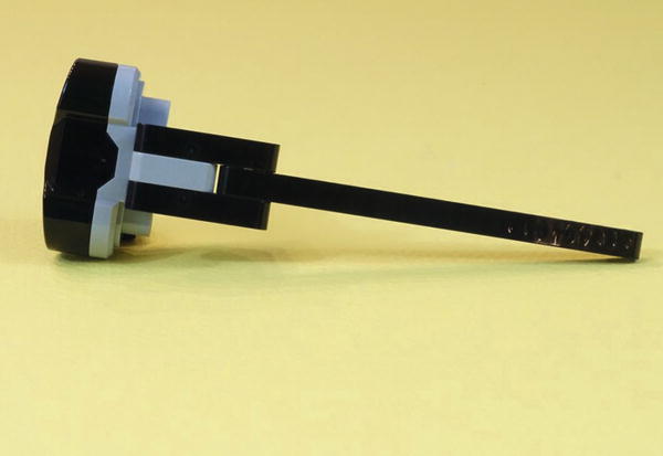
Figure 19-40. Push the connectors together, and your Infrared Sensor neck and head are ready for the next step
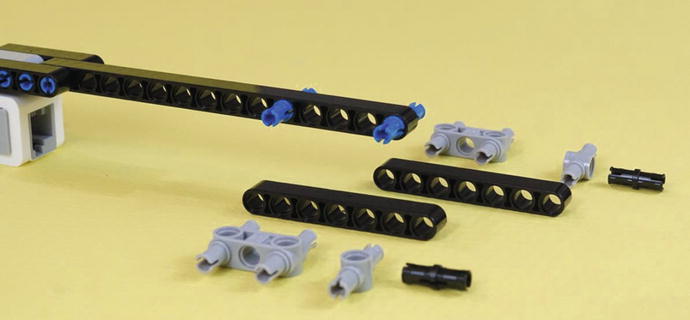
Figure 19-41. From the remaining parts in Figure 19-37, take two long blue connectors, two seven-hole beams, and the other parts shown here. Insert the long blue connectors into the 15-hole beam as shown.
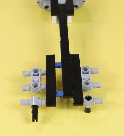
Figure 19-42. Assembling the Infrared Sensor neck. Press the pieces together, which will then look like Figure 19-43.
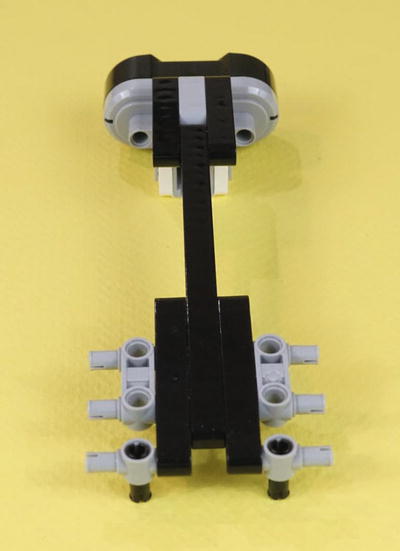
Figure 19-43. The assembled Infrared Sensor neck
Let’s take a look at all of the parts so far. In the middle of Figure 19-44, we see the completed Infrared Sensor neck assembly. Behind that is the caster wheel assembly. In the foreground are the remaining parts from Figure 18-37. They are the two 15-hole beams, two five-hole beams, two gray double connectors, and two black pins. As they are assembled, they too will be symmetrical, as are most parts in this bot.
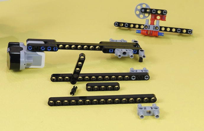
Figure 19-44. The completed neck and caster wheel, ready to go. In the foreground, you’ll use the remaining parts from Figure 19-37. Begin to assemble them as shown, so you get two long support assemblies. The loose pieces in the foreground will assemble to a mirror image of the piece behind them.
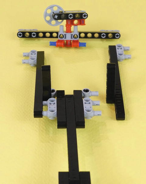
Figure 19-45. Fasten the two long support assemblies to the Infrared Sensor neck assembly. The five-hole beams point up as shown, and the two black pins at the back of the neck point down.
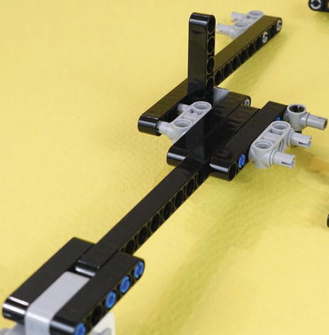
Figure 19-46. A side view of the same pieces as shown in Figure 19-45. The five-hole beam fits in between the double gray connector and the end gray connector. Press this left side all the way in.
This next step, shown in Figure 19-47, is one of those steps that “gets interesting.” No new parts coming in. Instead, we’re connecting parts that have been hanging around for a while. This is usually one of the more satisfying steps in building a bot using directions. You have all these partially built pieces with connectors sticking out. They need a place to go! And in Figure 19-47, it’s happening. Then, the completed piece is shown in Figures 19-48, 19-49, and 19-50↓three views of the completed piece, from the back, bottom, and side.
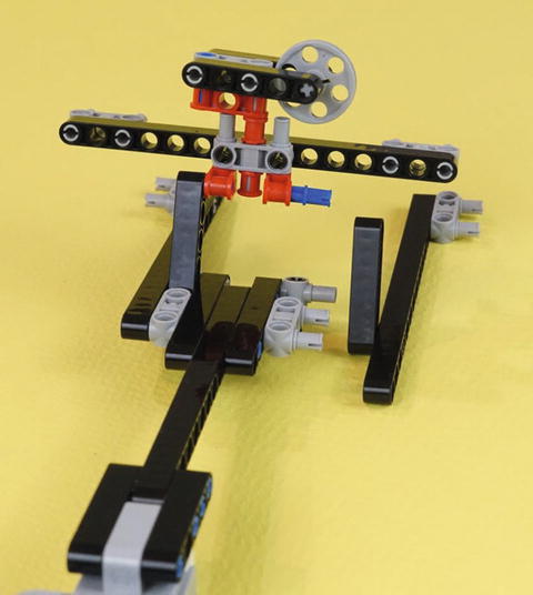
Figure 19-47. Now that caster frame piece joins in! Press the right-side long beam into the neck and caster assembly in the same manner as the other side. Figure 19-48 shows a view of the completed item from the back side.
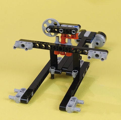
Figure 19-48. Turn it around to see the back side of the Neck/Infrared Sensor•caster wheel and frames
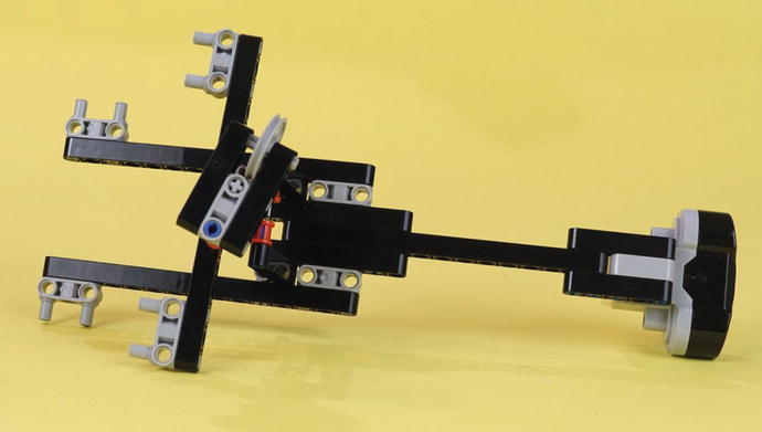
Figure 19-49. Bottom side of the Neck/Infrared Sensor caster wheel and frames
Multiple, completed views can be very useful as you build. For one thing, you might skip ahead to see what you’re building. Secondly, they’re handy if you’re ever thinking, “Hang on, how was this step supposed to work?” You can double-check your assembly steps by referring to the different views.
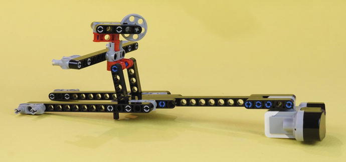
Figure 19-50. Side view of the completed Neck/Infrared Sensor frame assembly with the caster wheel
Third Section: Main Body and Motors
The PushBot is almost complete. Figures 19-51 through 19-72 demonstrate the steps needed to assemble the final bot.
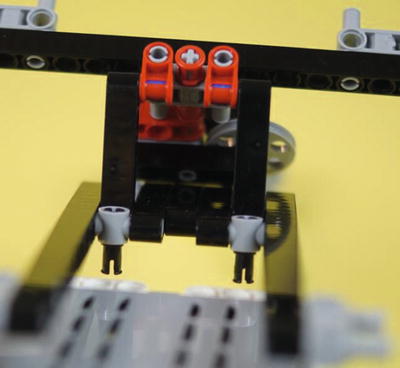
Figure 19-51. Prepare to insert the two small black connectors in the top of the Brick as shown
Start with the Neck/Infrared Sensor assembly and Brick, as shown in Figure 19-51. In this figure, the Brick’s “top” (where the USB port is located) is toward the bottom of the picture, although it’s not visible in these shots. Figures 19-51 and 19-52 are different from most of the rest in this book. They are photographed to call attention only to the connectors that are about to be attached. The rest of the image is out of focus on purpose. Most other pictures in the book are photographed with all the parts in focus. But in the case of Figures 19-51 and 19-52, it helps to highlight the specific connection without other distracting details.
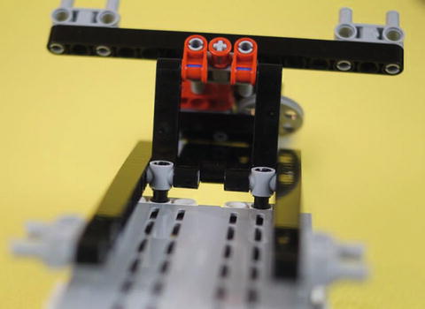
Figure 19-52. The two connectors, partially inserted into the Brick. Press them in all the way and your bot will look like Figure 19-53.
In Figure 19-53, the major parts are once again in focus and you can see how they are attached. In that figure, notice that the bottom of the Brick is toward the bottom on the picture. The bottom is the side with the A-B-C-D motor ports and the other USB port marked PC.
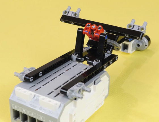
Figure 19-53. The neck assembly is attached. The “bottom” of the Brick, motor ports A-B-C-D, is toward the bottom of the picture.
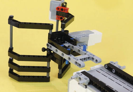
Figure 19-54. Now the Figurine Jaw Cage is about to join in. Those long blue connectors on the bottom will engage the bottom of the Brick.
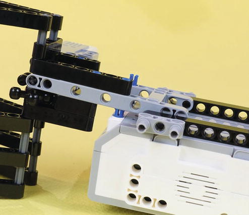
Figure 19-55. Side view of how the long blue connectors go in. Press them all the way down.
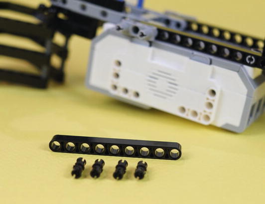
Figure 19-56. Five new parts ➤ a nine-hole beam and four short black connectors
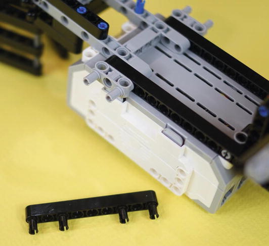
Figure 19-57. Assemble the new parts like this. They create a reinforcing beam for the Figurine Jaw Cage.
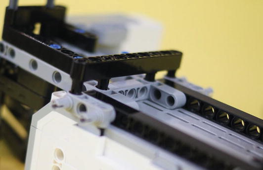
Figure 19-58. This is where the reinforcing beam goes. It helps hold the neck assembly, Figurine Jaw, and Brick all together.
Engineering: Prototypes and Parts You Don’t “Need”
Figures 19-59 and 19-60 show the mounting of a long axle that reinforces the whole structure. You don’t “need” these parts. And, if you have to change the batteries, they’re one more thing you have to push out of the way to get the old batteries out. But they do make the structure stronger.
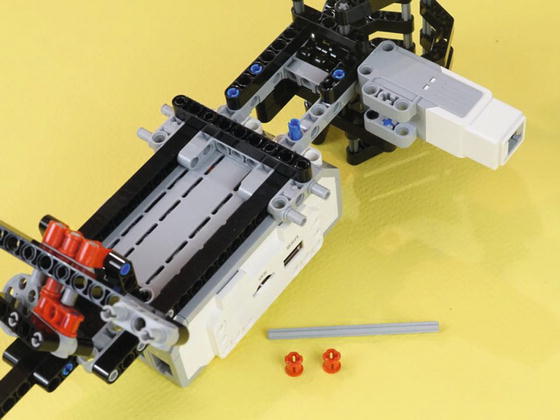
Figure 19-59. Here are the two new parts for reinforcing the frame ➤ a long axle and two collars
It’s worth taking a moment to ask how that axle got into the design. And that gets us to thinking about prototypes. When you start building, you usually want to get something running so you can test it and see if it even has a realistic chance of solving the problem. That’s what happened with this bot. When it became clear that the wheels and caster were reliable, I sat down to design a jaw. That took quite a few iterations, and each one became more compact and more reliable than the one before. Then I added as many long and short pins as possible, since strength is very important for a motorized part such as the jaw. So I would not call those dense pins “parts I don’t need.”
In the case of the reinforcing axle shown in Figure 19-60, the robot runs fine without it. There is no motorized part dependent on this for strength. It does have two advantages, though. One, it makes the robot more sturdy, particularly when I pick it up and set it on the course. Two, it has sort of an esthetic value↓“it’s there because it can be there.”
With that thought, we get to another engineering concept↓“gold plating!” Once you’ve finished something and it does the job it needs to do, there’s a tendency to sit around admiring it and thinking “What else can I add to my robot?” Experienced engineering managers are used to seeing this and sometimes step in to say, “Hey team, this design needs to be frozen. No more work on it. We go with what we’ve got.”
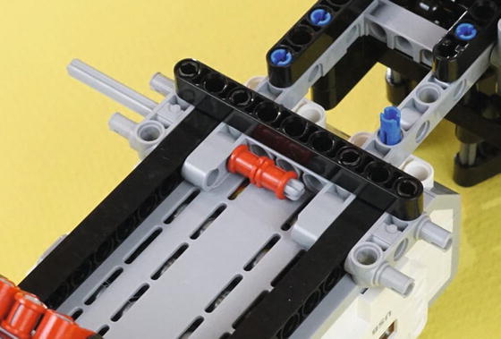
Figure 19-60. Insert the axle, engage the two red collars, and push the axle the rest of the way in. Then press the collars as far apart as possible, for maximum strength.
The neck assembly and Figurine Jaw are mated to the Brick. Now we need to build a couple of large motors with wheels and mounts. They are mirror images, as often seen on LEGO driving bases.
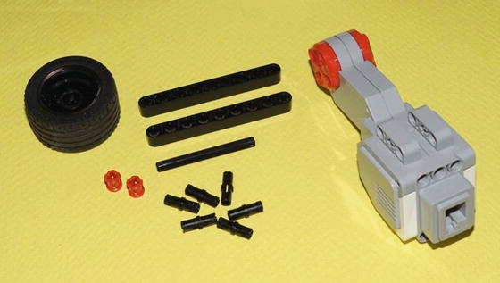
Figure 19-61. All the parts to make one large motor drive wheel assembly. You’ll make two of these, as mirror images. The axle is a six-hole length.
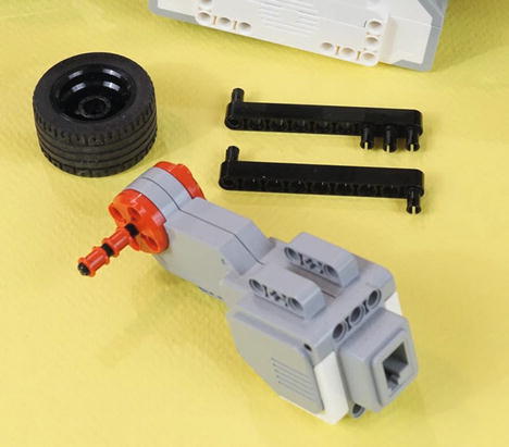
Figure 19-62. The axle goes into the large motor, along with two collars. Press the tire onto the axle. Put the six pins into the two nine-hole beams.
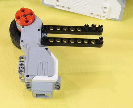
Figure 19-63. Place the beams on the large motor as shown. Again, you’ll make two of these. The other one will be a mirror image. Both mirror-image large motors are shown in Figure 19-64.
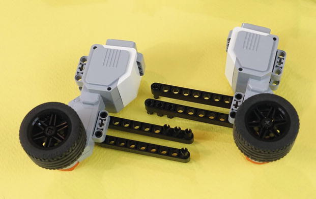
Figure 19-64. Both of the motors with frame pieces, ready to be attached to the Brick
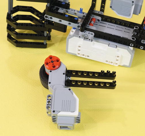
Figure 19-65. Lift this motor up and press it into the Brick and frame pieces, as shown in Figure 19-66
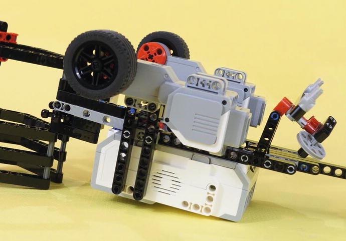
Figure 19-66. A lot of connecting happens here. The four black pins on the motor’s nine-hole beams go into the Brick itself. At the same time, that double gray connector sticking out from the frame under the bot connects with each beam.
Both large motors should now be attached to the bot, with all pins pushed fully in. And now, one more shallow-focus picture to call attention to one specific component. The last thing we need to do is hook up the beam holding the caster wheel to the two large motors. In Figure 19-67, we see the double gray connector standing out against a soft background. It needs to go into that motor just behind it. This is shown in the normal, fully-focused, picture in Figure 19-68.
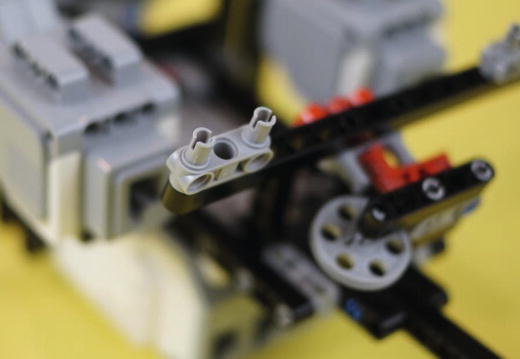
Figure 19-67. This double gray connector will go into the motor closest to it. Same with the one on the other side.
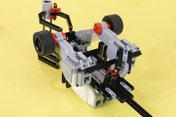
Figure 19-68. The two double gray connectors on the long beam are ready to engage the large motors
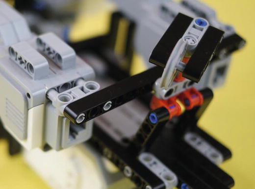
Figure 19-69. This double gray connector engages the large motor next to it. Do the same with the one on the other side. Press the connectors all the way in.
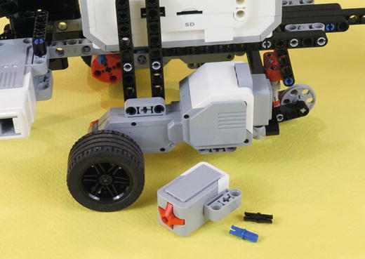
Figure 19-70. The last parts! Gather up the Touch Sensor , a short blue axle-pin, and a black pin
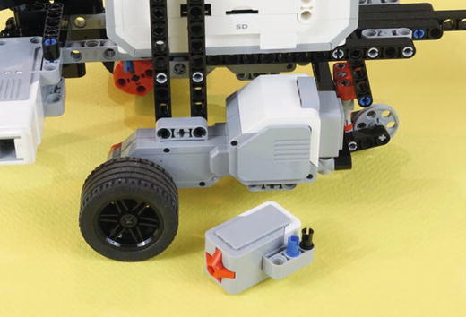
Figure 19-71. Insert the short blue axle-pin and the black connector pin into the Touch Sensor
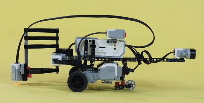
Figure 19-72. Find a convenient spot on the Brick to mount the Touch Sensor . Then wire the three motors and the three sensors. All six wires from the EV3 retail kit are used in this design.
Wiring the PushBot will use every wire found in the retail kit. The Medium Motor goes on port A. The Large Motors go on ports B and C. Wire the Touch Sensor to port 1, the Color Sensor to port 2, and the Infrared Sensor to port 4. Figure 19-73 shows this setup.
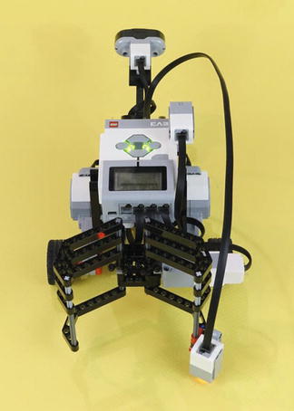
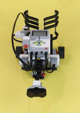
Figure 19-73. On the left, motor ports A, B, and C are used. On the right, sensor ports 1, 2, and 4 are used
In Chapter 20, I show you how I intend to program this PushBot to complete its tasks. When you’ve wired up this PushBot (or your own version), continue reading. You’re almost ready to send the bot into the burial chamber . . .