
Before you begin building the ExploroBot, take a look at Figure 3-1. Remember, this is just one possible version of the ExploroBot. Some of you might choose to design and build your own version without going through this chapter, but for those who want to build the one pictured, I have a few suggestions.
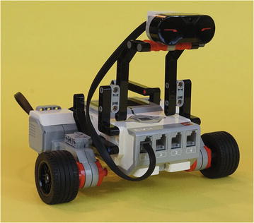
Figure 3-1. Evan’s version of the ExploroBot
Never Be Afraid to Experiment
I’ve included actual pictures of the construction of the ExploroBot . I’ve tried to provide enough detail in each figure for you to understand which parts are used and where those parts are placed. If you find that what you’re holding in your hands doesn’t quite look like the picture, do the following:
Take a deep breath.
Remember this is supposed to be fun.
Go back to the previous step and confirm you’ve made it that far.
Look at the current step and examine the figure’s details for clues to where components should be placed. Counting holes to determine where two or more parts connect is useful. So is skipping ahead a few figures to try and see the parts from another angle.
When in doubt, take your best guess and move forward.
If you do hit a roadblock and just can’t figure out how to proceed, try taking a look at the next few steps. Often, another figure will show the ExploroBot from a different angle and you’ll see the solution. Enjoy the building process and realize that if your final bot doesn’t look exactly like the one in this chapter, that’s okay. Remember: getting the bot to work and solving the challenge is your main goal.
Note
If you modify or create your own version of the ExploroBot (or any other bot in this book), please take a picture and e-mail it to me. I would enjoy seeing your final bot in action. I’ve included my e-mail address in the Introduction.
And now, on to the construction of the ExploroBot!
Step by Step
I’m going to break the ExploroBot into four sections. The first section is the Infrared Sensor and the “neck” used to support it. The second section explains the body, including the two large motors and two wheels. The third section explains the rear-wheel framework and reinforcing strut. You’ll completely assemble the ExploroBot in the fourth section using the head/neck, body/motors, frame/rear-wheel, and strut subcomponents. For many sections, I simply jump from figure to figure. I make comments where I feel an area might be tricky or where I feel you need to be made aware of a special assembly instruction. Pay particular attention to those figures showing the individual parts lying unassembled. These will help you determine what parts to locate for the assembly figures that follow. Here we go …
First Section: Infrared Sensor and Neck
Starting with Figure 3-2 and continuing through Figure 3-6, you’ll be assembling the ExploroBot’s head and neck . Take a look at Figures 3-2 and 3-3. They show the parts you’ll be using in this section.
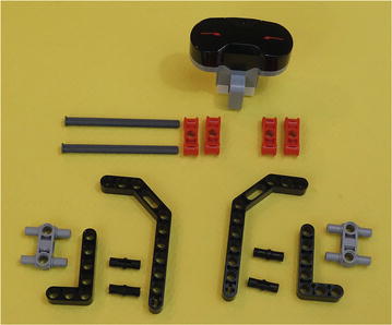
Figure 3-2. These are all the parts you’ll need for the ExploroBot’s head and neck

Figure 3-3. Beginning assembly of the parts for the left and right sides of the neck that will hold the ExploroBot’s head
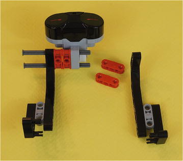
Figure 3-4. Partial assembly of the head and neck, with long axles pushed in part way

Figure 3-5. Further assembly of the sides of the neck and head, with long axles driven all the way through the left side
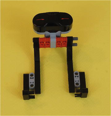
Figure 3-6. The fully assembled ExploroBot head and neck—set this aside for now
It’s time for a quick check here. Take a look at your ExploroBot head and neck. Does it look like the one shown in Figure 3-6? If not, try to identify where the difference is and go back to the figures showing the assembly. If the difference is obvious, spend a few minutes looking at the parts and you’ll find the mistake. When working with such small parts, it’s not uncommon to connect a part in reverse or upside down. I do it all the time.
When you’re satisfied with the ExploroBot head and neck assembly, set it aside for now. We’ll come back to it after you’ve completed the main body, rear-wheel, and support strut sections.
Second Section: Bot Body and Motors
In this section, you’re going to build the ExploroBot’s main body and its two motor/wheel combinations. Take a quick look at Figures 3-7, 3-8, and Figure 3-9. These three figures show all of the parts you’ll be using in this section.
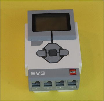
Figure 3-7. The body will consist of the Intelligent Brick, with motors and assemblies to be fastened to it
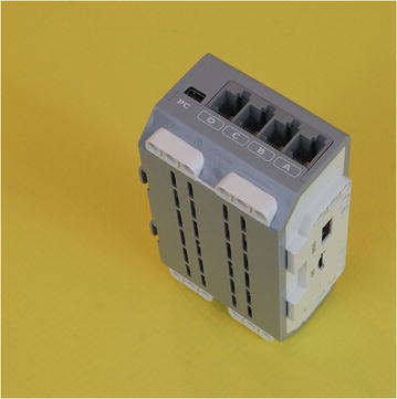
Figure 3-8. Side view of the Intelligent Brick

Figure 3-9. All the components for the left and right side motor/wheel combinations
In Figure 3-9, you can determine the length of the gray axle rod by comparing it to the length of the beam, up to the bend. In the figure, there are two full-thickness round axle bushings (red) and two half-thickness round axle bushings (yellow). These two half-thickness bushings are shown standing up so you can see the thin groove. They are used as spacers to keep the rubber wheels from touching the orange motor hub face. Figure 3-10 shows the first steps of assembly.
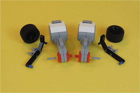
Figure 3-10. Partial assembly of the left and right motor/wheel combinations
What I call a “round axle bushing” is also called by its official LEGO name: Part# 3713 Technic Bush. Why do I tell you this? Because I want you to be aware that LEGO gives a unique part number to every component it sells. (Also, because this is where I tell you that I usually avoid using the official part numbers.) If you’re unable to determine the identity of a component from a figure, take a look at the next figure or two. You’ll most likely be able to figure out what the component is by seeing it from a different angle or by seeing it where it’s placed.
Let’s build the base.
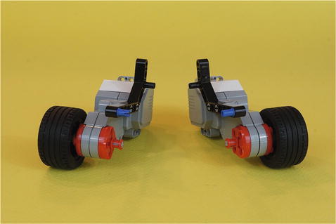
Figure 3-11. The completed motor/wheel combinations. The long angle brackets have been positioned on the inside edge of the large motors.
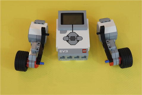
Figure 3-12. The Intelligent Brick and the motor/wheel combinations, before putting them together
Okay, it’s time again to check your work. Compare your ExploroBot body with the one shown in Figure 3-13. You can use Figure 3-13 to compare things such as the location of the black connectors in the angle beams. This helps you confirm that you have the motor/wheel combinations located properly.


Figure 3-13. So far, this robot is the same on both sides—it’s symmetrical
Again, the key here is to look for any major differences between your ExploroBot’s body and the one shown in Figure 3-13. If you find any differences, just go back and examine the figures carefully to determine where the mistake appears to have been made. If necessary, take the assembly apart and start over. You have plenty of time and you’re having fun, right?
Are you happy with the ExploroBot’s body? Congratulations! You’re half done with the ExploroBot. We’re going to move on to the third section, which gives us a rear-wheel assembly. Just take your time on this section and enjoy the building process. Remember my advice—if you get stuck, just take a deep breath and remind yourself that this is fun. You can’t make a mistake because you can always start over. No harm done!
Now let’s finish the ExploroBot’s rear-wheel section and then get this bot assembled…
Third Section: Rear-Wheel Assembly and Reinforcement Strut
There are two separate structures to build in this section. First you’re going to build a small but quite useful rear-wheel assembly. You will probably use this design on other projects since it is a fine way to make a two-wheel robot that maneuvers well. You’ll also make a base to hold the rear-wheel. This base has relatively few parts because it uses a rectangular frame piece, making it fairly strong by itself. Then you’ll add a reinforcement strut, which further strengthens the bot and supports the rear-wheel. Your bot will work without the reinforcement strut , but it does make it more solid. You can see this in the Figure 3-37 side view. Notice that the rear would sag without the strut.
Take a quick look at Figures 3-14, 3-19, and 3-23. These figures show most of the parts you’ll be using in this section, but in some later figures you’ll notice I’ve added some new parts. My best advice is to pull out the parts you need in these three figures. You’ll know when I’ve added some new parts because you’ll have used all the previous ones you set aside! And again … when in doubt, just pause and examine the figures more closely. I’ve made sure to include enough detail for you to figure out what parts are being added to the mix.

Figure 3-14. These are the parts for beginning the rear-wheel
Next, Figure 3-14 shows the parts that go in to the rear-wheel. The following figures show how to assemble the wheel.
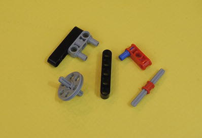
Figure 3-15. It’s not quite a rear-wheel yet, but keep going
Note
In Figure 3-16, you’ll notice that I’ve added two new parts that weren’t seen in Figure 3-14. This will happen again in later figures, so be on the lookout for it. As I mentioned, if you set out the parts that you need for each section, when I add parts like this to a figure, it will be obvious to you. “Hey, that’s not in my parts pile!”
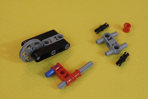
Figure 3-16. The rear-wheel is starting to come together
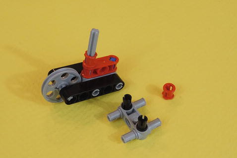
Figure 3-17. The rear-wheel is almost done…
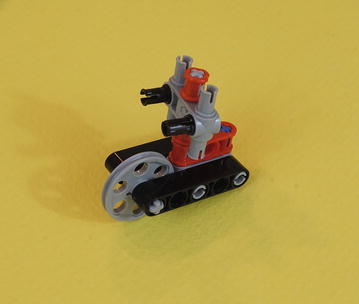
Figure 3-18. The complete rear-wheel assembly—set this aside for now
This is a useful little assembly—low friction and quick to make a turn without changing the robot’s path on its own. (You’ll see this useful fellow again in Chapter 19.)
Finally, Figure 3-19 shows the parts needed to make the rear-wheel frame. Three black connectors have already been inserted into the rectangular component.
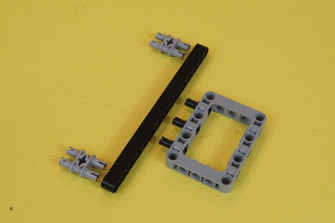
Figure 3-19. Gather these parts to build the base frame that will hold the rear-wheel

Figure 3-20. Connect the parts as shown. The gray rectangular frame is actually off-center by one hole. This will position the wheel so it ends up centered.
Congratulations! You’ve finished the rear-wheel base. Do a quick check and compare the base you assembled to the one shown in Figures 3-21 and 3-22. The rectangular frame piece is offset by one hole from being centered, which allows the rear-wheel to end up right in the middle.
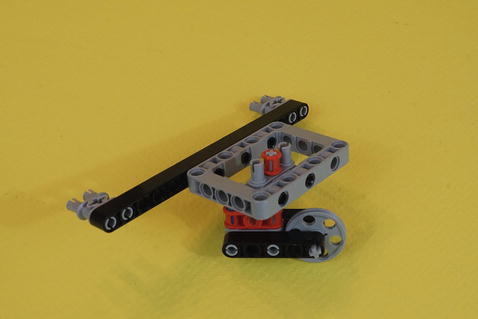
Figure 3-21. Place the wheel assembly inside the rectangular frame piece

Figure 3-22. Another view of the completed rear-wheel base assembly. Counting the beam holes on each side shows how the gray frame is off center on the black beam.
Engineering: Axles as Reinforcements: Strong and Adjustable
Now it’s time for the reinforcement strut . Here are a couple of engineering ideas that will prove useful later. The first involves the strength of axles. In Figure 3-23, there are three short axle-like parts and one longer axle. Many times you will have a choice between short black connectors and the equally short blue half-axle/half-connectors. If you look on the end of the black angle piece, you’ll see it has an axle-shaped hole. These connections are stronger than regular connectors.
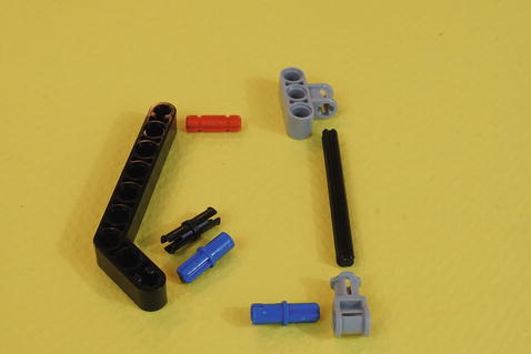
Figure 3-23. These are all of the rear-wheel reinforcement strut parts
Tip
Using Axles When designing ways to hold things together, always remember to ask, “Will some kind of axle make this stronger? Or more adjustable? Can I use some of those odd axle connectors?”
The other engineering idea is that axle connections are adjustable. Beam connections are not. This means that you can use an axle where a beam would not quite fit. This pays off if your angle is not an even 45 or 90 degrees. You can also make an axle as tight as you like by sliding it along its connectors or adding more collars.

Figure 3-24. The partially completed rear-wheel reinforcement strut

Figure 3-25. The completed rear-wheel reinforcement strut with adjustable axle length. This controls the firmness of the strut when it is on the ExploroBot.
Congratulations! With this reinforcement strut you’ve finished all of the sub-assemblies. Now it’s time to pull all of them together.
You should have the following ready to go:
Head and neck assembly
Main body with motor/wheel combinations
Rear-wheel base
Rear-wheel reinforcement strut
Place them all within reach. It’s time to finish building the ExploroBot.
Fourth Section: Put It All Together
Take the main body assembly and the rear-wheel/base and turn them upside down. You’ll see this in Figure 3-26. Connecting the rear-wheel/base and the main body should be straightforward. Before attempting it, take a thoughtful look at Figures 3-26 and 3-27. This is also a good place to mention that I’ll sometimes use “callouts” in the figures. These “callouts” are simply text in the figure itself, sometimes with lines or arrows. In this case, I use arrows to show the destination and direction of the quad-connectors hooking everything together.

Figure 3-26. Turn the main body and the rear-wheel/base upside down to connect them. The rear-wheel is pointing up in this view.
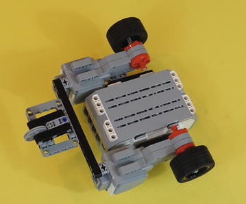
Figure 3-27. The main body and the rear-wheel/base are connected

Figure 3-28. The assembled main body and rear-wheel/base
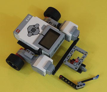
Figure 3-29. Rear-wheel reinforcement strut ready for installation between body and rear-wheel/base
Remember the tip about axles? Now you are putting the tip to work. The axle in that reinforcement strut is adjustable! This means you can slide it up or down to get the amount of stiff reinforcement you desire. That is, if you notice the rear-wheel is drooping, tighten this axle connection. Does it seem to come loose? Add more collars to the axle to make it stronger.

Figure 3-30. Rear-wheel reinforcement strut, main body, and rear-wheel/base assembly
Next, gather the head/neck assembly, as shown in Figure 3-31.
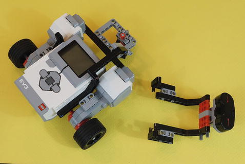
Figure 3-31. Head/neck assembly ready for mounting on main body
Finally, on the front of the main body, you’re going to connect the head/neck assembly, as shown in Figure 3-32. You’ll stretch the sides apart to get the connectors lined up with the body.
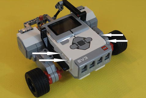
Figure 3-32. The head/neck assembly will connect to the main body here
You see the head/neck assembly connected to the main body in Figure 3-33. Take a close look and you’ll see exactly where the left and right neck components connect to the Intelligent Brick.

Figure 3-33. The head/neck assembly connected to the main body (angle view)
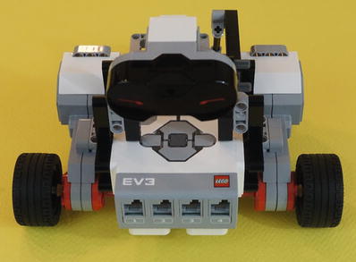
Figure 3-34. The head/neck assembly connected to the main body (front view)
Guess what? You’re done with building the ExploroBot. To complete the wiring, do the following:
Connect a short cable from the Infrared Sensor to port 1, as shown in Figure 3-35.
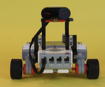
Figure 3-35. The Infrared Sensor connects to port 1
Looking at the back of the ExploroBot as shown in Figure 3-36, connect a cable from the left motor to port B.
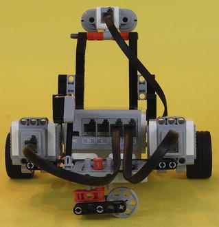
Figure 3-36. The large motors are connected to ports A and B
Connect a cable from the right motor to port A, also shown in Figure 3-36.
And that’s it. You’ve built the ExploroBot. Figure 3-37 shows the completed project from various perspectives.

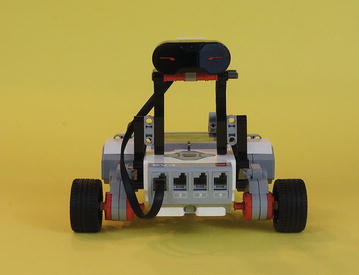
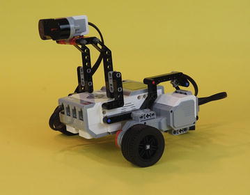
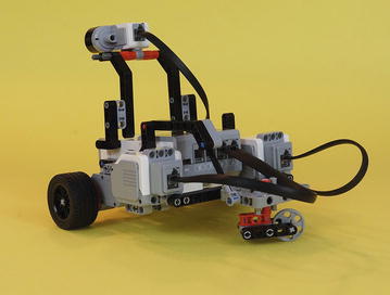
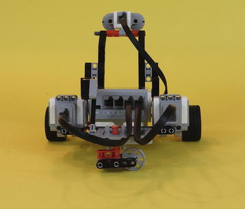

Figure 3-37. The completed ExploroBot from various angles
But you’re not done. Sorry.
Chapter 4 covers programming your ExploroBot. Without the programming to tell the bot how to behave, you have a nice paperweight and a locked tomb door.
So, on to the next chapter.