
The PushBot has a lot to do! Because of this, I want to be absolutely certain that my program works, and I’ll be testing it often. To make it easier on myself, I’m going to break down the program into three sections. The first section covers getting the bot to the proper location in front of the first figurine. The second section covers the programming blocks used to put the first three figurines into their proper locations. And the final section is devoted to pushing the last figurine up the ramp and onto the Mayan sarcophagus.
If you’ve built your own version of the PushBot, your program will most likely not match mine exactly. It really depends on how you’ve built your bot to complete the challenge.
In the next three sections, I walk you through the programming of this last bot so the team can finally enter King Ixtua’s burial chamber and see what it contains. So, without any further delay, let’s get this bot programmed and ready to go.
Getting the PushBot Into Position
In the LEGO MINDSTORMS EV3 software, click on the + tab at the upper left and then double-click on the blue Program name. Then type PushBot. Your screen should look like Figure 20-1.
Figure 20-1. The beginning of the program for the PushBot
Note
To have more workspace visible on your screen, minimize the Document Your Work area on the right by clicking the EV3 Button symbol at the far right of the top tab bar. (This symbol is shaped like a little stop sign—that is, an octagon. It resembles the buttons on your EV3 Intelligent Brick.)
Once again, I am using the Touch Sensor as a Start button for the PushBot. You can choose to use one of the Brick’s buttons, but I like the simplicity of running the program and having it wait until I press the Touch Sensor. I’ve placed the Touch Sensor in an easy-to-reach place on top of the Brick.
The first block I’ve dropped in my program is a LOOP block (see Figure 20-2). It will wait for the Touch Sensor to trigger.
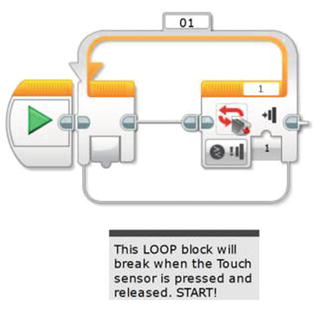
Figure 20-2. This LOOP block will break when the Touch Sensor is triggered. The sensor is on Sensor Port 1.
The first task my bot must perform is “Move from pedestal to first figurine without touching it.” I’m going to take advantage of the fact that I can place my PushBot initially on the floor and point it directly at the first figurine. After that, I have a couple of different methods available for getting the bot into position.
I know roughly the distance between the pedestal and the first figurine, so as long as I program the bot to stop before it touches the figurine, I should be safe. If you look back at Figure 17-2, you see that the estimated distance is seven feet. I have measured my PushBot and it is just about 16 inches long. Take a look at Figure 20-3. If I place my bot as shown and point it toward the first figurine, it will need to move forward 5.5 feet and then stop to avoid touching the figurine. So, for the first method, I could program a MOVE STEERING block with the correct number of rotations (or degrees) to move it 5.5 feet.

Figure 20-3. The PushBot’s initial movement will be 5.5 feet forward, based on the Infrared Sensor stopping in front of the first figurine
But I want to use the second method that relies on the Infrared Sensor. Why do I want to do this? Well, if my measurements are off by just an inch or two, I might accidentally bump one of the figurines. I’ve noticed that when the batteries get low in my bot, sometimes strange things can happen with the motors. What I’d prefer is to use the Infrared Sensor to detect the figurine and stop the bot a safe distance away. And to accomplish this, I’ll simply program my bot to move slowly toward the figurine, constantly checking to see whether it detects an obstacle (a figurine).
In Figure 20-4, you’ll see that I’ve dropped in a LOOP block that is configured to break when the Infrared Sensor is triggered. Since I haven’t tested it yet, I’ll set the Infrared Sensor to be triggered when it detects an obstacle less than 30 centimeters (12 inches) away. Remember, this might change once I test the sensitivity of the Infrared Sensor.
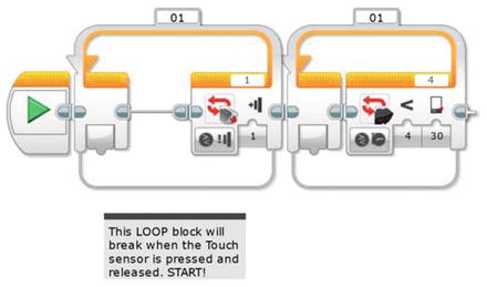
Figure 20-4. This second LOOP block will break when the Infrared Sensor is triggered. It is on Sensor Port 4
Before I perform an initial test of my PushBot, I’ll place a MOVE STEERING block inside the LOOP and tell it to spin motors B and C. I can choose to set the Duration of the motors either to Unlimited or for a specific number of degrees or rotations. I will test both methods to determine which is the safest way to approach the figurine. You can see the MOVE STEERING block in Figure 20-5, and this block is initially configured to spin for one rotation. I am doing this because I want the bot to move forward, the Infrared Sensor to test for distance, and then the bot to move forward one rotation again. This will continue until the Infrared Sensor is triggered. (I’ll also test it with the motors spinning constantly until the Infrared Sensor is triggered.)
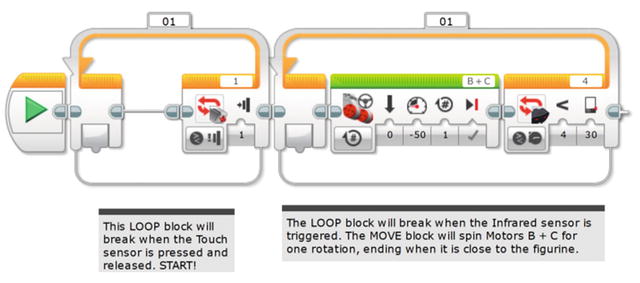
Figure 20-5. A MOVE STEERING block for the PushBot
I place a bottle of water about nine feet away from the PushBot. I make sure the cage jaws are open. I push the Touch Sensor (Start button) and off it goes. Results? When I configure the MOVE STEERING block’s Duration to Unlimited, the bot stops much nearer to the bottle than when I configure it for a duration of one rotation. I also am forced to increase the sensitivity of the Infrared Sensor to 30 centimeters or less. After testing again, I find these settings are acceptable, and the PushBot is about 3 to 5 inches from the bottle.
Now that the bottle is found, I need to orient the PushBot to push the bottle. My PushBot design requires the bot to spin around and move toward the bottle until I tell it to stop. It will then close the cage mechanism and hold the bottle as the bot pushes it forward. The bot will stop when the black pressure plate (obsidian rock) triggers the Color Sensor. Let’s take all of this one step at a time.
When the PushBot reaches the bottle, I need it to turn 180 degrees so the cage is facing the bottle. How do I do this? Simple. I first back the bot up to give it room to turn—one rotation of motors B and C should do it. I use a MOVE STEERING block to do this, as shown in Figure 20-6.
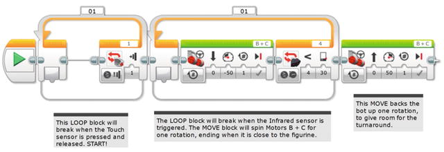
Figure 20-6. The PushBot will first back up about five inches
Next, I will turn only large motor B so the bot turns 90 degrees to the left. I will follow this with a LARGE MOTOR block that turns only large motor C so the bot turns 90 degrees to the right. At this point, the PushBot will be facing the reverse direction. This is illustrated in Figure 20-7.
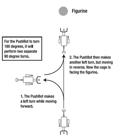
Figure 20-7. The PushBot can turn 180 degrees by a pair of LARGE MOTOR blocks
I used the method described in Chapter 4 for obtaining the correct number of degrees for large motors B and C to turn. For my PushBot, the right turn (motor B) made in Figure 20-7 requires -600 degrees. For the left turn (motor C), the motor is also configured for 600 degrees (the negative sign simply tells me to configure motor B for 600 degrees but to also change the spin direction). You cannot use a negative number as a duration, so you must enter the same value (600) but select the opposite spin direction. Figure 20-8 shows the LARGE MOTOR block for the right turn.

Figure 20-8. This LARGE MOTOR block makes the PushBot perform a right turn
I follow this with another LARGE MOTOR block for the left turn in Figure 20-9.
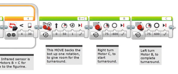
Figure 20-9. And this LARGE MOTOR block makes the PushBot turn left
I save and download the program to my PushBot for testing. And after testing, it is lined up properly with the bottle.
Now, let’s pause here for just a minute and look at where my PushBot is located. Currently, the bot has spun around and is facing the first figurine with the cage in the opened position. What happens next? Let me break it down in a small list:
Approach figurine 1.
Close the cage around figurine 1.
Push figurine 1 forward onto the pressure plate and stop.
Open the cage and reverse to the starting position.
Turn right, move forward a short distance, and then turn left.
PushBot is now in front of figurine 2.
Do you see the pattern? It will do the exact same steps for figurine 2 and then end up facing figurine 3. It will perform the steps for figurine 3, with the only difference being that after it opens the cage (Step 4) and reverses direction, it will need to be directed to the figurine near the ramp.
Because of these repeated steps, I’m going to use a LOOP block that will allow me to perform these steps three times, once for each of the first three figurines.
Positioning Three Figurines
Before my bot locates and begins pushing the final figurine up the ramp, I’ll need it to be stopped in front of figurine 3. Knowing this information will help me determine what I should place inside the LOOP block I’m going to add for the actions needed to push figurines 1, 2, and 3 into position.
But first, I’ll drop in the LOOP block (see Figure 20-10) and configure it to execute any blocks placed inside it one time. (I’ll later change this to three times after testing so it will perform the same actions for three bottles.)

Figure 20-10. The LOOP block for positioning the first three figurines. For testing, set the LOOP counter to 1. For running it on the real course, set the counter to 3, as shown.
Now, the first thing I need the PushBot to do is move slowly toward the figurine and stop when the Infrared remote detects my signal. I’ll use another LOOP block and configure it to break when the Infrared remote is triggered (see Figure 20-11).

Figure 20-11. This inner LOOP block will break when the Infrared Remote signal triggers the Infrared Sensor
I’ll add a MOVE STEERING block that will slowly move the bot toward the bottle. Figure 20-12 shows that I’ve configured it to spin large motors B and C for a quarter rotation (0.25).
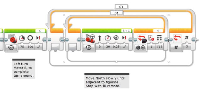
Figure 20-12. The MOVE STEERING block will spin motors B and C in quarter rotations
Now it’s time to download the program and test it. I took the default Infrared Sensor setting, which is a value of 1. That corresponds to the upper-left button on the Infrared remote.
The bot did a perfect turn and approached the bottle slowly until the Infrared remote button-press exited the loop. Now I want the cage to close and hold the bottle. This is done with a MEDIUM MOTOR block, as shown in Figure 20-13.

Figure 20-13. The MEDIUM MOTOR block closes the cage. Using time instead of degrees means the motor won’t jam, even if it cannot complete the Degree move as commanded.
I configured the MEDIUM MOTOR block to spin motor A –65 degrees. In Figure 20-13, I originally entered a value of 65 for the number of Degrees and I also configured medium motor A to spin in reverse (to take into account the negative value of the rotation). This was the proper number of degrees required to move the cage from an open position to the closed position. I obtain this value using the View option on the Brick; refer to Chapter 4 for a review on how to obtain this reading.
Yet later, I ended up with the programming shown in Figure 20-13. That is, a negative speed of 30 for a time duration of 0.25 seconds. See below for an explanation of why I made this change.
After the cage closes, I’ve added another Medium Motor block that turns off the power to motor A (see Figure 20-14). This saves battery power.
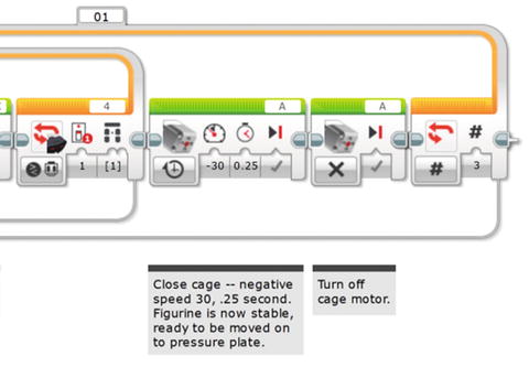
Figure 20-14. This second MEDIUM MOTOR block turns off Medium Motor A, saving battery power
Now that the cage is closed, I need the bot to slowly begin pushing the figurine (or in our tests, a bottle) until it detects the black obsidian rock floor. For testing, I’ve taped a black square of paper to the floor behind the bottle. I’ll use a LOOP block that will break when the Color Sensor is triggered (see Figure 20-15). As I have done before, I test the Color Sensor on the black paper to obtain the correct setting (following the instructions in Chapter 4 to use the View option on the Brick).

Figure 20-15. The LOOP block will break when the Color Sensor is triggered
My black paper gives me a value of 5; my floor gives me a value of 89. I will set the Color Sensor to trigger if the value drops below 20. Your values will differ, so testing is absolutely required.
I need to drop in a MOVE STEERING block to perform the pushing action (see Figure 20-16). I’ll have it push forward 2.75 inches at a time (half a rotation). And, I’ll add a half second delay to make sure the Color Sensor is able to detect the black paper.
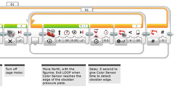
Figure 20-16. The MOVE STEERING block pushes the figurine forward in quarter rotations. The WAIT block makes sure the Color Sensor has time to “see” the obsidian pressure plate (that is, the black paper)
Note
Observe that Large Motors B and C are frequently changing spin direction. In some instances you might think your robot will move forward, but it moves backward. When I had the PushBot spin around 180 degrees, everything changed! Now when I want Large Motors B and C to spin forward, I have to configure their directions the other way. It can get confusing, but that’s why we test.
Now it’s time to download and test. If everything works as planned, my bot should approach the bottle, stop when the bottle is detected, back up a bit and spin around, approach the bottle until I tell it to stop, close the cage, and then push the bottle forward until the Color Sensor is triggered.
Does it work? Not perfectly. That’s the great thing—the essential thing—about testing frequently. I do not want to reach the end of my program only to find that I made a mistake very early! I originally find a problem with the cage—it jams and interferes with the rest of the program running. This problem is easy to fix. Medium Motor A was programmed to spin 65 degrees, but sometimes it doesn’t spin all the way closed. The motor stalls and the program doesn’t continue until motor A finishes its movement and closes the cage completely. My fix is to simply have motor A spin for 0.25 second. I’ll leave in the MEDIUM MOTOR block that stops motor A, just in case I later decide to switch back to closing it a specified number of degrees or rotations. Other than that, the PushBot works well.
It pushes the bottle onto the black paper (pressure plate) and stops. But it is only on the edge of the paper. So I’ll add another MOVE STEERING block after the LOOP to advance the figurine past the edge, onto the center. That one rotation gives me 5.5 inches. Now I just need to get it to open the cage, back up a reasonable distance, and perform a couple of movements to put it in front of figurine 2.
First, I’ll make that one-turn advance with a Move Steering and then open the cage with a MEDIUM MOTOR block (see Figure 20-17).
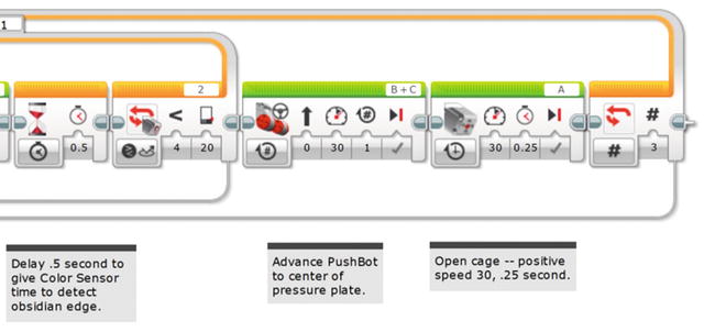
Figure 20-17. The first MOVE STEERING block centers the figurine, and the second MEDIUM MOTOR opens the cage
Next, I’ll get the PushBot to reverse direction a reasonable distance. Referring back to Figure 17-2, I think a safe distance for the bot to pull back would be about three feet. I’ll test it and tweak that value if I find the bot isn’t pulling back far enough. Figure 20-18 shows the back-up-South MOVE STEERING block I’ve added. (To configure the distance, I’ve converted 3 feet to 36 inches. I divide that by 5.5 inches—the circumference of the tires—and I get a value of approximately 6.5 rotations.)
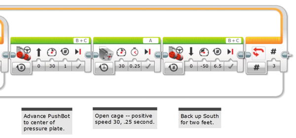
Figure 20-18. This MOVE STEERING block will get the PushBot to move away from the figurine, in the southerly direction
The last few items I need to take care of will get the PushBot in front of the next figurine. The bot needs to turn right, move forward a small distance (about two feet), and then turn left. This will position it facing the next figurine.
Then let’s make the bot perform a right turn (see Figure 20-19).

Figure 20-19. This LARGE MOTOR block turns the PushBot right, facing West
Next, Figure 20-20 shows the MOVE STEERING block needed to move the PushBot forward two feet in a westerly direction. Keep in mind that this is one of those configurations that might need to be changed; you won’t know until you test your bot with three figurines properly placed.

Figure 20-20. This MOVE STEERING block sends the PushBot forward, heading West approximately two feet
And, finally, I need the bot to spin to the left (see Figure 20-21).

Figure 20-21. This LARGE MOTOR block turns the PushBot left, facing North once again
Time to test; let me describe my testing environment. I place three water bottles four feet from a wall in my living room. The water bottles are two feet apart as well. I then fasten three squares of black paper about four inches behind each bottle (the paper is taped down so it can’t be pushed along with the bottle). I then place my PushBot about nine feet away from the first bottle, pointed directly at the bottle with the Infrared Sensor. The cage is fully open. And here’s what happens.
I have success on the first figurine, but overshoot the second figurine by about six inches. I fix this by reducing the number of durations large motors B and C spin (in Figure 20-20) from my earlier value of 6 to 4.7, as is shown in the figure. I also have a problem with the cage closing properly but opening too wide, and the arms rub the tires. I reduce the time for the cage to open from 1 second to 0.25 seconds (a quarter of a second). On the second test, I have perfect success—all three figurines are located and pushed to their proper locations without tipping over.
At this point, I’d like to remind you that your settings will probably be different. Motors and sensors all have varying sensitivity, so testing is an absolute requirement at this point. Don’t stress about this part of building robots; this is how you improve your skills and gain insight into the way robots work in different environments.
Figure 20-22 shows the approximate location of the PushBot at this point. I’ve got to get it moving so it can push the fourth figurine up the ramp and onto the sarcophagus.
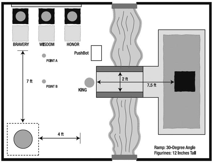
Figure 20-22. The PushBot should be located above the center of this diagram as shown
The Final Figurine
Now to what I consider the easy part. Okay, maybe not easy, but definitely easier than trying to push three figurines onto pressure plates. I have some rough distances to work with from Figure 20-22, so I’ll use these measurements, along with the Infrared remote, to position the PushBot for its final task.
First, I have to reorient the bot. Since it is pointing away from the fourth figurine, I first have the bot spin to the right and then move to point A in Figure 20-22. The cage will be pointing away from the sarcophagus when it reaches point A. I’ll drop a MEDIUM MOTOR block in for the turn to the right, facing East (see Figure 20-23).
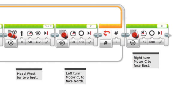
Figure 20-23. This MEDIUM MOTOR block will spin the bot to the right in a clockwise direction
Next I’ll add another MOVE STEERING block that will take the bot to point A—approximately four feet (see Figure 20-24).

Figure 20-24. This MOVE STEERING block moves the bot to point A
My bot moves back nine rotations (approximately four feet) and stops. It’s now at point A and I’m ready to get it to point B. It’s important for me to have the bot centered with the figurine and the ramp. To do this, I’ll perform plenty of tests using the Infrared Remote to get it to stop and turn at precisely the right point where I want it.
In goes another MEDIUM MOTOR block (see Figure 20-25) to get the bot to turn right (the bot’s cage will be facing away from the first three figurines).
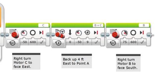
Figure 20-25. This MEDIUM MOTOR block turns the PushBot toward point B, heading South
Now I want the bot to slowly move down to point B. I say slowly because I’m going to watch it and trigger the Infrared remote to stop the bot when it reaches the center point. Again, this will take some practice to determine exactly where the bot should be when I yell “Stop!” And when I yell, I will also press that upper-left button on the Infrared Remote. The LOOP block, shown in Figure 20-26, will break when the Infrared remote is triggered.
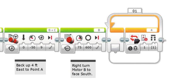
Figure 20-26. This LOOP block will break when the Infrared Remote is triggered
In Figure 20-27, I add the MOVE STEERING block that will slowly spin motors B and C. Depending on how fast and accurately I think I can push the button on the remote, I could also add a WAIT block configured for one or two seconds to give me time to watch as it approaches point B. In this case, I’m simply relying on the MOVE STEERING block with its fairly small 0.25 rotation to allow enough time to correctly trigger the turn toward the king figurine. Your own tests may show that the WAIT block would be a good thing to have.

Figure 20-27. The MOVE STEERING block is added to get the bot to point B. A WAIT block could be added after the MOVE STEERING block to gain better control.
Once the PushBot reaches point B, it needs to make a left turn (cage facing the king figurine). I add a LARGE MOTOR block for this left turn (see Figure 20-28).
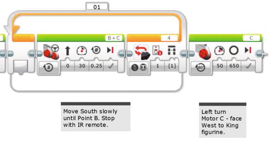
Figure 20-28. This LARGE MOTOR block turns the bot to the left with the cage facing the figurine
And now I need the bot to move (slowly) toward the fourth figurine. Once again, I’ll use the Infrared remote to tell the bot when to stop and close the cage. I add a LOOP that is configured to break when the Infrared Remote signal is received (see Figure 20-29).
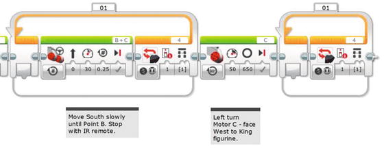
Figure 20-29. This LOOP block will break when the Infrared Remote triggers the Infrared Sensor
A MOVE STEERING block is added inside the LOOP block to move the bot toward the figurine in quarter rotations (see Figure 20-30).

Figure 20-30. This MOVE STEERING block moves the bot toward the final figurine
When the Infrared Sensor is triggered by the remote, a MEDIUM MOTOR block will close the cage on the final figurine (see Figure 20-31).
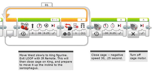
Figure 20-31. This MEDIUM MOTOR block closes the cage on the final figurine. Then that motor is turned off.
I add a final LOOP that will break when the Color Sensor is triggered by the black pressure plate on top of the sarcophagus (see Figure 20-32).
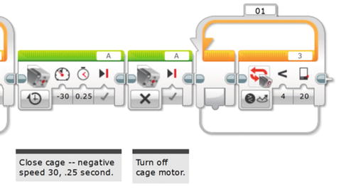
Figure 20-32. This final LOOP block breaks when the Color Sensor is triggered
This last MOVE STEERING block will spin motors B and C in half rotations until the Color Sensor is triggered and the bot stops (see Figure 20-33).
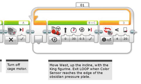
Figure 20-33. This MOVE STEERING block stops spinning when the Color Sensor is triggered
When the PushBot reaches the edge of the black pressure plate, the Color Sensor triggers the bot to stop moving. Then we need that last little push to get it to the center of the plate. The final MOVE STEERING block pushes it one more rotation, as shown in Figure 20-34, and winds up at the STOP command.
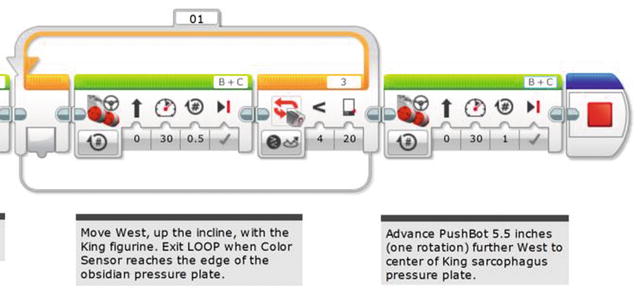
Figure 20-34. The MOVE STEERING block in the LOOP stops spinning when the Color Sensor triggers. The final MOVE STEERING block gets it to the center of the sarcophagus pressure plate.
At this point, the final figurine should be resting on top of the sarcophagus, in the center of the pressure plate.
If your robot’s program succeeded, congratulations! If not, you’ll need to test your bot quite a few times to make certain it works as expected. Set up your test environment and run as many as you can. When you’re confident of your bot’s abilities, run it one more time. If the bot accomplishes all the tasks, pat yourself on the back and get ready . . .
. . . It’s time to investigate King Ixtua’s burial chamber.
The story concludes in Chapter 21 . . .