
You might think that programming the SnapShotBot is a little more involved than the previous bots. Although this program might be a little larger in size, the truth is that you’re already experienced with all the programming blocks you’ll need.
In this chapter, I’m going to walk you through the programming using a slightly different method. When I program my bots, many times I create the program in full and then download it to my bot for testing. From there, I add and remove blocks as needed. Although this is perfectly fine for many bots, for a large program this might not be the best way to test your bot. If you find a mistake early in the program, it can cause you to have to delete other portions of your program. And if you find a really huge mistake, you might find yourself deleting the program completely and having to start over.
So, let me show you another method for programming that involves building your program in small steps, downloading the program, then testing it. When you’re done with this chapter, you should be able to decide for yourself when it might be beneficial to program in small steps or simply program the entire thing and then test and debug.
One Block at a Time
Get your SnapShotBot Design Journal page and open the LEGO MINDSTORMS EV3 software. Click on the + tab at the upper left and then double-click on the blue Program name. Type SnapShotBot; your screen should look like Figure 12-1.

Figure 12-1. Enter SnapShotBot for the new program name and click anywhere else on the screen
Note
To have more workspace visible on your screen, minimize the Document Your Work area on the right by clicking the EV3 Button symbol at the far right of the top tab bar. (This symbol is shaped like a little stop sign—that is, an octagon. It resembles the buttons on your EV3 Intelligent Brick.)
In the SnapShotBot building instructions in Chapter 11, you might have noticed I placed the Infrared Sensor facing the front of the bot. I plan on using the Infrared Sensor as a sort-of Start button for my bot to get rolling. So, the first item you’ll place in your program will be a simple LOOP block (see Figure 12-2) that waits for the Infrared Sensor to be triggered (pressed and then released). Once the sensor is triggered, the remaining program will begin. (You could use a WAIT block that breaks when the Infrared Sensor is pressed, but I like to use the LOOP block because I can later add blocks inside the LOOP if I want the bot to perform some other actions while it’s waiting.)
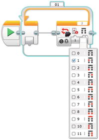
Figure 12-2. Use a LOOP block and Infrared Sensor - Remote trigger to start the bot. The blue highlighting and pull-down menu appear when you click on the tab below the EV3 button symbol. The pull-down shows which Remote button will exit the LOOP.
“But the sensor is facing forward, not toward the rear,” you say. That’s true. But it turns out that the IR Remote has a fairly powerful signal that reflects nicely off of other surfaces, so the beam will end up on the IR Sensor. When you get the bot built, try “shooting” the sensor from different angles, including from behind. You’ll find that reflected IR light works surprisingly well. If your wall does not reflect well enough, you could mount the IR Sensor facing the back. Or, you could change this program and run it backward!
Now you can start on the actual programming blocks needed to perform the actions in the Task List. Look at the Task List on your Design Journal page (turn back to Figure 10-3). The first task is “Move forward to the center of room and stop.” If you’ll think back to Chapter 10, we determined that to get halfway across the room, we needed to program our motors to spin for 13 rotations. Each rotation moves the bot approximately 5.5 inches, so when the motors spin for 13 rotations, the bot will move forward approximately 71 inches, or almost six feet. That’ll be good enough to get the bot near the center of the room.
Place a Move Steering block and configure it with a Duration of 13 rotations for motors B and C. Be aware that I’ve selected the direction for motors B and C as minus (see Figure 12-3). This is because the motors are reversed on my design—facing the front of the bot. Because of this, forward motion for the bot means having these motors spin in the “reverse” direction. If your bot differs, configure your motor directions based on your own design.
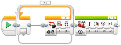
Figure 12-3. Configure the Move Steering block to move the bot forward, halfway into the room
Now it’s time to test. I’m going to save the program (so I don’t lose any of my work or the comments I’ve added) and download it to my bot. When I run the program, the bot should wait until I press the upper-left Infrared Sensor Remote button. After I trigger the sensor, the bot should move forward about six feet and stop. Here goes the test . . . and it worked, exactly as designed. (If your bot did anything differently, check your programming blocks and verify that the number of rotations is correct.)
Next on our Task List is “Turn left to face library.” Back in Chapter 10, I reminded you how to test your bot and obtain the number of degrees to turn for making a right and left turn. When I tested my bot, I obtained a value of -678 degrees when only the right-side wheel was turned (motor B). Drop in your Large Motor block and configure it as shown in Figure 12-4.

Figure 12-4. This Large Motor block will make the bot turn left
Now we test again. When I trigger the Infrared Sensor, the bot moves forward about six feet. It then makes a left turn when motor B turns -678 degrees. So far, so good.
The Task List shows our next step is “Take picture.” Before I configure motor A, however, I do want to add in a WAIT block. I’m worried that motor A might push the button on the camera just as the bot is coming to a stop. This would result in a blurred picture. I’ll configure the WAIT block for two seconds (see Figure 12-5).
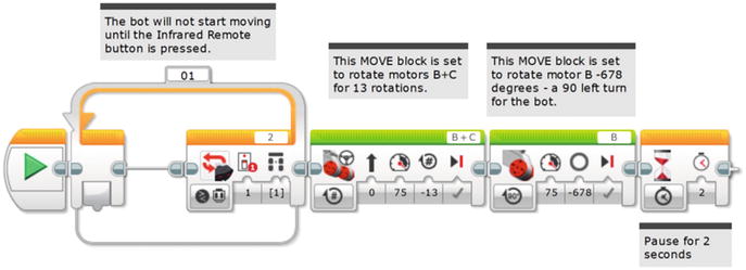
Figure 12-5. A WAIT block allows the bot to stop moving before the picture is taken
Next we need to configure medium motor A to rotate and press the camera button. Because I don’t know how far to turn it, this is where testing comes in. I dropped in a Medium Motor block and configured the motor A to turn three rotations. Since the Medium Motor Camera Trigger Assembly divides motor rotations by a ratio of 24 to 1, three rotations results in exactly 45 degrees of shutter arm movement. During testing, I found this sometimes missed the button entirely. I reduced it to two rotations/30 degrees and tested again; I got the same result. For my third test, I placed the arm directly on the button of the camera and configured the Medium Motor block for one rotation/15 degrees; this time it worked! The button pressed and a picture was taken (see Figure 12-6). And, adding the reverse Medium Motor block for the shutter resets it, which is useful when you’re doing one test after another.

Figure 12-6. Using the Medium Motor block to make medium motor A take a photograph
Note
Depending on the type of camera you’re using, you’ll probably have to perform a few different tests to determine the best way to press the camera button. When trying different motor settings, such as number of rotations or degrees, it’s usually best to start big. Start with a large number of rotations or degrees—if it works, reduce it a little and try again. Keep reducing until you find the lowest setting that works. Your batteries will last much longer!
Finding the Basket
Okay, at this point, our little bot has made it to the center of the room, turned left, paused, and then taken the picture. Looking at the Task List, I see that my next step is “Move forward until black obsidian ring is detected and stop.” I want my bot to start moving forward until its Light Sensor detects the black obsidian rock surrounding the basket. I also want the bot to move forward slowly so it doesn’t get too close to the basket. When the Light Sensor detects a change in the reflected light, I want the bot to stop.
Back in Chapter 10, I told you how to test your Light Sensor to obtain a reading for a “normal surface” and an “obsidian surface.” When I tested my “normal floor” (a light-colored linoleum floor), the Light Sensor returned a value of 80. When I placed the dark paper (black) under the Light Sensor, I got a value of 10. Your values will probably differ a bit. I’m going to program my Light Sensor to check for a value of 20 or less to be safe. When the Light Sensor is triggered (that is, it has a value of 20 or less), the bot is to stop moving forward because it has detected the “obsidian surface.”
Now, to keep the bot moving forward until the Light Sensor is triggered, you’re going to need to use a LOOP block configured to test the Light Sensor. You can see the settings for the LOOP block in Figure 12-7.

Figure 12-7. Using a LOOP block to test whether the Light Sensor is over the obsidian surface. The pull-down menu shows how we select Color Sensor – Reflected Light Intensity.
To make the bot actually approach the basket, throw in a Motor Steering block. With this Motor Steering block, configure motors B and C with a Duration of Unlimited. The Light Sensor will check to see if it’s over the “obsidian surface.” As soon as it is, the bot will exit the LOOP. Then it will coast another two or three inches. To prevent coasting, place a Motor Steering block configured to STOP. By doing it this way, you can make sure the bot doesn’t rush forward quickly and cross too far over the obsidian ring (see Figure 12-8).

Figure 12-8. Using a LOOP and Motor Steering block with the Light Sensor, followed by a Motor Steering set to OFF
After the Light Sensor is triggered and the bot stops, the bot will need to go around the basket with the twine and prepare for the trip back.
Getting Around the Basket
Now the bot is in front of the basket. What’s next? Look at the Task List: “Turn right, move forward short distance, and stop.”
Our first task will be to get the bot to turn right. Back in Chapter 10, I recorded the value as -640 degrees for a right turn. Remember, the negative sign (–) indicates that motor C is turning in reverse. So you’ll insert a Motor Steering block that’s configured to turn motor C in reverse for -640 degrees (see Figure 12-9).
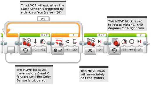
Figure 12-9. A Motor Steering block will allow our bot to make a right turn
We determined in Chapter 10 that the “short distance” was about one foot, and that we would need motors B and C to perform 2.2 rotations. We’ll insert a Motor Steering block (see Figure 12-10) that will get us to point A (turn back to Figure 10-8 for the mini-map).
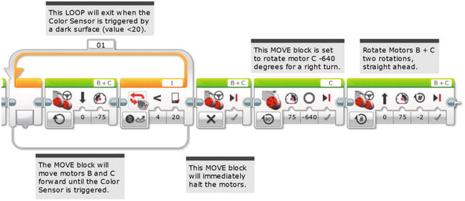
Figure 12-10. Complete the move, with the motors coming to a stop
If you examine the mini-map in Figure 10-8, you’ll notice that once the bot reaches point A, it will make three left turns before heading back to its starting point. It will turn left (1) at point A, move forward, and stop at point B; turn left (2), move forward, and stop at point C; turn left (3), then finally move forward, and stop at point D. This is a perfect location to use a LOOP again. It allows us to reduce the number of programming blocks by performing the same actions three times. Those actions are “Turn Left and Move Forward a Short Distance.” So let’s place the LOOP first (see Figure 12-11).
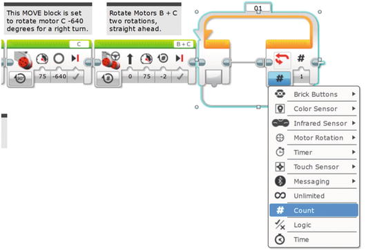
Figure 12-11. The LOOP block will get the bot around the basket. The pull-down menu shows how to select Count.
The LOOP block in Figure 12-11 will run three times. Any blocks placed in it will also run three times before the LOOP block breaks and the program continues. What will happen three times? First, a left turn: a Motor Steering block will turn the bot left. Second, the bot will move forward approximately two or three feet. Back in Chapter 10, we determined that 3.5 rotations would be needed to move our bot two feet. Let’s round that number up to four rotations (28 inches), which should give us plenty of room for our bot to navigate around the basket. So, you’ll first place the Motor Steering block for a left turn (see Figure 12-12).

Figure 12-12. This Motor Steering block turns the bot left
Next, place the Motor Steering block to move the bot forward 28 inches (see Figure 12-13). But take a look at that Large Motor block. It is set for -678 degrees, right? Well, when I ran that program in Figure 12-12, motor B turned… and turned… and turned! It seemed to run forever. I interrupted the robot and looked more closely at the program. It was set for -678 turns! So I changed the Turns symbol to Degrees. That’s what you see in Figure 12-13. I put the next Motor Steering block in, to advance motors B and C four rotations. Again, I downloaded the program, simply running it while holding the SnapShotBot in my hand to test it. All without getting up.
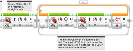
Figure 12-13. This Motor Steering block moves the bot forward a short distance
Now you need to test your bot. At this point, let me describe my test environment and show you how to set up your own.
First, I’m running this test in my living room. I’ve cleared away a chair so I’ll have plenty of room for my bot to run. In Figure 12-14, you can see how I’ve set up my test run. I’ve placed the “basket” (actually a plastic container with a remote control inside for weight) about six feet forward and three feet left from my bot’s starting position. I’ve also placed my piece of dark paper to the right of the basket for the bot’s Light Sensor to detect. If all goes well with my practice run, my bot should end up at point D.
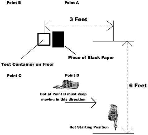
Figure 12-14. Test environment for the SnapShotBot
Because I’ve been testing my bot frequently, I wasn’t surprised that my test run was successful. I knew from previous tests that my bot would enter the library, turn left, take the picture, and move forward until the Light Sensor was triggered. Getting the bot around the basket using a series of three left turns and forward movements worked perfectly. My bot ended up roughly in the area I’ve labeled point D, pointed right and ready to finish its return.
Getting the Bot Home
The hard part is done. All that’s left at this point is getting the bot back to you. There are numerous ways to do this, but the one I’ve selected uses the Infrared Sensor. If you’ll look again at Figure 12-14, my bot is stopped at point D, pointed to the right (back toward the dotted line where the bot first started its motion into the library). What I plan on doing is programming my bot to continue moving forward (moving to the right in Figure 12-14) until I “see” it. What I mean by “see” is that in the real library, the team will be looking through the hole in the wall. When the bot first enters the library and turns left toward the basket, the team will lose sight of the bot. Only when the bot returns and continues to move away from the basket will the team see the bot again. What I plan on doing is simply pressing a Stop button on the Infrared Remote. And as the programmer, I get to decide which button that will be! The Infrared Sensor will detect the IR Remote button press, and I’ll program the bot to stop, turn right, and come back to the hole in the wall. Simple!
First, you add a LOOP that will break when the Infrared Sensor is triggered (see Figure 12-15).
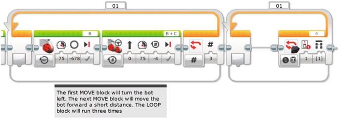
Figure 12-15. Add a LOOP block with the Infrared Sensor configured. This will also use Button 1 of the Infrared Remote.
Next, you add a Motor Steering block that will keep motors B and C moving until the Infrared Sensor is triggered (see Figure 12-16).
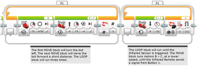
Figure 12-16. The Motor Steering block will run the motors until the LOOP is broken by the Infrared Sensor
Once again, we test. I ran the IR Remote with the same button I used before, and the Infrared Sensor didn’t work! What’s going on? Wrong button? No, it’s the same button we used before. Nuts. Oh, the Infrared Sensor port is set to 4. But the sensor is still wired to port 2, where we used it before. Okay, we need to change port 4 to port 2 in the program.
Test. Again. With the robot in the hand. Now, the Infrared Sensor picked it up fine. Once the bot started rolling, it immediately stopped at my command. Note that it is a lot easier to do these little tests like this with the robot in your hand rather than stepping away from your computer, setting it on the ground, pressing the gray Select button to start the program, hitting the IR Remote, etc. Handling the light floor/dark tape scenario is easily done with white paper and something dark, all held in your hand or on your table.
The next task is “Turn right and move forward to library exit.” That should be easy enough. Drop in a Large Motor block and configure it for a right turn (see Figure 12-17). And let’s double check: yes, it is motor C, and yes, it is set for -640 degrees, just like the one in Figure 12-9. It pays to check and it saves us having to re-test, if we get it right the first time.
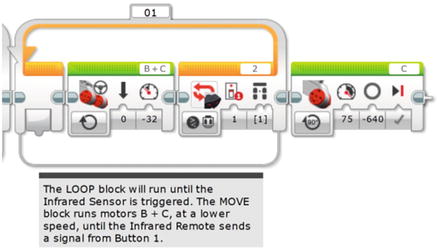
Figure 12-17. This Large Motor block turns the bot right
Use one final LOOP block to run motors B and C continuously. Drop in the LOOP block first (see Figure 12-18). Now, you might think “Why do I need that LOOP block? Can’t I just drop in an Unlimited Large Motor block by itself as my last program instruction?” It turns out that does not work. The motor does have to be in the LOOP block or the last motor command will simply not execute. This can cause a few moments of head scratching since it certainly seems like it ought to work.
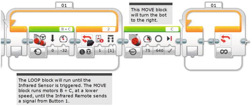
Figure 12-18. This LOOP block will run the motors continuously
Then drop in the final Motor Steering block, configured to run motors B and C for an Unlimited duration (see Figure 12-19). In this case, the slower speed of -32 seemed like a good choice since the bot would be dragging two pieces of twine.

Figure 12-19. This Motor Steering block runs motors B and C
When this is all working, you’ll simply reach in, grab the bot, and turn it off . . . Oh, and be sure to share that smartphone photograph with the team!
That’s it! Download the program and test it. And test it again. Once you’re confident that your SnapShotBot is running perfectly, set up your test environment one more time for the final test. Place the basket, the dark paper, and the bot in their starting positions. If you’re using a regular camera or disposable camera, be sure you’ve wound the camera before sending the bot off. As shown in Figure 12-20, use the Angle Crank on the top of the Worm Gear SubAssembly to position the camera shutter arm up or down, directly above the button.
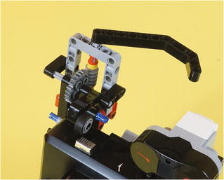
Figure 12-20. This Angle Crank lets you move up or down, to precisely position the camera shutter arm with its small rubber wheel
Get two rolls of string (or twine) and tie one end of each roll to the SnapShotBot. I am using the two tall assemblies on the top of my SnapShotBot to tie my strings. Remember to give plenty of slack on the string. Even better—have someone help you hold one of the rolls so you can both watch the strings and keep the tension off. When you’re ready, press and release the Infrared Sensor and watch your SnapShotBot begin its job. As it rolls in, be sure to feed out plenty of string. You don’t want the string to get tight and pull the bot off course. When the bot turns to take the photograph, feed some more string as it moves toward the basket.
As the bot moves around the basket, you’ll continue to feed it more string. Watch for it to return, and when you see it, press that IR Remote Stop button. The bot should turn (don’t forget to keep feeding more string) and head in your direction. If you’ve given the bot plenty of string, it should come right back to you. Grab the bot and turn it off.
Now, cut the two string ends from your bot and cut the string from the two rolls. Take all four string ends and place them together in your hand. Start pulling very slowly. Keep pulling slowly until you feel some resistance. When you feel the string tighten a little, pull even more slowly. At this point, the string should be pulling the basket toward you. Keep pulling until you’ve got the basket (and the key!) in your hands.
Congratulations! You’ve got the key, which means the team can continue exploring King Ixtua’s tomb.