
In this chapter you’re going to learn (drum-roll, please—cue the announcer) . . .
A PLANNING AND DESIGN PROCESS!
Please don’t let the words scare you. Yes, “planning and design process” could sound boring, but I promise that you’ll have fun with this chapter. I know you’re ready to start putting pieces together to build a bot, but if you take some time and go through these P&D chapters, you’ll be building and programming your own robots in less time, with fewer mistakes.
So, let’s get started. That tomb door is still locked, and you’re going to need the ExploroBot to open it.
The ExploroBot
Do you have a picture of the ExploroBot in your mind already? If so, I’ll bet that it doesn’t look exactly like the one pictured here (see Figure 2-1, a-c). (If it does, you are an amazing mind reader. Call me—we can make a fortune on the stock market.)
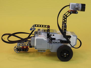

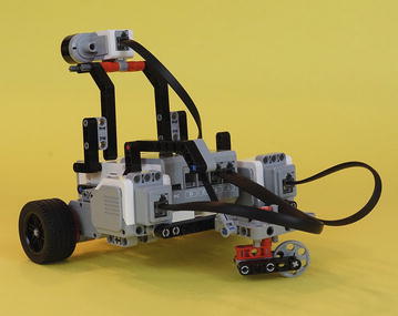
Figure 2-1a-c. The ExploroBot from three different angles
Note
There are five blank Design Journal pages in the back of this book that you can cut out. You’re going to use them to design robots, both from this book and robots of your own design! If you need more pages, you can find a file titled DesignJournal.pdf in the Source Code package available for download on GitHub through the Apress web site ( www.apress.com ).
At the top of the Design Journal page you’ll see the words Robot Name. Go ahead and write ExploroBot in the box and pat yourself on the back. The PLANNING AND DESIGN PROCESS has begun. (You could write something else, such as RobotThatOpensTombDoors, but you might run out of space.)
Are you wondering how that little robot is going to open the tomb door? Good question. And you’re going to answer that question by following along using a page out of Evan’s Design Journal.
The Robot Description
Okay, now that you’ve named your robot, it’s time to describe it. No, I’m not talking about “Short, grey and white, with wheels.” What I mean is, what is this robot supposed to do? At this point, I hope you’ve read Chapter 1. If not, I’ll wait . . . Go back and read it. Okay, have you finished it? Good. Now, what is this robot supposed to do? Don’t say it, write it.
Look on your Design Journal page, and you’ll see Robot Description and a large blank box. Don’t be shy here. This is where you’re going to try your hardest to describe accurately what this robot will do for you. Look back to Figure 1-2 in Chapter 1 if you need a reminder about the path the robot needs to follow. Let me show you what I wrote down, and you can compare it to your description, okay? Here goes (see Figure 2-2).
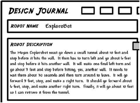
Figure 2-2. Robot description
If your description isn’t exactly like mine, that’s okay. What is important is that you got the major points: Robot moves forward about ten feet, stops, turns. Robot moves six feet, stops, turns. And on and on. Trust me—without an accurate description of the robot, it will be more difficult to build (Chapter 3) and program (Chapter 4). Don’t worry if your description missed something; you’ll get better at this, I promise. You’re going to have more opportunities to write robot descriptions later in the book. By the time you’re finished, you’ll be an expert.
So, what’s next, you ask? Okay, I’ll tell you—you’re going to take the description you wrote and break it down into small, single-item tasks.
The Task List
On your Design Journal page, locate the Task List section. This section is where you’re going to list each individual task that the robot must perform. The good news is that if you wrote down a detailed description (see the previous section), then this section is almost already done.
What do I mean by “individual task?” An individual task is something like “Walk forward five feet” or “Turn doorknob.” Something like “Press the button and turn the wheel” is not an individual task. Your goal is to list the actions your robot will perform, one at a time. Take a look at my task list (see Figure 2-3).
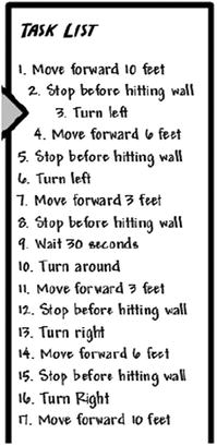
Figure 2-3. The ExploroBot task list
Compare your task list to mine. Were you able to break down the robot description into individual tasks? These individual tasks will help you in many ways, including assembling the correct form for your bot, picking the appropriate sensors to be used, and later when programming the bot.
I’ll give you a small preview of how we’ll use the task list later. Look at Steps 2, 5, 8, 12, and 15—“Stop before hitting wall.” Are you already thinking about how to do this? You’ve got options, of course. There’s the Touch Sensor that can be programmed to stop the robot when it’s triggered. And what about the Infrared Sensor? That sensor sends out a beam of infrared light that’s detected when it bounces back off an object in front of it, such as our wall. It can sense distance from that reflected beam. So you can see that this task list will help you to start thinking about the EV3 components you’ll use. For now, let’s leave the Task List and move on to the next section of the Design Journal.
Limitations and Constraints
You’re going to encounter one obstacle quickly when you begin to design your robots using the LEGO MINDSTORMS EV3 kit. What is it? It’s the number of parts in your kit.
It would be nice if you had access to an unlimited number of sensors, motors, connectors, beams, and other components. But for this book, and the robot designs included in it, I’m assuming that you have the LEGO MINDSTORMS EV3 retail kit. All of the software will work if you have the LEGO MINDSTORMS EV3 education version of the kit, but there are different parts. For example, the education kit uses an Ultrasonic sensor to sense distance. And the education kit comes with a rechargeable battery pack, which is thicker than the flat-bottom battery compartment in the retail kit. That will affect the ExploroBot and PushBot, among others.
When you begin to design your robots, you need to be aware of limitations (or constraints) such as this one. Limitations and/or constraints can come from many different places. Besides the number of parts in your robotics kit, you need to keep in mind issues such as the following:
Robot size and weight (tall, short, heavy, light, wide, thin, square, circular)
Weather and lighting conditions (outdoors, indoors, artificial light, no light)
Floor or surface conditions (soft, hard, wet, slippery, and so on)
Movement requirements (up, down, left, right, forward, backward, diagonal)
There may be some constraints that you won’t encounter until you begin building and testing your robots. Don’t worry if this happens. Your goal at this point should be to write down any limitations that come immediately to mind. Just look back at your Robot Description and Task List and the environment or objects where the robot will interact. Do any constraints come to mind? Write them down on your Design Journal page in the Limitations/Constraints area.
Take a look at Figure 2-4. I’ve written down a couple of sentences that describe what I think are some major constraints for the ExploroBot. Remember, there may be other constraints that won’t show up until we begin testing our design. The important part is to try to identify any obvious constraints before you begin to design and build your bot.

Figure 2-4. The ExploroBot has a few constraints to consider
The constraints for the ExploroBot aren’t too difficult to work around. Let’s take a look at the challenge and see how these constraints will affect the robot design.
First, the robot will enter a tunnel that has a fixed height and width. So the robot you build cannot be too wide or too tall or it simply won’t fit into the tunnel. We know the measurement of the tunnel is 18 inches tall and 18 inches wide. We’ll keep that in mind when we begin to design.
The second constraint is a little trickier. Take a look at Figure 2-5. This is an overhead view of the tunnel and its dimensions. Pay attention to the two corners where the robot will turn.

Figure 2-5. The ExploroBot has to turn a few corners to land on the trigger
The robot must stop before it hits the wall at Corner 1. When it stops, it will turn left and proceed to Corner 2. When it’s turning, we’ll have to be careful to give the robot sufficient space to turn and not bump into the wall. There are numerous methods for building and programming a robot to make a right-angle turn, and I encourage you to experiment with other methods.
So, how can you do this right-angle (or 90-degree) turn and give the robot plenty of room to avoid bumping the walls? Glad you asked.
If you look at Figure 2-6, you’ll notice I’ve zoomed in on the first corner and included some measurements, including the length and width of the ExploroBot. Ideally, we would like the robot to stop a certain distance from the wall and turn left, and the best place for the robot to stop would be directly in the middle of the corner. I don’t want this to get too complicated, so just keep in mind that when the robot turns, it cannot be too close to the wall or, when it turns, it will bump the wall with its front right wheel. So be aware that during the building and programming of the ExploroBot, we’ll be “tinkering” and “tweaking” to get the bot to perform well in a corner.
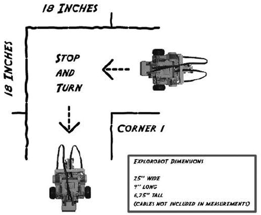
Figure 2-6. The ExploroBot should turn while centered in the corner
Note
During the building and programming of the bot, you’ll perform many tests. During this phase, you’ll test many of the bot’s functions—forward speed, stopping speed, detecting the wall, stopping at a proper distance, and more. I’ll cover this in more detail in Chapters 3 and 4.
The final constraint isn’t so much a constraint as it is a condition that might affect the bot. The surface of the tunnel is stone. It’s a flat rough surface, not made of sand. I’m including this constraint only to demonstrate that you must always be aware of the external conditions the robot will face. Because the surface is flat and rough, we should be able to use the large rubber wheels to move the robot, because they’ll have a good grip on the surface of the tunnel. But this might not always be possible. A wet surface can sometimes cause plastic or thin wheels to simply spin without getting traction, keeping the robot from moving. And what if the robot doesn’t have a surface to roll or walk across? I’ll answer that question in Chapter 6.
Just try to keep an open mind when you’re thinking about the obstacles your robot will face. Examine the robot’s environment, its tasks, and its overall goal as you start to brainstorm about how you’ll solve the problem. And that’s what you’re going to do next. You’re going to brainstorm about this bot’s design, components, and overall appearance in this next Design Journal section—Mindstorm.
Mindstorm
Convenient name for this section, huh? The LEGO MINDSTORMS EV3 robotics kit uses that unique word, Mindstorm. For us, to mindstorm (or brainstorm) is our chance to use our creativity and start developing ideas for how this bot will be designed and built. This is an easy section to complete. What I want you to do is simply write down your questions, observations, and ideas that have been popping into your head since you became aware of the challenge. There are no incorrect items to place in this section except for sketches—those come last. So, to get you started, take a look at Figure 2-7. You’ll see some of my initial thoughts on this challenge, this bot, and the direction I want to take for my initial design.

Figure 2-7. The Mindstorm section contains my initial thoughts
I’m not going to cover all my Mindstorm items here, but I would like to mention a couple and explain how and why I wrote them.
One of my observations was “For the bot to turn, it will require at least 2 motors.” This might seem like common sense, but then again, maybe not. In order for a bot to turn, it has to have a force that makes it turn. Two wheels, connected to a single motor, only give forward and backward motion. For the bot to turn left and right, it requires another motor. By spinning one motor (and its wheel) in one direction and spinning the other motor in the reverse direction, you can cause the bot to turn. This can also be accomplished simply by locking the second motor in place and keeping it from spinning. One wheel will spin, the other wheel will not spin, and the bot will turn.
Another observation was “Sound-control would require Sound sensor and add complexity—should avoid it.” One of my initial ideas was to control the bot by using different sounds and tones. One tone would stop the bot, another tone would make it turn right, and yet another would make it turn left. Then it occurred to me that this would be just too much trouble. My goal is to make the bot as independent as possible and allow it to find its way down the tunnel and back. So the Sound sensor was eliminated.
Your objective here is simply to have some fun and write down some of your initial thoughts on what you’d like to do with your bot design. You might have to take a completely different direction after some testing. You might find you exhaust your supply of a particular component. What you write down isn’t going to lock you in to a particular design. You can change the design anytime, and even start over completely. Print another Design Journal page and try a different design. It’s supposed to be fun, so make it fun. Go crazy with your ideas—the crazier, the better!
Now you’re done with the Robot Description and the Task List is full. You’ve identified some Limitations/Constraints and your Mindstorm items section is overflowing with your thoughts and observations. It’s now time to finish up with the Design Journal’s final section—Sketches.
Sketches
When I draw stick figure people, they tend to have very short legs and very long arms. I still color outside the lines with crayons. I guess what I’m trying to say is that if you’re a professional artist, you don’t have to worry about any competition from me.
I can, however, draw shapes that are fairly close to squares, circles, rectangles, and triangles. And that’s good enough for what I’m going to ask you to do in this section. I want to give you some suggestions before starting on the building of your bot, and I’m going to take my own advice and show you my actual sketches for the ExploroBot.
I’m going to reference some of the ideas I wrote down in the Mindstorm section and show you how I came up with the size and shape of the ExploroBot. First, I’ll start with the shape. Take a look at Figure 2-8 and notice that I started with a basic shape to help determine the placement of sensors, motors, and other parts.
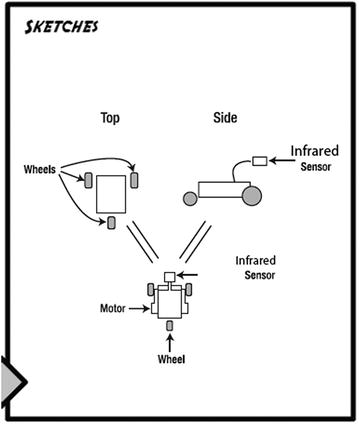
Figure 2-8. In the Sketches section, try to start with placing basic shapes
First, I need to decide between the Touch Sensor and the Infrared Sensor for detecting an approaching wall or obstacle. If I use the Touch Sensor, it will need to be placed far in front of the bot, possibly on a long neck or pole, to allow it time to stop the bot and give it room to turn. But if I use the Infrared Sensor I can place it closer to the bot’s body because it can detect a wall or an obstacle from a distance and it doesn’t require an impact with the wall or obstacle. Because my goal is to keep the ExploroBot as short in length as possible, I’m going to use the Infrared Sensor.
My ExploroBot will require two motors (for turning), the Infrared Sensor, and the Intelligent Brick. And unless I want the Brick to scrape the ground while it moves, I’ll need to give it one or two extra wheels. I think I’ll try to save some weight and keep the size down by using only three wheels.
What I’m envisioning is using the Intelligent Brick as the main body. Two large motors, one on each side of the Brick, will spin the two wheels used for forward and backward motion and for turning. I’ll configure a small third wheel that will pivot to make the bot’s turning a little smoother and give less resistance.
What do your sketches look like? Did you take a different approach to the design of the ExploroBot? Remember, there is no right or wrong solution. If your ExploroBot reaches the end of the tunnel, lands on the pressure plate, and then returns to the tunnel entrance, you’ve succeeded in opening the tomb door.
In Chapter 3, I’m going to walk you through the assembly of my version of the ExploroBot. Feel free to change it up! Move the Infrared Sensor to the back or simply change it to the Touch Sensor. Try giving it four wheels instead of three. Chapter 4 will show you how to program the ExploroBot; at the end of the chapter, I’ll also give you some ideas on how to set up the challenge and test your bot.
Now, let’s build the ExploroBot!